CRoF /'S
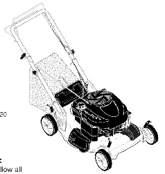
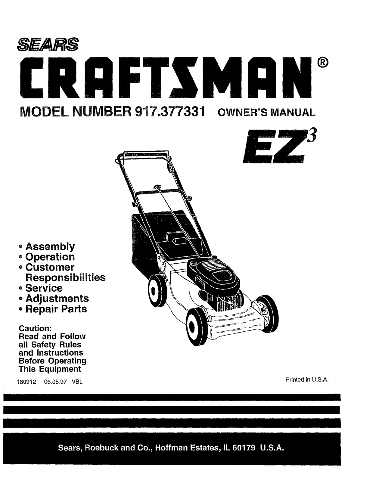
MODEL NUMBER 917.377331 OWNER'S MANUAL
®
, Assembly
o Operation
- Customer
Responsibilities
e Service
o Adjustments
• Repair Parts
Caution:
Read and Follow
all Safety Rules
and Instructions
Before Operating
This Equipment
160912 06.0&97 VBL
IIIIIIIII IIIIIIIIIIIIIII .
Printed in LLS,Ao
SAFETY RULES
Safe Operation Practices for Walk-Behind Mowers
IMPORTANT: THIS CUTTING MACHINE IS CAPABLE OF AMPUTATING HANDS AND FEET AND THROWING OBJECTS.
FAILURE TO OBSERVE THE FOLLOWING SAFETY INSTRUCTIONS COULD RESULT IN SERIOUS INJURY OR DEATH°
SAFETY STANDARDS REQUIRE OPERATOR PRESENCE CONTROLS TO MINIMIZE THE RISK OF INJURY. YOUR UNIT IS
EQUIPPED WITH SUCH CONTROLS. DO NOT ATTEMPT TO DEFEAT THE FUNCTION OF THE OPERATOR PRESENCE
CONTROLS UNDER ANY CIRCUMSTANCES_
TRAINING:
• Read this operator's manual carefully. Become familiar with
the controls and know how to operate your mower propedyo
Learn how to quickly stop mower.
= Do not allow children to use your mower.. Never allow adults
to use mower without proper instructions.
° Keep the area of operation clear of all persons, especially
small children and pets_
° Use mower only as the manufacturer intended and as de-
scribed in this manual
• Do not operate mower if it has been dropped or damaged in
any manner_ Always have damage repaired before using
your mower..
° Do not use accessory attachments that are not recommended
by the manufacturer. Use of such attachments may be
hazardous°
• The blade turns when the engine is running..
PREPARATION:
, Always thoroughly check the area to be mowed and clear it of
all stones, sticks, wires, bones, and other foreign objects°
These objects will be thrown by the blade and can cause
severe injury.
• Always wear safety glasses or eye shields when starting and
while using your mower
, Dress properly, Do not operate mower when barefoot or
wearing open sandals.. Wear only solid shoes with good
traction when mowing°
• Check fuel tank before starting engine. Do not fill gas tank
indoors, when theengine is running or when the engine is hot
Allow the engine to cool for several minutes before filling the
gas tank° Clean off any spilled gasoline before starting the
engine..
• Always make wheel height adjustments before starting your
mower.. Never attempt to do this while the engine is running
= Mow only in daylight or good artificial light..
OPERATION:
° Keep your eyes and mind on your mower and the area being
cut.. Do not let other interests distract you°
* Do not mow wet or slipper.# grass. Never run while operating
your mower. Always be sure of your footing- keep a firm hold
on the handles and walk..
* Do not put hands or feet near or under rotating parts Keep
clear of the discharge opening at all times
, Always stop the engine whenever you leave or are notusing
your mower, or before crossingdriveways, walks, roads, and
any gravel-covered areas_
• Never direct discharge of material toward bystanders nor
allow anyone near the mower white you are operating it.
° Before cleaning, inspecting, or repairing your mower, stop the
engine and make absolutely sure the blade and all moving
parts have stopped.. Then disconnect the spark plug wire and
keep it away from the spark plug to prevent accidental
starting..
- Do not continue to run your mower' if you hit a foreign object..
Follow the procedure outlined above, then repair any dam-
age before restarting and operating you mower.
° Do not change the governor settings or overspeed the
engine. Engine damage or personal injury may result.
• Do not operate your mower if it vibrates abnormally. Exces-
sive vibration is an indication of damage; stop the engine,
safely check for the cause of vibration and repair as required.
• Do not runthe engine indoors. Exhaust fumes are danger-
ous.
° Never cut grass by pulling the mower towards you. Mow
across the face of slopes, never up and down or you might
lose yourfooting Do not mow excessively steep slopes. Use
caution when operating the mower on uneven terrain orwhen
changing directions - maintain good footing.
° Never' operate your mower without proper guards, plates,
grass catcher or other safety devices in place.
MAINTENANCE AND STORAGE:
• Check the blade and the engine mounting bolts often to be
sure they are tightened properly.,
° Check all bolts, nuts and screws at frequent intervals for
proper tightness to be sure mower is in safe working condi-
tion.
8
O
°
Keep all safety devices in place and working
To reduce fire hazard, keep the engine free of grass, leaves
or excessive grease and oil.
Check grass catcher often for deterioration and wear and
replace worn bags.. Use only replacement bags that are
recommended by and comply with specifications of the
manufacturer of your mower.
Always keep a sharp blade en your mower°
Allow engine to cool before storing in any enclosure.
Never store mower with fuel in the tank inside a building
where fumes may reach an open flame or an ignition source
such as a hot water heater, space heater, clothes dryer, etc.
................. iiii ,11',111' ' I ......... ::7"
Look for this symbol to point out im-
portant safety precautions. It means
I
CAUTION!!! BECOMEALERT!!! YOUR
SAFETY IS INVOLVED,
........................................i
CAUTION: Always disconnect spark
plug wire and place wire where it can-
not contact spark plug in order to pre-
vent accidental starting when setting
up, transporting, adjusting or making
repairs.
III III iiiiii ii IU l'lll IIIII II
iii
A WARNING A
The engine exhaust from this product con-
tains cl_emicals known to the State of Califor-
nia to cause cancer, birth defects, or other
reproductive harm.
i, !i ....................... _i11_,,11111 .... _ .....
2
CONGRATULATIONS on your purchase of a Sears Lawn
Mower, it has been designed, engineered and manufac-
tured to give you the best possible dependability and
performance°
Should you experience any problem you cannot easily
remedy, please contact your nearest Sears Authorized
Service CentedDepartment, We have competent, well-
trained technicians and the proper tools to service or repair
this lawn mower.
Please read and retain this manual.. The instructions will
enable you to assemble and maintain your lawn mower
_roperty. Always observe the "SAFETY RULES"..
MODEL
NUMBER
SERIAL
NUMBER
917.,377331
DATE OF PURCHASE
TH EMODEL AND SERIAL NUMBERS WILL BE FOUND
ON A DECAL ATTACHED TO THE REAR OF THE
LAWN MOWER HOUSING.
YOU SHOULD RECORD BOTH SERIAL NUMBER AND
DATE OF PURCHASE AND KEEP IN A SAFE PLACE
FOR FUTURE REFERENCE..
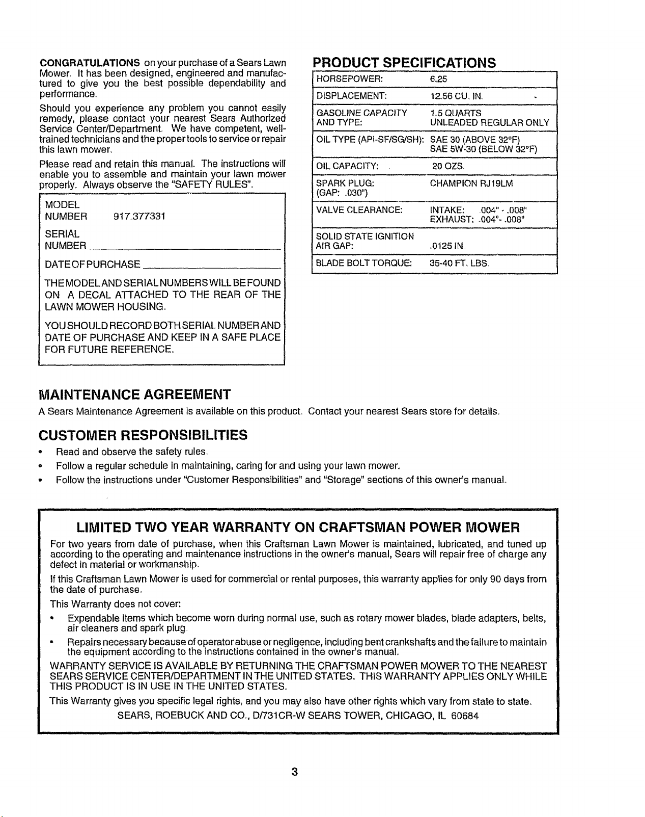
PRODUCT SPECIFICATIONS
HORSEPOWER: 625
DISPLACEMENT: 12,,56CU. IN,
GASOLINECAPACITY 1.5 QUARTS
ANDTYPE: UNLEADEDREGULARONLY
,..,J
OILTYPE (API-SFtSGISH): SAE30 (ABOVE 32°F)
SAE 5W-30 (BELOW 32°F)
OIL CAPACITY: 20 OZS.
SPARK PLUG: CHAMPION RJ19LM
(GAP: 030")
VALVE CLEARANCE: INTAKE: 004" _.008"
EXHAUST: .004"- °008"
SOLIDSTATE IGNITION
AIR GAP: .0125 IN.
BLADE BOLTTORQUE: 35-40 FT. LBS,
MAINTENANCE AGREEMENT
A Sears Maintenance Agreement is available on this product° Contact your nearest Sears store for details.
CUSTOMER RESPONSIBILITIES
, Read and observe the safety rules.
o Follow a regular schedule in maintaining, caring for and using your lawn mower,,
• Follow the instructions under "Customer Responsibilities" and "Storage" sections of this owner's manual
LIMITED TWO YEAR WARRANTY ON CRAFTSMAN POWER MOWER
For two years from date of purchase, when this Craftsman Lawn Mower is maintained, lubricated, and tuned up
according to the operating and maintenance instructions in the owner's manual, Sears will repair free of charge any
defect in material or workmanship.
If this Craftsman Lawn Mower is used for commercial or rental purposes, this warranty applies for only 90 days from
the date of purchase.
This Warranty does not cover:
• Expendable items which become worn during normal use, such as rotary mower blades, blade adapters, belts,
air cleaners and spark plug..
• Repairs necessary because of operator abuse or negligence, including bent crankshafts and the failure to maintain
the equipment according to the instructions contained in the owner's manual.
WARRANTY SERVICE IS AVAILABLE BY RETURNING THE CRAFTSMAN POWER MOWER TO THE NEAREST
SEARS SERVICE CENTER/DEPARTMENT INTHE UNITED STATES. THIS WARRANTY APPLIES ONLY WHILE
THIS PRODUCT IS ti'4USE IN THE UNITED STATES.
This Warranty gives you specific legal rights, and you may also have other rights which vary from state to state.
SEARS, ROEBUCK AND CO., D/731CR-W SEARS TOWER, CHICAGO, IL 60684
3
j i lUllllllln ii illlll _,:.... ' Illlll I
IIIlUU
OF
CONTENTS
SAFETY RULES ............................................................ 2
PRODUCT SPECIFICATIONS ...................................... 3
CUSTOMER RESPONSIBILITIES ...................... 3,12-15
WARRANTY .................................................................. 3
ASSEMBLY ................................................................... 6
OPERATION .................................................................. 8
CUSTOMER RESPONSIBILITIES .............................. 12
SERVICE AND ADJUSTMENTS ................................. 16
STORAGE ................................................................... 18
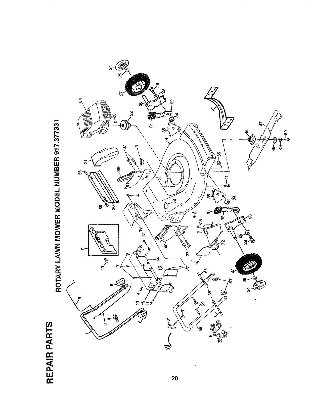
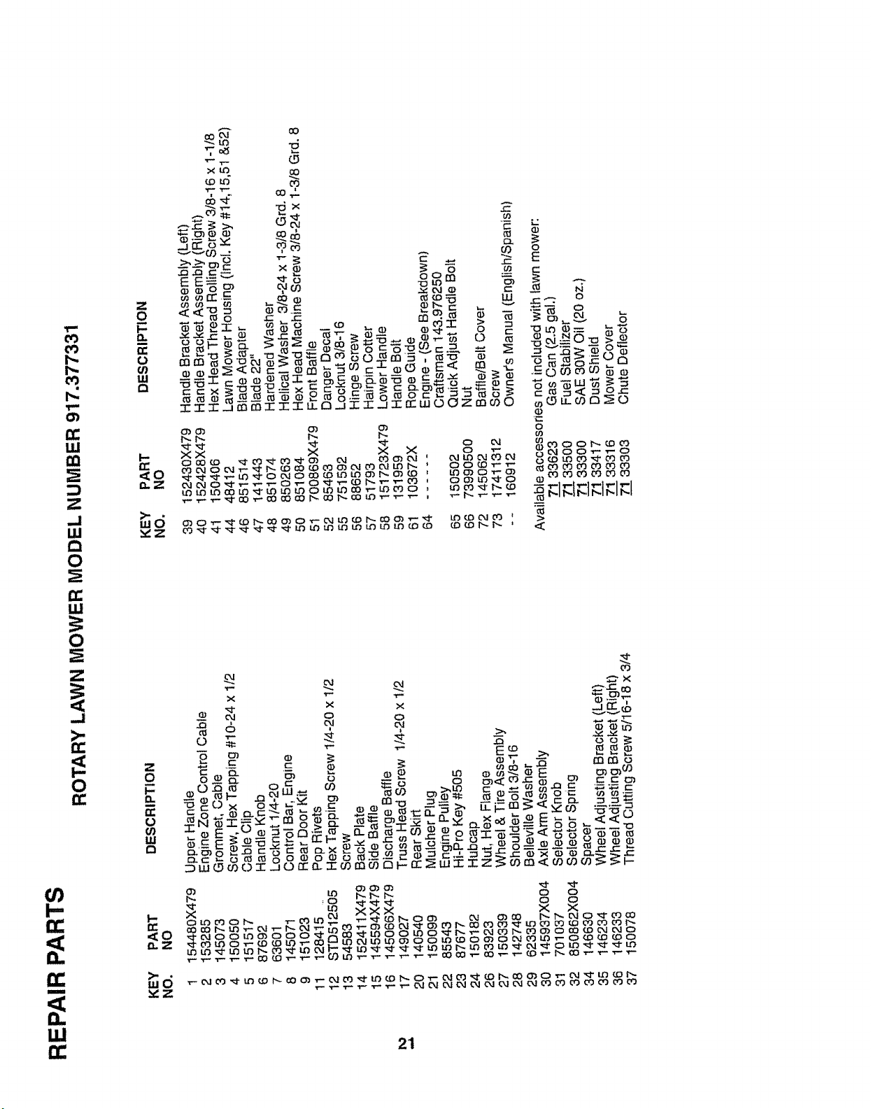
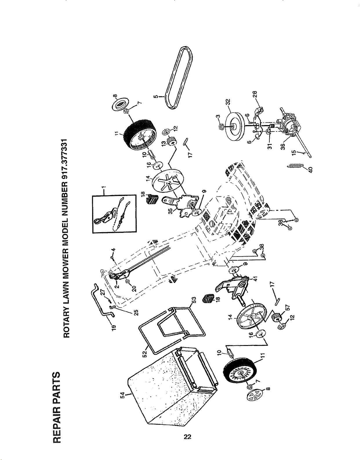
REPAIR PARTS- LAWN MOWER ........................ 19-23
REPAIR PARTS - ENGINE .................................... 24-26
TROUBLESHOOTING ................................................. 27
PARTS ORDERING/SERVICE .................................... 28
iNDEX
A
Adjustments:
Carburetor. ..................................17
Drive Control ............................ 16
Engine Speed .......................... 17
Handle Height ............................17
Height of Cut .....................................9
Air Filter:
Replacement .............................15
Service ...........................................15
Assembly .....................................................6
B
Blade:
Sharpening ...................................13
Replacement ..............................13
C
Controls:
Drive Control ....................................8
Engine Zone Control ...........................8
Engine Speed Control ..................8
Operator Presence Control Bar 8
Customer Responsibilities .... 3,12-15
Air Filter. .............................................15
Blade Care/Replacement ...... !3
Drive Wheels .................................14
Engine ....................................................15
Lubrication.................................15
Spark Ptug .......................................15
Cutting Levels .......................................9
E
Engine:
Air Filter o.......................................15
OilChange ................................15
OilLevel......................................15
OilType .......................................15
Starting .........................................10
Stopping .....................................10
Storage ......................................18
Fuel:
Capacity.....................................3
Storage ........................................t8
Type ...............................................10
H
HandleAdjustment:
Assembly.........................................6
Cutting Height .................................17
L
Lubrication:
Engine..............................................15
Lawn Mower ..................................t2
M
Maintenance Agreement ...................3
Maintenance Schedule ....................12
Mowing Tips.........................................11
OIl:
O
Engine .............................................15
Storage................................................18
Operation:
DriveControl ...............................t0
Engine Control ................................9
Grass Catcher ................................9
Mower ..........................................9
Operator Presence Control Bar 9
R
Repair Parts:
Engine ..................................24-26
Lawn Mower ...................... t 9-23
Responsibilities, Customer... 3,12-.15
S
Safety Rules .................. ............................ 2
Service and Adjustments .............. 16
Carburetor .....................................t7
Drive Belt ...................................16
DriveControl................................17
EngineSpeed ..............................17
Handle ......................................17
Spark Plug......................................................15
Specifications ...............................................3
Speed Control:
Engine ......................................17
Starting the Engine ......................... 10
Stopping the Engine ..........................10
Storage ...........................................18
T
Trouble Shooting Chart ........................27
W
Warranty..........................................................3
4
LAWN
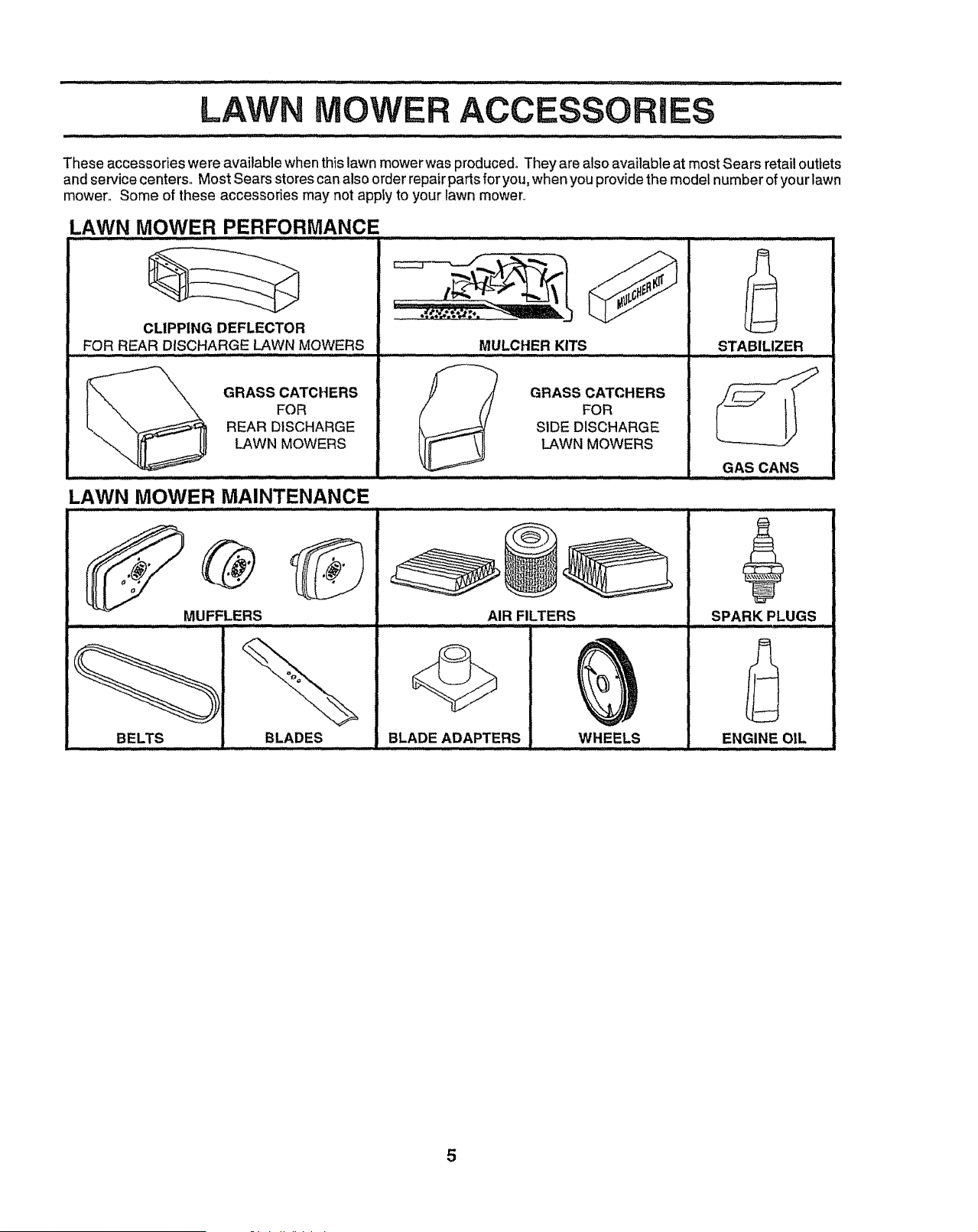
These accessories were available when th!s lawn mowerwas produced° They are also available at most Sears retai! outtets
and service centers. Most Sears stores can also order repair parts for you, when you provide the model number of your lawn
mower° Some of these accessories may not apply to your lawn mower,
LAWN MOWER PERFORMANCE .....
CLIPPING DEFLECTOR
FOR REAR DISCHARGE LAWN MOWERS
GRASS CATCHERS
FOR
REAR DISCHARGE
LAWN MOWERS
LAWN MOWER MAINTENANCE
MUFFLERS
BELTS
MULCHER KITS
GRASS CATCHERS
FOR
SIDE DISCHARGE
LAWN MOWERS
AIR FILTERS
BLADES BLADE ADAPTERS WHEELS
,,,, _.........
STABILIZER
GAS CANS
,_,,,,,,,,_,_ /
SPARK PLUGS
ENGINE OIL
5
MBLY
Read these instructions and this manual in its entirety
before you attempt to assemble or operate your new lawn
mower. Your new lawn mower has been assembled at the
factory with the exception of those parts left unassembled
for shipping purposes. To ensure safe and proper opera_
tion of your' lawn mower', all parts and hardware you
assemble must be tightened securety_ Use the correct
tools as necessary to ensure proper tightness_ All parts
such as nuts, washers, bolts, etc., necessary to complete
the assembly have been placed in the parts bag°
TO REMOVE LAWN MOWER FROM
CARTON
• Remove loose parts included with mower_
° Cut down two end corners of carton and lay end
panel down flat.
• Remove all packing materials except padding be-
tween upper and lower handle and padding holding
operator presence control bar to upper' handle
• Roll lawn mower out of carton and check carton
thoroughly for additional loose parts°
NOW TO SET UP YOUR LAWN
MOWER
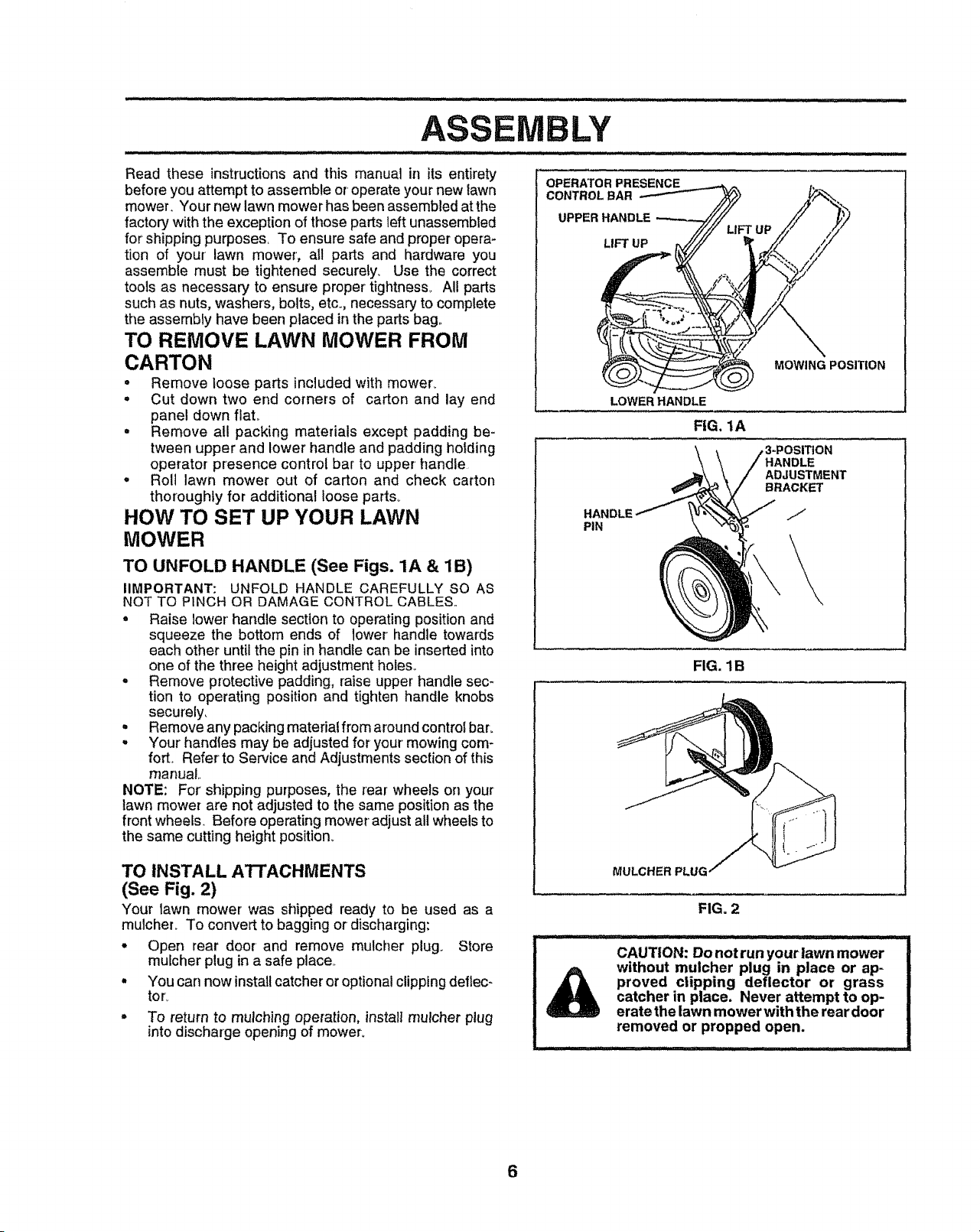
TO UNFOLD HANDLE (See Figs. 1A & 1B)
IIMPORTANT: UNFOLD HANDLE CAREFULLY SO AS
NOT TO PINCH OR DAMAGE CONTROL CABLES.
° Raise lower' handle section to operating position and
squeeze the bottom ends of lower handle towards
each other until the pin in handte can be inserted into
one of the three height adjustment holes..
° Remove protective padding, raise upper handle sec-
tion to operating position and tighten handle knobs
securely_
= Remove any packing material from around control bar.
o Your' handles may be adjusted for your mowing com-
fort. Refer to Service and Adjustments section of this
manual,.
NOTE: For shipping purposes, the rear wheels on your
lawn mower are not adjusted to the same positionas the
front wheels.. Before operating mower adjust all wheels to
the same cutting height position.
OPERATOR PRESENCE
CONTROLBAR
UPPER HANDLE
LIFT UP
MOWING POSITION
LOWER HANDLE
FIG. tA
ON
HANDLE
ADJUSTMENT
BRACKET
HANDLE /
PIN
TO INSTALL A'rrACHMENTS
(See Fig. 2)
Your lawn mower was shipped ready to be used as a
mulcher_ To convert to bagging or discharging:
° Open rear door and remove mulcher plug. Store
mulcher plug in a safe place..
, You can now install catcheror optionalclipping deftec-
tor_
° To return to mulching operation, install rnulcher plug
into discharge opening of mower.
FIG. 1B
MULCHER PLUG
FIG. 2
.... ..... . Jll ......
CAUTION: Do not run your lawn mower
without muicher plug in place or ap-
proved clipping deflector or grass
catcher in place, Never attempt to op-
erate the lawn mower with the rear door
removed or propped open.
6
LY
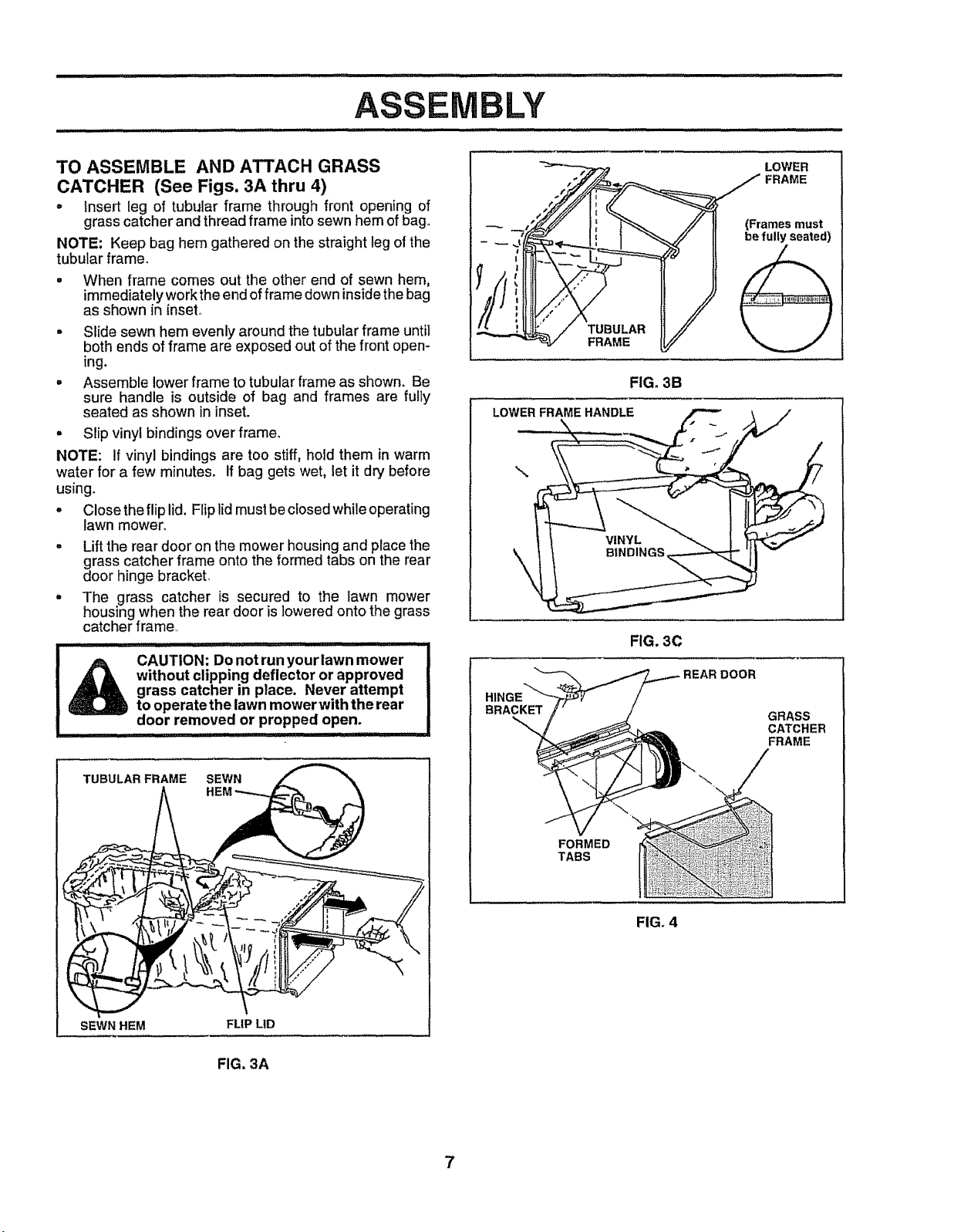
TO ASSEMBLE AND ATTACH GRASS
CATCHER (See Figs. 3A thru 4)
- insert leg of tubular frame through front opening of
grass catcher and thread frame into sewn hem of bag.
NOTE: Keep bag hem gathered on the straight leg of the
tubular frame.
• When frame comes out the other end of sewn hem,
immediately work the end of frame down inside the bag
as shown in inset°
= Slide sewn hem evenly around the tubular frame until
both ends of frame are exposed out of the front open-
ing.
. Assemble lower frame to tubular frame as shown. Be
sure handle is outside of bag and frames are fully
seated as shown in inset.
- Slip vinyl bindings over frame.
NOTE: If vinyl bindings are too stiff, hold them in warm
water for a few minutes. If bag gets wet, let it dry before
using.
• Close the flip lid, Flip lidmust be ctosed while operating
lawn mower°
. Lift the rear door on the mower housing and place the
grass catcher frame onto the formed tabs on the rear
door hinge brackeL
. The grass catcher is secured to the lawn mower
housing when the rear door is lowered onto the grass
catcher frame,
.................. i,i ,i i ilJl iiillll iii
CAUTION: Do not run your lawn mower
m
without clipping deflector or approved
i
grass catcher in place. Never attempt
to operatethe lawn mower with the rear
door removed or propped open.
TUBULAR FRAME SEWN
SEWN HEM
FLIP LID
\
FIG. 3C
DOOR
BRACKET
GRASS
CATCHER
FRAME
FORMED
TABS
FIG. 4
FIG. 3A
7
OPERATION
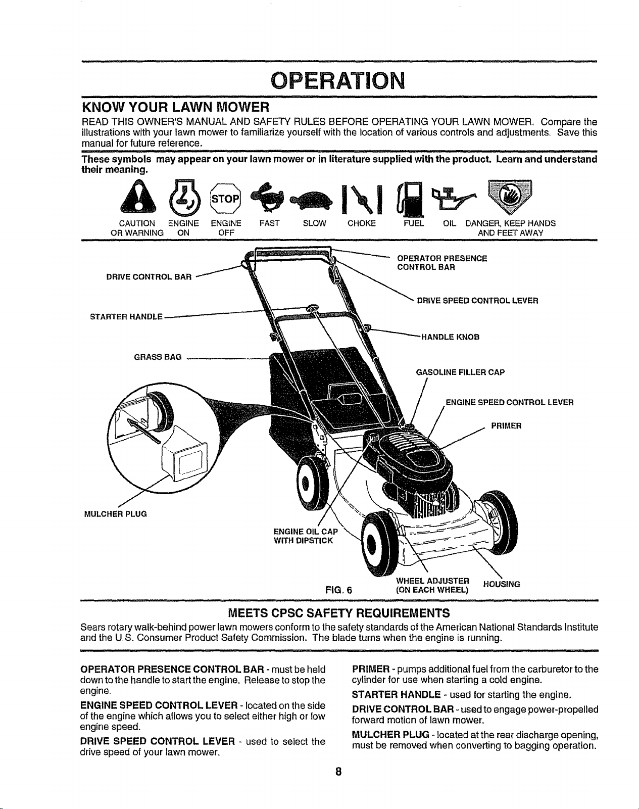
KNOW YOUR LAWN MOWER
READ THIS OWNER'S MANUAL AND SAFETY RULES BEFORE OPERATING YOUR LAWN MOWER, Compare the
illustrations with your lawn mower to familiarize yourself with the location of various controls and adjustments. Save this
manual for' future reference.
..................................... lllll i llll, ........................
These symbols may appear on your lawn mower or in literature supplied with the product. Learn and understand
their meaning.
CAUTION ENGINE ENGINE FAST SLOW CHOKE
OR WARNING ON OFF
,,ll,ii
OPERATORPRESENCE
CONTROLBAR
DRtVECONTROLBAR
DRIVE SPEED CONTROL LEVER
STARTER HANDLI
tANDLE KNOB
GRASS BAG
GASOLINE FILLER CAP
ENGINE SPEED CONTROL LEVER
PRIMER
MULCHER PLUG
ENGINE OIL CAP
WITH DIPSTICK
WHEEL ADJUSTER HOUSING
FIG, 6 (ONEACHWHEEL)
. ill :
MEETS CPSC SAFETY REQUIREMENTS
Sears rotary walk-behind power lawn mowers conformto the safety standards ofthe American National Standards Institute
and the US. Consumer Product Safety Commission° The blade turns when the engine is running_
OPERATOR PRESENCE CONTROL BAR - must be held
down to the handle to start the engine. Release to stop the
engine.
ENGINE SPEED CONTROL LEVER - located onthe side
of the engine which allows you to select either high or low
engine speed.
DRIVE SPEED CONTROL LEVER - used to select the
drive speed of your' lawn mower°
PRIMER - pumps additional fuel from the carburetor to the
cylinder for use when starting a cold engine,
STARTER HANDLE - used for starting the engine.
DRIVE CONTROL BAR - used to engage power-propelled
forward motion of lawn mower.
MULCHER PLUG - located at the rear discharge opening;
must be removed when converting to bagging operation°
8
OPERATION
................. ........... m,i lllll,ll, ,,i i, ii
............ ................... ...... /i ..........................
The operation of any lawn mower can result inforeign objects thrown into the eyes, which can
result in severe eye damage. Always wear safety glasses or eye shietds while operating your
lawn mower or performingany adjustments or repairs. We recommend a wide vision safety
mask over the spectacles or standard safety glasses_
......................................... ....................... :::: i i llll, ,i ii lllll
HOW TO USE YOUR LAWN MOWER E.G " SF'EEO
CO.TROL=-EVER
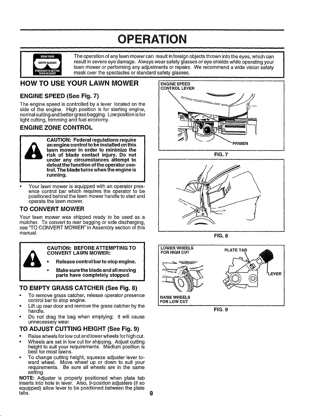
ENGINE SPEED (See Fig, 7)
The engine speed is controlled by a lever located on the
side of the engine,. High position is for starting engine,
normal cutting and better grass bagging° Low position is for
light cutting, trimming and fuel economy.
ENGINE ZONE CONTROL
CAUTIONi Federal regulations require -_
an engine control to be installed on this PRIMER
lawn mower in order to minimize the
risk of blade contact injury, Do not FIG. 7
under any circumstances attempt to
defeat the function of the operator con-
trol, The blade turns when the engine is
running,
...........:: ................... , ................ i,i II I III II IIII
• Your lawn mower is equipped with an operator pres-
ence control bar which requires the operator to be
positioned behind the lawn mower handle to start and
operate the lawn mowen
TO CONVERT MOWER ""
Your lawn mower was shipped ready to be used as a
mulcher. To convert to rear bagging or side discharging,
see "TO CONVERT MOWER" in Assembly section of this
manual° FIG. 8
T . ............2'"_' _, I .. I IIIIIII III IIIIIII II II '1'1'1
CAUTION: BEFORE ATTEMPTING TO LOWERWHEELS PLATETAB
CONVERT LAWN MOWER: FORHIGHCUT- Release control bar to stop engine.
o Make sure the blade and all moving
parts have completely stopped°
TO EMPTY GRASS CATCHER (See Fig. 8)
• To remove grass catcher, release operator presence RAISE WHEELS
control bar to stop engine. FORLOWCUT
= Lift up rear door and remove the grass catcher by the
handle,. FIG. 9
• Do not drag the bag when emptying; it will cause
unnecessary wear.
TO ADJUST CUTTING HEIGHT (See Fig. 9)
• Raise wheels for low cut and lower wheels for high cuL
• Wheels are set in low cut for shipping. Adjust cutting
height to suit your requirements. Medium position is
best for most lawns°
• To change cutting height, squeeze adjuster lever to-
ward wheel. Move wheel up or down to suit your
requirements., Be sure all wheels are in the same
setting.,
NOTE: Adjuster is properly positioned when plate tab
inserts into hole in lever.. Also, 9-position adjusters (if so
equipped) allow lever to be positioned between the plate
tabs_ 9
iI
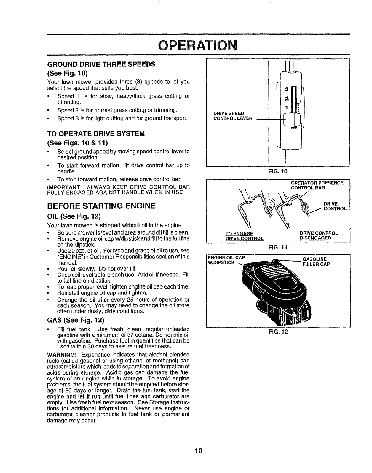
GROUND DRIVE THREE SPEEDS
(See Fig. 10)
Your lawn mower provides three (3) speeds to let you
select the speed that suits you best.
. Speed 1 is for slow, heavy/thick grass cutting or
trimming_
o Speed 2 is for' normal grass cutting or trimming..
= Speed 3 is for lightcutting and for ground transport.
TO OPERATE DRIVE SYSTEM
(See Figs. 10 & 11)
• Select ground speed by moving speed control lever to
desired position.
o To start forward motion, lift drive control bar up to
hand]e_
° To stop forward motion, release drive control bar'.
IMPORTANT: ALWAYS KEEP DRIVE CONTROL BAR
FULLY ENGAGED AGAINST HANDLE WHEN IN USE.
BEFORE STARTING ENGINE
OIL (See Fig. 12)
Your lawn mower is shipped without oil in the engine.
• Be sure mower islevel and area around oil fill is clean_
o Remove engine oil cap w!dipstick and fill to the full line
on the dipstick.
° Use 20 ozs. of oil. Fortypeandgradeofoiltouse, see
"ENGINE" in Customer Responsibilities section of this
manual°
° Pour oil slowly. Do not over fill
o Check oil level before each use_ Add oil if needed. Fill
to full line on dipstick.
° To read proper level, tighten engine oi! cap each time_
° Reinstall engine oil cap and tighten.
• Change the oil after every 25 hours of operation or
each season. You may need to change the oil more
often under dusty, dirty conditions.
GAS (See Fig. 12)
= Fill fuel tank_ Use fresh, clean, regular unleaded
gasoline with a minimum of 87 octane. Do not mix oil
with gasoline. Purchase fuel it! quantities that can be
used within30 days to assure fuel freshness.
WARNING: Experience indicates that alcohol blended
fuels (called gasohol or using ethanol or methanol) can
attract moisture whichleads to separation and formation of
acids during storage,. Acidic gas can damage the fuel
system of an engine while in storage. To avoid engine
problems,the fuel system should be emptied before stor-
age of 30 days or longer, Drain the fuel tank, start the
engine and let it run until fuel lines and carburetor are
empty. Use fresh fuel next season, See Storage Instruc-
tions for additional information. Never use engine or
carburetor cleaner products in fuel tank or permanent
damage may occur.
DRIVE SPEED
CONTROL LEVER
I
I
J
FIG. 10
OPERATOR PRESENCE
\_ \ _ CONTROL BAR
"_" _ _ "_ DRIVE
TO ENGAGE DR]V.E CONT.__OLL
pRIVE CONTROL
FIG. 11
ENGINE OIL CAP GASOLINE
W/DIPSTICK FILLER CAP
FIG. 12
10
TO START ENGINE
• To start a cold engine, push primer five (5) times before
trying to start. Use a firm push,. This step is not usually
necessary when starting an engine which has already
run for a few minutes.
- Move engine speed control lever to high position,.
• Hold operator presence control bar down to the handle
and pull starter handle quickly. Do not aflow starter
rope to snap back.,
- To stop engine, release operatorpresence control barn
NOTE: In cooler weather it may be necessary to repeat
priming steps. In warmerweatheroverpriming maycause
flooding and engine will not start, ifyoudo flood engine wait
a few minutes before attempting to start and do not repeat
priming steps.
MOWING TIPS
• Under certain conditions, such as very tall grass, it may
be necessary to raise the height of cut to reduce
pushingeffort and to keep from overloading the engine
and leaving clumps of grass clippings,.
,, For extremely heavy cutting, reduce the width of cut
and raise the rear of the lawn mower housing one (1)
wheel adjuster setting higher than the front for better
discharge of grass.
- For better grass bagging and most cutting conditions,
the engine speed should be set inthe high position.
• When using a rear discharge lawn mower in moist,
heavy grass, clumps of cut grass may not enter the
grass catcher° Reduce ground speed (pushing speed)
and/or runthe lawn mower over the area a second time.
• tfa trail of grass clippings islefton the right side of a rear
discharge lawn mower, mow in a clockwise direction
with a small overlap to collect the clippings on the next
pass..
• Pores in cloth grass catchers can become _led with dirt
and dust with use and catchers wilt collect less grass..
To prevent this, regularly hose catcher off with water
and let dry before using°
- Keep top of engine around starter clear and clean of
grass clippings and chaff.. This will help engine air flow
and extend engine life..
MAX, I/3
FIG. 13
MULCHING MOWING TIPS
IMPORTANT: FOR BEST PERFORMANCE, KEEP
MOWER HOUSING FREE OF BUILT-UP GRASS AND
TRASH. SEE "CLEANING" IN CUSTOMER
RESPONSIBILITIES SECTION OF THIS MANUAL.
. The special mulching blade will recut the grass clip-
pings many times and reduce them in size so that as
they fatt onto the lawn they will disperse into the grass
and not be noticed.. Also, the mulched grass will
biodegrade quickly to provide nutrients for the lawn.
Always mulch with your highest engine (blade) speed
as this will provide the best recutting action of the
blades.
= Avoid cutting your lawn when it is wet, Wet grass tends
to form clumps and interfereswith the mulching action.
The best time to mow your lawn is the early afternoon.
At this time the grass has dried and the newly cut area
will not be exposed to the direct sun°
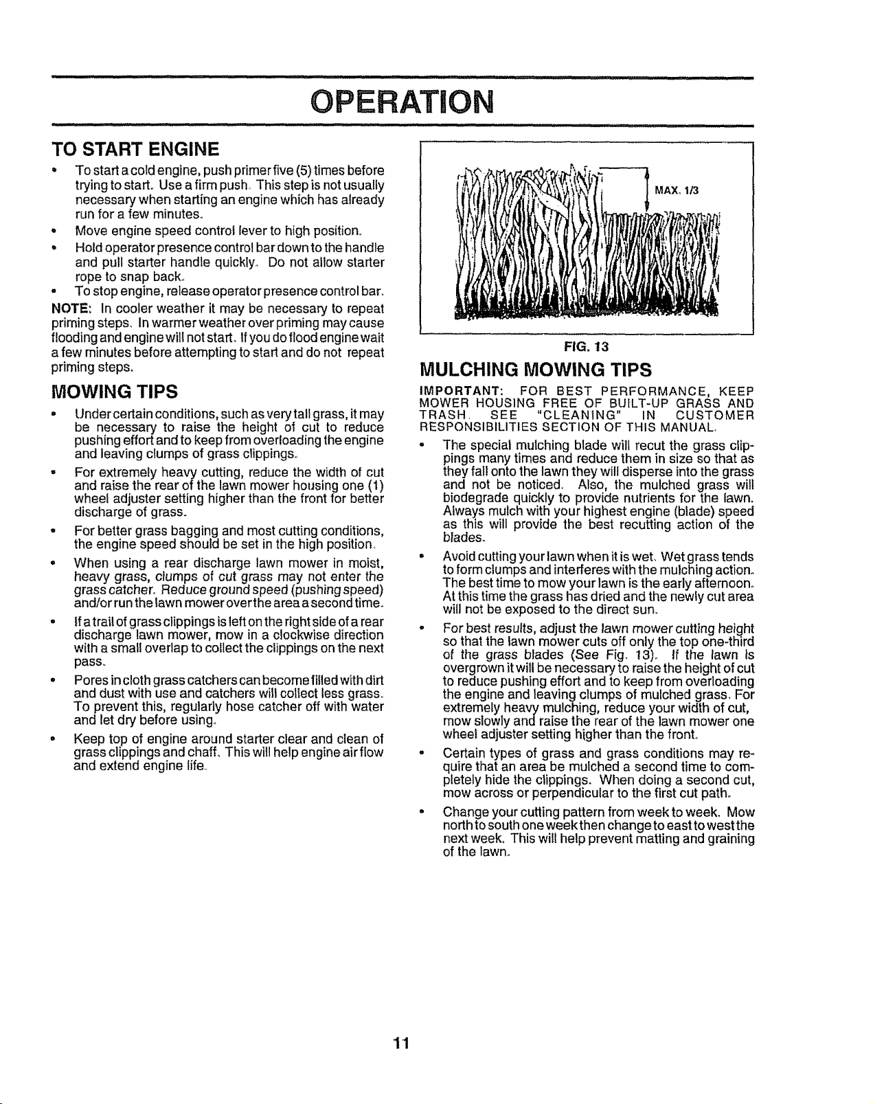
- For best results, adjust the lawn mower cutting height
so that the lawn mower cuts off only the top one-third
of the grass blades (See Fig. 13)o If the lawn is
overgrown itwill be necessary to raise the height of cut
to reduce pushing effort and to keep from overloading
the engine and leaving clumps of mulched grass_ For
extremely heavy mulching, reduce your width of cut,
mow slowly andraise the rear of the lawn mower one
wheel adjuster setting higher than the front°
,, Certain types of grass and grass conditions may re-
quire that an area be mulched a second time to com-
pletely hide the clippings. When doing a second cut,
mow across or perpendicular to the first cut path.
= Change your cutting pattern from week to week. Mow
northto south one week then change to east to west the
next week, This wil! help prevent matting and graining
of the lawn.
11
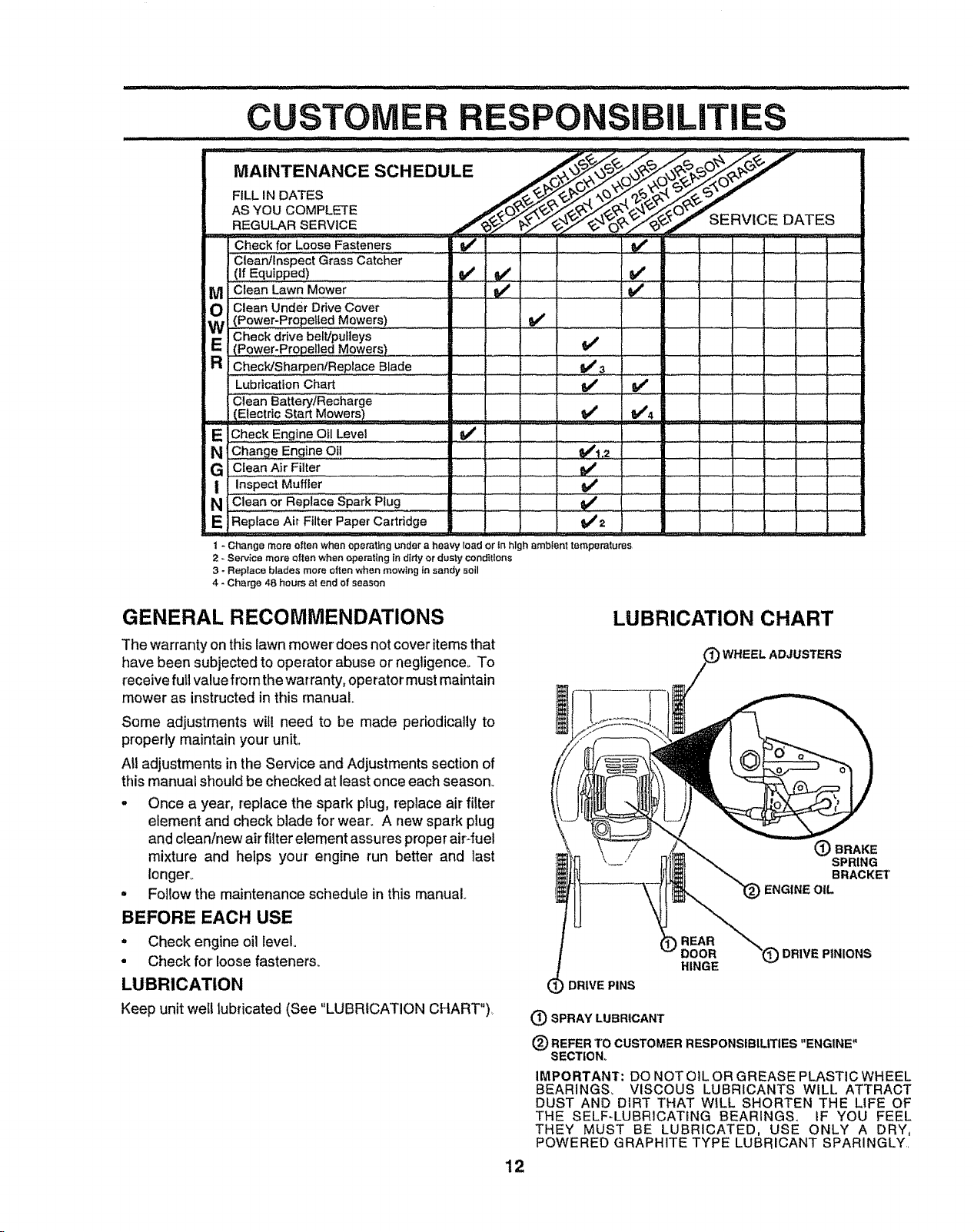
...... ....
AsYOUCOMPL_E ./'_. _',,,_._n_--"--
REGU_RSERVICE.... .___HVl_:_ UA._'_
Check for Loose Fasteners i
Clean/Inspect Grass Catcher
(If Equipped)
M! Clean Lawn Mower
O Clean Under Ddve Cover
(Power-Propelled Mowers) .............. : .................,
E i Check drive belt/pulleys
(Power-Pr0pelled Mowers) i .......
R, Check/Sharpen!Bop,aceB,ade .... tlJ s ,
Lubrication Chart M_' I_
Clean BatterytRecharge
IE!_ot,cSta_Mower,) I," V', .
E[_eckEng!"eOilLeve_ i" .._ ................... !
NI_ 0, " I: V'_I=' '
G / Clean Air Fitter _ _ ,,, _ i_ :
I In.spectMuffler _ '--r , ..... .....
N 1Clean or Replace Spark Plug ........._#'
E iRepiace Air FilterPaper Caitddge ............... _2 ! ............
v' J
v' u"
u,'
i - Change more often when operating under a heavy lead or tn high ambient temperatures
2 - Service more often when operating In ditty or dusty cond{tlons
3 - Replace blades more often when mowing in sandy soil
4 - Charge 48 hours at end of season
GENERAL RECOMMENDATIONS
The warranty on this lawn mower does not cover items that
have been subjected to operator abuse or negligenceo To
receivefull value from the warranty, operator must maintain
mower as instructed in this manual.
Some adjustments will need to be made periodically to
properly maintain your unit.,
All adjustments in the Service and Adjustments section of
this manual should be checked at least once each season_
. Once a year, replace the spark plug, replace air filter
element and check blade for wear. A new spark plug
and clean/new air filter element assures proper air-fuel
mixture and helps your engine run better and last
Ionger_
• Follow the maintenance schedule in this manual
BEFORE EACH USE
• Check engine oil level
• Check for loose fasteners.
LUBRICATION
Keep unit well lubricated (See "LUBRICATION CHART")_
LUBRICATION CHART
WHEEL ADJUSTERS
(_ BRAKE
SPRING
BRACKET
ENGtNE OIL
DRIVE PINS
REAR
DOOR (_ DRIVE PINIONS
HINGE
(_)SPRAYLUBRICANT
(_) REFER TO CUSTOMER RESPONSIBILITIES "ENGINE"
SECTtON_
IMPORTANT: DO NOT OtL OR GREASE PLASTIC WHEEL
BEARINGS_ VISCOUS LUBRICANTS WILL ATTRACT
DUST ANO DIRT THAT WtLL SHORTEN THE LIFE OF
THE SELF-LUBRICATING BEARINGS, iF YOU FEEL
THEY MUST BE LUBRICATED, USE ONLY A DRY,
POWERED GRAPHITE TYPE LUBRICANT SPARINGLY,
12
LAWN MOWER
Always observe safety rules when performing any mainte-
nance._
TIRES
. Keep tires free of gasoline, oil, or insect control chemi-
cals which can harm rubber,
• Avoid stumps, stones, deep ruts, sharp objects and
other hazards that may cause tire damage°
BLADE CARE
Forbest results, mowerblade must be kept sharpo Replace
bent or damaged blades.
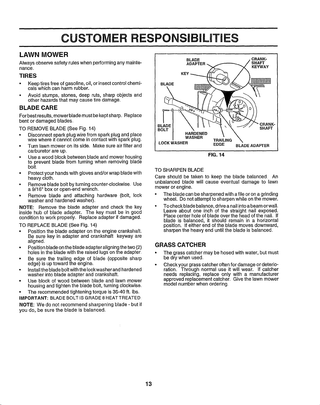
TO REMOVE BLADE (See Fig° 14)
• Disconnect spark plug wire from spark plug and place
wire where it cannot come in contact with spark plugo
. Turn lawn mower on its side, Make sure air filter and
carburetor are upo
o Use a wood block between blade and mower housing
to prevent blade from turning when removing blade
bolt.
• Protect your hands with gloves and/or wrap blade with
heavy cloth.
° Remove blade bolt by turning counter-clockwise, Use
a 9/16 box or open-end wrench_
° Remove blade and attaching hardware (bolt, lock
washer and hardened washer),.
NOTE: Remove the blade adapter and check the key
inside hub of blade adapter, The key must be in good
condition to work properly. Replace adapter if damaged.
TO REPLACE BLADE (See Fig,. 14)
° Position the blade adapter on the engine crankshaft.
Be sure key in adapter and crankshaft keyway are
aligned.,
- Position blade on the blade adapter aligning the two (2)
holes in the blade with the raised lugs on the adapter_
° Be sure the trailing edge of blade (opposite sharp
edge) is up toward the engine.
= instalf the blade boit with the lock washer and hardened
washer into blade adapter and crankshaft.
= Use block of wood between blade and lawn mower
housing and tighten the blade bolt, turning clockwise..
• The recommended tightening torque is 35-40 ft, Ibs_
IMPORTANT: BLADE BOLT IS GRADE 8 HEATTREATED.
NOTE: We do not recommend sharpening blade - but if
you do, be sure the blade is balanced.
iLITI S
BLADE
BLADE
ADAPTER
,CRANK-
SHAFT
KEYWAY
HARDENED
WASHER
TRA1LING
LOCK WASHER EDGE
CRAN_
SHAFT
BLADE ADAPTER
FIG. 14
TO SHARPEN BLADE
Care should be taken to keep the blade balanced. An
unbalanced blade witl cause eventual damage to lawn
mower or engine.
o The blade can be sharpened with a file or on a grinding
wheel° Do not attempt to sharpen while on the mower.
° To check blade balance, drive a nail into a beam orwaIL
Leave about one inch of the straight nail exposed.
Place center hole of blade over the head of the nail. If
blade is balanced, it should remain in a horizontal
position° If either end of the blade moves downward,
sharpen the heavy end until the blade is balanced_
GRASS CATCHER
°
o
The grass catcher may be hosed with water, but must
be dry when used,
Check your grass catcher often for damage or deterio-
ration., Through normal use it will wear. If catcher
needs replacing, replace only with a manufacturer
approved replacement catcher,. Give the lawn mower
model number when ordering,
13
CUSTOM
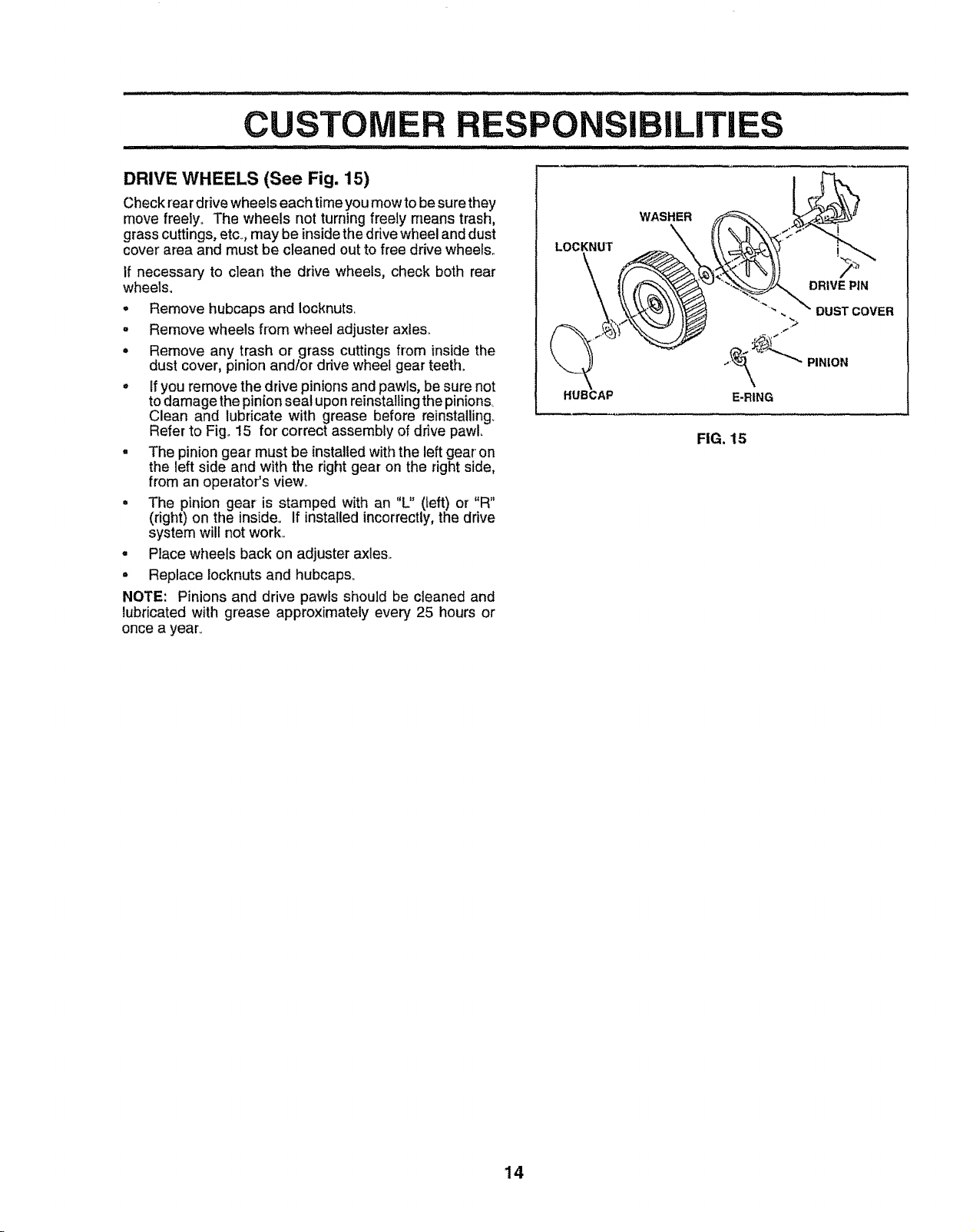
DRIVE WHEELS (See Fig. 15)
Check rear drive wheelseach time you mow to besure they
move freely. The wheels not turning freely means trash,
grass cuttings, etc. may be inside the drive wheel and dust
cover' area and must be cleaned out to free drive wheels,,
If necessary to clean the drive wheels, check both rear
wheels.
• Remove hubcaps and Iocknuts,
= Remove wheels from wheel adjuster axles.
• Remove any trash or grass cuttings from inside the
dust cover, pinion and/or drive wheel gear teeth.
° If you remove the drive pinions and pawls, be sure not
to damage the pinion seal upon reinstalling the pinions_
Clean and lubricate with grease before reinstalling_
Refer to Fig,, 15 for correct assembly of drive pawL
. The pinion gear must be installed with the left gear on
the left side and with the right gear on the right side,
from an operator's view.
• The pinion gear is stamped with an "L" (left) or "R"
(right) on the inside,, If installed incorrectly, the drive
system will not work,,
° Place wheels back on adjuster axles.
• Replace locknuts and hubcaps.
NOTE: Pinions and drive pawls should be cleaned and
lubricated with grease approximately every 25 hours or
once a year.
LOCKNUT
HUBCAP
WASHER
DRIVE PIN
FIG. 15
14
CUSTOMER RESPONSiBiLiTiES
ENGINE
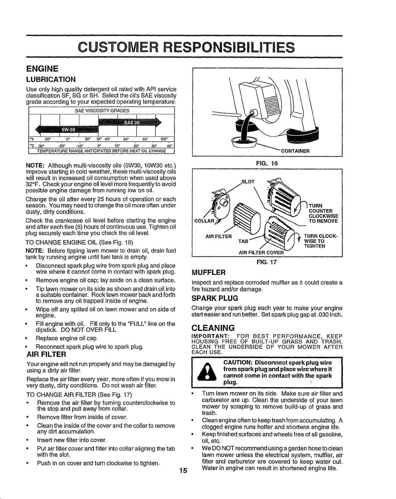
LUBRICATION
Use only high quality detergent oil rated with API service
classification SF, SG or SH,, Select the oil's SAE viscosity
grade according to your expected operating temperature,
SAE VISCOSITY GRADES
°F -20 ° 0 ° 30" 32 _ 40 _ 60" BOA 100'
°__c_0o .ao. -IOO ;" 1o' _oo _o 4oo
i TEMPERATURE RANGE A_'-_ICIPATED BEFORE NEXT OiL CHANGE 3ONTAINER
FIG. 16
NOTE: Although multi-viscosity oils (5W30, 10W30 etc,,)
improve starting in cold weather, these multi-viscosity oils
will result in increased oil consumption when used above
32°F. Check your engine oil level more frequently to avoid
possible engine damage from running low on oil
Change the oil after every 25 hours of operation or each
season. You may need to change the oil more often under
dusty, dirty conditions,,
Check the crankcase oi! level before starting the engine
and after each five (5) hours of continuous use. Tighten oil
plug securely each time you check the oil level.
TO CHANGE ENGINE OIL (See Fig,, 16)
NOTE: Before tipping lawn mower to drain oil, drain fuel
tank by running engine until fuel tank is empty,
. Disconnect spark plug wire from spark plug and piace
wire where it cannot come in contact with spark plug.
- Remove engine oil cap; lay aside on a clean surface.
= Tip lawn mower on its side as shown and drain oil into
a suitable container,, Rock lawn mower back and forth
to remove any oil trapped inside of engine.
• Wipe off any spilled oil on lawn mower and on side of
engine.
- Fill engine with oil. Fill only to the "FULL" line on the
dipstick,, DO NOT OVER FILL,
= Replace engine oil cap.
o Reconnect spark plug wire to spark plugo
AIR FILTER
Your engine will not run properly and may be damaged by
using a dirty air filter,
Replace the air filter every year, more often if you mow in
very dusty, dirty conditions,, Do not wash air filter.
TO CHANGE AIR FILTER (See Fig. 17)
° Remove the air filter by turning counterclockwise to
the stop and pull away from collar°
• Remove filter from inside of cover.,
• Clean the inside of the cover and the collar to remove
any dirt accumulatlono
• Insert new filter into cover,,
• Put air filter cover and filter into collar aligning the tab
with the slot.
- Push in on cover and turn clockwise to tighten.
TURN
COUNTER
CLOCKWISE
TO REMOVE
15
AIR FILTER
TURN CLOCK-
WISE TO
TIGHTEN
MUFFLER
AIR FILTER COVEF
FIG, 17
Inspect and replace corroded muffler as it could create a
fire hazard and/or damage,
SPARK PLUG
Change your spark plug each year to make your engine
start easier and run better_ Set spark plug gap at .030 inch.
CLEANING
IMPORTANT: FOR BEST PERFORMANCE, KEEP
HOUSING FREE OF BUILT-UP GRASS AND TRASH.
CLEAN THE UNDERSIDE OF YOUR MOWER AFTER
EACH USE,,
IA.................................................!
CAUTION: Disconnect spark plug Wire
from spark plug and place wire where it
cannot come in contact with the spark
plug.
. Turn lawn mower on its side° Make sure air filter and
carburetor are up,, Clean the underside of your lawn
mower by scraping to remove build-up of grass and
trash.
° Clean engine oftento keep trash from accumulating, A
clogged engine runs hotter and shortens engine Life°
• Keep finished surfaces and wheels free of all gasoline,
oil, etco
- We DO NOT recommend using a garden hose to clean
lawn mower unless the electrical system, muffler, air
filter and carburetor are covered to keep water out.
Water in engine can result in shortened engine lifeo
RVICE AND ADJUSTMENTS
......CAUTioN: BEFORE PERFORMING ANY SERVICE OR ADJUSTMENTS:
Release control bar and stop engine.
Make sure the blade and all moving parts have completely stopped.
Disconnect spark plug wire from spark plug and place where it cannot come in contact with plug,
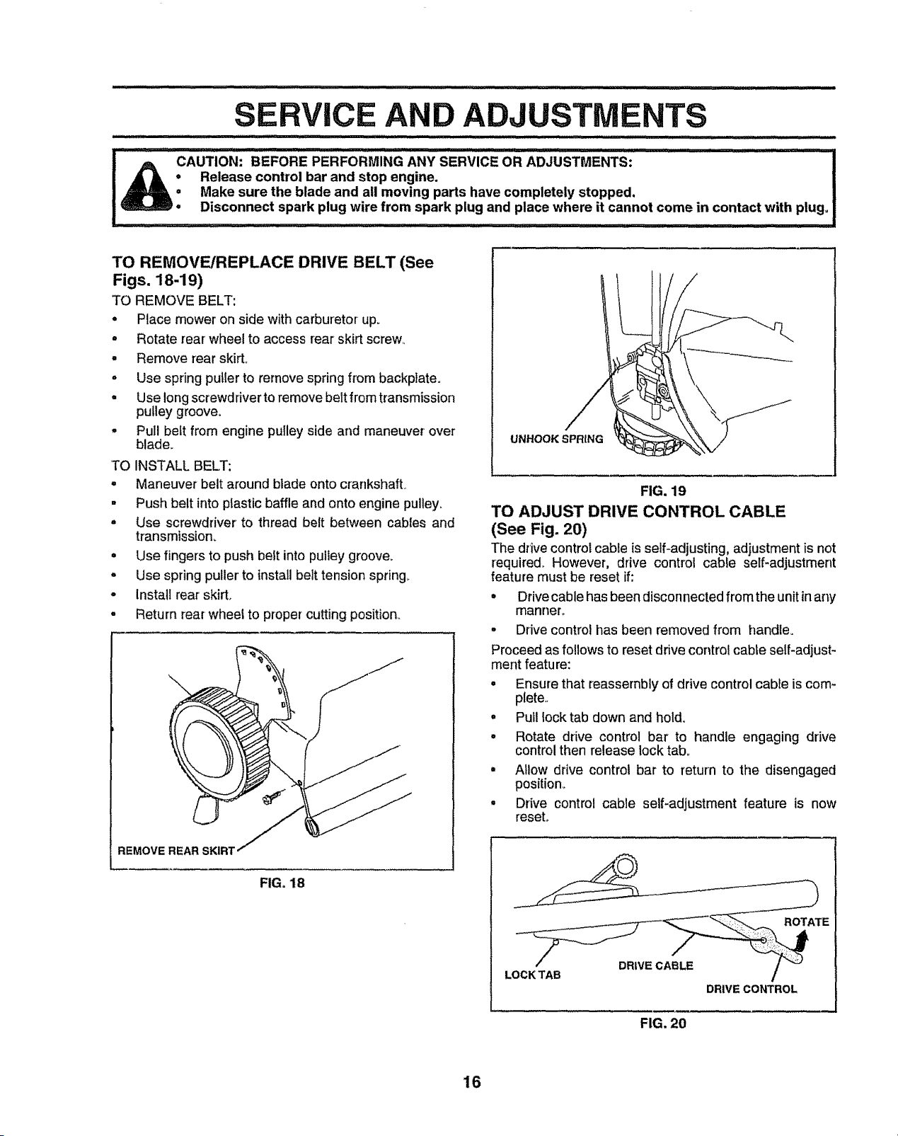
TO REMOVE/REPLACE DRIVE BELT (See
Figs. 18-19)
TO REMOVE BELT:
. Place mower on side with carburetor up_
• Rotate rear wheel to access rear skirt screw..
, Remove rear skirt..
, Use spring puller to remove spring from backpIate.
° Use long screwd river to remove belt from transmission
pulley groove.
, Pull belt from engine pulley side and maneuver over
blade.
TO INSTALL BELT:
° Maneuver belt around blade onto crankshaft_
= Push belt into plastic baffle and onto engine pulley.
° Use screwdriver to thread belt between cables and
transmission_
o Use fingers to push belt into pulley groove.
o Use spring puller' to install belt tension spring._
o Install rear skirt.
. Return rear wheel to proper cutting position..
REMOVE REAR SKIRT
FIG. 18
UNHOOK SPRING
FIG. 19
TO ADJUST DRIVE CONTROL CABLE
(See Fig. 20)
The drive control cable is self-adjusting, adjustment is not
required_ However, drive control cable self-adjustment
feature must be reset if:
• Drivecable has been disconnected from the unitin any
manner°
° Drive control has been removed from handle.
Proceed as follows to reset drive control cable self-adjust-
ment feature:
, Ensure that reassernbly of drive controlcable is com-
plete._
° Pull lock tab down and hold.
° Rotate drive control bar to handle engaging drive
control then release lock tab.
° Allow drive control bar to return to the disengaged
position_
, Drive control cable self-adjustment feature is now
reset.
ROTATE
LOCK TAB
DRIVE CABLE
DRIVE CONTROL
FIG. 20
16
iii........................................... , ..............................................................
SERVlC ANDA USTMENTS
REAR DEFLECTOR
The rear deflector, attached between the rear wheels of
your lawn mower, is provided to minimize the possibility
that objects wilt be thrown outof the rear of the lawn mower
into the operator's mowing position., If the rear deflector
becomes damaged, it should be replaced.
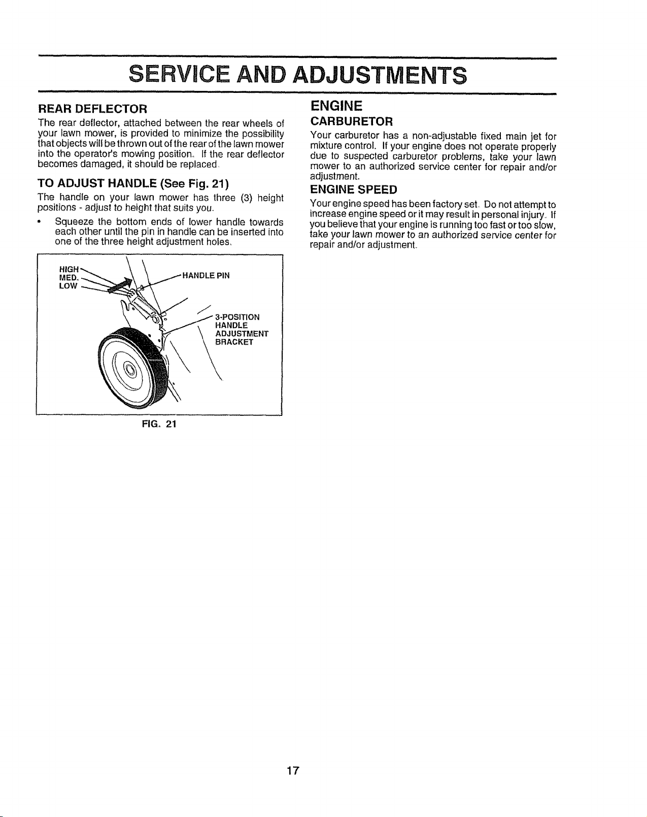
TO ADJUST HANDLE (See Fig. 21)
The handle on your lawn mower has three (3) height
positions - adjust to height that suits you.
• Squeeze the bottom ends of lower handle towards
each other until the pin in handle can be inserted into
one of the three height adjustment holes.
ENGINE
CARBURETOR
Your carburetor has a non-adjustable fixed main jet for
mixture control, if your engine does not operate properly
due to suspected carburetor problems, take your lawn
mower to an authorized service center for repair and/or
adjustment.
ENGINE SPEED
Your engine speed has been factory set Do not attempt to
increase engine speed or it may result inpersonal injury if
you believe that your engine is running too fast or too slow,
take your Fawnmower to an authorized service center for
repair and/or adjustment,
MEDo
LOW
ISITION
HANDLE
ADJUSTMENT
BRACKET
\
FIGo 21
17
STO
Immediately prepare your lawn mower for storage at the
end of the season or if the unit will not be used for 30 days
or more°
LAWN MOWER
When lawn mower is to be stored for a periodof time,clean
it thoroughly, remove all dirt, grease, leaves, etc., Store in
a clean, dry area.
• Clean entire lawn mower (See "CLEANING" in the
Customer Responsibilities section of this manual)_
• Lubricate as shown in the Customer Responsibilities
section of this manual.
- Be sure that all nuts, bolts, screws, and pins are
securely fastened, Inspect moving partsfor damage,
breakage and wear. Replace if necessary_
o Touch up all rusted or chipped paint surfaces; sand
lightly before painting.
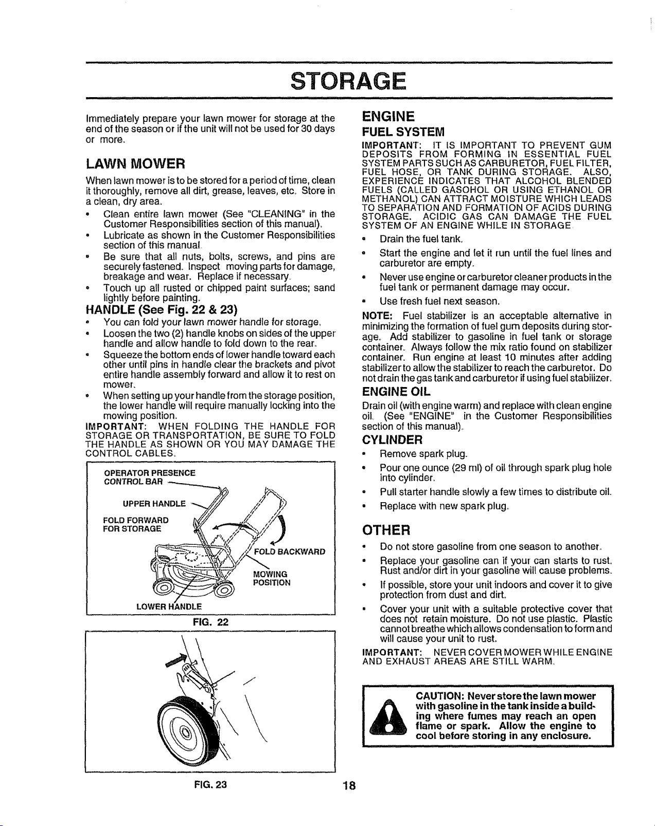
HANDLE (See Fig. 22 & 23)
o You can fold your lawn mower handle for storage°
• Loosen the two (2) handle knobs on sides of the upper
handle and allow handle to fold down to the rear,,
° Squeeze the bottom ends of lower handle toward each
other until pins in handle clear the brackets and pivot
entire handle assembly forward and allow it to rest on
mower.
• When setting up your handle fromthe storage position,
the lower handle will require manually locking into the
mowing position.
IMPORTANT: WHEN FOLDING THE HANDLE FOR
STORAGE OR TRANSPORTATION, BE SURE TO FOLD
THE HANDLE AS SHOWN OR YOU MAY DAMAGE THE
CONTROL CABLES_
OPERATOR PRESENCE
CONTROL BAR
UPPER HANDLE
FOLD FORWARD
FOR STORAGE
FOLD BACKWARD
MOWING
POSITION
FIG, 22
\
j_
ENGINE
FUEL SYSTEM
IMPORTANT: IT IS IMPORTANT TO PREVENT GUM
DEPOSITS FROM FORMING IN ESSENTIAL FUEL
SYSTEM PARTS SUCH AS CARBURETOR, FUEL FILTER,
FUEL HOSE, OR TANK DURING STORAGE. ALSO,
EXPERIENCE INDICATES THAT ALCOHOL BLENDED
FUELS (CALLED GASOHOL OR USING ETHANOL OR
METHANOL) CAN ATTRACT MOISTURE WHICH LEADS
TO SEPARATION AND FORMATION OF ACIDS DURING
STORAGE. ACIDIC GAS CAN DAMAGE THE FUEL
SYSTEM OF AN ENGINE WHILE IN STORAGE
• Drain the fuel tank_
° Start the engine and tet it run until the fuel lines and
carburetor are empty.
= Never use engine or carburetor cleaner products in the
fuel tank or permanent damage may occur.
- Use fresh fuel next season,
NOTE: Fuel stabilizer is an acceptable alternative in
minimizing the formation of fuel gum deposits during stor-
age° Add stabilizer to gasoline in fuel tank or storage
container_ Always follow the mix ratio found on stabilizer'
container. Run engine at least 10 minutes after adding
stabilizerto alLowthe stabilizer to reachthe carburetor. Do
not drain the gas tank and carburetor ifusing fuel stabilizer.
ENGINE OIL
Drain oil (with engine warm) and replace with clean engine
oil._ (See "ENGINE" in the Customer Responsibilities
section of this manual),
CYLINDER
* Remove spark plug.
° Pour one ounce (29 ml) of oil through spark plug hole
into cylinder.
= Pull starter handle slowly a few times to distribute oil.
° Replace with new spark plug.,
OTHER
• Do not store gasoline from one season to another.
• Replace your gasoline can if your can starts to rust.
Rust andtor dirt in your' gasoline will cause problems.,
° If possible, store your unit indoors and cover it to give
protection from dust and dirt.
° Cover your unit with a suitable protective cover that
does not retain moisture. Do not use plastic. Plastic
cannot breathe which allows condensation to form and
will cause your unit to rust,
IMPORTANT: NEVER COVER MOWER WHILE ENGINE
AND EXHAUST AREAS ARE STILL WARM.
CAUTION: Never storethe Dawnmower
with gasoline in the tank inside a build-
ing where fumes may reach an open
flame or spark. Allow the engine to
cool before storing in any enclosure.
: ..................... ULI
FIG. 23 18
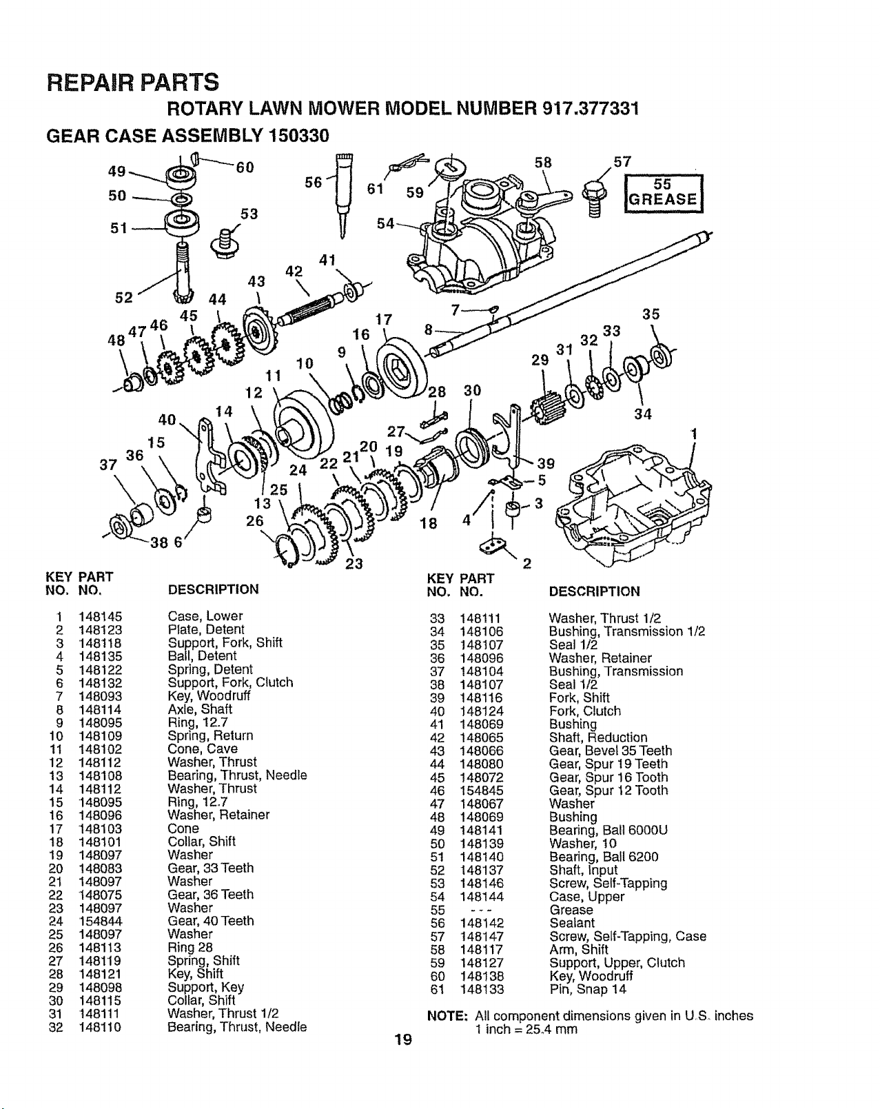
REPAIR PARTS
ROTARY LAWN MOWER MODEL NUMBER 917.377331
GEAR CASE ASSEMBLY 150330
10
I 1
12
40,
15
37
38 6
25
13
26
41
KEY PART
NO. NO. DESCRIPTION
61 59
58 57
_ 55 ¸_IGREASE!
16
23
17
18
KEY
NO.
35
33
3
29
30
34
1
4"1
PART
NO. DESCRIPTION
1
2
3
4
5
6
7
8
9
10
tt
12
13
14
15
16
17
t8
19
20
21
22
23
24
25
26
27
28
29
30
31
32
148145
148123
148118
148135
148122
148132
148093
148114
148095
148109
148102
148112
148108
148112
148095
148096
148103
148101
148097
148083
148097
148075
148097
154844
148097
148113
148119
148121
148098
148115
148111
148110
Case, Lower
Plate, Detent
Support, Fork, Shift
Ball, Detent
Spring, Detent
Support, Fork, Clutch
Key, Woodruff
Axle, Shaft
Ring, 12.7
Spring, Return
Cone, Cave
Washer, Thrust
Bearing, Thrust, Needle
Washer, Thrust
Ring, 12.7
Washer, Retainer
Cone
Collar, Shift
Washer
Gear, 33 Teeth
Washer
Gear, 36 Teeth
Washer
Gear, 40 Teeth
Washer
Ring 28
Spring, Shift
Key, Shift
Support, Key
Collar, Shift
Washer, Thrust 1/2
Bearing, Thrust, Needle
19
33 148tll Washer, Thrust 1/2
34 148106 Bushing, Transmission 1/2
35 148107 Seal 1/2
36 148096 Washer, Retainer
37 148104 Bushing, Transmission
38 148107 Seal 1/2
39 148116 Fork, Shift
40 148124 Fork, Clutch
41 148069 Bushing
42 148065 Shaft, Reduction
43 148066 Gear, Bevel 35 Teeth
44 148080 Gear, Spur 19 Teeth
45 148072 Gear, Spur 16 Tooth
46 154845 Gear, Spur 12 Tooth
47 148067 Washer
48 148069 Bushing
49 148141 Bearing, Bali6000U
50 148139 Washer, t0
51 148140 Bearing, Ball 6200
62 148137 Shaft, Input
53 148146 Screw, Self-Tapping
54 148144 Case, Upper
55 - - - Grease
56 148142 Sealant
57 148147 Screw, Self-Tapping, Case
58 148117 Arm, Shift
59 148127 Support, Upper, Clutch
60 148138 Key, Woodruff
61 148133 Pin, Snap 14
NOTE: All component dimensions given in US. inches
1 inch = 25°4 mm
_4
C_
Lt_
B
LU
2O
I-
tl:
n-
u
tO
o_
l'.-
iI:
ILl
Z
_1
ill
0
0
l,LI
0
Z
-i
>.
0
iv"
Z
o
I-
o
ill
<o
n
>.
,,,6
_z
Z
0
F"
eL
o
_0
ill
D
l-
<g
ll.
l.l.I0
_z
"--" CO
v- ,,r- (._
x_
,..j _ o
×_
qJm
•1D Irj rn _:_
2_cYO t-
_ _._ m_ -a- _ =
x x x
___.__
_0_
_._o _ _ _o_,_. .___o _,
L2
(D
0
E
_: .'-T. o
.N'--
ill .w 0 -l_
o_mNm
r-_O_
mOu-oO0_O
m
o
<
&ll
21
c'J
Ill
In
Z
-I
Ill
0
0
Z
=.I
>.
0
g_
I
ILl
aD
.............
/
\
22

•"" ..C,
v
>, _>,
l:C
,It-=
t_
rr
ill
Z
-I
LU
C_
0
0::
ILl
0
Z
_1
0
z
_.9_
t-
0
ILl
I--
_z
_d
_z
z
.9.o
!-
0
ILl
O0 _
XX
_oo__oo_o_ _ _o
co
x
E
>,_ , .__n .=__ "=
_Zm_Z_NZ:_mm_m_n
o
o
o
_ 0_
_o_oo_
°°
,_d
_z
23
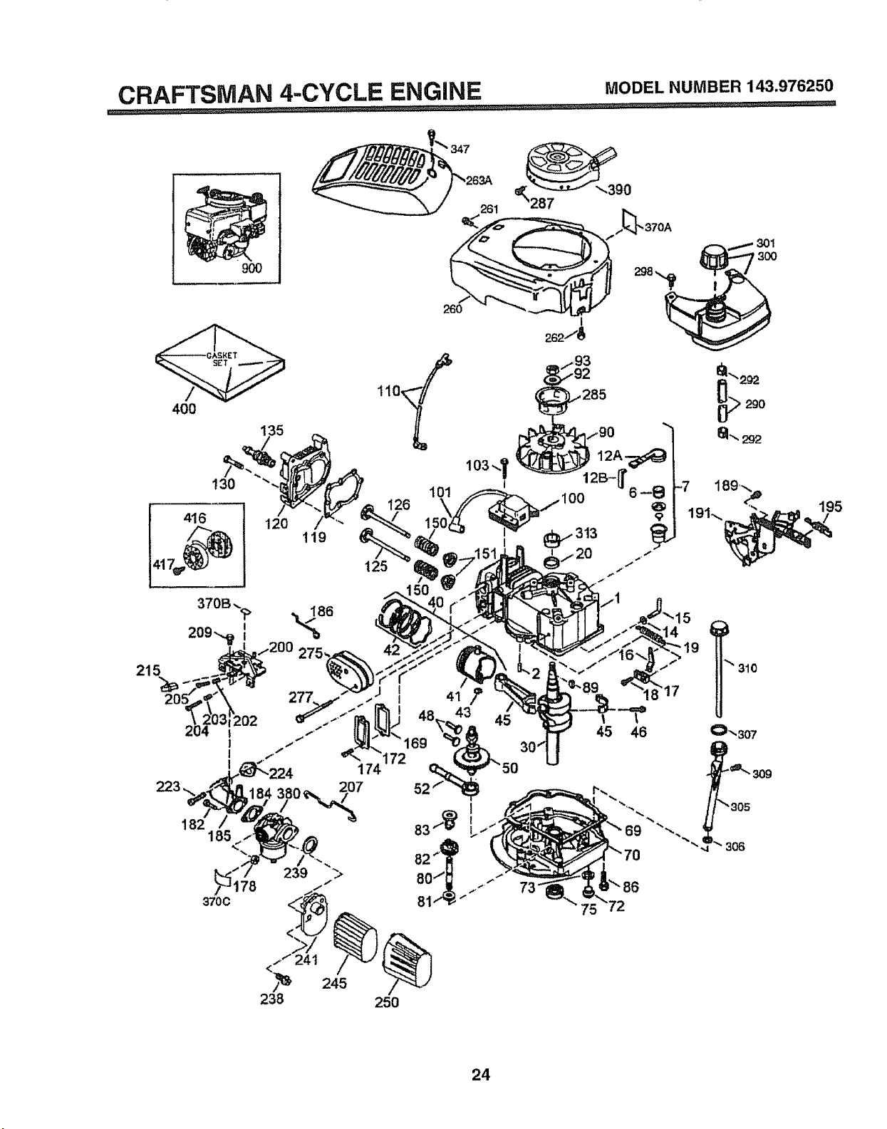
CRAFTSMAN 4-CYCLE ENGINE MODELNUMBER143.976250
............. _,
9O0
400
416
lo3,,,,i,
130 d
119
120
_285
370C
t
45 46
69
"'292
61..,292
310
24
CRAFTSMAN 4-CYCLE ENGINE MODELNUMBER143.976250
KEY PART KEY PART
NO. NO. DESCRIPTION NO. NO. DESCRIPTION
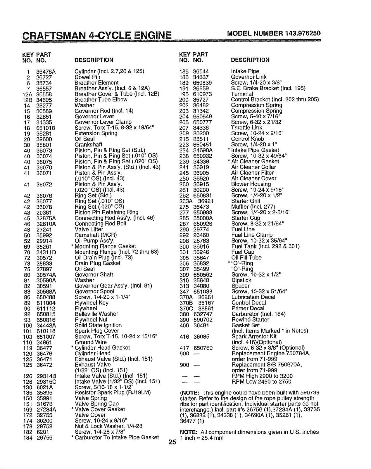
1 36478A
2 26727
6 33734
7 36557
12A 36558
12B 34695
14 28277
15 30589
16 32651
17 31335
18 651018
19 36281
20 32600
30 35801
40 36073
40 36074
40 36075
41 36070
41 36071
41
42
42
42
43
45
46
48
5O
52
69
70
72
73
75
8O
81
82
83
86
89
90
92
93
100
101
103
t10
119
120
125
125
126
126
130
135
150
151
169
172
174
178
182
184
36072
36076
36077
36O78
20381
32875A
32610A
27241
35992
29914
35261
34311D
30572
28833
27897
30574A
30590A
30591
30588A
650488
611OO4
611112
65O815
650816
34443A
610118
6510O7
34961
36477
36476
36471
36472
29314B
29315C
6021A
35395
35991
31673
27234A
32755
30200
29752
6201
26756
Cylinder (IncL 2,7,20 & 125)
Dowel Pin
Breather Element
Breather Ass'yo (IncL 6 & 12A)
Breather Cover & Tube (IncL 12B)
Breather Tube Elbow
Washer
Governor Rod (incl. 14)
Governor Lever
Governor Lever Clamp
Screw, Torx T-15, 8-32 x 19/64"
Extension Spring
Oil Seal
Crankshaft
Piston, Pin & Ring Set (Std.!,
Piston, Pin & Ring Set (o010 OS)
Piston, Pin & Ring Set(..020" OS)
Piston & Pin Ass y. (Std.) (Incl. 43)
Piston & Pin Ass'y.
(.010" OS) (Incl 43)
Piston & Pin Ass'y.
(.020" OS) (IncL 43)
Ring Set (Std.!
Ring Set (o010' OS)
Ring Set (.020' OS)
Piston Pin RetainingRing
Connecting Rod Ass y. (Incl. 46)
Connecting Rod Bolt
Valve Lifter
Camshaft (MCR)
Oil Pump Ass'y
* Mounting Flange Gasket
Mounting Flange (Incl. 72 thru 83)
Oil Drain Plug (incL 73)
Drain P_ugGasket
Oil Seal
Governor Shaft
Washer
Governor Gear Ass'y. (IncL 81)
Governor Spool
Screw, 1/4-20 x 1-1/4"
Flywheel Key
Flywheel
Belleville Washer
Flywheel Nut
Solid State ignition
Spark Plug Cover
Screw, Torx T-I5, 10_24x 15/16"
Ground Wire
* Cylinder Head Gasket
Cylinder Head
Exhaust Valve (Std.) (Inclo 151)
Exhaust Valve
(1/32" OS) (IncL 151)
Intake Valve (Std.!, (IncL 151)
Intake Valve (1/32 OS) (lncL 151)
Screw, 5t16-18 x 1-t/2"
Resistor Spark Plug (RJ19LM)
Valve Spring
Valve Spring Cap
* Valve Cover Gasket
Valve Cover
Screw, 10-24 x 9/16"
Nut & Lock Washer, 1/4-28
Screw, 1/4-28 x 7/8"
* Carburetor To Intake Pipe Gasket
25
185 36544 Intake Pipe
186 34337 Governor Link
189 650839 Screw, 1/4-20 x 3/8"
191 36559 S E. Brake Bracket (Inclo 195)
195 610973 Terminal
200 35727 Control Bracket (IncL 202 thru 205)
202 36482 Compression Spring
203 3!342 Compression Spring
204 650549 Screw, 5-40 x 7/16
205 650777 Screw, 6-32 x 21/32"
207 34336 Throttle Link
209 30200 Screw, 10-24 x 9/16"
215 35511 Control Knob
223 650451 Screw, 1/4-20 x 1"
224 34690A * Intake Pipe Gasket
238 650932 Screw, 10-32 x 49/64"
239 34338 * Air Cleaner Gasket
241 36919 Air Cleaner Collar
245 36905 Air Cleaner Filter
250 36920 Air Cleaner Cover
260 36915 Blower Housing
261 30200 Screw, 10-24 x 9t16"
262 650831 Screw, 1/4-20 x 1/2"
263A 36921 Starter Grill
275 36473 Muffler (Incl. 277) ,,
277 650988 Screw, 1/4-20 x 2-5/16
285 35000A Starter Cup
287 650926 Screw, 8-32 x 21/64"
290 29774 Fuel Line
292 26460 Fuel Line Clamp
298 28763 Screw, 10-32 x 35/64"
300 36916 Fuel Tank (IncL 292 & 301)
301 36246 Fuel Cap
305 35647 Oil Fill Tube
306 36832 * "O"-Ring
307 35499 "O"-Ring
309 650562 Screw, 10-32 x 1/2"
310 35648 Dipstick
313 34080 Spacer
347 651038 Screw, 10-32 x 51/64"
370A 36261 Lubrication Decal
370B 35167 Control Decal
370C 36861 Primer Decal
380 632747 Carburetor (lncl. 184)
390 590702 Rewind Starter
400 36481 Gasket Set
(lncL Items Marked * in Notes)
416 36085 Spark Arrestor Kit
(IncL 416)(Optional)
417 650760 Screw, 8-32 x 3/8" (Optional)
900 -- Replacement Engine 750784A,
order from "71-999
900 -- Replacement S/B 750670A,
order from 71-999
RPM High 2900 to 3200
RPM Low 2450 to 2750
(NOTE: This engine could have been built with 590739
starter° Refer to the design of the rope pulley strength
ribs for part identification. Individual starter parts do not
interchange°) Inc!. part #'s 26756 (1),27234A (1), 33735
(I), 36832 (1), 34338 (1), 34690A (I), 35261 (1),
36477 (1)
NOTE: All component dimensions given in U.S. inches
1 inch = 25.4 mm
CRAFTSMAN 4.-CYCLE ENGINE MODELNUMBER143.976250
dk,_zt
KEY PART
NO. NO, DESCRIPTION
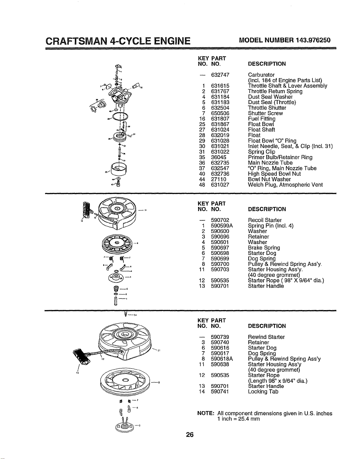
632747
1 631615
2 631767
4 631184
5 631183
6 632504
7 650506
16 631807
25 631867
27 631024
28 632019
29 631028
30 631021
31 631022
35 36045
36 632735
37 632547
40 632736
44 27110
48 631027
Carburetor
(Incl. 184 of Engine Parts List)
Throttle Shaft & Lever Assembly
Throttle Return Spring
Dust Seal Washer
Dust Seal (Throttle)
Throttle Shutter
Shutter Screw
Fuel Fitting
Float Bowl
Float Shaft
Float
Float Bowl "O" Ring
Inlet Needle, Seat, & Clip (IncL 31)
Spring Clip
Primer Bulb/Retainer Ring
Main Nozzle Tube
"0" Ring, Main Nozzle Tube
High Speed Bowl Nut
Bowl Nut Washer
Welch Plug, Atmospheric Vent
KEY PART
NO. NO. DESCRIPTION
O_;t
5907O2
1 590599A
2 590600
3 590696
4 590601
5 590697
6 590698
7 590699
8 59O7OO
11 590703
12 59O535
13 590701
Recoil Starter
Spring Pin (IncL 4)
Washer
Retainer'
Washer
Brake Spring
Starter Dog
Dog Spring
Pulley & Rewind Spring Ass'y.
Starter Housing Ass y.
(40 degree grommet) ,,
Starter Rope ( 98 X 9t64 dia..)
Starter Handle
KEY PART
NO. NO, DESCRIPTION
I_ t_1-_
590739 Rewind Starter
3 590740 Retainer'
6 590616 Starter' Dog
7 590617 Dog Spring
8 590618A Pulley & Rewind Spring Ass'y
11 590638 Starter- Housing Ass y
(40 degree grommet)
12 590535 Starter Rope ,
(Length 98" x 9/64' diao)
13 590701 Starter' Handle
14 590741 Locking Tab
NOTE: All component dimensions given in UoS, inches
1 inch = 2&4 mm
26
TROUBLESHOOTING POINTS
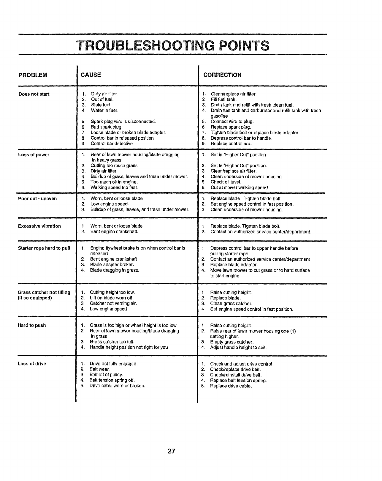
PROBI.EM
Does not start
Loss of power
Poor cut - uneven
Excessive vibration
Ul,,i,i,i , :
Starter rope hard to pull
Grass catchernot filling
(If so equipped)
Hard to push
Loss of drive
CAUSE
1.
2.,
3_,
4
5,
6
7
8.
9.
1.
2_
3.
4.
5o
6
1,,
2.
3,,
I,
2.,
1
2
3.
4,
Dirty air filter,
Out of fuel
Stale fuel
Water in fuel,
Spark p{ug wire ts dlsconnecled
Bad spark plug
Loose blade or broken blade adapter
Contro{ bar in released position
Control bar defective
Rear of lawn mower housing/blade dragging
in heavy grass.
Cutting too much grass
Dirty air filter.
Buildup of grass, leaves and trash under mower_
Too much oil in engine°
Walking speed too fast
Worn, bent or loose blade.,
Low engine speed
Buildup of grass, leaves, and trash under mower.
Worn, bent or loose blade.
Bent engine crankshaft,
Engine flywheel brake is on when control bar is
released
Bent eng{ne crankshaft
Blade adapter broken
Blade dragging in grass.
1, Cutting height too low,
2. Lift on blade worn off.
3, Catcher not venting air,,
4, Low engine speed
I. Grass is too high or wheel height is too low,
2. Rear of tawn mower housing/blade dragging
in grass,
3 Grass catcher too full
4, Handle height position not right for you
1, Drive not fultyengaged,
2. Belt wear
3, Be{t off of pulIey
4. Belt tension spring off,
5. Drive cable worn or broken.
CORRECTION
1,
2..
3.,
4.
5,
6,
7,
8
9,
1. Set in'Higher Cut" position,
Clean/replace air filter.
Ftil fuel tank.
Drain tank and refill with fresh clean fuel
Drain fuet tank and carburetor and refffl tank with fresh
gasoline,
Connect wire to plug,,
Replace spark plug,,
Tighten blade bolt or replace blade adapter
Depress control bar to handle.
Replace control bar.
............. r...
2. Set In "Higher Cut" position,
3 Clean/replace alrfilter
4_ Clean underside of mower housing,,
5, Check oil kevet.
6, Cut at s!ower walking speed
,m ill i i ,1111 i,,, • LU IJ L L J
1 Replace blade, Tighten blade bolt,
2,, Set engine speed control in fast position
3 Clean underside of mower housing,
t Replace blade,, Tighten blade boll
2., Contact an authorized service center/department,
1,
2_
3,
4,
Depress control bar to upper handle before
puff{rigstarter rope,,
Contact an authorized service centerldepartment,
Replace blade adapter.
Move lawn mower to cut grass or to hard surface
to start engine
t, Raise culling height,
2 Replace blade_
3. Clean grass catcher
4, Set engine speed control in fast position°
I Raise cu_Jng height.
2, Raise rear of Fawn mower housing one (1)
setting htgher,
3 Empty grass catcher.
4 Adjust handle height to suit
1,, Check and adjust drive control,
2. Check/replace drive belt.
3 ChecWre{nstal{ drive boil
4_ Replace belt tension spring,,
5. Replace drive cable,
27
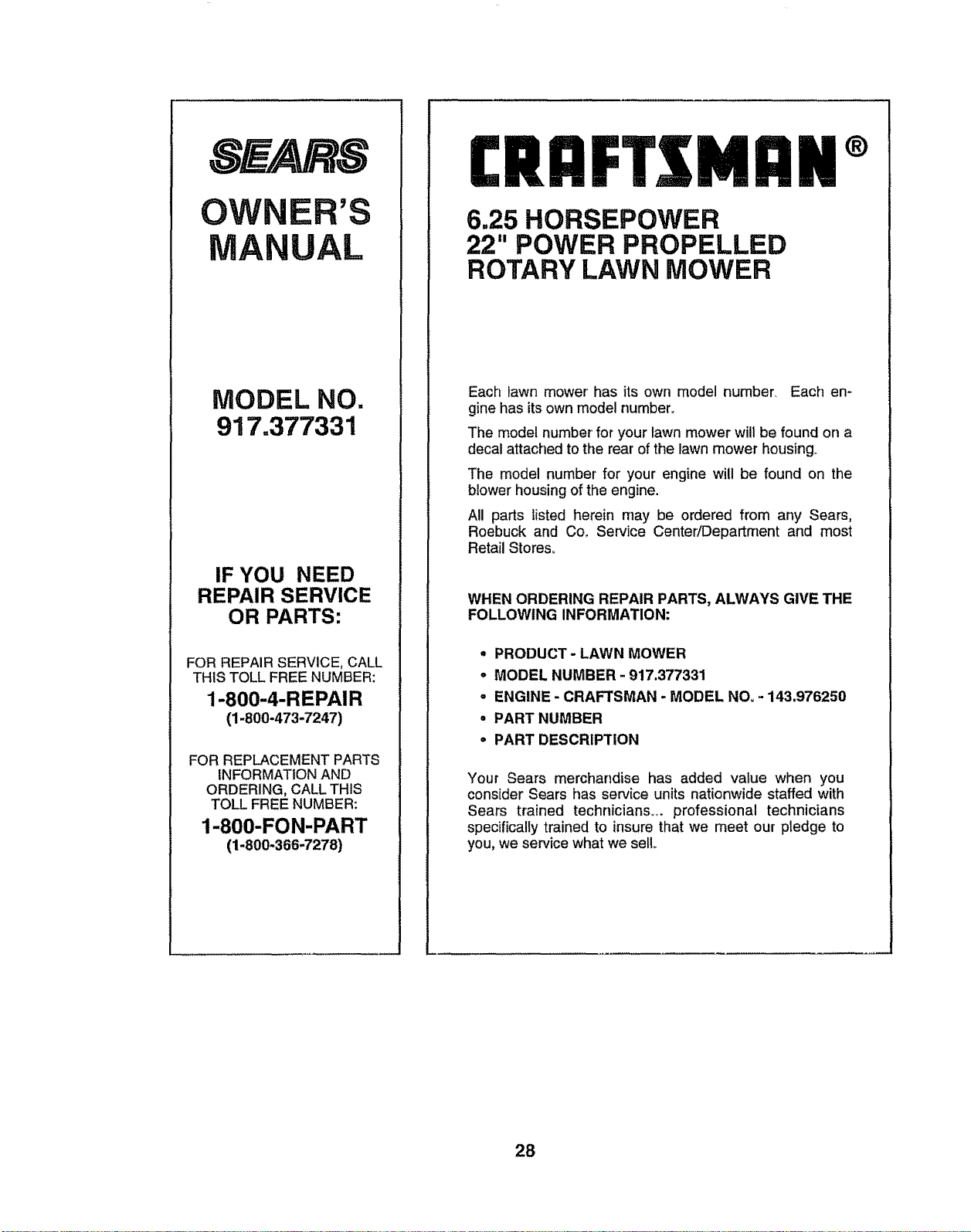
OW R'S
MANUAL
MODEL NO.
917.377331
IF YOU NEED
REPAIR SERVICE
OR PARTS:
FOR REPAIR SERVICE, CALL
THIS TOLL FREE NUMBER:
1-800-4-REPAIR
(1-800-473-7247)
FOR REPLACEMENT PARTS
INFORMATION AND
ORDERING, CALL THIS
TOLL FREE NUMBER:
1-800-FON-PART
(1-800-366-7278)
I:RRFT3 MRN®
6.25 HORSEPOWER
22" POWER PROPELLED
ROTARY LAWN MOWER
Each lawn mower' has its own model number. Each en-
gine has its own model number.
The model number' for your lawn mower will be found on a
decal attached to the rear of the lawn mower housing.
The model number for your engine will be found on the
blower housing of the engine.
All parts listed herein may be ordered from any Sears,
Roebuck and Co_. Service Center/Department and most
Retail Stores°
WHEN ORDERING REPAIR PARTS, ALWAYS GIVE THE
FOLLOWING INFORMATION:
,, PRODUCT- LAWN MOWER
,, MODEL NUMBER - 917.377331
• ENGINE - CRAFTSMAN - MODEL NOo - 143.976250
o PART NUMBER
• PART DESCRIPTION
Your Sears merchandise has added value when you
consider Sears has service units nationwide staffed with
Sears trained technicians., professional technicians
specifically trained to insure that we meet our pledge to
you, we service what we sell
28
CROFTS
MODELO NO. 917.377331
®
MANUAL DEL DUENO
• Montaje
, Operacibn
, Responsabilidades
del Cliente
, Servicio
, Ajustes
• Partes de Repuesto
Precauci6n:
Lea y siga todas
las reglas e
intrucciones de
seguridad antes de
operar este equipo.
160912 O&O&97 VBL
IMPRESO EN LOS ESTADOS UN1DOS
IIIIIIIIIIIIIIIIIIIII IIIlUlIIIII IIIIII/111111111111III
REGLAS DE SEGURIDAD
Prdcticas de Operaci6n Seguras para las Segadoras
IMPORTANTE: ESTA MAQUINA CORTADORA ES CAPAZ DE AMPUTAR LAS MANES Y LOS PIES Y DE LANZAR OBJETOS.
SI NO SE OBSERVAN LAS INSTRUCCIONES DE SEGURIDAD SIGUIENTES SE PUEDEN PRODUCIR LESIONES GRAVES O
LA MUERTE.
LOS ESTANDARES DE SEGURIDADEXIGENLAPRESENCIADELOPERADORENLOSCONTROLESPARAREDUCIRA UN MINIMOELRIESGO
DELESIONARSE.SU UNIDADVIENE EQUIPADACON DICHOSCONTROLES,PeR NINGUNMOTiVe TRATE DE ELIMINARLA FUNCI(_NDE LOS
CONTROLES QUE EXIGEN LA PRESENCIA DEL OPERADOR.
ENTRENAMIENTO:
- Lea este manual del operador cuidadosamente. Familiafice-
secontos controlesyaprenda a operarsu segadora enforma
adecuada_ Aprenda a parar su segadora rdpidamente
• No permita que los niSos usen su segadoraoNunca permita
que fos adultos operen la segadora sin contar con las
instrucciones adecuadae..
° Mantenga el drea de operaci6n despejada de gente, espe-
cialmente de nifios pequefios y de animales domdsticos.
. Use la segadora solamente para los fines propuestos per et
fabricante y seg_n las exp!icaciones descritas en este ma-
nual.
• No opere la segadora sise ha cafdo o dafiado en cualquiera
forma Siempre repare los dafios antes de usarla.
• No use accesorios que no hayan side recomendados per el
fabflcante,. El use de dichos accesorios puede ser peligroso.,
. La cuchilla gira cuando el motor est_ funcionando.
PREPARACI6N:
• Siempre revise cuidadosamente el _rea que se va a segar y
desp_jela de todas las _piedras, palos, alambres, huesos y
otros objetos extrafios, Estos objetos saran fanzados con ta
cuchiUa y pueden producir lesiones graves..
• Siempre use anteojos de seguridad o protectores de ojos
cuando arranque y durante e! tiempo qua use ta segadora
o Vtstase en forma adecuada. No opere la segadora sin
zapatos o con sandalias abiertas+ Use solamente zapatos
s6fldos con buena tracci6n cuando siegue,
• Revise el estanque de combustible antes de hacer arrancar
el motor. No Ilene el estanque de gasolina en recintos
cerrados, ni cuando el motor est_ funcionando o cuando est&
caliente.. Permita que el motor se enfrfe per varies minutes
antes de tlenar el estanque de gasofinao Limpie toda la
gasolina derramada antes de hacer arrancar el motor..
. Siempre haga los ajustes de altura de las ruedas antes de
hacer arrancar su segadora. Nunca trate de hater _sto
mientras qua el motor est& func|onando.
° Siegue siempre durante el dfa o con buena luz artificial.
OPERACl(_N:
• Mantengasus ojos y su mente en la segadorayen el drea que
se est_ cortando. No permita que otros intereses io distrai-
gan.
° No corte c6sped mojado o resbatose. Nunca corra mientras
est_ operando su segadora. Siempre asegQrese de manta-
her el equilibrio - mantenga el mango agarrado firmemente
y cammeo
• No ponga las manes o los pies cerca o debajo de las partes
rotatorias. Mant_ngase alejado de la abertura de desearga
en todo memento.
° Siempre pare el motor cuando se vaya o cuando no est_
usando su segadora, o antes de atravesar las entradas para
autos, los senderos, caminos y _.reas cubiertas de ripio.
- Nunca dirija ta descarga del matedal hacia los espectadores
ni permita a nadie cerca de la segadora mientras la est6
operando.
. Antes de limpiar, inspeccionar o de reparar la segadora, pare
el motor y est_ completamente seguro de clue la cuchilla y
qua todas las partes que se mueven se hayan detenido.
Luego, desconecte el alambre de la bujfa y mant_ngalo
alejado de _.sta para evitar el arranque per accidente°
• No continue hacienffo funcionar su segadora sile pega a un
objeto extrafio. Siga el procedimiento descrito anteriormen-
te, tuego repare cualquier dafio antes de volver a arrancar y
de operar su segadora.+
. No cambie los ajustes del regulador o haga que el motor ande
a una velocidad excesiva. Se pueden producir dafios en el
motor y lesiones personales.
• No opera su segadora si vibrafuerade 1onormal, La vibraci6n
excesiva es una indicaci6n de dafio; pare el motor, revise en
forma segura la causa de la vibraci6n yhaga las reparactones
segun sea necesano.
o No haga funcionar el motor en recintos cerrados. Los gases
de escape son peligrosos.
• Nunca corte el c_sped tirando la segadora hacia usted_
Siegue a trav_s de la cara de las pendientes, nunca hacia
arriba o hacia abajo pues puede perder el equilibrio. No
siegue pendientes demasiado empinadas, Tonga cuidado
cuando opera la segadora en terreno disparejo o cuando
cambie de direcci6n - mantenga un buen equilibrio
• Nunca opere ta segadora sin las protecciones adecuadas,
las planchas, el recogedor de c_sped y otros disposilivos de
seguridad en su lugar.
MANTENIMIENTO Y ALMACENAMIENTO:
• Revise la cuchilla y los pernos de montaje del motor a
menudo, para asegurarse que estdn apretados en la forma
adecuada_
° Revise todos los pemos, tuercas y tomillos a intervalos
frecuentes, para verificar si estdn apretados en forma ade-
cuada, y asegurarse que [a segadora se encuentra en
condioiones de funcionamiento seguro.
• Mantenga todos los dispositivos de segufidad en su lugar y
listos para funcionar,.
• Para reducir et peligro de incendio, mantenga el motor sin
c@sped,hojas y grasa o aceite en exceso.+
° Revise el recogedor de c_sped amenudo paraverificar si hay
deterioro y desgaste y cambie las bolsas desgastadas. Use
solamente las bolsas de repuesto recomendadas per el
fabricante de su segadora o qua cumplen con tas especifica-
ciones de @ste_
° Siempre mantenga una cuchilla afilada en su segadora
• Siempre permita qua el motor se enfrfe antes de guardafla en
cualquier recinto cerrado..
• Nunca guarde la segadora con combustible en et estanque
dentro de un edificio en donde los gases pueden alcanzar
una llama expuesta o una fuente de ignici6n, tal come el
calentador de agua, la estufa de calefacci6n, la secadora de
ropa, etc,
Busque este sfmbolo que sefiala las pre-
cauciones de segur|da.d de impor.tancia.Quiere decir- |ilATENCIONfff IIIESTEALER-
TOtt! SU SEGURIDAD ESTA COMPROME-
TIDA.
IIIU ; ;i_11 '1'11'11'1 / .............
PRECAUCION: Siempre desconecte el alam-
bre de la bujfa y p6ngalo deride no pueda
entrar en contacto con la bujfa, para ev|tar el
arranque per accidente, durante la prepara-
ci6n, el transporte, el ajuste o cuando se
hacen reparaclones.
i ............................ i I'111
II I1'1111 "" '1 I "U ..... '1'1'111III1' [
A PRECAUCI(SN
Es conocido per el Estado de California qua
los gases de escape del motor de este produc-
tor contienen quimicos los cuales a ciertos
niveles, pueden ocasionar, cancer, defectos
de nacimiento, y otros da_os al sistema
reproductive.
2
FELICITACIONES porla comprade su segadora Sears Craftsman,,
Ha sido disefiada, planiticada y fabricada para darle la major
confiabitidad yet me]or rendimiento posibles.
En el caso de que se encuentre con cualquier problema qua no
pueda solucionar f&cilmente, haga el favor de ponerse en contac-
to con su CentrolDepartamento de Servicio Sears m&s cercano.
Sears cuenta con t&cnicos bien capacitados y competentes y con
tas herramientas aclecuadas para darle servicio o para reparar su
unidad,.
Haga el favor de leer y de guardar este manual. Estas instruccio-
nes le permitir&n montar y mantener su segadora en torma
adecuada Siempre observe las "REGLAS DE SEGURIDAD.,"
NOMERO DE
MODELO
NOMERO DE
SERIE
917.377331
FECHA DE
COMPRA
EL NUMERO DEL MODELO Y EL DE SER1E SE ENCUEN-
TRAN EN LA CALCOMANIA ADJUNTA A LA PARTE TRA-
SERA DE LA CAJA DE LA SEGADORAo
DEBE REGISTRAR TANTO EL NUMERO DE SERtE COMO
LA FECHA DE COMPRA Y MANTENGALOS EN UN LU_
GAR SEGURO PARA REFERENCIA EN EL FUTURO.,
ESPECIFICACIONES DEL PRODUCTO
CABALLOS DE FUERZA: 6°25
DESPLAZAMIENTO: 12.,56 cu, inn
i CAPACtDAD Y TIPO 1_5Cuartos
DE GASOLINA: REGULAR SIN PLOMO
TIPO DE ACEITE: SAE 30 (sobre 32°F)
(API-SF/SG/SH) SAE 5W-30 (debajo 32°F)
CAPACIDAD DE ACEITE: 20 oz, de capacidad
BUJIA: CHAMP1ON RJ19LM
(ABERTURA: .030")
TOLERANClA DE
VALVULA:
ADMISION: .004"-,008"
DESCARGA:, 004" - ,008"
., i
ENCENDIDO DE
ESTADO SOLIDO
ABERTURADEAIRE: ,,0125ino
TORSION DELPERNO 35-40FTLBS_(P1ESLfBRA)
DE LACUCHILLA:
ACUERDO DE MANTENIMIENTO
Este producto incluye un Acuerdo de Mantenimiento Sears. P6ngase en contactoconsu tienda Sears m&s cercana para informarse sobre
los deta!leso
RESPONSABILIDADES DEL CLIENTE
• Lea y observe las reglas de seguridad.
• Siga un programa regular de mantenimiento, cuidado y uso de su segadora..
• Siga las instruccionesdescritas en las secciones "Responsabilidades det Ctiente" y "Almacenamiento" de este Manual dal Duefio.
GARANTfA LIMITADA DE DOS AltOS PARA LA SEGADORA
A MOTOR CRAFTSMAN
Pot dos (2) afios, a partir de la fecha de compra, cuando esta Segadora Craftsman se mantenga, lubrique y afine segen las
instrucciones para la operaci6n y el mantenimiento en el manual del dueSo, Sears reparar_ gratis todo defecto en el material y la
mano de obra.
Si ta Segadora Craftsman se usa para fines comerciates o de arriendo, esta garantfa sSIo se aplica pot noventa (90) dt'asa partir
de la fecha de comprao
Esta Garantfa no cubre:
• Articulos que se desgastan duranteel uso normal tales corno las cuchillas segadoras rotatorias, los adaptadores de ta cuchilta,
las correas, los filtros de aire y las buj_as
• Reparaciones necesarias debido at abuso o a la negligencia del operador, inc|uy_ndosea los cig_ieSalesdoblados y a la falta
de mantenimiento del equipo seg_n las instruccionesque se incluyen en el manual del due5o_
EL SERVICIO DE GARANTIA ESTA DISPON1BLE AL DEVOLVER LA SEGADORA A MOTOR CRAFTSMA_ AL CENTRO/
DEPARTAMENTO DE SERVICIO SEARS M/_S CERCANO EN LOS ESTADOS UNIDOS ESTA GARANTIA SE APL1CA
SOLAMENTE MIENTRAS EL PRODUCTO ESTE EN USO EN LOS ESTADOS UN1DOS,,
Esta Garantla le otorga derechos legales especfficos, y puede qua tambi_n tenga otros derechos qua var[an de estado a estado.
SEARS, ROEBUCK AND CO,, D/817 WA, HOFFMAN ESTATES, ILLINOIS 60179
3
TABLA
REGLAS DE SEGUR|DAD ............................................ 2
ESPECIFICACIONES DEL PRODUCTO ...................... 3
RESPONSABILIDADES DEL CLIENTE ............ 3, 12-15
GARANT(A .................................................................... 3
MONTAJE ...................................................................... 6
OPERACI(SN ............................................................ 8-11
PROGRAMA DE MANTENIMIENTO .......................... 12
SERVICIO Y AJUSTES .......................................... 16-17
ALMACENAMIENTO ................................................... 18
IDENTIFICAClON DE PROBLEMAS .......................... 19
PARTES DE REPUESTO .................. VEA EL MANUAL
INGLES DEL DUEllO
ORDEN DE PARTES/SERVICIO ................................ 20
|NDICE
A
Aceite:
Afmacenamiento .....................................18
Motor .................................................................9
Acuerdo de _ntenimiento .....................12
Ajustes:
Altura de corte ...............................................9
Altura de! mango ....................................17
Carburador .............................................17
Velocidad del motor ......................................9
Almacenamiento ..........................................18
Arranque del motor ....................................10
B
Bujia ........................................................................15
C
Combustible:
Almacenamiento ................................18
Capacidad ..............................................10
Tipo ..................................................................10
Control de la ve{ocidad:
Motor .....................................................................8
Controles:
Barra de control que exige la
presencia del operador- ........................8
Control de la impulsiSn .......................8
Control de la velocidad del motor .,,.8
Control de la zona del motor ..............8
Consejos para segar ..................................11
Cuohilla:
Afilamiento ............................................13
Cambio .........................................................t3
E
Especificaciones ....................................................3
F
Filtro de Aim:
Servicio .........................................................15
G
Garantia ........................................................................3
L
Lubricaci6n:
Motor .........................................................15
Segado_a ................................................12
M
Mango:
Ajuste ..........................................................17
Montaje ........................................................6
Montaje ...................................................................6
Motor:
Almacenamiento ....................................18
Arranque ...............................................11
Cambio de aceite .......................................15
Fittro de aire .............................................15
Nivel de aceite ...........................................15
Parada ................................................11
Tipo de aceite .........................................15
N
Niveles de corte .................................................9
O
Opciones:
Accesorios ..................................................5
Operaci6n:
Barra de control que exige la
presencia del operador .........................8
Control de la impulsi6n ............................8
Control dot motor ...................................8
P
Parada del motor ...........................................11
Programa de mantenimiento .....................12
R
Reglas de seguridad ........................................2
Responsabilidades del Cliente _o,3, 12-15
Bujia .............................................................15
Cuidado de la cuchilta/cambio ..... 13
FUlro de aire ...................................................15
Lubricaoi6n ..................................................12
Motor_ ...............................................................15
S
Servicio y Ajustes:
Carburadoi' ..........................................17
Control de impulsi6n .............................15
Mango ............................................................6
Protecci6n conlra la descarga ...... 15
Velocidad del motor ............................16
T
Tabla para ta identificaci6n de
problemas ...........................................................19
4
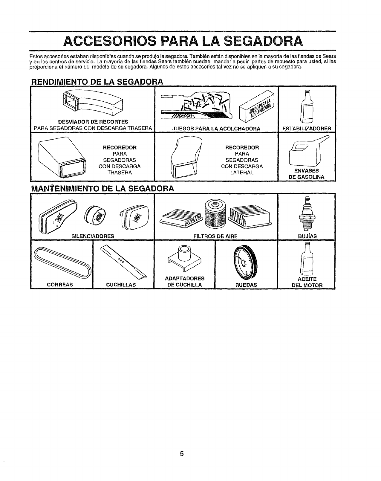
ACC PA LA SEGADORA
........................ ::::............... _ H,i,H,= - .... ....... :: ...........
Estos accesorios estaban disponibtes cuando se produjo la segadora. Tambi_n est&n disponibles en la mayoda de las tiendas de Sears
yen los centros de servicio La mayor_a de las tiendas Sears tambi_n pueden mandar a pedir partes de repuesto para usted, si ies
proporciona el nemero del modelo de su segadora, Algunos de estos accesorios tal vez no se apliquen a su segadora,
RENDIMIENTO DE LA SEGADORA
DESVIADOR DE RECORTES
PARA SEGADORAS CON DESCARGA TRASERA
ii,
J
JUEGOS PARA LA ACOLCHADORA
RECOREDOR
PARA
SEGADORAS
CON DESCARGA
TRASERA
l RECOREDOR
PARA
SEGADORAS
CON DESCARGA
LATERAL
ill t i /i ,ll,l,i
ESTABILIZADORES
ENVASES
DE GASOLINA
SILENCIADORES
CORREAS CUCHILLAS
ADAPTADORES
DE CUCH1LLA
FILTROS DE AIRE
RUEDAS _,,
BUJiAS
ACEITE
DEL MOTOR
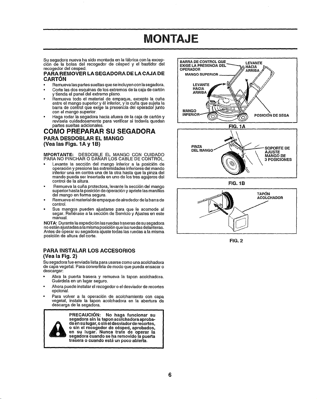
Su segadora nueva ha sido montada en la f&bdca con la excep-
ci6n de la bolsa del recogedor de c_sped y el bastidor del
recogedor de! cesped_
PARA REMOVER LA SEGADORA DE LA CAJA DE
CARTON
• Remuevalas partes sueltas que se inciuyen con iasegadora°
• Corte las dos esquinas de los extremos de la caja de cart6n
y tienda el panel def extremo piano,
• Remueva todo el mater|at de empaque, excepto |a cuSa
entre el mango superior y 6! inferior, y la cuSa que sujeta la
barra de control que exige la presencia del operador junto
con el mango superior.
• Ha_a rodar la segadora hacia afuera de la caja de cart6n y
revlsela cuidadosamente para verificar si todavi_a quedan
partes sueltas adicionales.
COMO PREPARAR SU SEGADORA
PARA DESDOBLAR EL MANGO
(Vea las Figs, 1A y 1B)
MPORTANTE: DESDOBLE EL MANGO CON CUIDADO
PARA NO PINCHAR O DANAR LOS CABLE DE CONTROL.
• Levante la secci6n del mango inferior a la posici6n de
operaci6n y presione las extremidades inferioresdot mando
inferior una en contra una de la otra hasta que la pinza del
mando pueda set insertada en uno de los tres agujeros dot
control de la aLtura.
• Remueva la cuSa protectora, levante ta secci6n dei mango
superior hasta la posici6n de operaci6n y apriete las maniflas
de/mango en forrna segura,
• Remueva ei material de empaque de alrededor de labarra de
control.
• Sus mangos pueden ajustarse para que le acemode al
segar. Refi_rase a |a secci6n de Servicio y Ajustes en este
manual
NOTA: Durante la expedici6n tas ruedas traseras de su segadora
no est&najustadas a la misma posici6n que las ruedas delanteras_
Antes de operar su segadora ajuste todas las ruedas a la misma
posici6n de altura del corte..
PARA INSTALAR LOS ACCESORIOS
(Yea la Fig. 2)
Su segadora fue enviada tistapara usarse como unaacolchadora
de capa vegetal Para convertirla de modo que pueda ensacar o
descargar:
o
Abra la puerta trasera y remueva la tapon acoichadora.
Gu&rdeta en un lugar seguro.
Ahora puede instalar el recogedor o el desviador de recortes
opcional.
Para velvet a la operaci6n de acolchamiento con capa
vegetal, instale la tapon acolchadora en ta abertura de
descarga de ta segadorao
PRECAUCI6N: No haga funcionar su
segadora sin ta tapon acolchadora aproba-
_ aen sulugar, o sln el desviador de recortes,
o sin el recogedor de c_sped, aprobados,
en su iugaro Nunca trate de operar la
segadora cuando se ha removido la puerta
trasera o cuando estd un poeo abiertao
BARRA DECONTROL QUE
EXIGELAPRESENCIA
OPERADOR
MANGO SUPERIOR
LEVANTE
HACIA
ARRIBA
LEVANTE
MANGO
POSICION DE SEGA
FIG. 1A
PINZA
_OPORTE DE
AJUSTE
MANGO DE
3 POSICtONES
FIG. 1B
TAP6N
AOOLCHADOR
FIG, 2
6
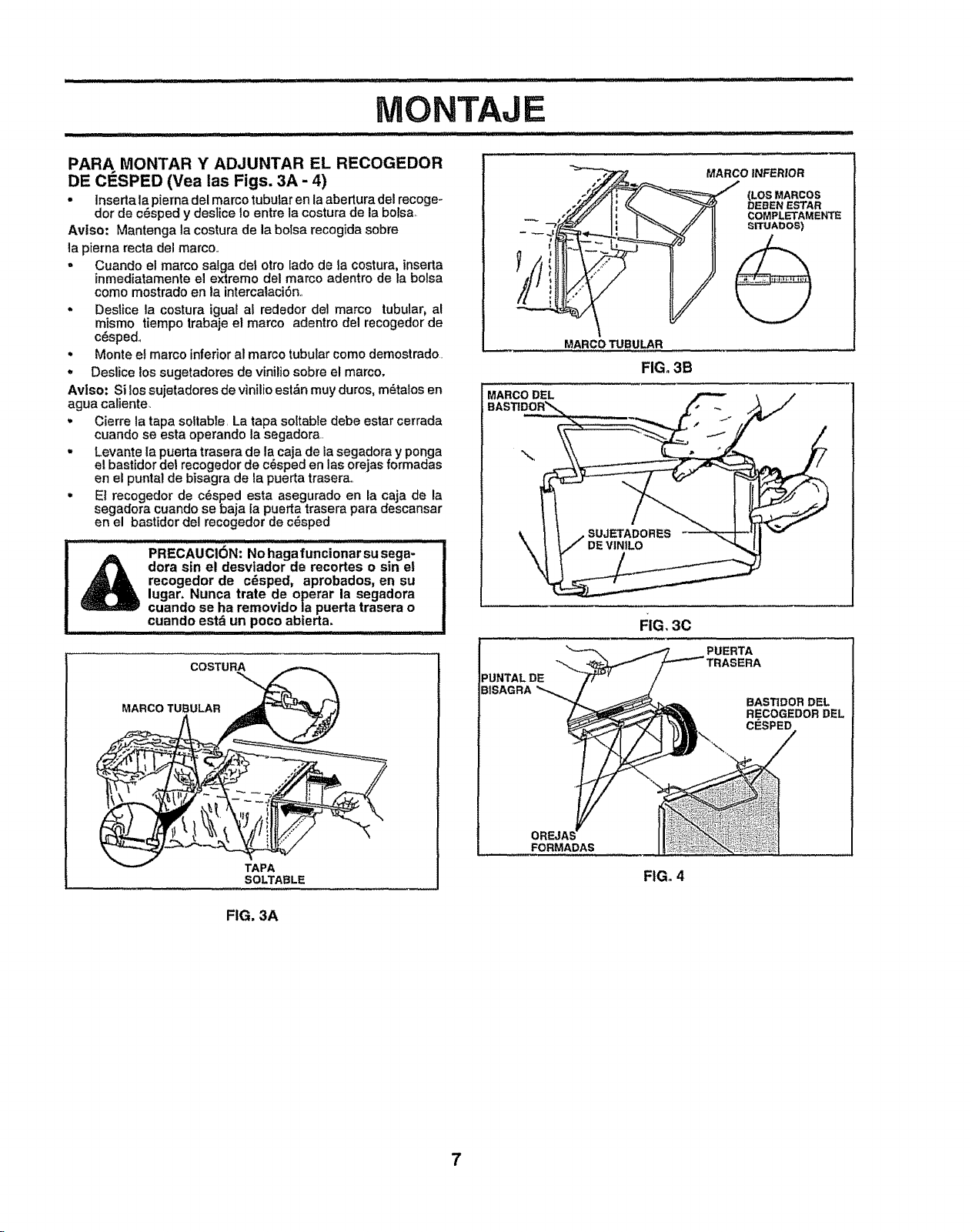
IVIONTAJE
PARA MONTAR Y ADJUNTAR EL RECOGEDOR
DE CESPED (Vea las Figs. 3A - 4)
• Inserta la pierna del marco tubular en la abertura del recoge-
dor de c_sped y deslice to entre la costura de la bolsa,
Avtso: Mantenga la costura de la bolsa recogida sobre
la pierna recta del marco°
- Cuando el marco salga del otto [ado de la costura, inserta
inmediatamente el extremo del marco adentro de la bolsa
como mostrado en la intercaiaci6n,
. Desiice la costura igual al rededor del marco tubular, al
mismo tiempo trabaje et marco adentro del recogedor de
c6spedo
• Monte et marco inferior al marco tubular como demostrado.
. Deslice los sugetadores de vinilio sobre el marco.
Avlso: Si lossujetadores de vinilio est,_n muy duros, m_talos en
agua caliente.
. Cierre la tapa soltabie, La tapa soltable debe estar cerrada
cuando se esta operando la segadora.,
- Levante la puerta trasera de la caja de la segadora y ponga
el bastidor de1recogedor de c_sped en las orejas formadas
en el punta! de bisagra de la puerta trasera,_
,' E1recogedor de c_sped esta asegurado en la caja de la
segadora cuando se baja la puerta trasera para descansar
en el bast|dor del recogedor de c_sped
PRECAUCi6N: No haga funcionar su Sega-
dora sin el desvlador de recortes o sin et
recogedor de cdsped, aprobados, en su
lugar. Nunca trate de operar la segadora
cuando se ha removido la puerta trasera o
cuando estd un poco abterta.
i,ii iii, I i iiiiii i_1
TAPA
SOLTABLE
__ ..___._ MARCO INFERIOR
o-_ _ (LOSMARCOS
.._P'x _ ; ((. _ DEEIEN ESTAR
,_ li _ //11 COMPLETAMENTI_
-:'.Y_" I= I _ // I[ _rruAboS)
MARCO TUBULAR
FIG. 3B
MARCO DEL
PUNTAL DE
BISAGRA
FIG, 3c
PUERTA
BAST1DOR DEL
RE COGEDOR DEL
CESPED
FORMADAS
FIG. 4
FIG. 3A
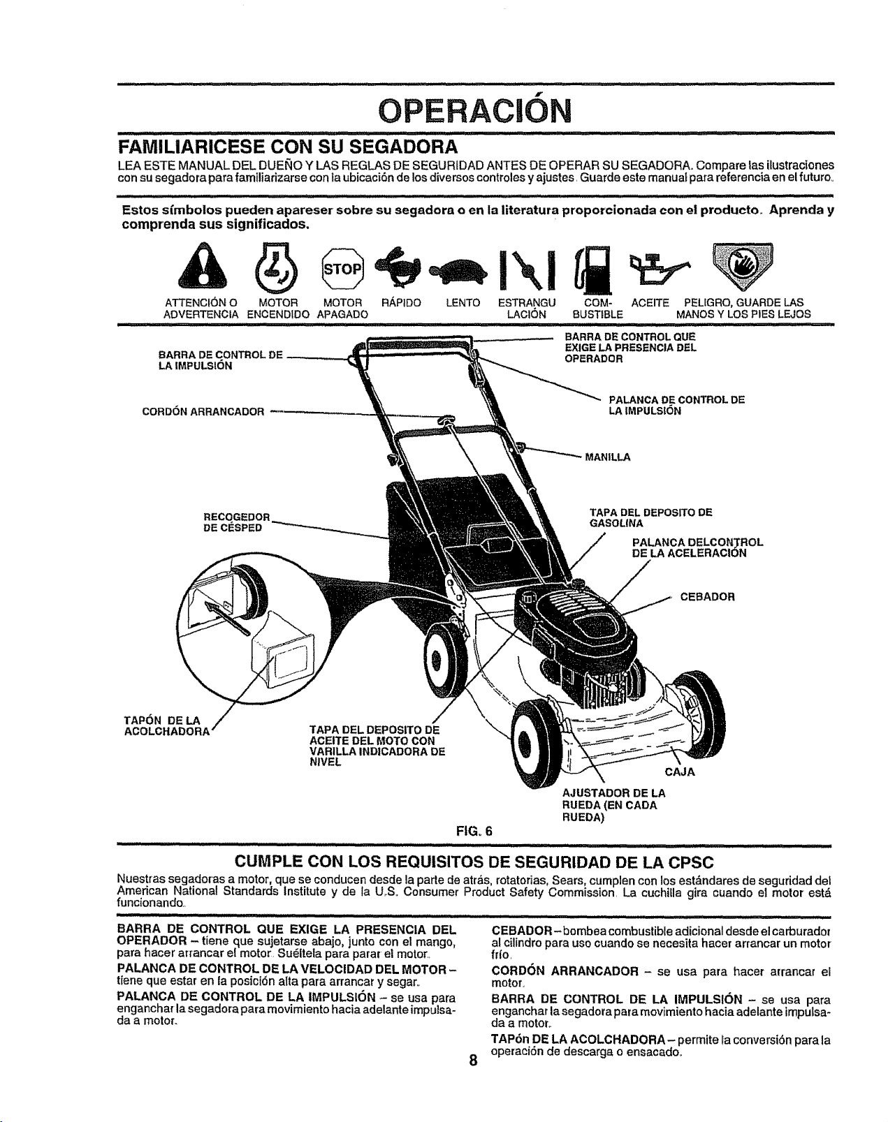
f
OPERACION
FAMILIARICESE CON SU SEGADORA
LEA ESTE MANUAL DEL DUENO Y LAS REGLAS DE SEGURIDAD ANTES DE OPERAR SU SEGADORA_ Compare las ilustraciones
con su segadora para familiadzarse con la ubicaci6n de los diversos controles y ajustes Guarde este manuaf para referencia en el futuro_
Estos s_mbolos pueden apareser sobre su segadora o en la literatur a proporcionada con el producto.. Aprenda y
comprenda sus significados.
ATTENC!ONO MOTOR MOTOR RAPIDO LENTO ESTRANGU COM- ACEITE PEUGRO,GUARDELAS
ADVERTENCIA ENCENDIDO APAGADO LACION BUST|BLE MANOSY LOSPIES LEJOS
BARRA DE CONTROL QUE
BARRA DE CONTROL EXIGE LA PRESENCIA DEL
LA IMPULSI6N OPERADOR
CORD6NARRANCADOR
PALANCA DE CONTROL DE
LAIMPULSION
MANILLA
DE
TAPA DEL DEPOS_O DE
GASOLINA
PALANCA DELCON_ROL
DE LAACELERACION
CEBADOR
TAPON DE LA
ACOLCHADORA'
TAPA DELDEPOSITO DE
ACEITE DEL MOTO CON _--'-
VARILLAINDICADORA DE
NIVEL
CAJA
AJLISTADORDE LA
RUEDA (EN CADA
RUEDA)
FIG. 6
m
CUMPLE CON LOS REQUISITOS DE SEGURIDAD DE LA CPSC
Nuest_as segadoras a motor, que se conducen desde la parte de atr&s, rotatorias, Sears, cumplen con los estdndares de seguridad det
American National Standards institute y de Ia U.S. Consumer Product Safety Commission. La cuchifla gira cuando et motor estd
funcionando..
BARRA DE CONTROL QUE EXIGE LA PRESENCIA DEL
OPERADOR - tiene que sujetarse abajo, junto con el mango,
para hacer arrancar el motor. Su_ltela para parar el motor..
PALANCA DE CONTROL DE LA VELOCIDAD DEL MOTOR -
tiene que estar en la posioi6n alta para arrancar y segaro
PALANCA DE CONTROL DE LA IMPULSION - se usa para
enganchar la segadora para movimiento hacia adelante impulsa-
da a motor.
8
.............................. ii illlll/1/ii.-....::.. ,_ ....... i ii ,, ii I ILl•
CEBADOR-bombea combustible adicional desde el carburador
a! cilindro para uso cuando se necesita hacer arrancar un motor
frio.
CORDON ARRANCADOR - se usa para hacer arrancar el
motor.
BARRA DE CONTROL DE LA IMPULSION - se usa para
enganchar la segadora para movimiento hacia adelante impu_sa-
da a motor,.
TAP6n. DE LA ACOLCHADORA- permite la conversi6n para la
operacton de descarga o ensacado.
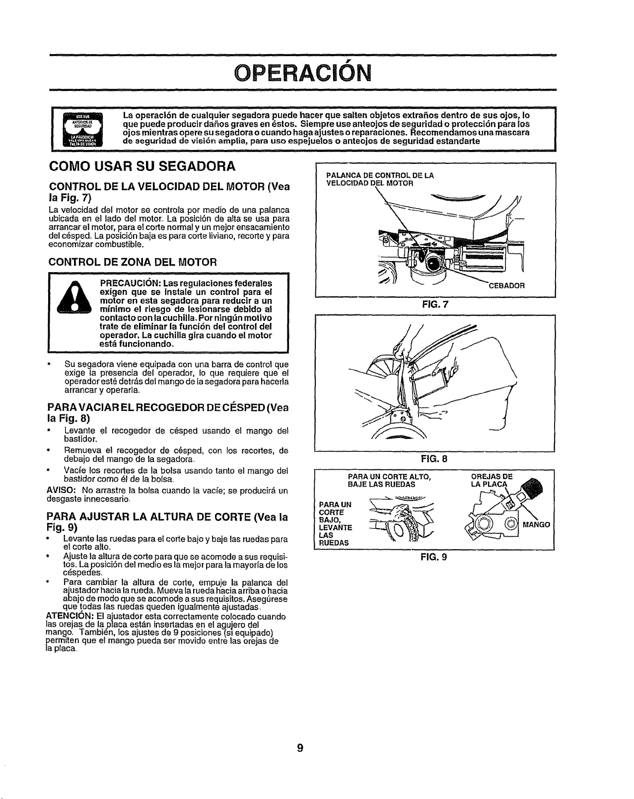
f
ACION
! ; La °perac|6n de cua_qu_'er segad°r_ puede hacer que saiten °_jet°s exiran°s dentr° da sus _0sl I°
que puede productr daSos graves en _stos. Siempra use anteojos de seguridad o protecct6n para los
ojos mientras opere su segadora o cuando hagaajustes o reparaciones. Recomendamos una mascara
de seguridad de visi6n amptia, pare use espejuetos o anteojos de seguridad estandarte
COMO USAR SU SEGADORA
CONTROL DE LA VELOCIDAD DEL MOTOR (Vea
la Fig. 7)
La velocidad del motor se controla per med{o de una palanca
ubicada en el lade del motor. La posiciSn de alta se usa pare
arrancar el motor, para el corte normal y un meier ensaeamiento
del c_sped,, La posiciSn baja es para corte liviano, recorte y para
econemizar combustible.
CONTROL DE ZONA DEL MOTOR
PRECAUCION: Las regutaciones federales
exigen que se Instale un control pare el
motor en esta segadora pare reductr a un
minimo el riesgo de lesionarse debldo at
eontacto con la cuchilla. Per ningdn motive
trate de eliminar la funci6n del control del
operador. La cuchilla gira cuando el motor
estd functonando.
..................... ,,,,,,,;:...........
&
• Su segadora viene equipada con una barra de control que
exige ta presencia del operador, Io que requiem que el
operador est_ detr&s del mango de la segadora para hacerla
arrancar y operarla_
PARA VACIAR EL RECOGEDOR DE CESPED (Vea
la Fig. 8)
• Levante el recogedor de e6sped usando el mango del
bastidor.
- Remueva el recogedor de c_sped, con los recortes, de
debajo del mango de la segadora,
• Vac{e los recortes de la boise usando lento el mango def
bastidor come _1 de ta boise.,
AVISO: No arrastre la bolsa cuando ta vacfe; se producir_ un
desgaste innecesario,
PARA AJUSTAR LA ALTURA DE CORTE (Vea la
Fig. 9)
. Levante las ruedas para eEcorte bajo y baje las ruedas pare
el eorte alto,,
• Ajuste la altura de corte para que se acomode a sus requisi-
tes,,La posiciSn del med_o es la meier pare la mayorfa de los
c_speoes.
• Para cambiar la altura de code, empuje la palanca del
ajustador hacia la rueda. Mueva la rueda hacia ardba o hacia
abejo de mode que se acomode a sus requisites. ,_segSrese
que todas las ruedas queden igua{mente ajustadas,
ATENCION: El ajustador esta correctamente colocado cuando
las orejas de lap]aea est&n insertadas en el agujero del
mango, Tambien tos ajustes de 9 posiciones_sl equipado)
permlten qua el mango pueda ser movido entre las orejas de
la p_aca..
PALANCA DE CONTROL DE LA
VELOCIDAD DEL MOTOR
FIG, 7
FIG, 8
PARA UN CORTE ALTO,
BAJE LAS RUEDAS
OREJASDE
LA PLACA
PARA UN
CORTE
BAJO,
LEVANTE
LAS
RUEDAS
FIG, 9
_o
9
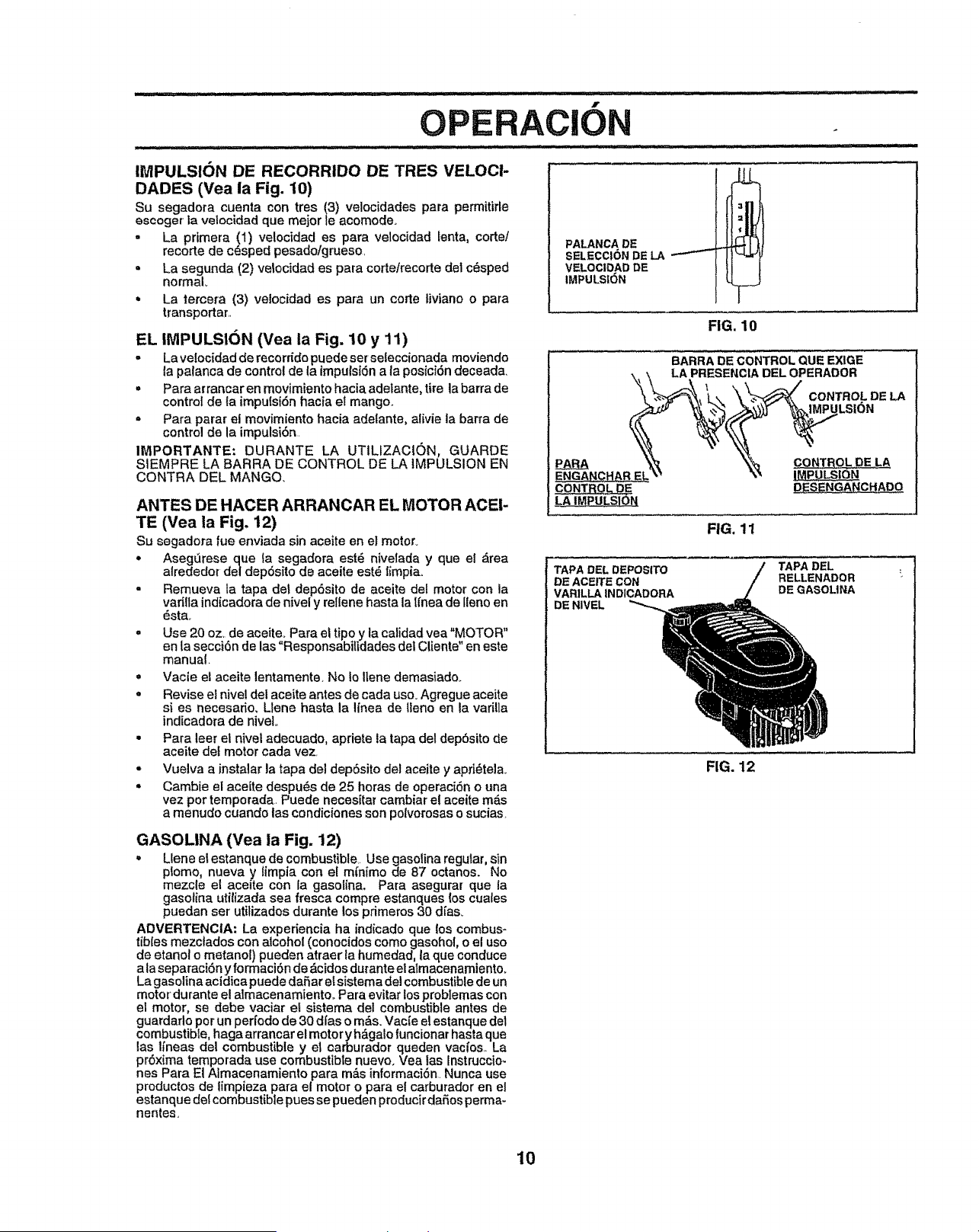
IMPULSION DE RECORRIDO DE TRES VELOCI-
DADES (Yea la Fig. 10)
Su segadora cuenta con tres (3) velocidades para perrnitirte
escoger la velocidad que mejor/e acomode_
- La primera (1) ve!ocidad es para velocidad lenta, corte!
recorte de c_sped pesadoigrueso,
= La segunda (2) vetocidad es para corte/recorte dei c_sped
normal
= La tercera (3) velocidad es para un corte liviano o para
transportar,,
EL IMPULSION (Vea la Fig. 10 y 11)
o La velocidad de recorridopuede set seleccionada moviendo
la palanca de control de la impulsiSn a la posici6n deceada,
,, Para arrancar en mevimiento hacia adetante, tire la barra de
control de la impulsidn hacia el mango,
° Para parar el movimiento hacia adelante, alivie la barra de
control de la impulsi6n,
IMPORTANTE: DURANTE LA UTILIZACI(_N, GUARDE
SIEMPRE LA BARRA DE CONTROL DE LA iMPULSION EN
CONTRA DEL MANGO.
ANTES DE HACER ARRANCAR EL MOTOR ACEI-
TE (Vea la Fig. 12)
Su segadora rue enviada sin aceite en el motor.
• Asegtlrese que la segadora est_ nivetada y que el drea
alrededor del dep6sito de aceite est_ limpia.,
. Remueva la tapa det depdsito de aceite del motor con la
varilla indicadora de nivel y rellene hasta la tfnea de lleno en
dsta,,
= Use 20 oz, de aceiteo Para el tipo y la calidad vea "MOTOR"
en la secci6n de las "Responsabitidades del Cliente" en este
manual.
= Vacie el aceite lentamente, No Io Ilene demasiado,.
o Revise el nivel del aceite antes de cada uso. Agregue aceite
si es necesado. Llene hasta la linea de lleno en la varilla
indicadora de nivel.
• Para leer el nivel adecuado, apriete ta tapa del depbsito de
aceite det motor cada vez
° Vuelva a instalar la tapa del depSsito del aceite y apri_tela<.
° Cambie el aceite despu_s de 25 horas de operaci6n o una
vez pot temporada, Puede necesitar cambiar el aceite m_s
a menudo cuando las condiciones son polvorosas o sucias
F
OPERACION
PALANCA DE
SELECCI(3N DE LA i
VELOCIDAD DE
IMPULSION
FIG. 10
BARRA DECONTROL QUE EXIGE
,< \ LA PRESENCIADEL OPERADOR
"%\ J._pU._LS|ON
CONT__ _SENGANCHADO
FIG. 11
TAPA DEL
RELLENADOR :"
DE GASOLINA
TAPA DEL DEPOSITO
DE ACEtTE CON
VARILLA INDICADORA
DE NIVEL
FIG. 12
GASOLINA (Yea la Fig. 12)
. Llene el estanque de combustible Use gasolina regular, sin
ptomo, nueva y ltmpia con el mfnimo de 87 octanos. No
mezcle el aceite con ia gasolina. Para asegurar que la
gasofina utitizada sea fresca compre estanques (os cuates
puedan ser utilizados duranle los primeros 30 dfas_
ADVERTENCIA: La experiencia ha indicado que los combus-
tibles mezciados con alcohol (conocidos como gasohol, o el uso
de etanol o metanol) pueden atraer ta humedad, la que conduce
a laseparaci6n y formaci6n do dcidos durante el almacenamiento,
La gasolina acidica puede dafiar e{sistema del combustible de un
motor durante e! almacenamiento,, Para evitar losproblemas con
el motor, se debe vaciar el sistema del combustible antes de
guardarlo por un periodo de 30 dfas o m_,s.Vacfe el estanque det
combustible, haga arrancar el motor y hdgalofuncionar hasta que
las l/neas de| combustible y et carburador queden vacfos,, La
pr6xima temporada use combustible nuevo° Vea las Instruccio-
nes Para El Almacenamiento para m&s informaci6n Nunca use
productos de limpieza para el motor o para e! earburador en el
estanque de!combustible pues se pueden producir dafios perma-
nenles,
10
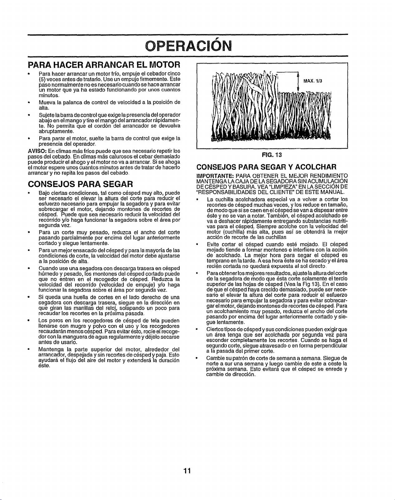
PARA HACER ARRANCAR EL MOTOR
* Para hacer arrancar un motor frfo, empuje el cebador cinco
(5) veces antes de tratarlooUse un empuje firmemente_ Este
paso norma{mente no es necesafio cuando se hace arrancar
un motor que ya ha estado funcionando per unos cuantos
minutes,,
* Mueva la palanca de control de vefocidad a la posici6n de
alla.
* Sujete la barra de control 9ue exige la presencia del operador
abajo en el mango ytire el mango del arrancador r_ipidamen-
re., NO permita que el cordSn del arrancador se devuelva
abruptamente.
o Para parar el motor, suelte ta barra de control que exige la
presencia del operader,
AVISO: En climas m&s frfes puede que sea necesado repetir los
pasos del cebado, En climas mrs calurosos el cebar demasiado
puede producir el ahogo y el motor no va a arrancar,, Si se ahoga
el motor espere unos cuantos minutes antes de tratar de hacerlo
arrancar y no repita los pasos del cebado.
CONSEJOS PARA SEGAR
. Bajo ciertas condiciones, tat come c_sped muy alto, puede
ser necesario et elevar la altura del corte para reducir el
esfuerzo necesario para empujar la segadora y para evitar
sobrecargar el motor, dejando montones de recortes de
c6sped. Puede que sea necesario reducir la velocidad del
recorridoy/o haga funcionar la segadora sobre et &tea per
segunda vez,
= Para un corte muy pesado, reduzca el ancho del corte
pasando parcialmente per encima del lugar anteriormente
cortado y siegue ]entamente,.
• Para un mejor ensacado del c_sped y para la mayoria de las
condiciones de code, la velocidad del motor debe ajustarse
a la posici6n de alia.
° Cuando use una segadora con descarga trasera en cdsped
ht_medo y pesado, los montones def c_sped cortado puede
que no entrenen el recogeder de c_sped. Reduzca la
velocidad del recerrido (velocidad de empuje) y/o haga
funcionar la segadora sobre el &tea per segunda vez.,
- Si queda una huelfa de codes en el lade derecho de una
segadora con descarga trasera, siegue en la direcci6n en
que giran las manillas del retoj, solapando un poco para
recaudar los recortes en la pr6xima pasada.
• Los pores en les recogedores de c_sped de tela pueden
lienarse ten mugre y pelvo con el use y los recogedores
recaudar_n menos cesped. Para evitar _sto, rocfe et recoge-
dorcon la manguera de agua regularmente y ddjelo secarse
antes de usarle.
° Mantenga la parte superior del motor, alrededor del
arrancador, despejada y sin recortes de c_sped y paja,, Esto
ayudar_ el flujo del aire del motor y extender_l la duraci6n
_sle°
MAX_ 1/3
FIG. 13
CONSEJOS PARA SEGAR Y ACOLCHAR
IMPORTANTE: PARA OBTENER EL MEJOR RENDIMIENT O
MANT.ENGA LA CAJA DE LA SEGADORA SIN ACUMUL_CION
DE CESPED Y BASURA. VEA =LIMPIEZA" EN LA SECCION DE
"RESPONSABILIDADES DEL CLtENTE" DE ESTE MANUAL,
• La cuchiUa acolchadora especial va a volver a cortar los
recortes de cdsped muchas veces, y los reduce en tamarto,
de mode quesi se caen en el c_sped se van a dispesar entre
6sle y no se van a notaro Tambien, el c_sped acoichado se
va a deshacer r&pidamente entregando substancias nutriti-
vas para et cdsped. Siempre acolche con la velocidad del
motor (cuchilla) mds alia, pues as{ se obtendrd la meier
acci6n de recorte de las cuchillas
• Evite cortar el c_sped cuando est_ mojado, El c6sped
mojado tiende a formar montenes e inteffiere con la acci6n
de acolchado, La mejor hera para segar el c_sped es
temprano en la tarde_A esa hera 6ste se ha secado y et _rea
recidn cortada no quedard expuesta al sol directo
• Para obtener los mejores resuttados, ajListe la altura del corte
de la segadora de mode que dsta corte solamente el tercio
superior de las hojas de c_sped (Vea la Fig 13). En el case
de que el c_sped haya crecido demasiado, puede ser nece-
sario el elevar {a altura del corte para reducir el esfuerzo
necesario para empujar la segadora y para evitar sobrecar-
gar el motor, dejando montones de recortes de c6sped° Para
un acolchamiento muy pesado, reduzca el ancho del code
pasando per encima del lugar antedormente cortado y sie-
gue lentamente,
. Ciertos tipos de c_sped y sus condiciones pueden exigir que
un drea tenga que ser acolchada per segunda vez para
esconder completamente los recortes, Cuando se haga el
segundo code, siegue atravesado o en forma perpendicular
a la pasada det primer corteo
• Cambie su patr6n de code do semana a semana,, Siegue de
node a sur una semana y lue_o cambie de este a oeste la
pr6xima semana. EsIo evitara que el c_sped se enrede y
cambie de direcci6n_
11
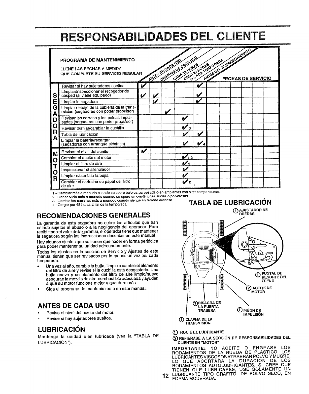
E
G
A
g
Revisar et nlvel det aceite
Cambiar el a'ce'i'tedei motor
_ ump_areii,trodeaire
T I_. nar ehsilenclador
Umpiar olcambiar ]a bujfa
a Cambtar el cartuch0 de papet del f'iliio......
de aire
Revisar st hay sujetadores sueftos ...... ._# ..........
Limptarllnspeccionar el recogedor de
c_sped (si vIene equipado) _' _#'
Limpiarla segadora 1t_ I_ ............
Umpiar debajo de la cublerta de la trans-
mim6n (segaderas con poder propulsor)
Revisarlas correas y las poleas lmpuF '_ I .....[.........
sadas (segadoras con poder propulsor) v .. [..................... [
abia ,,,br, ................i v' i 1 ............................I !
Umptar la bateria!recargar
(segaderas con arranque el_ctrica) .................._: ,,t_ ,,. 1_4
t,1"I,2
_,##w2 .........
1 - Camb]ar rods a menudo cuando se opera baJo carga pesada o en amb[entes con attas temperaturas,
2 _ Dar servlcio m;_s a menudo cuando se opere en condfctones suctas o polvorosas.
3 - Camble las cuchitlas m&s a menudo cuando stegue en terteno arenoso
4 - Cargar par 48 betas a! fir} de la temporada,
RECOMENDACIONES GENERALES
La garantia de esta segadora no cubre los artfculos que han
estado sujetos al abuse o a ta negiigencia del operador. Para
reeibir todo el vatorde la garantfa el operador tiene que mantener
Ia segadora segOn las instrucciones descritas en este manual.
Hay algunos ajustes que se tienen que haeer en farina peri6dica
para poder mantener su unidad adecuadamenteo
Todos los ajustes en la secci6n de Servicio y Ajustes de este
manual tienen que ser revisados per Io menos un vez par cada
temporada.
• Una vez al aSo, carnbie la bujfa, limpie o cambie el elemento
del fiitro de aire y revise si la cuchilla est&desgastada. Una
bujia nueva y un elemento del filtro de aire limpio/nuevo
aseguran la mezcla de aire-combustibleadecuada y ayudan
a que su motor funcione mejor y que dure re&s,.
• Siga el programa de mantenimiento en este manual
TABLA DE LUBRICACI(3N
(_) AJUSTADOR DE
RUEDAS
(_PUNTALDE
RESORTEDEL
FRENO
ANTES DE CADA usa
,, Revise el nivel del aceite del motor
- Revise si hay sujetadores sueltos..
LUBRIOACION
Mantenga la unidad bien lubricada (vea fa "TABLA DE
LUBRICACI6N")._
12
BISAGRADE
PUERTA
TRASERA
(_)CLAVIJA DE LA
TRANSMISION
O PII_ON DE
IMPULSION
(_ ROCIEELLUBR[CANTE
(_) REFIERASE A LA SECCI6N DE RESPONSAB1LIDADESDEL
CLIENTEEN "MOTOR"
IMPORTANTE: NO ACEITE O ENGRASE LOS
RODAMIENTOS DE LA RUEDA DE PLASTICO. LOS
LUBRICANTES VISCOSOS ATRAERAN POLVO Y MUGRE,
LO QUE ACORTARA LA DURACION DE LOS
RODAMIENTOS AUTOLUBRICANTES.. SI CREE QUE
TIENEN QUE LUBRICARSE, USE SOLAMENTE UN
LUBRICANTE TIPO GRAFITO, DE POLVO SECO, EN
FORMA MODERADA..
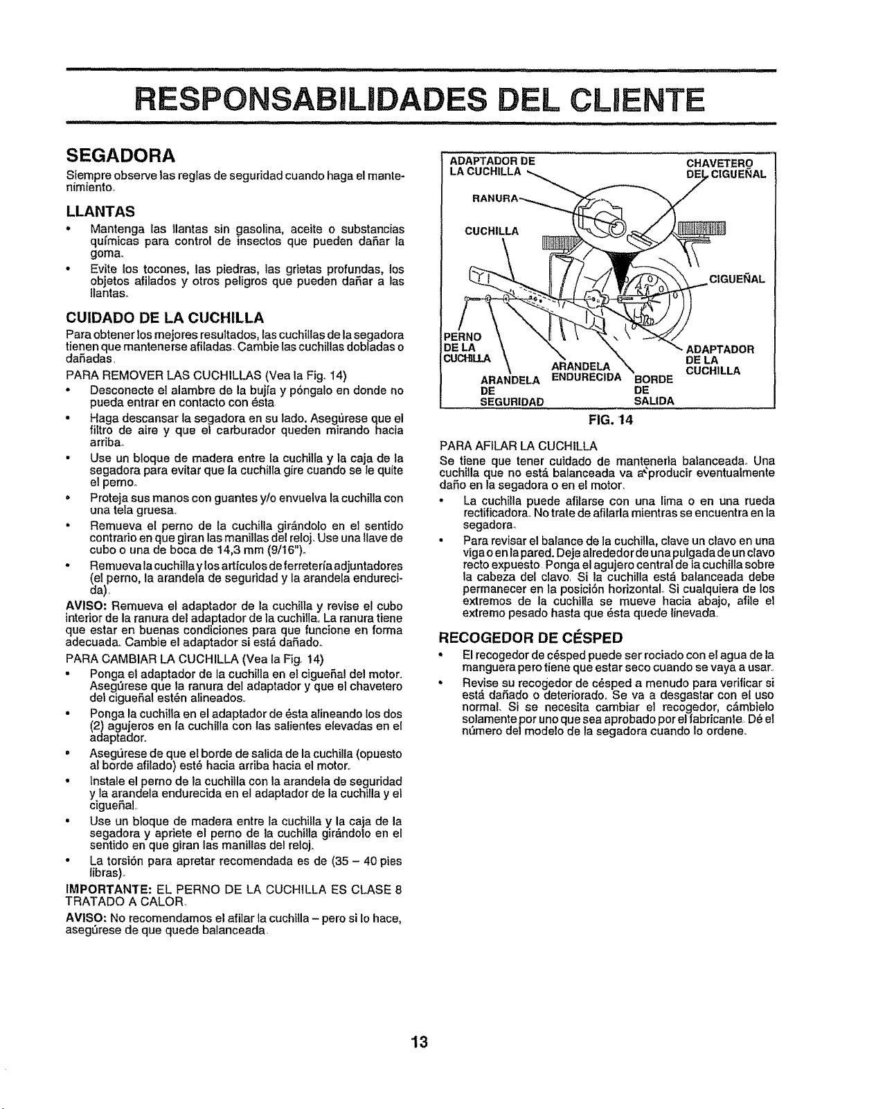
P LIDAD
SEGADORA
Siempre observe las reglas de seguridad cuando haga el mante-
nimiento
LLANTAS
o Mantenga |as _lantas sin _lasolina, ace|re o substancias
qufmicas para control de msectos que pueden daSar la
goma.
• Evite ios tocones, las piedras, las gdetas profundas, los
objetos afilados y otros peligros que pueden daSar a tas
Ilantas_
CUIDADO DE LA CUCHILLA
Para obtener los mejores resultados, las cuchiliasde la segadora
tienen que mantenerse afiladas, Cambie |as cuchillasdobladas o
da_adas
PARA REMOVER LAS CUCHILLAS (Vea la Fig° 14)
• Desconecte el alambre de la bujfa y p6ngalo en donde no
pueda entrar en contacto con 6sta
• Haga descansar la segadora en su lado. Asegt_rese clue el
_tro de aire y que el carburador queden mirandohacia
arribao
• Use un bloque de madera entre la cuchilla y la caja de la
segadora para evitar que la cuchil{a gire cuando se le qu{te
el pemo.
• Proteja sus manos con guantes y/o envuelva la cuchilla con
una tela gruesa
• Remueva el perno de la cuchilla gir&ndo[o en el sentido
contrado en que giran las manilias del reloj. Use una llave de
cubo o una de boca de 14,3 mm (9/16)o
o Remueva Iacuchilla ylos art_culos de ferreterfa adjuntadores
(el perno, la arandela de seguridad y la arandela endureci-
da)
AVISO: Remueva el adaptador de la cuchiHa y revise el cubo
interior de la ranura del adaptador de la cuchilta La ranura tiene
que estar en buenas condiciones para que funcione en forma
adecuada Cambie el adaptador si est& dafiado.
PARA CAMBIAR LA CUCHILLA (Vea _a Fig 14)
• Ponga el adaptador de la cuchilla en el cigueSal del motor
Aseg_rese que ta ranura del adaptador y que el chavetero
det cigueSal est_n alineados
• Ponga la cuchilla en el adaptador de _sta atineando losdos
(2} agujeros en {a cuchflla con las salientes elevadas en el
adaptador.
" AsegL_rese de que e_borde de salida de la cuchilla (opuesto
al borde afilado) est_ hacia arriba hacia el motor
• lnstale el perno de la cuchiila con la arandela de seguridad
y la arandela endurecida en el adaptador de la cuchilla y el
cigueSaL
• Use un b|oque de madera entre ta cuchitla y la caja de la
segadora y apdete el perno de la cuchilta gir&ndolo en el
sentido en que giran las manilias del reloj.
• La torsiSn para apretar recomendada es de (35 - 40 pies
libras)o
tMPORTANTE: EL PERNO DE LA CUCH1LLA ES CLASE 8
TRATADO A CALOR
AVISO: No recomendamos el afilar la cuchitla - pero si 1ohace,
asegSrese de que quede balanceada
ADAPTADOR DE
LA CUCHILLA
CHAVETERO
DEI , C[GUENAL
CUCHILLA
ARANDELA
DE
SEGURtDAD
CIGUENAL
_ ADAPTADOR
A_RANDELA DE LA
CUCHILLA
ENDURECIDA BORDE
DE
SALIDA
FIG. 14
PARA AFILAR LA CUCHILLA
Se tiene que tener cuidado de mantenefla balanceadao Una
cuchilla que no est,, balanceada va a_producir eventualmente
dafio en la segadora o en el motor
° La cuchilla puede affiarse con una lima o en una rueda
rectificadora No trate de afilarla mientras se encuentra en Ea
segadora.
• Para revisar el barance de ia cuchilla, clave un ctavo en una
viga o en lapared. Deje alrededor de una pulgada de un clavo
recto expuesto Ponga el agujero central de fa cuchilla sobre
la cabeza del clavo Si la cuchiila est_ balanceada debe
permanecer en la posici6n horizontal° Si cualquiera de log
extremos de la cuchilla se mueve hacia abajo, afile el
extremo pesado hasta que _sta quede linevada
RECOGEDOR DE CESPED
* El recogedor de c_sped puede ser rociado con el agua de la
manguera pero tiene que estar seco cuando se vaya a usar
. Revise su recogedor de c_sped a menudo para verificar si
est& daSado o deterioradoo Se va a desgastar con el uso
normal. Si se necesita cambiar el recogedor, c&mbielo
so)amente por uno que sea aprobado pot el fabricante, D_ el
n_mero delmodelo de la segadora cuando Io ordene.
13
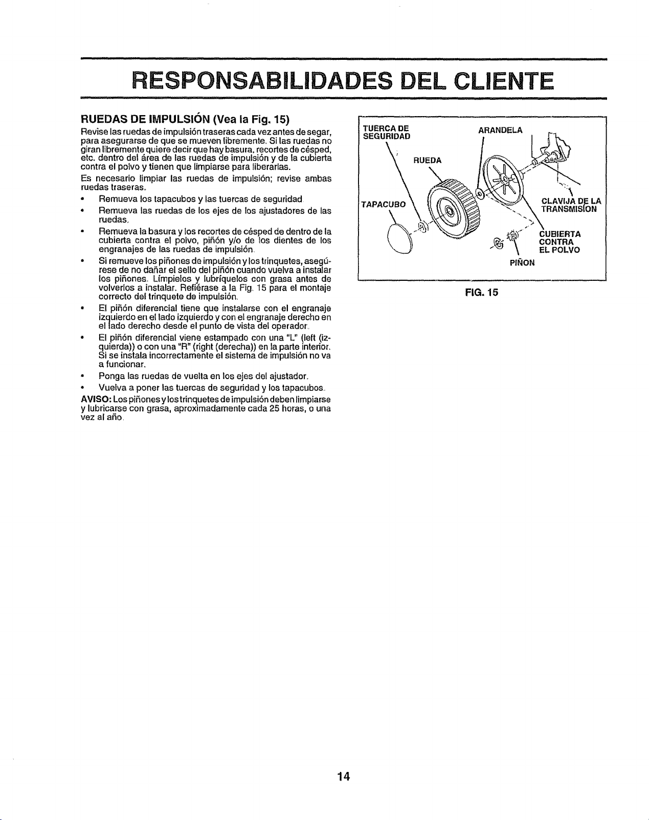
RUEDAS DE IMPULSION (Vea la Fig. 15)
Revise las ruedas de impulsi6n traseras cada vez antes de segar,
para asegurarse de que se mueven libremente_ Si las ruedas no
giran libremente quiere decir que hay basura, recortes de c_sped,
etc. dentro del _rea de las _uedas de impulsi6n y de la cubserta
contra el potvo y tienen que limpiarse para liberarlas.
Es necesario limpiar las ruedas de tmpulsi6n; revise ambas
ruedas traseras..
• Remueva los tapacubos y las tuercas de seguridad
• Remueva las ruedas de los ejes de los ajustadores de las
ruedas.
• Remueva la basura y los recortes de c_sped de dentro de la
cubierta centra e! polvo, pifi6n ylo de los dientes de los
engranajes de las ruedas de impulsi6n.
° Si remueve los pifiones de impulsi6n y los trinquetes, asegti-
rese de no dafiar el sello del pifi6n cuando vuelva a instatar
los pifiones_ Limpieles y lubriquelos con grasa antes de
volverlos a instalar. Refi_rase a la Fig. 15 para el montaje
correcto det trinquete de impufsi6n.
° E! pi55n diferencial tiene que instalarse con el engranaje
izquierdo en el lade izquierdo y con el engranaje derecho en
ellado derecho desde el punto de vista det operador..
• El pi56n diferencial viene estampado coi'] una "L" !left (iz-
quierda)) o con una "R" (right (derecha)) en la parte interior.
$i se instala incorrectamente el sistema de impulsi6n no va
a funcionar.
• Ponga las ruedas de vuella en los ejes det ajustador.
° Vuelva a poner las tuercas de seguridad y los tapacubos.
AMtSO: Lospifiones ylos trinquetes de impulsi6n deben limpiarse
y lubricarse con grasa, aproximadamente cada 25 horas, o una
vez al afio.
!TUERCA DE ARANDELA
SEGURIDAD
RUEDA
TAPACUBO
PINON
CLAVIJAD_LA
TRANSM[StON
CUBIERTA
CONTRA
EL POLVO
FIG. 15
14
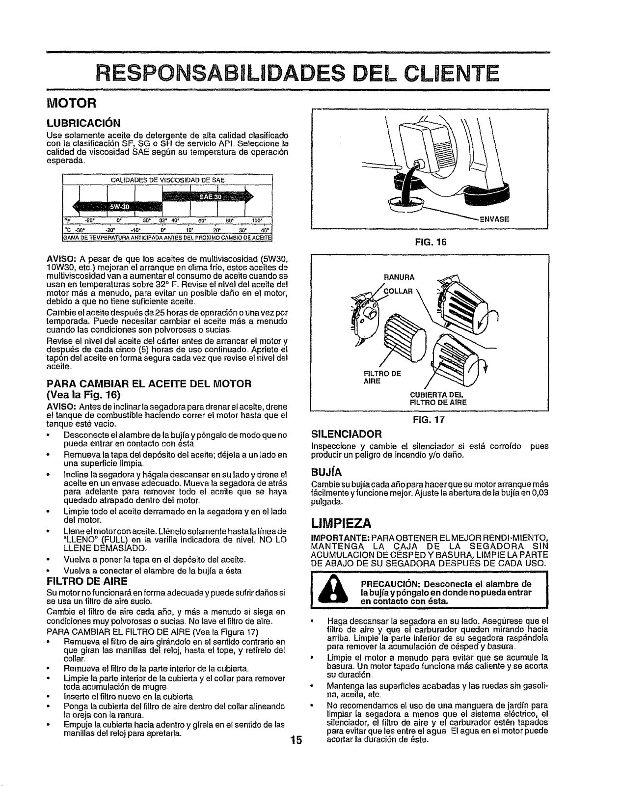
MOTOR
LUBRICAClON
PONSABILI D L CUENTE
Use solamente aceite de detergente de alta calidad clasificado
con la clasilicaci6n SF, SG o SH de servlclo API Seteccione la
calidad de viscosidad SAE seg6n su temperatura de operaci6n
esperada
CALIDADES DE VtSCOS1DAD DE SAE
1 .... -1
_F *20" O* 30 ° 32 w 40" 60 _ _g" t_"
_'C -30' -20" -10" 0" 10" _0" 30" 40"
3AMA DE TEMPERATURA ANTICIPADA ANTES DEL PROXIMO CAMBIO DE ACEITE
ENVASE
FIG. 16
AVISO: A pesar de que los aceites de multiviscosidad (5W30,
10W30, etc.) mejoran el arranque en clima frio, estos aceites de
multiviscosidad van a aumentar el consumo de aceite cuando se
usan en temperaturas sobre 32 ° E Revise el nivel del aceite del
motor m6s a menudo, para evitar un posible dafio en el motor,
debido a que no tiene suficiente aceite_
Cambie el aceite despu6s de 25 horas de operaci6n o una vez pot
temporada, Puede necesitar cambiar el aceite m_s a menudo
cuando las condiciones son polvorosas o sucias
Revise el nivel del aceite del c&rter antes de arrancar el motor y
despu6s de cada cinco (5) horas de uso continuado_ Apriete el
tap6n del aceite en forma segura cada vez que revise el nivel del
aceite.
PARA CAMBIAR EL ACEITE DEL MOTOR
(Vea la Fig. 16)
AVtSO: Antes de inclinar la se_adora para drenar el aceite, drene
el tanque de combustible haclendo cotter el motor hasta que el
tanque est6 vacio..
• Desconecte el alambre de la buiia y p6ngalo de modo que no
pueda entrar en contacto con esta
• Remueva la tapa del dep6sito del aceite; d6jela a un lado en
una supefficie limpia
° incline la segadora y h&gala descansar en su lado y drene el
aceite en un envase adecuado. Mueva la segadora de atrfis
para adelante para remover todo el aceite que se haya
quedado atrapado dentro del motor.
• Limpie todo el aceite derramado en fa segadora yen el lado
del motor.
• Llene el motor con aceite_ LI6nelo solamente basra la Ifnea de
=LLENO" (FULL) en la varilta indicadora de niveL NO LO
LLENE DEMASLADO.
° Vuelva a poner la tapa en el dep6sito del aceite..
° Vuelva a conectar et alambre de la bujfa a 6sta
FILTRO DE AIRE
su motor no funcionar& en forma adecuada y puede sufrir dafios si
se usa un fillro de afre sucioo
Cambie el flltro de aire cada afio, y m&s a menudo si siega en
condiciones muy polvorosaso sucias No lave el filtro de aire.
PARA CAMBIAR EL FILTRO DE AIRE (Vea la Figura 17)
. Remueva el fiitro de aire girfindolo en el sentido contrario en
que giran las manillas det reloj, hasta el tope, y retfrelo del
collar.
• Remueva el filtro de la parte interior de la cubierta.,
• Limpie la parte interiorde la cubierta y el collar para remover
toda acumutaei6n de mugre.
• Inserte e! filtro nuevo en la cubierta
• Ponga la cubierta del filtro de aire dentro de1collar alineando
la oreja con la ranura..
. Empuje la cubierta hacia adentro y girela en el sentido de las
manillas del reloj para apretarla.
RANURA
__\COLLAR _
F1LTRO DE
AIRE
CUBIERTA DEL
FILTRO DE A1RE
FIG. 17
SILENCIADOR
Inspeccione y cambie et silenciador si est_ corro_do pues
producirun peligro de incendio y/o daSo_
BUJiA
Cambie su bujia cada afio para hacer que su motor arranque m6s
f_cilmente y funcione mejor..Ajuste la abertura de la buji'a en 0,03
pulgada,
15
LIMPIEZA
IMPORTANTE: PARA OBTENER EL MEJOR RENDI-M|ENTO,
MANTENGA LA CAJA DE LA SEGADORA SIN
ACUMULACION DE CI_SPED Y BASURA.. LIMPIE LA PARTE
DE ABAJO DE SU SEGADORA DESPUES DE CADA USO.
I _ PR_CAL_CJON_ De'c°ne_te e| a|amb_te delen _enta_to =,,_r,_n ,€_
la buj_ay p6ngato en donde no pueda entrar
,,,,.. ....
• Haga descansar la segadora en su tado. Asegurese que el
_tro de aire y que el carburador queden mirandohacia
arriba Limpie la parte inferior de su segadora rasp&ndola
para remover la acumulaci6n de cdsped y basura,
° Limpie el motor a menudo para evitar que se acumule la
basura,. Un motor tapado funciona m&s catiente y se acorta
su duraci6n
• Mantenga las superficies acabadas y las ruedas sin gasoli-
ha, aceite, etc.
• No recomendamos el uso de una manguera de jardfn para
limpiar la segadora a menos que el sistema el6ctrico, el
sitenciador, el filtro de aire y el carburador est6n tapados
para evitar que les entre el agua El agua en el motor puede
acortar la duraci6n de 6ste.
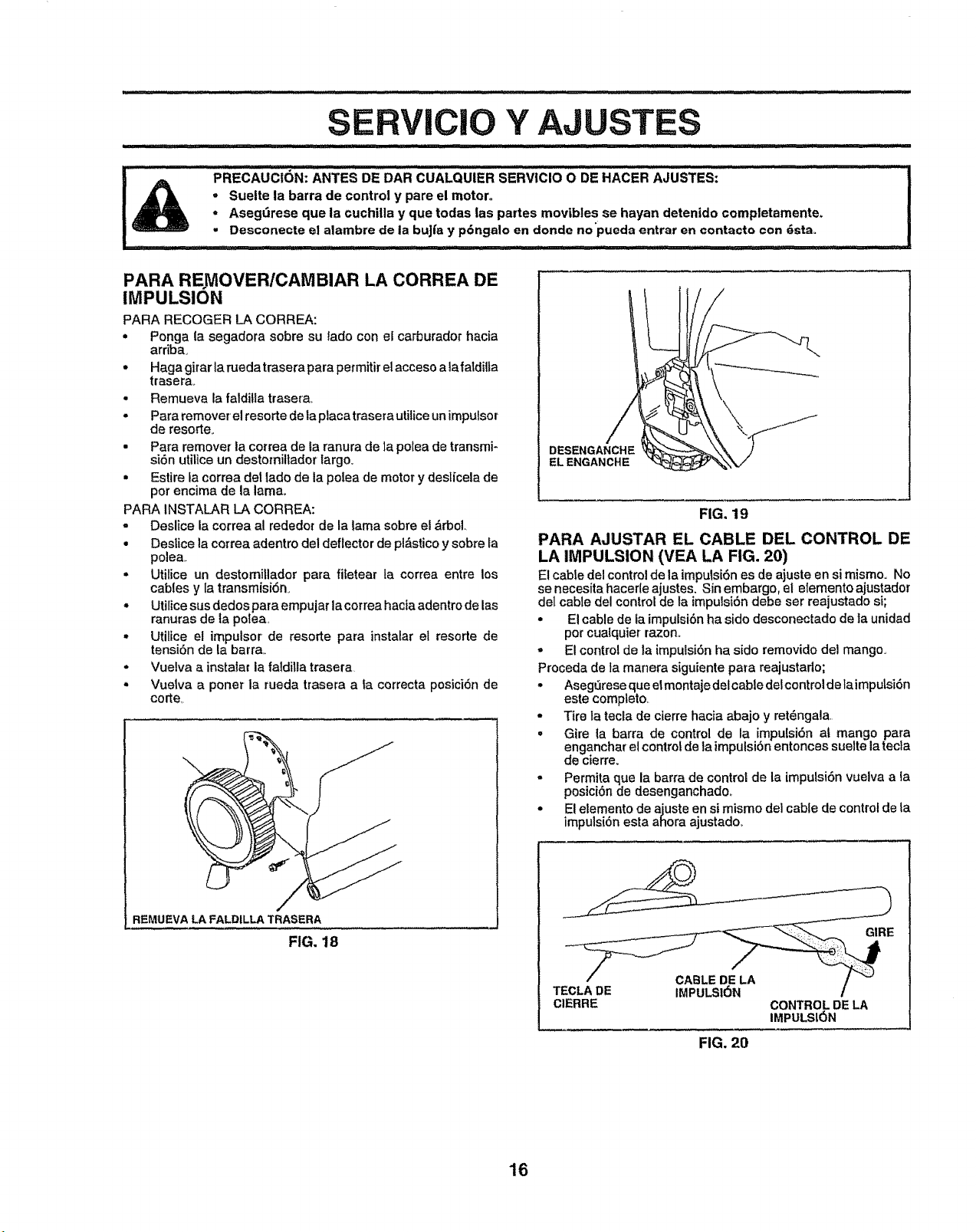
SERVICIO Y AJUSTES
PRECAUCiON: ANTES DE DAR CUALQUIER SERViCIO O DE HAcER AJUSTES:
• Suelte la barra de control y pare el motero
o Asegt_rese que ia cuchilla y que todas las partes mov|bles se hayan detenido completamente.
• Desconecte el alambre de la buJfay p6ngalo en deride no pueda entrar en contacto con gstao
................................ ii 'ltt ttllltltttt ..... '! ii,llttt IJtt .....
PARA RE MOVER/CAMBIAR LA CORREA DE
IMPULSION
PARA RECOGER LA CORREA:
° Ponga la segadora sobre su lade con el carburador hacia
arriba.
° Haga girar ta pJeda trasera para permitir el acceso a la fatdilta
trasera,_
• Remueva la falditla trasera.
• Para removerel resorte de la piaca trasera utilice un impulsor
de resorte.
• Para remover la correa de la ranura de la polea de transmi-
siSn utilice un destorniltador largo.
• Estire la correa del lade de la polea de motor y desl[cela de
per encima de la lama.
PARA INSTALAR LA CORREA:
= Deslice la correa al rededor de la lama sobre el ,_rbol,
° Deslice la correa adentro del deflector de pl_stico y sobre la
polea,,
• Utilice un destomillador para fitetear la correa entre los
cables y la transmisi6n_
• Utilice sus dedos para empujar la correa hacia adentro de las
ranuras de ta polea,
- Utitice el impulsor de resorte para instalar el resorte de
tensi6n de la barra,,
° Vuelva a instaiar la faldilla trasera
• Vuetva a porter la rueda trasera a ta correcta posici6n de
corte,,
REMUEVA LA FALDILLA TRASERA
FIG, 18
DESENGANCHE
ELENGANCHE
FIG. 19
PARA AJUSTAR EL CABLE DEL CONTROL DE
LA IMPULSION (VEA LA FIG. 20)
El cable del controlde la impulsi6nes de ajuste en si mismo° No
se necesita hacerle ajustes, Sin embargo, el elemento ajustador
del cable del control de la impulsi6n debe ser reajustado si;
• El cable de Jaimpulsi6nha side desconectado de la unidad
par cualquier razon,
- El control de la impulsi6n ha side removido del mango,
F3roceda de la manera siguiente para reajustado;
• AsegOrese que elmontaje delcabfe delcontroldelaimputsi6n
este complete.
- Tire la tecia de cierre hacia abajo y ret_ngala.
° Gire la barra de control de la impu[si6n at mango para
enganchar el contro_ de la impulsibn entonces suelte ta tecla
de cierre.
- Permita que la barra de control de la imputsi6n vuelva a ta
posiciSn de desenganchadoo
° El eiemento de ajuste en si mismo del cable de control de la
impuisi6n esta ahora ajustado.
TECLA DE IMPULSI6N
CIERRE
CONTROL DE LA
IMPULSL_)N
FIG. 20
16
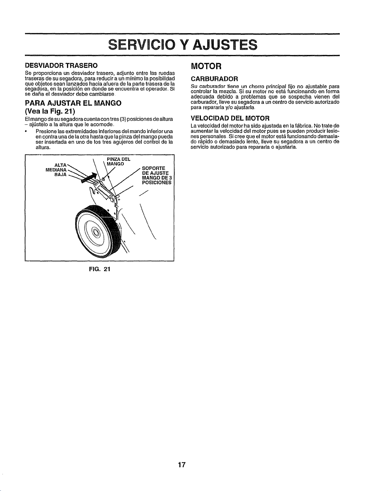
iu ,i, ,ll,i .... ,lllllii ............... _,,
Y AJUSTES
,lllll ,ll,i,,i,i ii ,111 i i,_1/ i
DESVIADOR TRASERO
Se proporciona un desviador trasero, adjunto entre las nJedas
traseras de su segadora, para reducir a un m{nimo la posibilidad
que objetos sean lanzados hacia afuera de la parte trasera de la
segaaora, en la posiei6n en donde se encuentra el operador.,Si
se daRa el desviador debe cambiarse.
PARA AJUSTAR EL MANGO
(Vea la Fig. 21)
Elman go de su segadora cuenta con tres (3) posiciones de affura
- aj_3steloa }a altura que le acomode.,
- Presione Zasextremidades inferiores del mando inferior una
en contra una de la otra hasta que la pinza del mango pueda
set insertada en uno de los tres agujeros del control de la
aiturao
MOTOR
CARBURADOR
Su carburador tiene un chorro principal fijo no ajustabJe para
controlar la mezcla. Si su motor no est,. funcionando en forma
adecuada debido a problemas que se sospecha vienen del
carburador, lleve su segadora a un centro de servicio autorizado
para repararla y/o ajustarla,
VELOCIDAD DEL MOTOR
La velocidad del motor ha sido ajustada en la f&bricao No irate de
aumentar la velocidad del motor pues se pueden producir lesio-
nes personales. Si cree que el motor est& funcionando demasia-
do r_pido o demasiado lento, I[eve su segadora a un centro de
servicio autorizado para repararla o ajustadao
PINZA DFL
ALT/ MANGO
MEDIANA _ SOPORTE
DE AJUSTE
BAJA MANGO DE 3
POSIClONES
FIG, 21
17
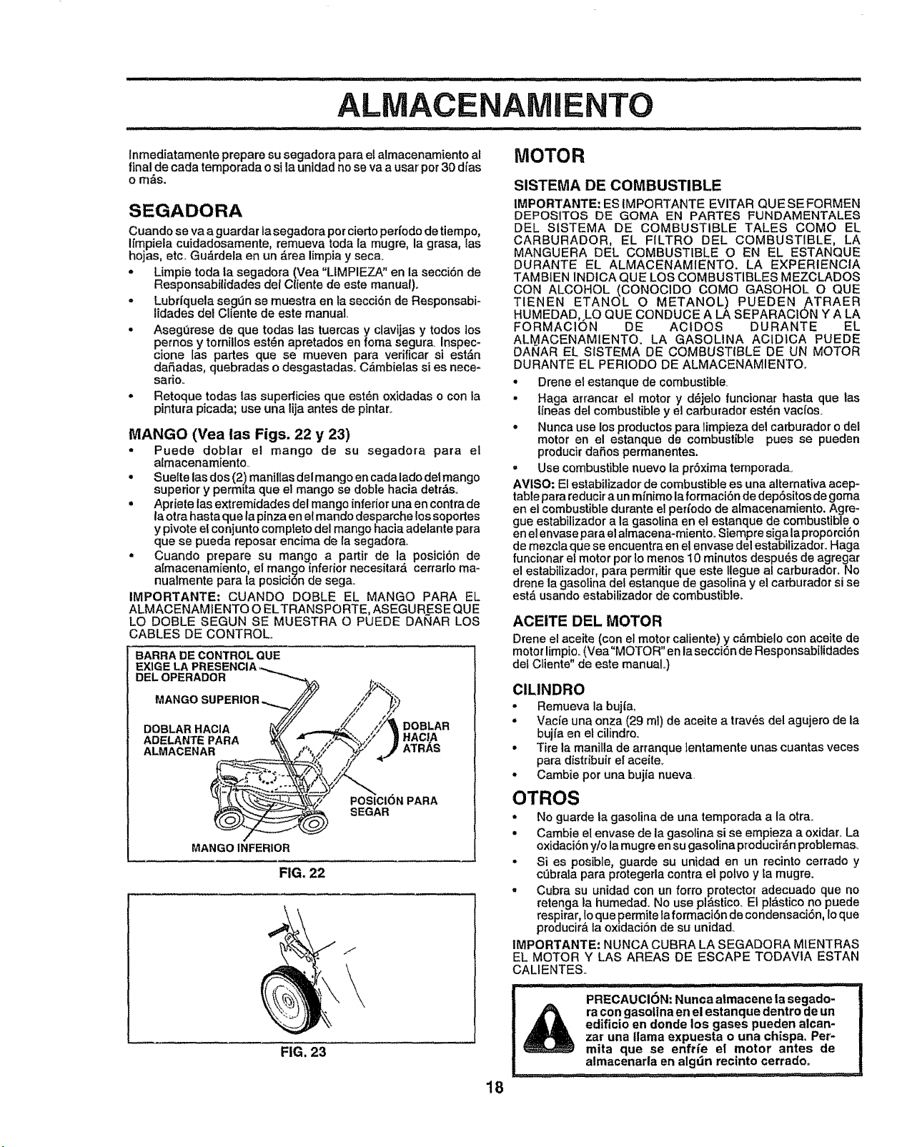
lnmediatamente prepare su segadora para et almacenamiento al
final de cada temporada o si la unidad no se va a usar per 30 dfas
o m_s.
SEGADORA
Cuando se va a guardar la segadora per cierto pert'odede tiempo,
Ilmpiela cuidadosamente, remueva toda la mugre, la grasa, las
hojas, etc. Gu_rdela en un _.rea limpia y seca.
o Limpie toda la segadora (Vea "LIMPIEZA" en la secci6n de
Responsabilidades del Cliente de este manual)°
• Lubrl'quela segdn se muestra en la secci6n de Responsabi-
lidades del Cliente de este manual
• AsegOrese de que todas las tuercas y clavijas y todos los
pernos y tornillos est_n apretados en foma segura Inspec-
clone las partes que se mueven para verificar si est&n
da_adas, quebradas o desgastadaso C_mbielas si es nece-
sarlo..
• Retoque todas las superficies que est6n oxidadas o con la
pintura picada; use una lija antes de pintar..
MANGO (Yea las Figs. 22 y 23)
* Puede doblar el mango de su segadora para el
almacenamiento..
, Suelte lasdos (2) maniflas del mango en cada lado detmango
superior y permita que el mango se doble hacia detrbs.
, Apriete las extremidades del mango inferior unaen contra de
laotra hasta que la pinza en el mando desparche los soportes
y pivote el conjunto complete del mango hacia adelante para
que se pueda reposar encima de la segadorao
o Cuando prepare su mango a partir de la posici6n de
a[macenamiento, el man_o inferior necesitar_, cerrarlo ma-
nualmente para la posicion de sega,.
IMPORTANTE: CUANDO DOBLE EL MANGO PARA EL
ALMACENAMIENTO O ELTRANSPORTE, ASEGURESE QUE
LO DOBLE SEGUN SE MUESTRA O PUEDE DANAR LOS
CABLES DE CONTROL°
BARRA DE CONTROL QUE
DOBLAR
/ ATRAS
,y, *"
POSICIONPARA
SEGAR
MANGO INFERIOR
FIG. 22
_J
FIG. 23
18
MOTOR
SISTEMA DE COMBUSTIBLE
IMPORTANTE: ES IMPORTANTE EVITAR QU E SE FORMEN
DEPOSITOS DE COMA EN PARTES FUNDAMENTALE8
DEL SfSTEMA DE COMBUSTIBLE TALES COMO EL
CARBURADOR, EL FILTRO DEL COMBUSTIBLE, LA
MANGUERA DEL COMBUSTIBLE O EN EL ESTANQUE
DURANTE EL ALMACENAMIENTO, LA EXPERIENCIA
TAMBIEN INDICA QUE LOS COMBUSTIBLES MEZCLADOS
CON ALCOHOL (CONOClDO COMO GASOHOL O QUE
TIENEN ETANOL O METANOL) PUEDEN ATRAER
HUMEDAD, LO QUE CONDUCE A LA SEPARACION Y A LA
FORMACIC)N DE ACtDOS DURANTE EL
ALMACENAMIENTO. LA GASOLINA ACID1CA PUEDE
DANAR EL SfSTEMA DE COMBUSTIBLE DE UN MOTOR
DURANTE EL PERIODO DE ALMACENAMIENTO.
• Drene el estanque de combustible.
• Haga arrancar el motor y d_jelo funcionar hasta que las
lfneas del combustible y el carburador est_n vacfos.
• Nunca use los productos para limpieza del carburador o del
motor en el estanque de combustible pues se pueden
producir dafios permanentes.
• Use combustible nuevo la pr6xima temporada.
AVISO: El estabilizador de combustible es una altemativa acep-
table para reducira un mfnimo laformaci6n de dep6sitos de goma
en el combustible durante el per/ode de almacenamiento, Agre-
gue estabilizador a la gasolina en el estanque de combustible o
en el envase para el almacena-miento. Siempre siga laproporci6n
de mezcla que se encuentra en el envase del estabilizador. Haga
funcionar el motor per Io menos 10 minutes despu_s de agregar
el estabilizador para permitir que este Ilegue a/carburador. No
drene la gasolina del estanque de gasolina y el carburador si se
est& usando estabilizador de combustible.
ACEITE DEL MOTOR
Drene el aceite (con el motor caliente) y c_mbielo con aceite de
motor limpio., (Vea"MOTOR" en la secci6n de Responsabilidades
def Cliente" de este manual°)
ClLINDRO
* Remueva la bujfa,
° Vacie una onza (29 ml) de aceite a trav_s del agujero de ta
bujta en et cilindro.
, Tire la manilla de arranque lentamente unas cuantas veces
para distribuir el aceite_
, Cambie per una bujta nueva
OTROS
= No guarde ta gasolina de una temporada a la otra_
• Cambie el envase de la gasolina si se empieza a oxidar. La
oxidaci6n yto la mugre en su gasolina producir_n problemas_
° Si es posibleo guarde su unidad en un recinto cerrado y
c_brala para protegerla contra el polvo y la mugre.
• Cubra su unidad con un forte protector adecuado que no
retenga Ia humedad. No use pl_stico. El pl_stico no puede
respirar, Io que permite la formaci6n de condensaci6n, Io que
producir_, la oxldaci6n de su unidad,
IMPORTANTE: NUNCA CUBRA LA SEGADORA MIENTRAS
EL MOTOR Y LAS AREAS DE ESCAPE TODAVIA ESTAN
CALIENTESo
L IIIIII JJl .... II JLII[ I .................. :
J PRECAUCI6N: Nunca atmacene la segado-
ra con gasolina en el estanque dentro de un
edificio en donde los gases pueden alcan-
zar una llama expuesta o una chispa. Per-
mita que se enfrfe el motor antes de
almacenarla en algdn recinto cerradoo
......, _,i, . ,i - ......_.... ,,,, '," ,,,
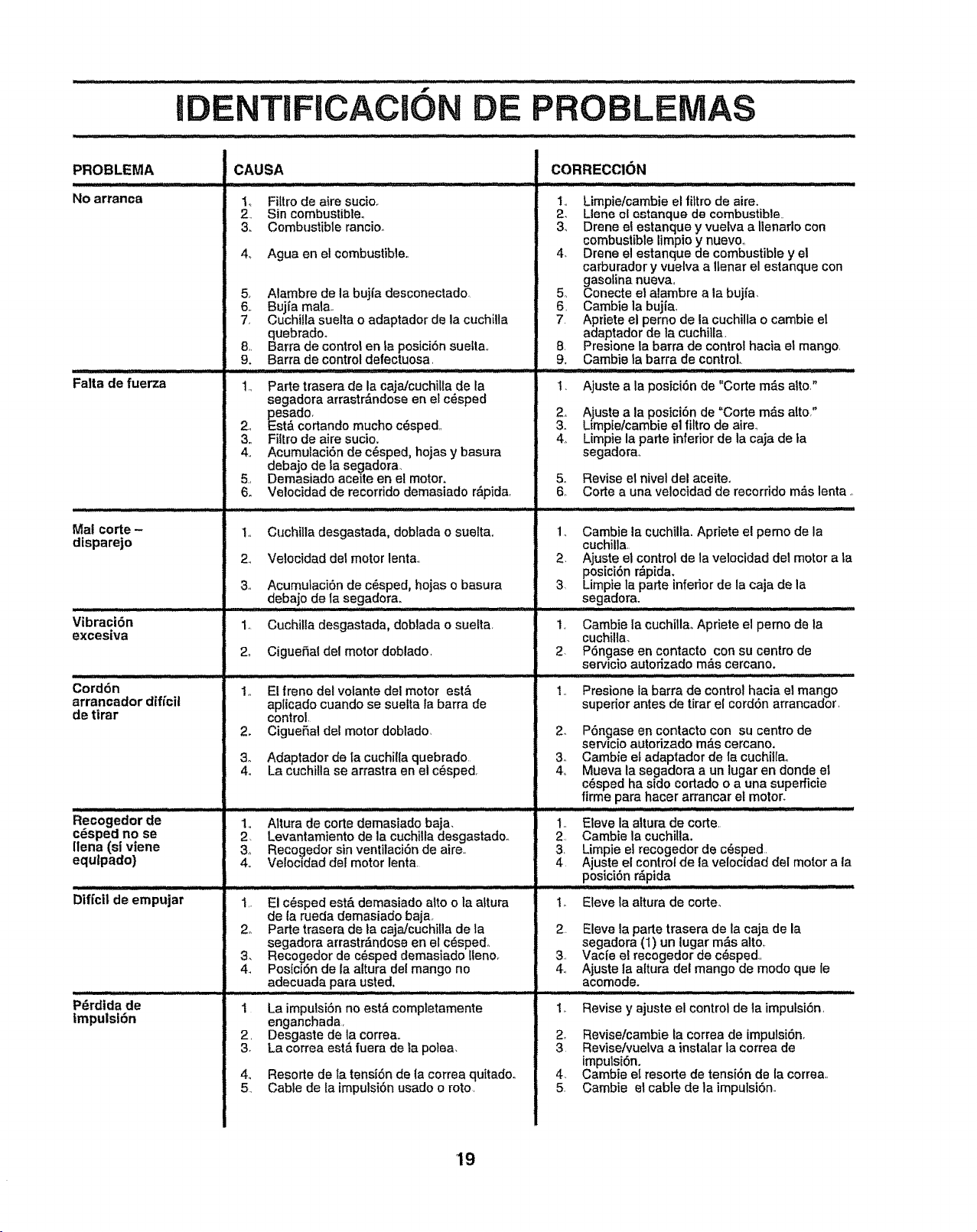
f
IDENTIFICACION E PROBLENIAS
PROBLEMA
No arranca
Falta de fuerza
Mal corte-
disparejo
Vibraci6n
exces|va
Cord6n
arrancador dff_cil
de tirar
Recogedorde
cdsped no se
Ilena(slviene
equlpado)
Dif[c|l de empujar
p rdidade
|mpuistbn
CAUSA
..................................... ....... ii i,_ _,N,,, llll
t,, Filtro de aire sucio,
2, Sin combustible,
3. Combustible rancio,
4., Agua en el combustible.,
6o
5, Alambre de la bujfa desconectado
_.. Bujfa mala,,
, Cuchilla suelta o adaptador de la cuchilla
quebradoo
8. Barra de control en ta posici6n suelta.,
9. Barra de control defectuosa,
1., Parte trasera de la caja/cuchilla de la
segadora arrastr_.ndose en el c6sped
p_esado,
2,, Estd cortando muchocdsped,
3., Filtro de aire sucio.
4,, AcumulaciSn de c_sped, hojas y basura
debajo de ta segadora,
Demasiado aceite en el motor,
Velocidad de recorrido demasiado rdpida.
1+, Ct+chilla desgastada, dobtada o suettao
2+, Velocidad det motor lenta.,
3+ AcumulaciSn de c+sped, hojas o basura
.....debajo de la
1,. Cuchilla desgastada, doblada o suetta,
2+ CigueSal del motor doblado,
1,, El freno dei volante del motor est_
ap[icado cuando se sueita ta barra de
control.
2, CigueSaidel motor dobtado,
3+, Adaptador de ta cuchilla quebrado
4o La cuchilla se arrastra en el c+sped,
1,, Altura de corte demasiado baja,
2. Levantamiento de la cuchilla desgastadoo
3_, Recogedor sin ventilaci+n de aire+,
4.. Velocidad del motor lenta+
1,. El c+sped est& demasiado alto o la a+tura
de ia rueda demasiado baja
2o Parte trasera de la cajalcuchilia de ta
segadora arrastr&ndose en el c+spedo
3, Reco_edor de c+sped demasiado !leno+
4_ Posicl6n de la altura del mango no
adecuada para usted.
_......._........................ i,ii iiii N .
1 La impulsiSn no est& completamente
enganchada+
2, Desgaste de ta correa,,
3, La correa est&fuera de +apolea,
4,, Resorte de ta tensiSn de la correa quitado+
5 Cable de ta impulsi6n usado o rote,
CORRECCION
1,, Limpie/cambie el _tro de aire+
2_ Llene el o,,tanque de combustible+
3, Drene el estanque y vuelva a Ilenado con
combustiblelimpio y nuevo_
4_ Drene el estanque de combustible y el
carburador y vuelva a Ilenar el estanque con
gasolina nueva,,
5, Conecte el alambre a ia bujia,
6, Cambie la bujia,
7 Apriete el perno de la cuchilla o cambie el
adaptador de la cuchitla,
8, Presione la barra de control hacia el mango,
9. Cambie ta barra de control,,
1. Ajuste a la posici6n de "Corte m&s alto."
, Ajuste a la posici6n de "Corte m&s alto,"
o Limpie/cambie el filtrode aim,,
4_ Limpie la parle inferior de ia caja de la
segadorao
5,, Revise el nivel del aceiteo
6, Corte a una velocidad de recorrido mils lenta.
2.
3
2_
Cambie la cuchilia. Apriete el pemo de la
cuchilla.
Ajuste el control de la velocidad det motor a |a
posici6n r&pida.
Limpte la parle inferior de la caja de la
segad°r.a- ....... . .....
Cambie la cuchilla_ Apriete el pemo de la
cuchilla,
PSngase en contacto con su centre de
servicio autofizado m&s cercano.
Presione la barra de control hacia el mango
superior antes de tirar el cordSn arrancador,
2, Pdngase en contacto con su centre de
servicio autorizado mds cercano.
3o Cambie el adaptador de la cuchilfao
4, Mueva la segadora a un lugar en deride el
c6sped ha side cortado o a una superficie
firme para hacer arrancar el motor.
1,, Eleve la altura de corte.
2, Cambie la cuchilla.
3, Limpie el recogedor de c6sped,
4, Ajuste el control de la velocidad del motor a la
:<os:c[5,,n,,,r&Pida ........ ....................
1_ Elevela attura de corte_
2. Eleve la parle trasera de la caja de la
segadora (1) un lugar m&s alto,
3, Vacfe el recogedor de c_sped,
4., Ajuste la altura del mango de mode que le
acomode,
/i Hl_ll, l lll ......
1_ Revise y ajuste el control de la impulsi6n,
2_ Revise/camb[e la correa de impuisi6n,
3. Revise/vuelva a instatar la correa de
impulsi6n,
4, Cambie ei resorte de tensi6n de la correa,,
5. Cambie el cable de la impulsi6n,.
19
D
MANUAL
L DUENO
MODELO NO.
917.377331
SI NECESITA
SERVICIO O PARTES
DE REPUESTO:
PARA SERVIC|O, LLAME ESTE
NOMERO DE TELI_FONO SIN
COBRO:
1-800-686-5811
(LA OPERADORA HABLA ESPAI_OL)
PARA PARTES DE REPUESTO,
INFORMACION Y PARA
ORDENAR, LLAMEESTE
NUMERO DE TELEFONO SIN
COBRO:
1-800-FON-PART
(1-800-366-7278)
£RRF'rIMnN ®
SEGADORA ROTATOR|A
6.25 CABALLOS DE FUERZA
DESCARGA TRASERA 22"
PODER PROPULSOR
Cada segadora cuenta con su propio nt3mero del modelo.
Cada motor' cuenta con su propio nt3mero de_modelo.
El n_mero del modelo de su segadora se encuentra en la
plancha adjunta a la parte trasera de la caja de la segadora,.
El nQmero del modelo de su motor se encuentra en la caja del
ventilador del motor°
Partes de repuesto se pueden ordenar atrav_s de cualquiera
de Ios Centros/Departamentos de Servicio de Sears,
Roebuck and Co. yen la mayorl'a de las tiendas.
CUANDO ORDENE PARTES DE REPUESTO, SIEMPRE
DE LA INFORMAClON SIGUIENTE"
• PRODLICTO- SEGADORA
o NIJMERO DEL MODELO- 917.377331
• MODELO NO. DEL MOTOR - 143.976250
• NOMERO DE LA PARTE
- DESCRIPCI6N DE LA PARTE
Su mercadefia Sears vale m_,s cuando se toma en
consideranciSn que Sears cuenta con unidades de servicio
en todo el pat's,con t_cnicos entrenados en los Productos de
Sears.._tenemos a t_cnicos profesionales, especiaimente
entrenados para garantizarle que cumplimos con nuestra
promesa, servimos Io que vendemos_
2O