

R
OWNER & INSTALLATION MANUAL
Affinity 25E
30AMP Cooktop
Evo, Inc., 20560 SW 115th Ave., Tualatin, OR 97062 USA
Phone 503.626.1802 | Fax 503.213.5869 | www.evoamerica.com | [email protected]
Evo Affi nity 25E
Electric Residential Cooktop
For Indoor Use Only
Certifi cation: UL 197-2010 | CSA C22.2 No. 109-M1981 (R2009) | Report # 141-S-05e-2
Part # 10-0061-EL and 10-0062-EL
Doc: OM-C-25E20-30 v3 07/31/2015
Copyright © 2017
Cleaning Instructions
evoamerica.com
FINAL QR Code for Evo Cleaning.indd 1 11/19/2015 11:43:18 AM
INSTALLATION INSTRUCTIONS
Affinity 25E
Evo, Inc., 20560 SW 115th Ave., Tualatin, OR 97062 USA
Phone 503.626.1802 | Fax 503.213.5869 | www.evoamerica.com | [email protected]
2
READ FIRST
IMPORTANT PRODUCT AND SAFETY INFORMATION
WARNING INSTALLATION OF THIS UNIT MUST BE DONE BY A QUALIFIED
ELECTRICIAN. INCORRECT INSTALLATION CAN CAUSE INJURY TO
PERSONNEL AND/OR DAMAGE TO EQUIPMENT. THIS UNIT MUST
BE INSTALLED IN ACCORDANCE WITH ALL LOCAL AND UNIFORM
BUILDING/CONSTRUCTION CODES, OR IN THE ABSENCE OF CODES,
WITH THE NATIONAL ELECTRICAL CODE, ANSI/NFPA 70-LATEST
EDITION
WARNING THIS UNIT IS EQUIPPED WITH A THREE-WIRE CONDUIT WHICH IS
EQUIPPED WITH A NO. 10 GROUND WIRE. THIS UNIT SHOULD BE
FUSED SEPARATELY. FOR PERSONAL SAFETY, THIS APPLIANCE
MUST BE PROPERLY GROUNDED.
WARNING KEEP WATER AND ALL COOKING SPILL OVERS AWAY FROM FRONT
CONTROL PANEL AND ALL OPEN SPILL OVER AREAS. NEVER HOSE
UNIT, OR SPRAY UNIT WITH CLEANING SOLUTIONS.
CAUTION CAREFULLY FOLLOW ALL INSTALLATION INSTRUCTIONS AND
CONSTRUCT ALL COUNTER SPACE, STANDS, OR OTHER SURFACES
TO THE RECOMMENDED INSTALLATION SPECIFICATIONS AS
OUTLINED IN THIS MANUAL.
CAUTION THIS UNIT IS HEAVY AND SHOULD BE INSTALLED BY TWO PEOPLE.
USE NECESSARY BLOCKING FOR LOCATING COOK SURFACE AND
JOINING ELECTRICAL CONNECTIONS LOCATED ON THE UNDERSIDE
OF COOK SURFACE.
CAUTION ALWAYS KEEP ANY AND ALL FLAMMABLE LIQUIDS AND
COMBUSTIBLE MATERIALS AWAY FROM UNIT. DO NOT STORE
TOWELS OR UTENSILS, OR ANY OTHER ITEMS ON THIS APPLIANCE.
CAUTION DO NOT CLEAN THE COOK SURFACE WITH GRILL BRICKS OR
CLEANING SOLUTIONS. USE ONLY GRILL PADS FOLLOWING THE
PRESCRIBED METHOD OF CLEANING AS OUTLINED IN THIS MANUAL.
NOTICE THE SERIAL NUMBER AND MODEL INFORMATION LABEL PLATE IS
LOCATED UNDERNEATH THE CONTROL PANEL.
NOTICE INSTALLATION OF ANY VENT HOODS OR FIRE EXTINGUISHER SYSTEMS
MUST CONFORM TO THE NATIONAL, STATE, AND LOCAL BUILDING AND
ALL APPLICABLE UNIFORM CONSTRUCTION CODES.
NOTICE DURING THE FIRST FEW HOURS OF OPERATION IT IS NORMAL FOR OILS
USED IN THE MANUFACTURING PROCESS AND INSULATING MATERIAL TO
BECOME WARM AND GIVE OFF AN ODOR.

Evo, Inc., 20560 SW 115th Ave., Tualatin, OR 97062 USA
Phone 503.626.1802 | Fax 503.213.5869 | www.evoamerica.com | [email protected]
3
EVO RESIDENTIAL LIMITED WARRANTY TERMS
Evo, Incorporated warrants to the original residential consumer-purchaser that the Evo grill shall be free from rust-through on all
metal surfaces and shall be free from defects in materials and workmanship under normal and reasonable use from the original
date of purchase. Evo promises to replace, at its determination, any product or component that is defective and covered under
this warranty for as long as you, the registered original consumer-purchaser, owns the grill. This is your sole and exclusive
remedy. This warranty is for the benefi t of the original consumer-purchaser and is non-transferable. This warranty is subject to the
limitations, exclusions and other provisions listed below.
Limitations Involving Materials and Components:
Warranty does not apply to normal wear and tear, which are expected over the course of ownership. The materials and
components listed below are covered according to the following schedule from the original date of purchase:
• One Year – electrical and electronic components [including, but not limited to, electronic displays, overlay and membrane
switches, temperature sensors (RTD and K-Value Thermal Couple), hot surface igniters, computers, transformers,
heater elements, relays, igniters, ignition controllers, wiring, switches, encoders, outlets and plugs
• One Year – gas components [including, but not limited to, gas regulator, gas hoses, manifold assemblies]
• One Year – accessories and repair parts
The Warranty Registration Card (or online warranty registration form available at www.evoamerica.com/content/
residential-warranty-registration) must be completed and returned/submitted to Evo, Incorporated within 30 days from the
date of purchase. The original purchase invoice or payment record must be retained and produced upon request if claims
are made under this warranty. To receive a replacement Warranty Registration Card, write or call the address listed at the
bottom of this page. Warranties are void if the original serial numbers have been removed, altered, or cannot be readily
determined.
THIS WARRANTY APPLIES ONLY TO PRODUCTS PURCHASED AND LOCATED WITHIN THE UNITED STATES
OR CANADA.
WHAT IS NOT COVERED BY THIS WARRANTY
1. Conditions and damages resulting from any of the following:
a. Improper or inadequate installation, delivery, use, storage or maintenance
b. Any repair not authorized in writing by Evo, Inc., any modifi cations, misapplications, or unreasonable use
c. Improper setting of any control
d. Harsh environmental conditions, including, but not limited to, continual seawater spray, high pressure water, and direct contact
with corrosive chemicals and materials
e. Excessive or inadequate electrical, or gas supply
f. Accidents, natural disasters, acts of God
g. Conditions covered by the purchaser’s insurance
h. Cleaning supplies and fi lters
2. Products purchased or utilized for commercial use without the express authorization of Evo, Incorporated for such use
3. Labor not pre-authorized by Evo, Incorporated, and labor not performed by an authorized Evo service agency or representative
4. Pre-authorized warranty labor performed outside of normal business hours, and at overtime and premium rates
5. The cost of service or a service call to:
a. Identify or correct installation errors
b. Transport the product or component for service to/from the manufacturer or service center
c. Instruct the user of the proper use of the product
6. The cost for any inconvenience, personal injury or property damage due to failure of the product, and cost of damage arising out
of the transportation of the product which is covered under different terms with the carrier
7. Natural variations in color and fi nishes that are inherent to the material and unavoidable (and therefore not defects)
ALL IMPLIED WARRANTIES, INCLUDING THE IMPLIED WARRANTIES OF MERCHANTABILITY, SUITABILITY,
QUALITY AND/OR FITNESS FOR A PARTICULAR PURPOSE, ARE LIMITED IN DURATION TO THE EXPRESS
WARRANTY PERIODS SPECIFIED ABOVE FOR THE PARTS DESCRIBED THEREIN. EVO, INCORPORATED
MAKES NO OTHER WARRANTY AND WILL NOT BE LIABLE FOR ANY DIRECT OR INDIRECT, CONSEQUENTIAL
OR INCIDENTAL DAMAGES.
Some states do not allow limitations on how long an implied warranty lasts, so the above limitation may not apply to you. Neither
Evo manufacturer representatives and dealers, nor the retail establishment selling this product has any authority to make
any warranties or to promise remedies in addition to or inconsistent with those stated above. The maximum liability to Evo,
Incorporated in any event, shall not exceed the purchase price of the product paid by the original consumer-purchaser. Some
states do not allow the exclusion or limitation of incidental or consequential damages, so the above limitations or exclusions may
not apply to you. This warranty gives you specifi c legal rights, and you may also have other rights which vary from state to state.

INSTALLATION INSTRUCTIONS
Affinity 25E
Evo, Inc., 20560 SW 115th Ave., Tualatin, OR 97062 USA
Phone 503.626.1802 | Fax 503.213.5869 | www.evoamerica.com | [email protected]
4
INSTALLATION CHECKLIST
UNPACK COOKTOP COMPONENTS 5 - 6
PREPARE COUNTERTOP FOR INSTALLATION 7 - 11
INSERT CHASSIS IN COUNTERTOP 12
INSTALL DRIP PAN 13 - 14
INSTALL DRIP PAN GASKET 14
INSTALL ELECTRICAL CONNECTIONS 15
INSTALL COOK SURFACE AND TIGHTEN FASTENERS 16 - 17
OPERATOR INSTRUCTIONS 18 - 20
ELECTRICAL SCHEMATICS 21
PAGE #
INSTALLATION INSTRUCTIONS
Affinity 25E
Evo, Inc., 20560 SW 115th Ave., Tualatin, OR 97062 USA
Phone 503.626.1802 | Fax 503.213.5869 | www.evoamerica.com | [email protected]
5
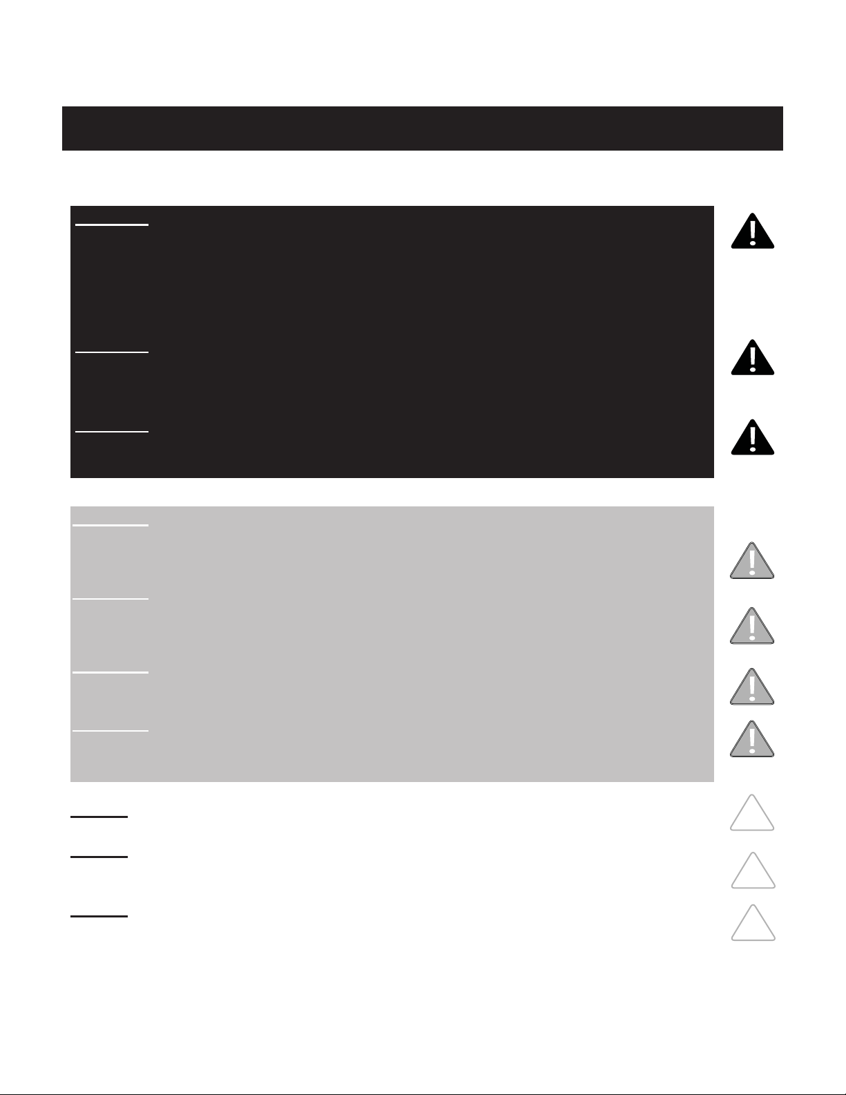
Cook Surface with Protective Cardboard: Lift and separate cook surface from unit and
place next to installation area. Do not remove protective cardboard from cook surface
until installation is complete. Use caution when lifting - the cook surface is heavy.
USE EXTREME CAUTION to ensure wiring on bottom of cook surface does not become
entangled, pulled or damaged during unpacking or installation.
Drip Pan Gasket:
Gasket is secured
to top of drip tray.
Remove gasket
from drip tray
and set aside
for reinstallation.
Drip Pan with
Protective
Cardboard:
Release three
latches inside
circular skirt,
then carefully
lift and separate
drip pan
from unit and
place next to
installation area.
Do not remove
protective
cardboard from
drip pan until
installation is
complete.
Chassis: Lift
chassis from
crating box and
place next to
installation area.
Metal Right Angle Brackets: Remove from unit
and keep handy for fi rst installation step.
3-wire service line: Black, red and
green
UNPACKING COOKTOP COMPONENTS - 1 of 2
STEP 1: As you are unpacking the crate, make sure you locate all components before
installation. Keep all protective cardboard on components until installation is complete.
INSTALLATION INSTRUCTIONS
Affinity 25E
Evo, Inc., 20560 SW 115th Ave., Tualatin, OR 97062 USA
Phone 503.626.1802 | Fax 503.213.5869 | www.evoamerica.com | [email protected]
6
UNPACKING COOKTOP COMPONENTS - 2 of 2
STEP 1 CONTINUED: Take care when lifting the cook surface during uncrating. Do not pull
or damage wires or connections. Store in a safe place until ready to install.
USE EXTREME CAUTION to ensure wiring on bottom of cook surface does not become
entangled, pulled or damaged during unpacking or installation.

INSTALLATION INSTRUCTIONS
Affinity 25E
Evo, Inc., 20560 SW 115th Ave., Tualatin, OR 97062 USA
Phone 503.626.1802 | Fax 503.213.5869 | www.evoamerica.com | [email protected]
7
36” clearance to ceiling from cooktop surface
CLEARANCE DIMENSIONS
12” clearance to sidewall
from cooktop surface
12” clearance to backwall
from cooktop surface
Read the instructions carefully in this booklet to install the
Evo Affi nity 25E Cooktop to a metal, stone or wood countertop surface.
Cabinet layout and construction may vary.
Minimum 3” clearance required under unit
venting to 22 sq/in of combustible air.
Do not install above any equipment, table or shelving where
air temperature is greater than ambient air temperature.
CLEARANCE TO COMBUSTIBLE CONSTRUCTION FROM CHASSIS
Combustibles Non-combustibles
Back 0” 0”
Sides 0” 0”
Bottom 3” 3”
CLEARANCE TO COMBUSTIBLE SURFACE FROM COOKING SURFACE
Top 36”
Sides 12”

INSTALLATION INSTRUCTIONS
Affinity 25E
Evo, Inc., 20560 SW 115th Ave., Tualatin, OR 97062 USA
Phone 503.626.1802 | Fax 503.213.5869 | www.evoamerica.com | [email protected]
8
PP
PP
PP
PP
PP
PP
PP
PP
PP
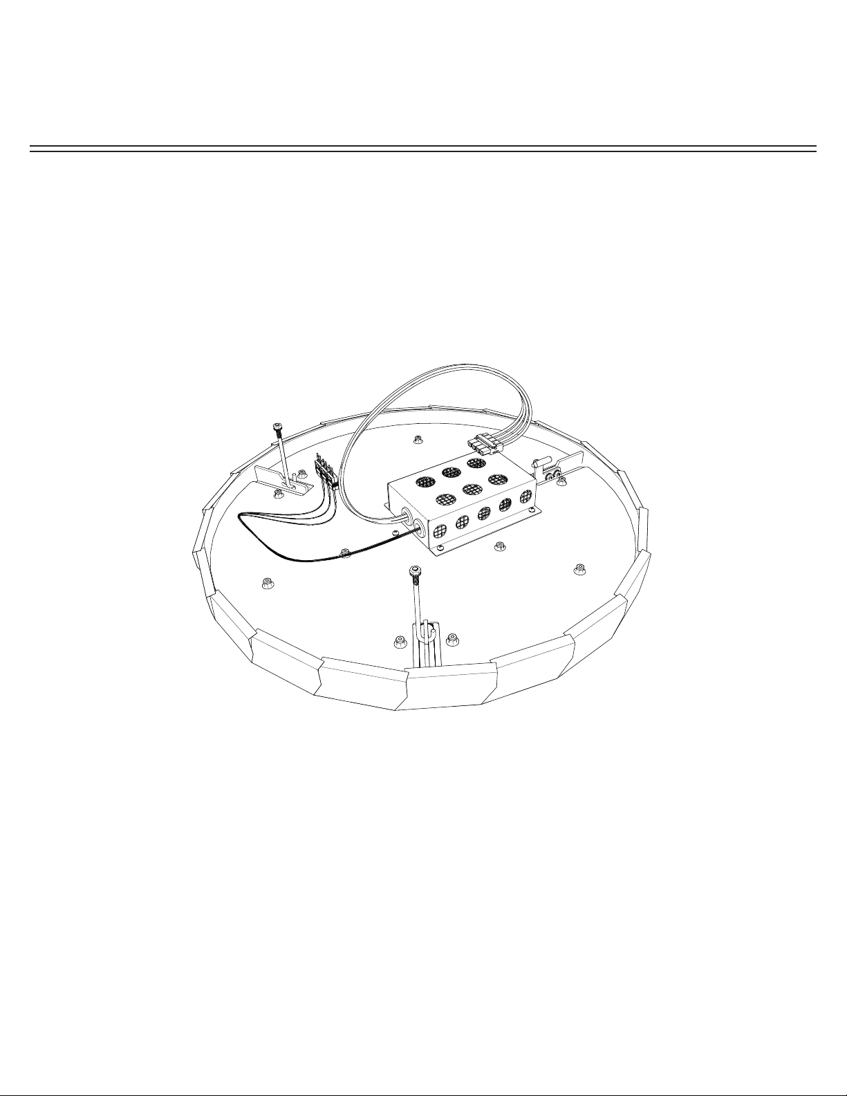
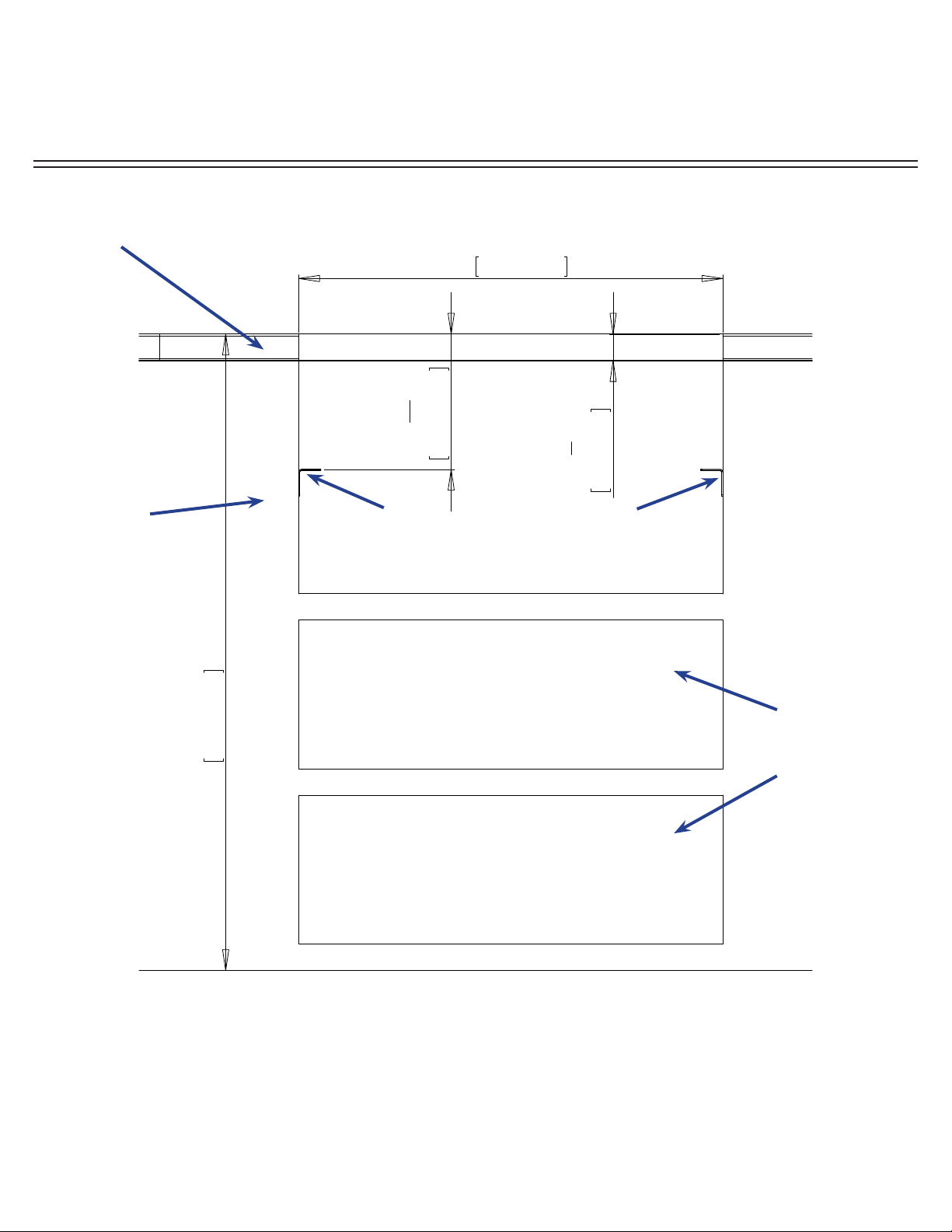
STEP 2: Mark the fi nished position of the Evo Affi nity 25E drip pan on the countertop using
the dimensions shown. The circular dimension of 31-11/16” is the diameter of the drip pan
to the outside fl ange material thickness (located to the inside of the half-rolled bead edge).
The drip pan cutout must be made precisely to these dimensions (or at a maximum +1/16”)
so that the half-rolled top bead on the drip pan edge overhangs the cutout dimension by .25”.
(See following page for more details).
Countertop with substrate
underlayment
OPENING IN COUNTERTOP FRONT
From countertop
front to center of
drip pan cutout.
Cabinetry Box:
1-1/2” below
countertop
surface
TOP VIEW
COUNTERTOP INSTALLATION (1 of 4)
NOTE:
If the dimensions for the
countertop overhang
and countertop depth
cutout are not followed,
there will be a confl ict
with the door swing
which may hinder access
to the spillover waste
containers.
COUNTERTOP
OVERHANG TO
CABINET FRONT

INSTALLATION INSTRUCTIONS
Affinity 25E
Evo, Inc., 20560 SW 115th Ave., Tualatin, OR 97062 USA
Phone 503.626.1802 | Fax 503.213.5869 | www.evoamerica.com | [email protected]
9
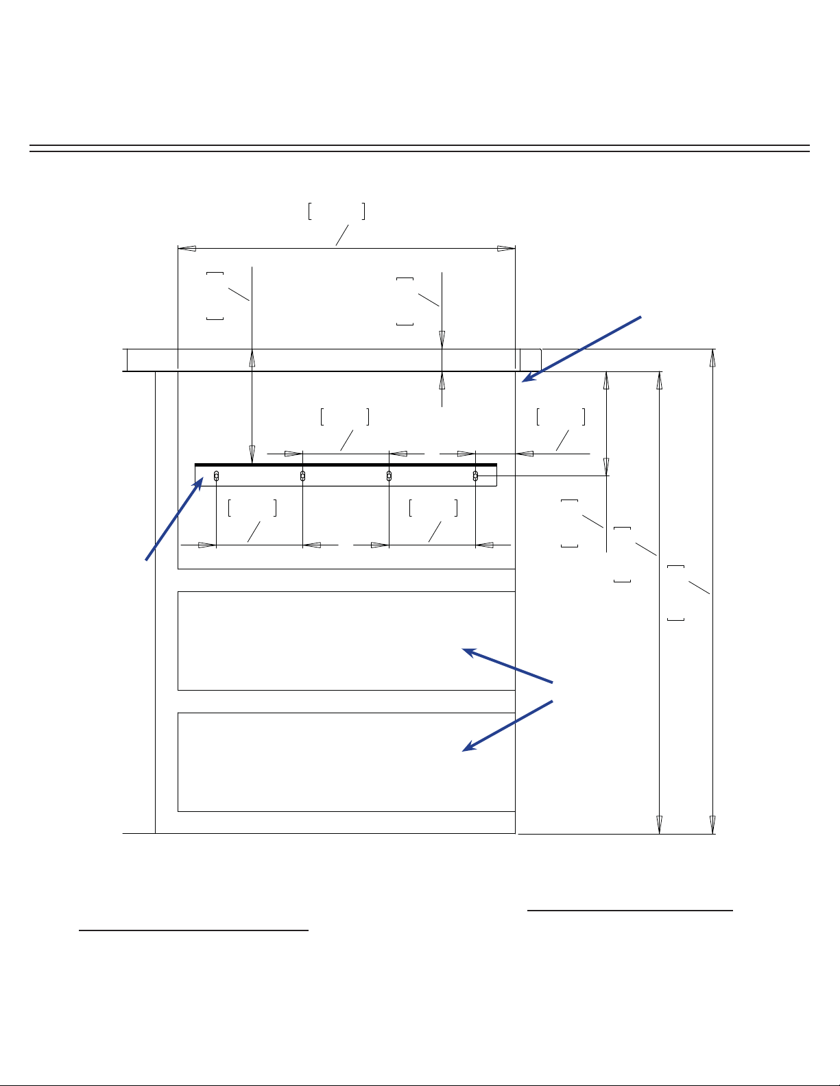
COUNTERTOP INSTALLATION (2 of 4)
STEP 2 continued: Make sure cabinetry box is 1-1/2” below countertop surface and
mounting brackets are positioned correctly so drip pan and chassis are aligned to countertop.
(see diagrams above). A black o-ring is recessed in the top bead and designed to create a
seal against the countertop.
Also ensure allowance for the countertop overhang as shown on the SIDE VIEW (see next
page).
When you have confi rmed the position is correct, cut the countertop and substrate.
CORRECT ALIGNMENT OF DRIP PAN
AND CHASSIS TO COUNTERTOP
INCORRECT ALIGNMENT OF DRIP PAN
AND CHASSIS TO COUNTERTOP
Possible reasons for incorrect alignment:
1. Top of cabinetry box is less than 3 cm
from countertop
2. Chassis mounting brackets are too high.
Black o-ring under
drip pan bead
INSTALLATION INSTRUCTIONS
Affinity 25E
Evo, Inc., 20560 SW 115th Ave., Tualatin, OR 97062 USA
Phone 503.626.1802 | Fax 503.213.5869 | www.evoamerica.com | [email protected]
10
LQ
LQ
LQ
LQ
LQ
LQ
LQ
LQ
LQ
LQ
SIDE VIEW
Example of 3/8” tile with substrate for a total of 1-1/2” overall. Make sure you allow for the
countertop overhang as shown.
Metal Right
Angle
Mounting
Brackets
(supplied)
Shelving or
drawers can
be installed
under
Affi nity 25E if
desired.
Finished cabinet face
set back from fi nished
countertop front edge
COUNTERTOP INSTALLATION (3 of 4)
INSTALLATION INSTRUCTIONS
Affinity 25E
Evo, Inc., 20560 SW 115th Ave., Tualatin, OR 97062 USA
Phone 503.626.1802 | Fax 503.213.5869 | www.evoamerica.com | [email protected]
11
PP
PP
PP
PP
Shelving or
drawers can
be installed
under
Affi nity 25E if
desired.
FRONT VIEW
STEP 3: Construct a bay for the Evo unit with your chosen cabinet system. Position and
fasten the supplied mounting brackets 7-21/32” below the fi nished countertop surface.
Metal right angle mounting brackets supplied with unit are
each 1/16” thick. Mount angle brackets as shown. Unit
slides into framework and rests on top side of brackets.
Brackets are slotted for fasteners at each four corners.
Cabinet
Framework
Example: Tiled countertop with substrate.
Finished countertop thickness should be
1-7/16” to 1-1/2”.
COUNTERTOP INSTALLATION (4 of 4)

INSTALLATION INSTRUCTIONS
Affinity 25E
Evo, Inc., 20560 SW 115th Ave., Tualatin, OR 97062 USA
Phone 503.626.1802 | Fax 503.213.5869 | www.evoamerica.com | [email protected]
12
STEP 4: Slide the Affi nity 25E chassis into the countertop so it rests on top of the installed
brackets. Bolt unit to angle brackets using supplied 1/4” x 20 fasteners from underside.
NOTE: Electrical Installation of the service line must be done by a licensed electrician
in accordance with local guidelines once unit has been completely installed.
3 WIRE SERVICE LINE:
black, red and green
208V / 230V, 30AMP,
1-Phase, 50-60Hz
INSERT CHASSIS IN COUNTERTOP
Use supplied 1/4” fasteners to bolt
chassis to angle brackets.
INSTALLATION INSTRUCTIONS
Affinity 25E
Evo, Inc., 20560 SW 115th Ave., Tualatin, OR 97062 USA
Phone 503.626.1802 | Fax 503.213.5869 | www.evoamerica.com | [email protected]
13
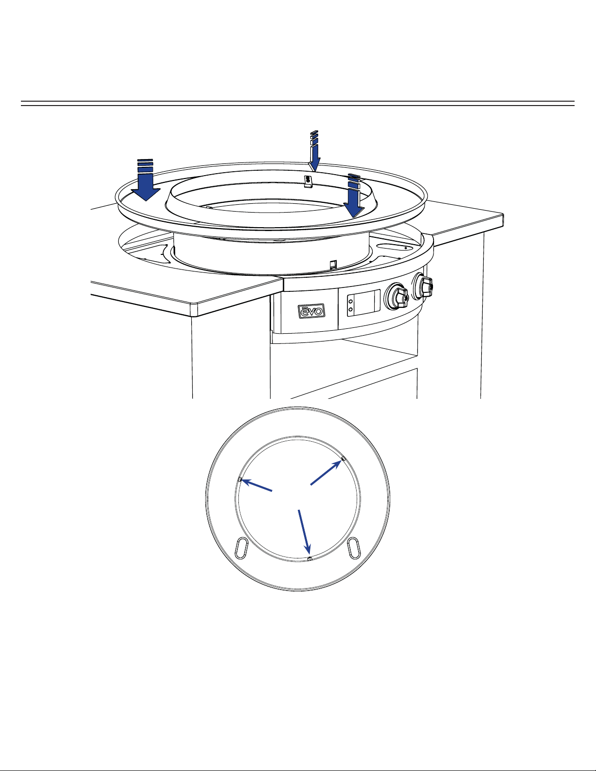
STEP 5: Slide drip tray over chassis circular skirt positioning spillover slots to the
corresponding slots of the top chassis deck. Notice the drip pan catches showing through the
inside cutout locations of the circular chassis skirt. From the inside of the skirt, use each of
the three latches to pull the drip pan down into the counter.
Drip Tray
Catches
DRIP PAN INSTALLATION
GRILL FRONT
INSTALLATION INSTRUCTIONS
Affinity 25E
Evo, Inc., 20560 SW 115th Ave., Tualatin, OR 97062 USA
Phone 503.626.1802 | Fax 503.213.5869 | www.evoamerica.com | [email protected]
14
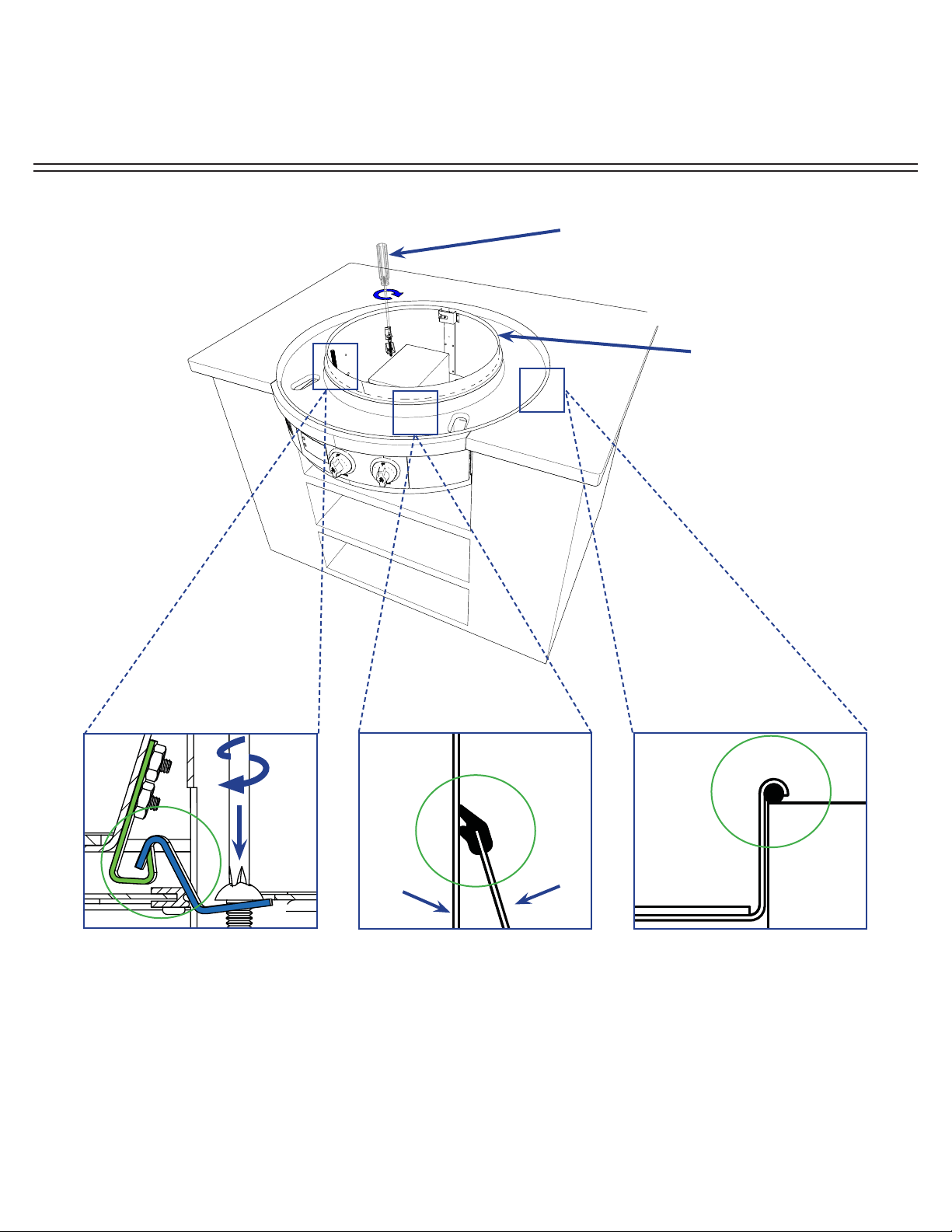
STEP 6: Secure drip pan to chassis using access slot (A). Rewrap drip pan gasket around
top of drip tray and secure (B). Ensure seal under drip pan edge is touching countertop(C).
IMPORTANT: Keep protective cardboard on drip pan until cook surface is installed.
Drip pan gasket seam
at rear of cooktop
(opposite to chef side)
DRIP PAN AND GASKET INSTALLATION
CROSS SECTION OF
CHASSIS ACCESS SLOT
Hook drip pan latch under
chassis catch and tighten
screw at chassis access slot.
A
Slip gasket ring onto top of
drip pan so it creates a seal to
the chassis skirt.
CROSS SECTION OF
DRIP PAN TOP
CROSS SECTION OF
DRIP PAN EDGE
Ensure the black seal under
the drip pan bead edge is
touching the countertop.
BC
drip pan
countertop
drip pan
chassis
skirt
Use No. 3 Phillips screwdriver
to secure drip pan at the
access points.

INSTALLATION INSTRUCTIONS
Affinity 25E
Evo, Inc., 20560 SW 115th Ave., Tualatin, OR 97062 USA
Phone 503.626.1802 | Fax 503.213.5869 | www.evoamerica.com | [email protected]
15
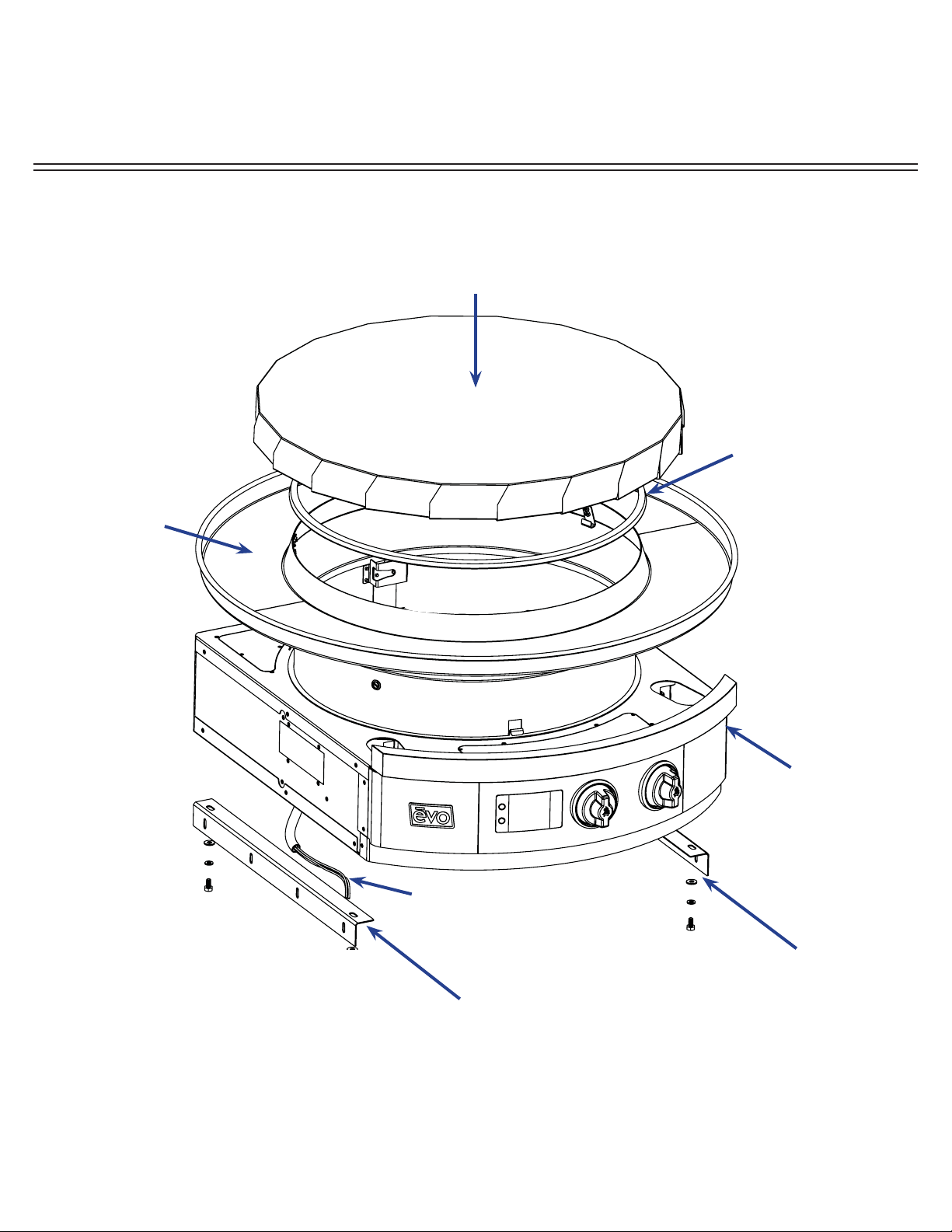
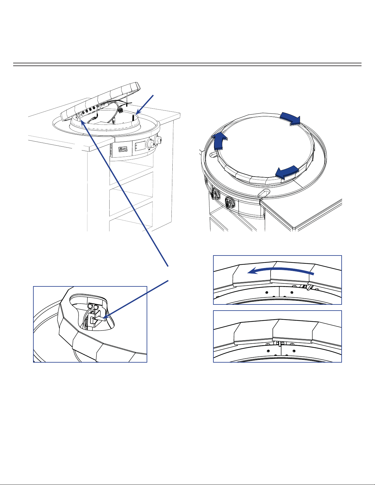
STEP 7: Before picking up cook surface, rotate each of the two front slotted captive fastener
screws counter-clockwise and back them out fully. Rest cook surface at rear of chassis on
drip pan protective cardboard and connect respective power and temperature sensor leads.
For electrical wiring details, refer to the electrical schematic in the back of this guide.
-Temperature Sensor Connection -
Blue Banded Wire = Position 1
Black Banded Wire = Position 2 & 3
(2 & 3 Interchangeable)
Electrical Input
To Cooking Surface
CONNECTING COOK SURFACE - ELECTRICAL CONNECTIONS
1
2
3
INSTALLATION INSTRUCTIONS
Affinity 25E
Evo, Inc., 20560 SW 115th Ave., Tualatin, OR 97062 USA
Phone 503.626.1802 | Fax 503.213.5869 | www.evoamerica.com | [email protected]
16
STEP 8: Place cook surface over circular skirt with the three support tabs (located under
cook surface) resting on the chassis skirt top. Position the rear support tab of the cook
surface to the right of the rear seam of the chassis skirt (A). Then rotate the cook surface
clockwise until the support tab is in line with the seam (B) and the rear bullet secures in the
chassis slot (C) .
INSTALLING COOK SURFACE
BOTTOM-UP VIEW OF
REAR COOK SURFACE
CUT AWAY VIEW OF REAR COOK
SURFACE SHOWING BULLET
ENGAGED IN CHASSIS SLOT
A
B
C
Rear Bullet
Cook surface tie-down J-hooks pass through tubes
allowing threaded end of J-hook to extend into spillover
tray enclosure and be secured with 1/4”x20 nut at each
right and left sides.

INSTALLATION INSTRUCTIONS
Affinity 25E
Evo, Inc., 20560 SW 115th Ave., Tualatin, OR 97062 USA
Phone 503.626.1802 | Fax 503.213.5869 | www.evoamerica.com | [email protected]
17
INSTALLING COOK SURFACE
Remove protective cardboard
from cook surface and drip pan
STEP 9: Open spillover tray doors and tighten nut on end of j-hook located at inside rear of
each door.
Complete electrical installation by connecting 3-wire service line located underneath unit. Use
electrical schematic diagram at the back of this guide for reference.
Open spillover tray doors to locate end of
j-hook and secure with 1/4” x 20 nut.
Tighten 1/4” x 20 nut at end of each j-hook
to secure cooking surface to chassis.
OPERATOR INSTRUCTIONS
Affinity 25E
Evo, Inc., 20560 SW 115th Ave., Tualatin, OR 97062 USA
Phone 503.626.1802 | Fax 503.213.5869 | www.evoamerica.com | [email protected]
18
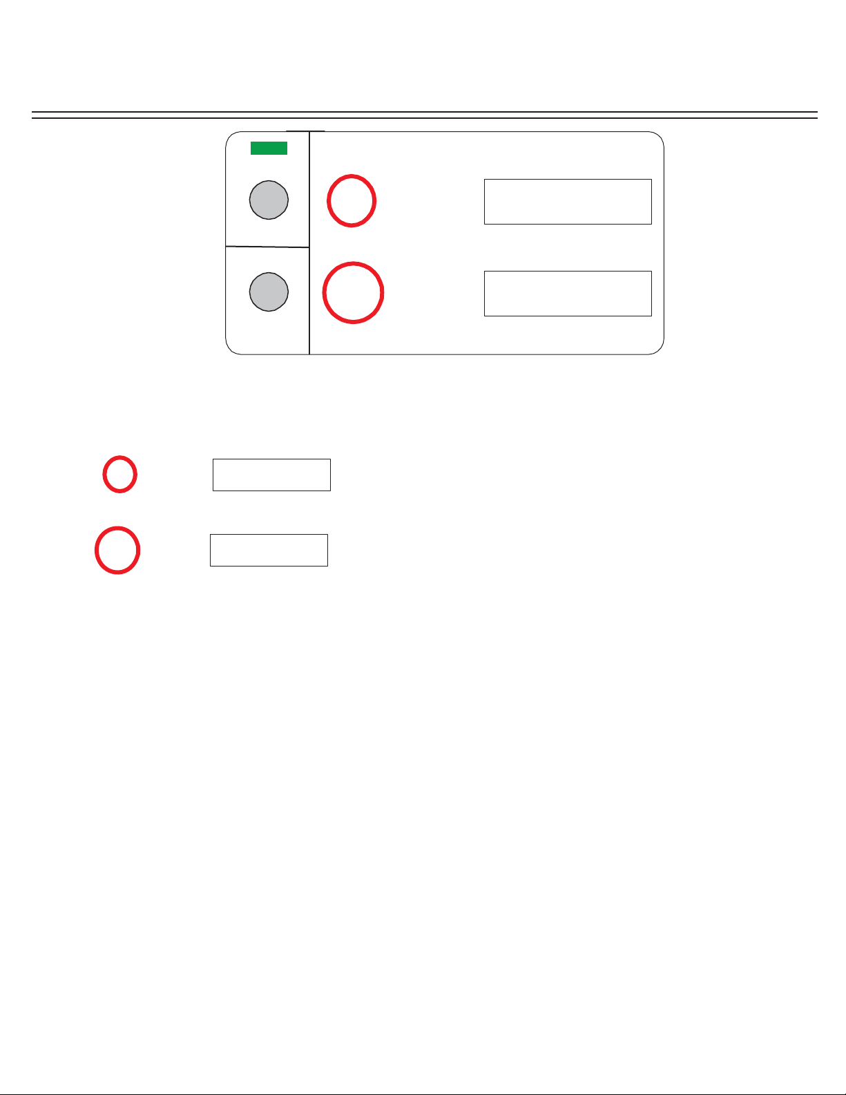
INNER
000F .
Displays temperature for Inner heater element in Fahrenheit degrees
whenever Inner control knob is selected. The Dot mark after F is
illuminated whenever the inner heater element is energized. Inner
display remains illuminated whenever Inner heater element is selected.
OUTER
000F .
Displays temperature for Outer heater element in Fahrenheit degrees
whenever Outer control knob is selected. The Dot mark after F is
illuminated whenever the outer heater element is energized. Outer
display remains illuminated whenever Outer element is selected.
Depressing the round switch located below the On/Off label switches the unit between power
On and power Off states. Switching the unit On illuminates a green light above the On/Off
label indicating the unit is active. Depressing the switch a second time powers down the unit,
and cancels previous settings.
On/Off
Is illuminated whenever there is an increase in temperature adjustment to the Inner or
Outer heater control knobs. Set remains illuminated until temperature selected is achieved.
SET
Is illuminated as a safety feature to indicate cook surface temperature are in excess of
150F° or greater.
HOT SURFACE
Is illuminated to show actual temperature for both Inner and Outer heater element
whenever Mode switch is selected.
ACTUAL
Depressing the Mode button momentarily displays the actual temperature at both Inner
and Outer zones of the cook surface. When Mode is fi rst selected, the word Actual is
illuminated to indicate the temperatures displayed are the current temperatures for Inner
and Outer zones.
Mode
The Affi nity 25E Commercial cooktop is provided with a COOK Mode that offers a
temperature range between 150F to 525F:
Low 150, 165, 175, 200, 225, 250.
Med 275, 300, 325, 350, 375, 400.
Hi 415, 425, 450, 475, 500, 525.
Temperatures
SET
HO T SUR FA CE
AC TU AL
INNER
OUTER
000F .
000F .
COOK
Mode
On/Off
WARM
EVO AFFINITY 25E ELECTRIC CONTROL PANEL DISPLAY
OPERATOR INSTRUCTIONS
Affinity 25E
Evo, Inc., 20560 SW 115th Ave., Tualatin, OR 97062 USA
Phone 503.626.1802 | Fax 503.213.5869 | www.evoamerica.com | [email protected]
19
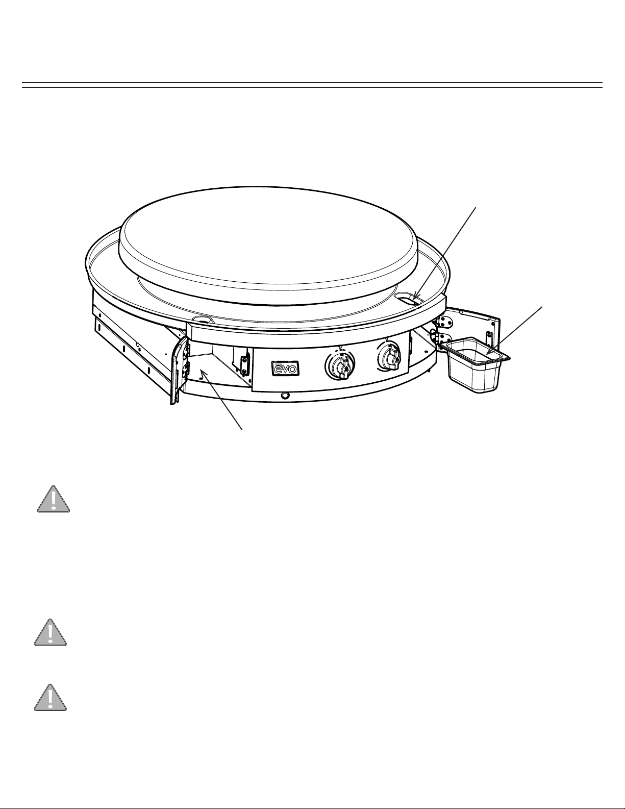
REMOVABLE SPILLOVER TRAYS
The Affi nity grill has removable waste pans concealed in doors on both the right and left side of the front control panel.
It is very important to monitor the level of spillover in the trays, and immediately empty when they are near full or after
each use.
Opening Spillover Tray Doors - To open a door, grasp the door at its bottom and pull forward.
Do not operate cook top or clean drip pan into spillover slots without waste pans installed in
spillover doors. Failure to install waste pan will result in cooking grease contamination to the
underside of door. This requires immediate cleaning.
Removable waste pan
Access
Door
Spillover Slot
Insert each waste pan all the way to the
back of the left and right compartments.
Do not allow spillover liquids or debris down spillover slots when doors are open. Any liquids or
debris that may fall into this area when doors are open should be immediately wiped with a dry
cloth, and keep this area clean at all times.
Do not allow the spillover trays to overfl ow, and do not allow full trays to splash over edge when
cleaning. Spillover debris and liquids can be hot and cause burns, and/or damage to the internal
operation of the grill.

OPERATOR INSTRUCTIONS
Affinity 25E
Evo, Inc., 20560 SW 115th Ave., Tualatin, OR 97062 USA
Phone 503.626.1802 | Fax 503.213.5869 | www.evoamerica.com | [email protected]
20
Regular cleaning and care for your Evo Affi nity 25E cooktop will keep it looking and functioning it’s best.
The cook surface is designed to hold a fi ne layer of cooking oil creating a ‘seasoning’ on its surface. This
seasoning promotes a non-stick cooking surface and is easily maintained.
Caring for Evo’s cook surface is much like maintaining cast iron cookware. When the surface requires cleaning,
there are a few basic cleaning techniques to use. For quick and routine cleaning between preparations, a metal
spatula or scraper works for removing the majority of surface debris. For tougher areas or where sugars glaze
the cook surface, pour a small amount of warm water on the soiled surface while the grill is warm and scrape the
debris away with a spatula. Heat the cook surface to a high temperature and allow the sticky debris to become
brittle. Once the debris is brittle, use the spatula or scraper to remove it. Afterwards wipe the cook surface with
vegetable oil again before cooking.
To condition the Evo cook surface you should use the grill cleaning kit supplied with your grill. The grill cleaning kit
contains a blue grill pad handle, grill cleaning screens, and grill grey polishing pads. Use the polishing pad after
the grill cleaning pads to achieve a smooth cooking surface for the most delicate foods and applications.
To use a grill cleaning screen: With a warm cook surface, place one gray polishing pad between the grill handle
base and the grill screen, so the grill screen makes direct contact with the cooking surface. Pour a small amount
of vegetable oil on the cook surface and scrub the surface in a circular motion. The gray polishing pad allows
excess oil to be absorbed and scours the cooking surface of carbonized debris. When fi nished scrubbing, wipe
the surface down with a paper towel or cotton terry cloth.
The drip pan located just below the cook surface is designed to catch food debris and drippings from the cook
surface. We recommend cleaning the drip pan after your grill has cooled to prevent the possibility of touching
hot adjoining surfaces. The drip pan is easy to wipe out with soap and water using a kitchen sponge. For added
convenience, two removable stainless ninth-pans are mounted inside doors at right and left side of the front control
panel for collecting drip pan debris and spill overs. These spillover trays can be easily washed by hand or in a
dishwasher. Be sure to empty the spillover trays after every use, and at a minimum, whenever they appear half
full.
All the stainless steel components on your grill can be easily polished using a stainless steel cleaner/polish.
Information about purchasing replacement grill cleaning and polishing pads is available on our Website. The Evo
web site address is: www.evoamerica.com.
Cooking Techniques
Stovetop Cooking and Heat Zones
You can use Evo’s cook surface similar to the burners on your kitchen stove top. Adjust Evo’s heater elements to
control the temperatures of the cook surface “heat zones.” Evo’s circular grill top is divided into two distinct zones.
The center control panel knob controls the “inner heat zone,” which is also the inner circle of the cook surface at
approximately an 11” radius from the center of the cook surface. The outer control panel knob controls the “outer
heat zone,” which is the outer circle of the cook surface. Because the cook surface is made of heavy steel, it takes
approximately 10 minutes from a cold start to completely heat the surface. With a pre-heated cook surface, if you
adjust one of the heater elements, you will have to wait momentarily before the heat zone adjusts to temperature.
Thank You For Cooking With Evo!
COOK SURFACE MAINTENANCE
INSTALLATION INSTRUCTIONS
Affinity 25E
Evo, Inc., 20560 SW 115th Ave., Tualatin, OR 97062 USA
Phone 503.626.1802 | Fax 503.213.5869 | www.evoamerica.com | [email protected]
21
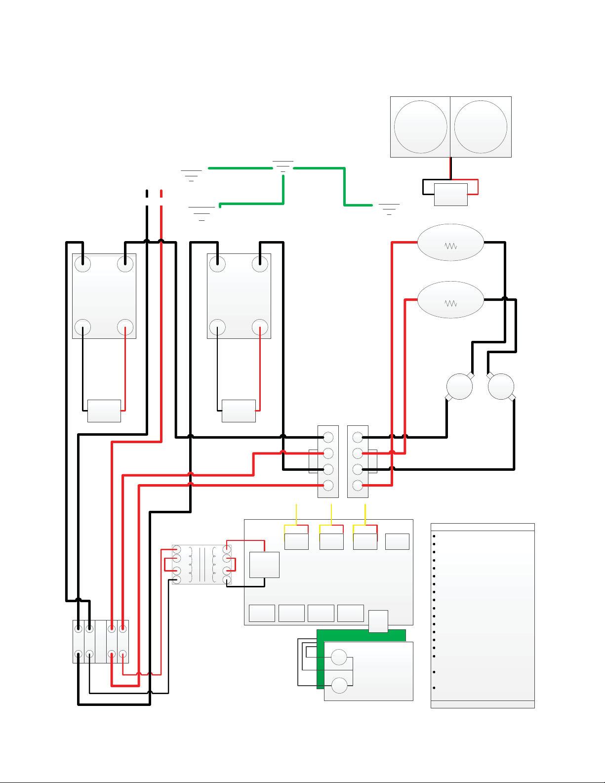
CPU
SSR
1/L1
2/T1
4/A2 +3/A1
50AMP 48-660VAC
4-32VDC
SSR
1/L1
2/T1
4/A2 +3/A1
50AMP 48-660VAC
4-32VDC
12
34
56
78
1
2
5
6
7
8
11
12
L2L1
4
3
2
1
INNER
12vdc
OUTER1
12vdc
OUTER 3
12vdc
12VDC FAN 12VDC FAN
CPU
POWER
12vac
4
3
2
1
INNER HEATER
19.2
ё
OUTER HEATER
8.3
ё
SSR1
Z1
Z2
T1
SD
SD
T2
SD
SD
CSG
EG
CG
SSR2
ENG
OUTPUTS
INPUTS
INNER
12vdc
OUTER 1
12vdc
OUTER 2
unused
OUTER 3
12vdc
Inner
TC (K)
+
Outer 1
TC (K)
+
Outer 2
TC (K)
+
Outer 3
unused
+
RC
D1
D2
TX
TB
J1 P1
EG: Earth Ground
CG: Chassis Ground
CSG: Cook Surface Ground
ENG: Enclosure Ground
SSR1: Inner Control Relay
SSR2: Outer Control Relay
Z1: Inner Heat Zone
Z2: Outer Heat Zone
T1: Inner Auto Reset Snap Disc
T2: Outer Auto Reset Snap Disc
TB: Terminal Block
TX: Transformer
CPU: Central Processing Unit
RC: Display Ribbon Cable
D1: LED Display Board
D2: Display Overlay (w/dome
switches)
J1: Panel Mount Housing
Molex #428180412
P1: Locking Housing
Molex #428160412
208-220VAC
1Phase
30Amp dedicated
On/off
Mode
30AMP ELECTRICAL SCHEMATIC
PART #: 10-0062-EL & 10-0061-EL
208V - 230V, 1-Phase, 50-60Hz
30AMP Dedicated Circuit
208V / 5.37 kVA
230V / 6.56 KVA