OWNER & INSTALLATION MANUAL
A f f i n i t y 3 0 G
C o o k t o p
Evo, Inc., 20560 SW 115th Ave., Tualatin, OR 97062 USA
Phone 503.626.1802 | Fax 503.213.5869 | www.evoamerica.com | [email protected]
Certifi cation: ANSI Z83.11-2016 / CSA 1.8-2016
OMNI Report # 0141GM003S
Part #: Commercial Models: 10-0054-NG, 10-0054-LP
Residential Models: 10-0055-LP, 10-0055-NG
Doc: 1-22-2020 Copyright © 2020
Tested &
Listed By
Portland
Oregon USA
Pour obtenir un manuel en français, veuillez appeler Evo, Inc. au 503-626-1802.
For a French Language Manual, please call Evo, Inc. at 503-626-1802.
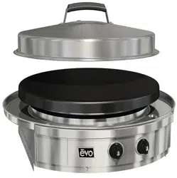
Evo Affi nity 30G
Gas Cooktop
For Outdoor Use Only
INSTALLATION INSTRUCTIONS
A f f i n i t y 3 0 G
Evo, Inc., 20560 SW 115th Ave., Tualatin, OR 97062 USA
Phone 503.626.1802 | Fax 503.213.5869 | www.evoamerica.com | [email protected]
2
THIS MANUAL MUST BE RETAINED FOR FUTURE REFERENCE. READ, UNDERSTAND,
AND FOLLOW THE INSTRUCTIONS AND WARNINGS CONTAINED IN THIS MANUAL.
DANGER
POTENTIALLY HAZARDOUS SITUATION WHICH, IF NOT
AVOIDED, COULD RESULT IN DEATH
CAUTION
POTENTIALLY HAZARDOUS SITUATION WHICH, IF NOT AVOIDED,
MAY RESULT IN MINOR OR MODERATE INJURY.
WARNING
POTENTIALLY HAZARDOUS SITUATION WHICH, IF NOT AVOIDED,
COULD RESULT IN DEATH OR SERIOUS INJURY
CAUTION
Helpful tips and technique instructions are shown.
Notes
Complete Now For Future Reference
Model #_______________________________ Serial # _________________________________
Date Purchased ________________________ Location Purchased _______________________
Date Installed __________________________ Location Installed _________________________
To Installer or Person Uncrating Grill:
Leave these instructions with purchaser.
To Purchaser:
Keep these instructions for future reference.
INSTALLATION INSTRUCTIONS
A f f i n i t y 3 0 G
Evo, Inc., 20560 SW 115th Ave., Tualatin, OR 97062 USA
Phone 503.626.1802 | Fax 503.213.5869 | www.evoamerica.com | [email protected]
3
WARNING
This symbol identifi es the most important
safety messaging in this manual. When you
see this symbol, be alert to the possibility of
serious bodily injury if the instructions are
not followed. Be sure to read and carefully
follow all of the messages.
Grill should only be used outdoors, in a well ventilated space, and should not be used in a
building, garage, or any other enclosed area. Never operate near fl ammable liquids or vapors.
Do not install or use grill within 36” of combustible ceiling materials, and 12” from back and
sides of grill. Grill shall not be located under unprotected overhead made of combustible
construction within 36” from top of grill. Do not obstruct the fl ow of combustion and ventilation
air, including ventilation of cylinder enclosures, if applicable.
WARNING
Warnings
FOR YOUR SAFETY
If You Smell Gas:
1. Shut off gas to appliance.
2. Extinguish any open fl ame.
3. Remove grill cooking surface.
4. If odor continues, immediately call your
gas supplier or your fi re department.
5. Evacuate all personnel from the area.
FOR YOUR SAFETY
1. Do not store or use gasoline or other
fl ammable vapors and liquids in the
vicinity of this or any other appliance.
2. An LP Tank not connected for use shall
not be stored in the vicinity of this or
any other appliance.
It is the responsibility of the assembler/owner
to assemble, install and maintain gas grill.
Do not let children operate or play near your
grill. Failure to follow these instructions could
result in serious personal injury and / or
property damage.
WARNING
Improper installation, adjustment, alteration, service or maintenance can cause property
damage, injury or death. Read the installation, operating and maintenance instructions
thoroughly before installing or servicing this equipment.
WARNING
INSTALLATION INSTRUCTIONS
A f f i n i t y 3 0 G
Evo, Inc., 20560 SW 115th Ave., Tualatin, OR 97062 USA
Phone 503.626.1802 | Fax 503.213.5869 | www.evoamerica.com | [email protected]
4
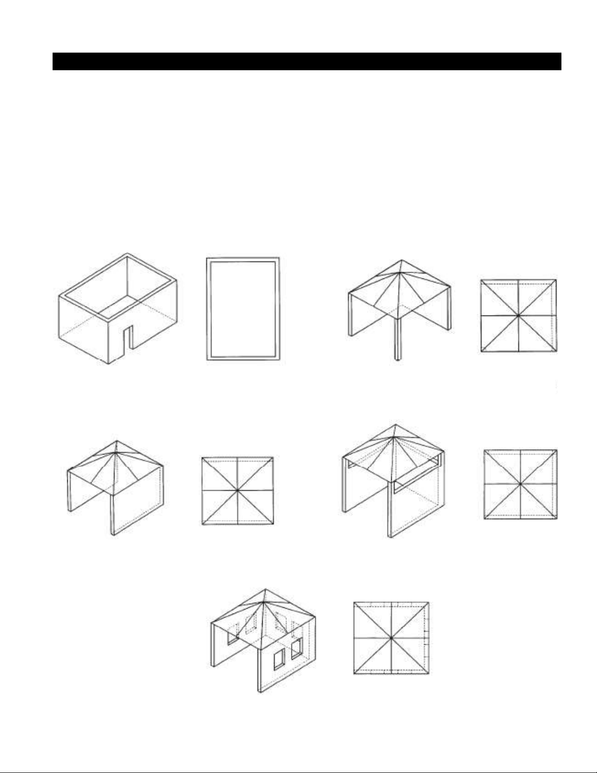
Use Outdoors Only
Figure 1 - Enclosure with walls on all sides but
no overhead cover.
Figure 2 - Partial Enclosure with overhead cover and
no more than two walls.
Figure 3 - Partial Enclosure with overhead cover and
no more than two walls.
This appliance shall only be used in an above ground open-air situation with natural ventilation, without stagnant areas, where gas
leakage and products of combustion are rapidly dispersed by wind and natural convection.
Any enclosure in which the appliance is used shall comply with one of the following:
• An enclosure with walls on all sides, but at least one permanent opening at ground level and no overhead cover. See Figure1.
• Within a partial enclosure that includes and overhead cover and no more than two walls. See Figure 2 & 3.
• Within a partial enclosure that includes an overhead cover and more than two, the following shall apply:
-At least 25% of the total wall area is completely open; and
-At least 30% of the remaining wall area is open and unrestricted. See Figure 4 & 5.
• In the case of balconies, at least 20% of the total side, back and front areas shall be and remain open and unrestricted.
The following diagrams provide a diagrammatic representation of outdoor areas. Rectangular areas have been used in these
fi gures - the same principles apply to any other shaped area.
Figure 4 - Open side at least 25% of total wall area.
30% or more intotal of the remaining wall area is
open and unrestricted
This appliance is not intended to be installed in or on boats, and is not intended to be
installed in or on recreational vehicles.
INSTALLATION INSTRUCTIONS
A f f i n i t y 3 0 G
Evo, Inc., 20560 SW 115th Ave., Tualatin, OR 97062 USA
Phone 503.626.1802 | Fax 503.213.5869 | www.evoamerica.com | [email protected]
5
READ FIRST
IMPORTANT PRODUCT AND SAFETY INFORMATION
WARNING INSTALLATION OF THIS UNIT MUST BE DONE BY A QUALIFIED PLUMBER.
INCORRECT INSTALLATION CAN CAUSE INJURY TO PERSONNEL AND/
OR DAMAGE TO EQUIPMENT. THIS UNIT MUST CONFORM WITH ALL
LOCAL CODES, OR IN THE ABSENCE OF LOCAL CODES, WITH THE
NATIONAL FUEL GAS CODE, ANSI Z223.1/NFPA 54, OR THE NATURAL
GAS AND PROPANE INSTALLATION CODE, CSA B149.1, AS APPLICABLE
INCLUDING:
1. THIS UNIT AND ITS INDIVIDUAL SHUTOFF VALUE MUST BE
DISCONNECTED FROM THE GAS SUPPLY PIPING SYSTEM DURING ANY
PRESSURE TESTING OF THE SYSTEM AT TEST PRESSURES IN EXCESS
OF 1/2 PSI (3.45 kPa).
2. THIS UNIT MUST BE ISOLATED FROM THE GAS SUPPLY PIPING
SYSTEM BY CLOSING ITS INDIVIDUAL MANUAL SHUTOFF VALVE DURING
ANY PRESSURE TESTING OF THE GAS SUPPLY PIPING SYSTEM AT TEST
PRESSURES EQUAL TO OF LESS THAN 1/2 PSI (3.5 kPa).
WARNING DO NOT DIRECTLY INSTALL THIS UNIT TO COMBUSTIBLE SURFACES,
AND DO NOT USE COMBUSTIBLE MATERIALS IN THE CONSTRUCTION
OF ANY COUNTER, STAND, OR OTHER DEVICE WHICH WILL COME INTO
DIRECT CONTACT WITH THE BURNER CHASSIS (SEE PAGE
WARNING IMMEDIATELY AFTER CONNECTING GAS SUPPLY LINE AND BEFORE
FIRST IGNITION, CHECK ALL GAS CONNECTIONS WITH SOAPY WATER
TO TEST FOR LEAKS.
WARNING KEEP WATER AND ALL COOKING SPILL OVERS AWAY FROM FRONT
CONTROL PANEL AND ALL OPEN SERVICE AREAS. NEVER HOSE UNIT,
OR SPRAY UNIT WITH PRESSURIZED CLEANING SOLUTIONS.
CAUTION CAREFULLY FOLLOW ALL INSTALLATION INSTRUCTIONS AND
CONSTRUCT ALL COUNTER SPACE, STANDS, OR OTHER SURFACES TO
THE RECOMMENDED INSTALLATION SPECIFICATIONS AS OUTLINED IN
THIS MANUAL.
CAUTION THIS UNIT IS HEAVY AND SHOULD BE INSTALLED BY TWO PEOPLE.
USE NECESSARY BLOCKING FOR LOCATING AND INSTALLING COOK
SURFACE.
CAUTION ALWAYS KEEP ANY AND ALL FLAMMABLE LIQUIDS AND COMBUSTIBLE
MATERIALS AWAY FROM UNIT. DO NOT STORE TOWELS OR UTENSILS,
OR ANY OTHER ITEMS ON UNIT’S DRIP PAN.
CAUTION DO NOT CLEAN THE COOK SURFACE WITH GRILL BRICKS OR CLEANING
SOLUTIONS. USE ONLY GRILL SCREENS AND GRILL PADS AND FOLLOW
THE PRESCRIBED METHOD OF CLEANING AS OUTLINED IN THIS
MANUAL.
NOTICE THE SERIAL NUMBER AND MODEL INFORMATION LABEL PLATE IS
LOCATED INSIDE THE RIGHT-SIDE SPILLOVER DOOR.
NOTICE INSTALLATION OF ANY VENT HOODS OR FIRE EXTINGUISHER SYSTEMS
MUST CONFORM TO THE NATIONAL, STATE, AND LOCAL BUILDING AND
ALL APPLICABLE UNIFORM CONSTRUCTION CODES.
NOTICE DURING THE FIRST FEW HOURS OF OPERATION IT IS NORMAL FOR OILS
USED IN THE MANUFACTURING PROCESS TO BURN OFF AND GIVE AN
ODOR OR SLIGHT PETROLEUM SMOKE.

INSTALLATION INSTRUCTIONS
A f f i n i t y 3 0 G
Evo, Inc., 20560 SW 115th Ave., Tualatin, OR 97062 USA
Phone 503.626.1802 | Fax 503.213.5869 | www.evoamerica.com | [email protected]
6
EVO RESIDENTIAL LIMITED WARRANTY TERMS
Evo, Incorporated warrants to the original residential consumer-purchaser that the Evo grill shall be free from rust-through on all
metal surfaces and shall be free from defects in materials and workmanship under normal and reasonable use from the original
date of purchase. Evo promises to replace, at its determination, any product or component that is defective and covered under
this warranty for as long as you, the registered original consumer-purchaser, owns the grill. This is your sole and exclusive
remedy. This warranty is for the benefi t of the original consumer-purchaser and is non-transferable. This warranty is subject to the
limitations, exclusions and other provisions listed below.
Limitations Involving Materials and Components:
Warranty does not apply to normal wear and tear, which are expected over the course of ownership. The materials and
components listed below are covered according to the following schedule from the original date of purchase:
• One Year – electrical and electronic components [including, but not limited to, electronic displays, overlay and membrane
switches, temperature sensors (RTD and K-Value Thermal Couple), hot surface igniters, computers, transformers,
heater elements, relays, igniters, ignition controllers, wiring, switches, encoders, outlets and plugs]
• One Year – gas components [including, but not limited to, gas regulator, gas hoses, manifold assemblies]
• One Year – accessories and repair parts
The Warranty Registration Card (or online warranty registration form available at www.evoamerica.com) must be
completed and returned/submitted to Evo, Incorporated within 30 days from the date of purchase. The original purchase
invoice or payment record must be retained and produced upon request if claims are made under this warranty. To
receive a replacement Warranty Registration Card, write or call the address listed at the bottom of this page. Warranties
are void if the original serial numbers have been removed, altered, or cannot be readily determined.
THIS WARRANTY APPLIES ONLY TO PRODUCTS PURCHASED AND LOCATED WITHIN THE UNITED STATES
OR CANADA.
WHAT IS NOT COVERED BY THIS WARRANTY
1. Conditions and damages resulting from any of the following:
a. Improper or inadequate installation, delivery, use, storage or maintenance
b. Any repair not authorized in writing by Evo, Inc., any modifi cations, misapplications, or unreasonable use
c. Improper setting of any control
d. Harsh environmental conditions, including, but not limited to, continual seawater spray, high pressure water, and direct contact
with corrosive chemicals and materials
e. Excessive or inadequate electrical, or gas supply
f. Accidents, natural disasters, acts of God
g. Conditions covered by the purchaser’s insurance
h. Cleaning supplies and fi lters
2. Products purchased or utilized for commercial use without the express authorization of Evo, Incorporated for such use
3. Labor not pre-authorized by Evo, Incorporated, and labor not performed by an authorized Evo service agency or representative
4. Pre-authorized warranty labor performed outside of normal business hours, and at overtime and premium rates
5. The cost of service or a service call to:
a. Identify or correct installation errors
b. Transport the product or component for service to/from the manufacturer or service center
c. Instruct the user of the proper use of the product
6. The cost for any inconvenience, personal injury or property damage due to failure of the product, and cost of damage arising out
of the transportation of the product which is covered under diff erent terms with the carrier
7. Natural variations in color and fi nishes that are inherent to the material and unavoidable (and therefore not defects)
ALL IMPLIED WARRANTIES, INCLUDING THE IMPLIED WARRANTIES OF MERCHANTABILITY, SUITABILITY,
QUALITY AND/OR FITNESS FOR A PARTICULAR PURPOSE, ARE LIMITED IN DURATION TO THE EXPRESS
WARRANTY PERIODS SPECIFIED ABOVE FOR THE PARTS DESCRIBED THEREIN. EVO, INCORPORATED
MAKES NO OTHER WARRANTY AND WILL NOT BE LIABLE FOR ANY DIRECT OR INDIRECT, CONSEQUENTIAL
OR INCIDENTAL DAMAGES. Some states do not allow limitations on how long an implied warranty lasts, so the above
limitation may not apply to you. Neither Evo manufacturer representatives and dealers, nor the retail establishment selling this
product has any authority to make any warranties or to promise remedies in addition to or inconsistent with those stated above.
The maximum liability to Evo, Incorporated in any event, shall not exceed the purchase price of the product paid by the original
consumer-purchaser. Some states do not allow the exclusion or limitation of incidental or consequential damages, so the above
limitations or exclusions may not apply to you. This warranty gives you specifi c legal rights, and you may also have other rights
which vary from state to state.

INSTALLATION INSTRUCTIONS
A f f i n i t y 3 0 G
Evo, Inc., 20560 SW 115th Ave., Tualatin, OR 97062 USA
Phone 503.626.1802 | Fax 503.213.5869 | www.evoamerica.com | [email protected]
7
Evo, Incorporated warrants to the original commercial foodservice purchaser that the Evo cooking, refrigeration and ventilation
equipment shall be free from rust through on all metal surfaces and shall be free from defects in materials and workmanship under
normal and reasonable use for One Year from the original date of purchase from Evo, Inc. This warranty is for the benefi t of the
original use purchaser and is non-transferable. Evo promises to replace, at its determination, any product or component that is
defective during this initial one year period. Or as a resolution, Evo may at its option repurchase the product at its original purchase
price. This is your sole and exclusive remedy. This warranty is subject to the limitations, exclusions and other provisions listed
below.
Limitations Involving Materials and Components:
Warranty does not apply to normal wear and tear, which are expected over the course of ownership. The materials and
components listed below are covered according to the following schedule from the original date of purchase
from Evo:
• One Year – electrical and electronic components [including, but not limited to, electronic displays, overlay and membrane
switches, temperature sensors (RTD and K-Value Thermal Couple), hot surface igniters, computers, transformers,
heater elements, relays, igniters, ignition controllers, wiring, switches, encoders, outlets and plugs]
• One Year – gas components [including, but not limited to, gas regulator, gas hoses, manifold assemblies]
• One Year – accessories and repair parts
• Ninety (90) Days - refrigeration components [including, but not limited to, compressor, evaporator, pressure control
units]
The Warranty Registration Card (or online warranty registration form available at www.evoamerica.com) must be
completed and returned/submitted to Evo, Incorporated within 30 days from the date of purchase. The original purchase
invoice or payment record must be retained and produced upon request if claims are made under this warranty. To
receive a replacement Warranty Registration Card, write or call the address listed at the bottom of this page. Warranties
are void if the original serial numbers have been removed, altered, or cannot be readily determined.
THIS WARRANTY APPLIES ONLY TO PRODUCTS PURCHASED AND LOCATED WITHIN THE USA OR
CANADA.
WHAT IS NOT COVERED BY THIS WARRANTY:
1. Conditions and damages resulting from any of the following:
a. Improper or inadequate installation, delivery, use, storage or maintenance
b. Any repair not authorized in writing by Evo, Inc., any modifi cations, misapplications, or unreasonable use
c. Improper setting of any control
d. Harsh environmental conditions, including, but not limited to, continual seawater spray, high pressure water, and direct contact
with corrosive chemicals and materials
e. Excessive or inadequate electrical, gas, or refrigeration supply
f. Accidents, natural disasters, acts of God
g. Conditions covered by the purchaser’s insurance
h. Cleaning supplies and fi lters
2. Labor not pre-authorized by Evo, Incorporated, and labor not performed by an authorized Evo service agency or
representative
3. Pre-authorized warranty labor performed outside of normal business hours, and at overtime and premium rates
4. The cost of service or a service call to:
a. Identify or correct installation errors
b. Transport the product or component for service to/from the manufacturer or service center
c. Instruct the user of the proper use of the product
5. The cost for any inconvenience, personal injury or property damage due to failure of the product, and cost of
damage arising out of the transportation of the product which is covered under diff erent terms with the carrier
6. Natural variations in color and fi nishes that are inherent to the material and unavoidable (and therefore not defects)
ALL IMPLIED WARRANTIES, INCLUDING THE IMPLIED WARRANTIES OF MERCHANTABILITY, SUITABILITY, QUALITY
AND/OR FITNESS FOR A PARTICULAR PURPOSE, ARE LIMITED IN DURATION TO THE EXPRESS WARRANTY PERIODS
SPECIFIED ABOVE FOR THE PARTS DESCRIBED THEREIN. EVO, INCORPORATED MAKES NO OTHER WARRANTY AND
WILL NOT BE LIABLE FOR ANY DIRECT OR INDIRECT, CONSEQUENTIAL OR INCIDENTAL DAMAGES. Some states do not
allow limitations on how long an implied warranty lasts, so the above limitation may not apply to you. Neither Evo manufacturer
representatives and dealers, nor the commercial establishment selling this product has any authority to make any warranties
or to promise remedies in addition to or inconsistent with those stated above. The maximum liability to Evo, Incorporated in any
event, shall not exceed the purchase price of the product paid by the original commercial-purchaser. Some states do not allow the
exclusion or limitation of incidental or consequential damages, so the above limitations or exclusions may not apply to you. This
warranty gives you specifi c legal rights, and you may also have other rights which vary from state to state.
EVO COMMERCIAL LIMITED WARRANTY TERMS

INSTALLATION INSTRUCTIONS
A f f i n i t y 3 0 G
Evo, Inc., 20560 SW 115th Ave., Tualatin, OR 97062 USA
Phone 503.626.1802 | Fax 503.213.5869 | www.evoamerica.com | [email protected]
8
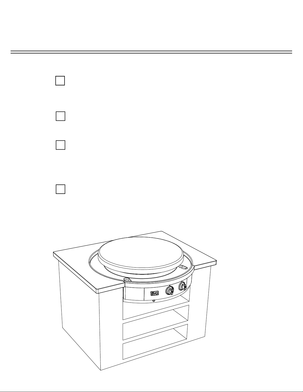
INSTALLATION AND USE CHECKLIST
UNPACK COOKTOP COMPONENTS 9
Follow unpacking instructions carefully
CLEARANCE TO COMBUSTIBLES DIMENSIONS 10
PREPARE COUNTER TOP FOR INSTALLATION 11-14
INSERT CHASSIS IN COUNTER TOP 15
INSTALL DRIP PAN AND DRIP PAN GASKET 16-17
ASSEMBLING COOK SURFACE RETAINING FASTENERS 18
INSTALL COOK SURFACE AND TIGHTEN FASTENERS 19-21
CONNECT GAS & CHECK FOR LEAKS 22-26
LOCATING THE GAS BURNERS ORIFICE JETS 27
CHECK LIST FOR INSTALLATION PROCEDURES 28
TEMPERATURE CONTROL AND LIGHTING INSTRUCITONS 29-30
RECOGNIZING ABNORMAL GAS OPERATION 31
REPLACING ELECTRONIC IGNITOR BATTERY 32
MAINTAINING SPILLOVER TRAYS 33
AFFINITY 30G DIMENSIONS 34
COOKING SURFACE MAINTENANCE 35
PAGE
INSTALLATION INSTRUCTIONS
A f f i n i t y 3 0 G
Evo, Inc., 20560 SW 115th Ave., Tualatin, OR 97062 USA
Phone 503.626.1802 | Fax 503.213.5869 | www.evoamerica.com | [email protected]
9
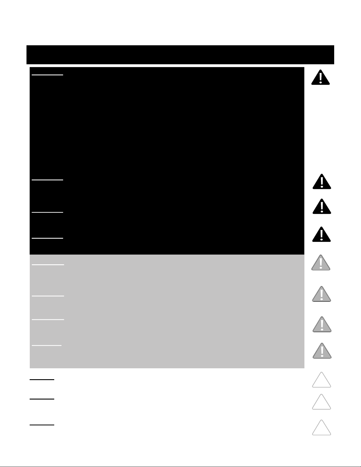
Cook Surface: Lift and separate cook surface from unit and place next to installation area.
Drip Pan Gasket:
Gasket is secured
to top of drip tray.
Remove gasket
from drip tray
and set aside
for reinstallation.
Drip Pan
Unlatch pan
from circular
skirt, then
carefully lift and
separate drip
pan from unit
and place next
to installation
area. Take care
not to scratch
drip pan during
installation.
Chassis:
Lift chassis
from crating box
and place on
its side next to
installation area.
Use caution
since ignition
components
are exposed.
Metal Right Angle Brackets: Unscrew from unit
and keep screws and brackets handy for fi rst
installation step.
UNPACKING COOKTOP COMPONENTS
STEP 1: As you are unpacking the crate, make sure you locate all components before
installation.
Ignition components are exposed during uncrating and installation.
Use caution and do not alter factory set positions.
The cook surface is heavy. Use caution when lifting.
Remove Tie
Down Bolts
and Tabs
holding chassis
to packing crate
base using 7/16”
wrench.
INSTALLATION INSTRUCTIONS
A f f i n i t y 3 0 G
Evo, Inc., 20560 SW 115th Ave., Tualatin, OR 97062 USA
Phone 503.626.1802 | Fax 503.213.5869 | www.evoamerica.com | [email protected]
10
CLEARANCE DIMENSIONS
Read the instructions carefully in this booklet to install the
Evo Affi nity 30G Cooktop to a metal, stone or wood counter top surface.
Cabinet layout and construction may vary.
CLEARANCE TO COMBUSTIBLE CONSTRUCTION FROM CHASSIS
Combustibles Non-combustibles
Back * 3/8” 0”
Sides * 3/8” 0”
Bottom 3” 3”
CLEARANCE TO COMBUSTIBLE CONSTRUCTION FROM COOKING SURFACE
Top 36”
Sides 12”
Back 12”
36” CLEARANCE FROM COOKING
SURFACE TO COMBUSTIBLE
CEILING MATERIALS.
12” CLEARANCE
FROM COOKING
SURFACE TO
COMBUSTIBLE
SIDEWALL
MATERIALS.
12” CLEARANCE
FROM COOKING
SURFACE TO
COMBUSTIBLE
BACK WALL
MATERIALS.
The minimum environmental temperature for safe use of the Evo Affi nity 30G
should not be below 32°F ( 0° C).
IF INSTALLING
ALONGSIDE
ANOTHER 30G
UNIT, PROVIDE
2” MINIMUM
CLEARANCE
FROM EDGE
OF DRIP PANS.
Minimum 3” clearance required under unit venting to 22 sq/in of combustible air.
* 3/8” of cement board lined enclosure to chassis.
INSTALLATION INSTRUCTIONS
A f f i n i t y 3 0 G
Evo, Inc., 20560 SW 115th Ave., Tualatin, OR 97062 USA
Phone 503.626.1802 | Fax 503.213.5869 | www.evoamerica.com | [email protected]
11
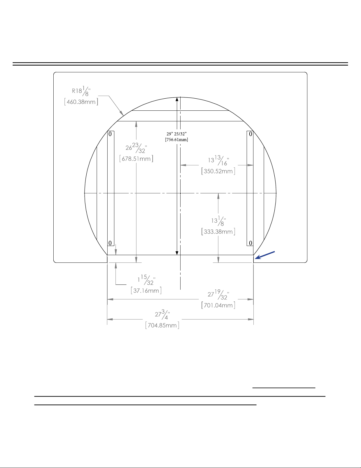
STEP 2: Mark the fi nished position of the Evo Affi nity 30G drip pan on the counter top using
the dimensions shown. The circular dimension of 36.25” is the diameter of the drip pan to the
outside material thickness (e.g. to the inside of the rolled bead edge). The drip pan cutout
must be made precisely to these dimensions (or at a maximum +1/16”) so that the half-rolled
top bead on the drip pan edge overhangs the cutout dimension by .25”.
(See following page for more details).
OPENING IN COUNTER TOP FRONT
Counter top
overhang to
cabinet front
TOP VIEW
COUNTER TOP INSTALLATION (1 of 4)
NOTE:
If the dimensions for the
counter top overhang and
counter top depth cutout
are not followed, there will
be a confl ict with the door
swing which allows access
to the waste containers.
INSTALLATION INSTRUCTIONS
A f f i n i t y 3 0 G
Evo, Inc., 20560 SW 115th Ave., Tualatin, OR 97062 USA
Phone 503.626.1802 | Fax 503.213.5869 | www.evoamerica.com | [email protected]
12
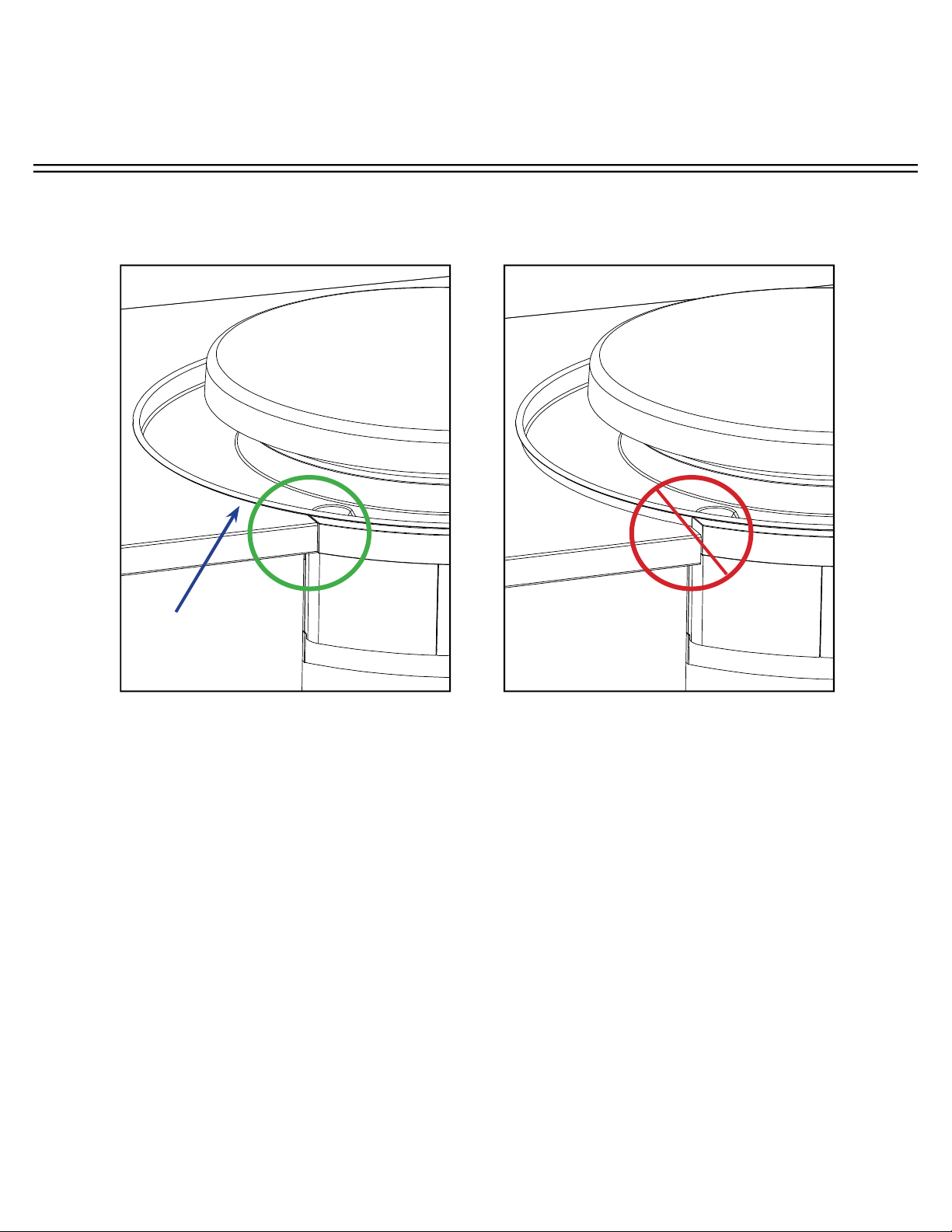
COUNTER TOP INSTALLATION (2 of 4)
STEP 2 continued: Make sure cabinetry box is 3cm (minimum) below counter top surface
and mounting brackets are positioned correctly so drip pan and chassis are aligned to
counter top(see diagrams above). A black o-ring is recessed in the top bead and designed to
create a seal against the counter top.
Also ensure allowance for the counter top overhang as shown on the SIDE VIEW (see next
page).
When you have confi rmed the position is correct, cut the counter top and substrate.
CORRECT ALIGNMENT OF DRIP PAN
AND CHASSIS TO COUNTERTOP
INCORRECT ALIGNMENT OF DRIP PAN
AND CHASSIS TO COUNTER TOP
Possible reasons for incorrect alignment:
1. Top of cabinetry box is less than 3 cm
from counter top
2. Chassis mounting brackets are too high.
Black o-ring under
drip pan bead
INSTALLATION INSTRUCTIONS
A f f i n i t y 3 0 G
Evo, Inc., 20560 SW 115th Ave., Tualatin, OR 97062 USA
Phone 503.626.1802 | Fax 503.213.5869 | www.evoamerica.com | [email protected]
13
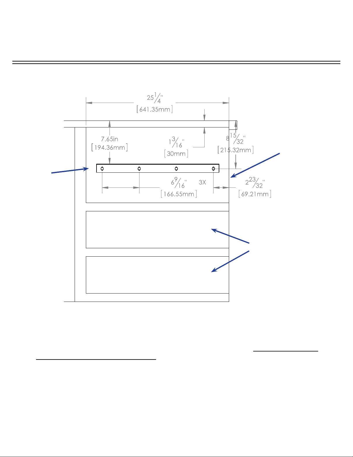
SIDE VIEW
Example of 3/8” tile with substrate for a minimum 3 cm (1-1/5”) overall. Make sure you allow
for the counter top overhang as shown.
Metal
Right Angle
Mounting
Brackets
(supplied)
Shelving or
drawers can
be installed
under Affi nity
30G if
desired.
Finished cabinet face
set back from fi nished
counter top front edge
COUNTER TOP INSTALLATION (3 of 4)
INSTALLATION INSTRUCTIONS
A f f i n i t y 3 0 G
Evo, Inc., 20560 SW 115th Ave., Tualatin, OR 97062 USA
Phone 503.626.1802 | Fax 503.213.5869 | www.evoamerica.com | [email protected]
14
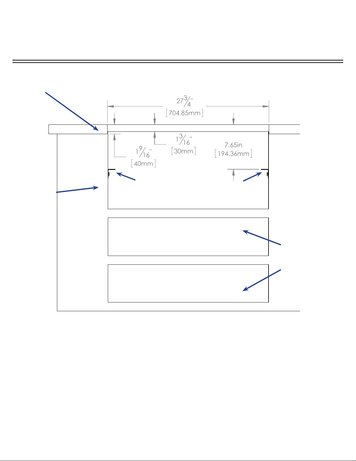
Shelving or
drawers can
be installed
under Affi nity
30G if
desired.
FRONT VIEW
STEP 3: Construct a bay for the Evo unit with your chosen cabinet system. Position and
fasten the supplied mounting brackets 7.65” below the fi nished counter top surface.
Metal right angle mounting brackets supplied with unit are
each 1/16” thick. Mount angle brackets as shown. Unit slides
into framework and rests on top side of brackets. Brackets
are slotted for fasteners at each four corners.
Cabinet
Framework
Example: Tiled counter top with substrate.
Finished counter top thickness should be
3 cm (1-1/5”).
COUNTER TOP INSTALLATION (4 of 4)
INSTALLATION INSTRUCTIONS
A f f i n i t y 3 0 G
Evo, Inc., 20560 SW 115th Ave., Tualatin, OR 97062 USA
Phone 503.626.1802 | Fax 503.213.5869 | www.evoamerica.com | [email protected]
15
STEP 4: Slide the Affi nity 30G chassis into the counter top so it rests on top of the installed
brackets. Bolt unit to angle brackets using supplied 1/4” x 20 fasteners from underside.
INSERT CHASSIS IN COUNTER TOP
Use supplied 1/4” fasteners to bolt
chassis to angle brackets.
Gas Installation must be done by a licensed professional in accordance with
local guidelines once unit has been completely installed. Refer to pages 22-
26 for further instructions.
INSTALLATION INSTRUCTIONS
A f f i n i t y 3 0 G
Evo, Inc., 20560 SW 115th Ave., Tualatin, OR 97062 USA
Phone 503.626.1802 | Fax 503.213.5869 | www.evoamerica.com | [email protected]
16
STEP 5: Slide drip tray over chassis circular skirt positioning spillover slots to the
corresponding slots of the top chassis deck. Notice the drip pan catches showing through the
inside cutout locations of the circular chassis skirt. From the inside of the skirt, use each of
the three latches to pull the drip pan down into the counter.
Drip Tray
Catches
DRIP PAN INSTALLATION
GRILL FRONT
INSTALLATION INSTRUCTIONS
A f f i n i t y 3 0 G
Evo, Inc., 20560 SW 115th Ave., Tualatin, OR 97062 USA
Phone 503.626.1802 | Fax 503.213.5869 | www.evoamerica.com | [email protected]
17
STEP 6: Secure drip pan to chassis using access slot (A). Rewrap drip pan gasket around
top of drip tray and secure (B). Ensure seal under drip pan edge is touching counter top(C).
Drip pan gasket
seam at rear
DRIP PAN AND GASKET INSTALLATION
CROSS SECTION OF
CHASSIS ACCESS SLOT
Hook drip pan latch under
chassis catch and tighten
screw at chassis access slot.
A
Slip gasket ring onto top of
drip pan so it creates a seal to
the chassis skirt.
CROSS SECTION OF
DRIP PAN TOP
CROSS SECTION OF
DRIP PAN EDGE
Ensure the black seal under
the drip pan bead edge is
touching the counter top.
B C
Drip
Pan
Counter
top
Drip
Pan
Chassis
skirt
Use No. 3 Phillips screwdriver to
secure drip pan
at the access points.
INSTALLATION INSTRUCTIONS
A f f i n i t y 3 0 G
Evo, Inc., 20560 SW 115th Ave., Tualatin, OR 97062 USA
Phone 503.626.1802 | Fax 503.213.5869 | www.evoamerica.com | [email protected]
18
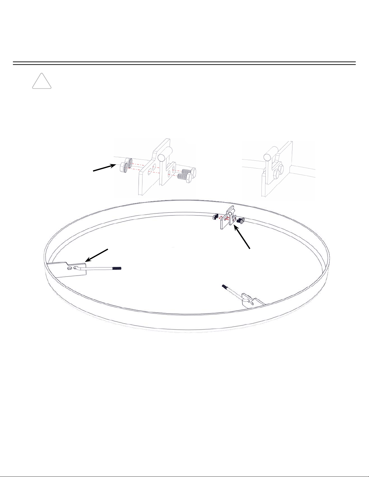
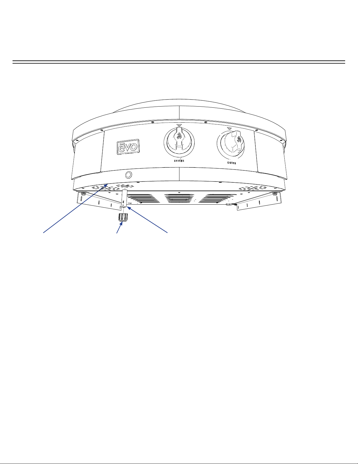
STEP 7: Locate Parts Box shipped with your Affi nity 30G and the parts bag containing the
Rear Retaining Bullet Fastener, two each 1/4” x 20 hex bolt and locking nut, and two each
J-Hook. Follow the illustration show on this page, and using a 7/16” wrench tighten the Rear
Retaining Bullet to a cook surface tab as shown (Ensure the Rear Retaining Bullet is placed
on the right hand side of the tab). Next, loop the J-Hook through the inside slot of each
remaining tab.
ASSEMBLING COOK SURFACE RETAINING FASTENERS
IT IS RECOMMENDED THE COOKING SURFACE BE PLACED ON A PROTECTED
WORK SURFACE WITH THE FLANGE FACING UPWARD.
Place Rear Retaining
Bullet Fastener on right
hand side of tab.
Using a 7/16” wrench,
tighten the Rear
Retaining Bullet to the
cooking surface tab with
two each 1/4” x 20 hex
bolt and locking nut.
Ensure the bolts are
tightened securely.
Loop the J-Hook
through the inside slot
of two tabs as shown.
INSTALLATION INSTRUCTIONS
A f f i n i t y 3 0 G
Evo, Inc., 20560 SW 115th Ave., Tualatin, OR 97062 USA
Phone 503.626.1802 | Fax 503.213.5869 | www.evoamerica.com | [email protected]
19
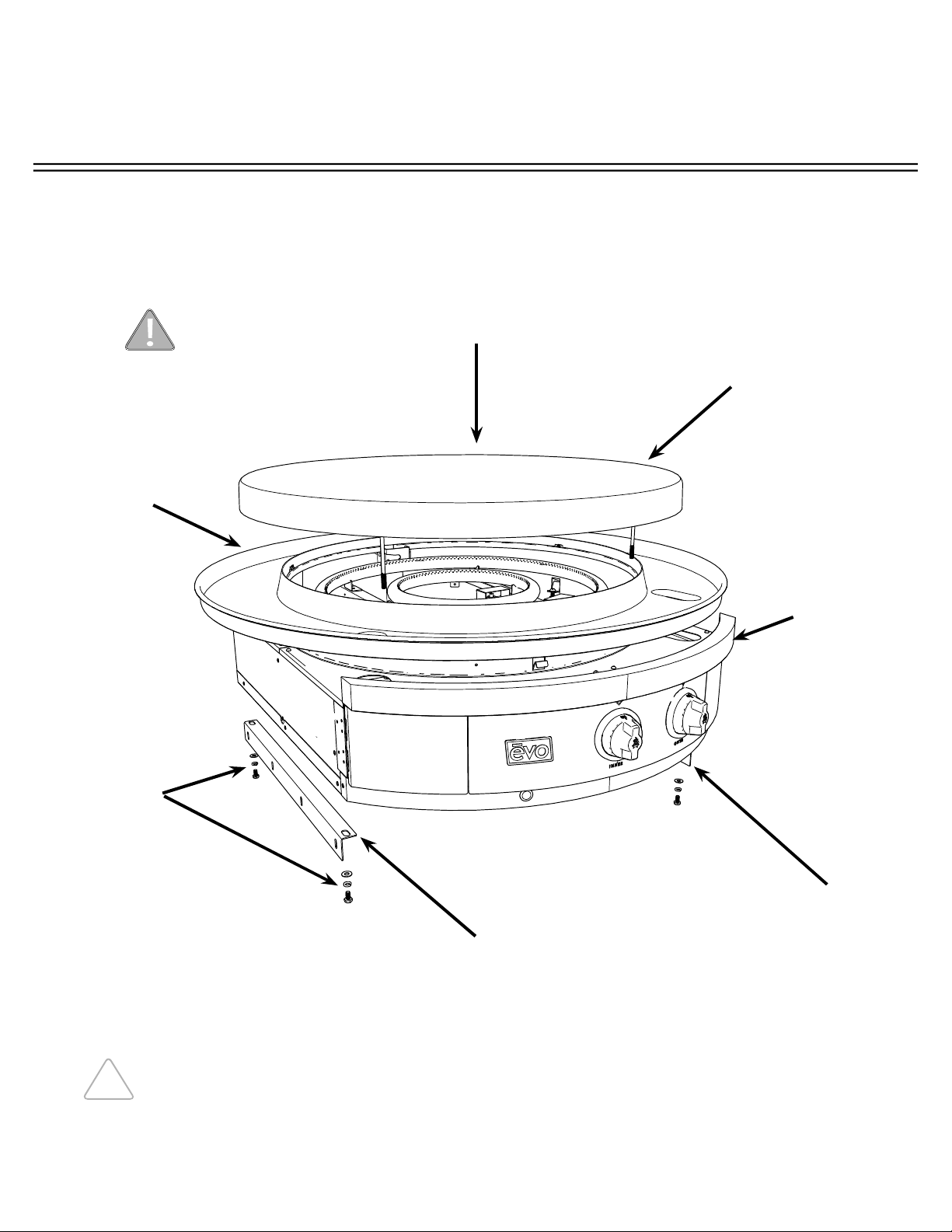
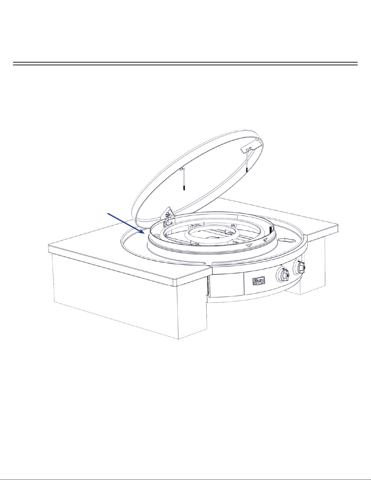
STEP 8: Position the cook surface at the rear of the burner chassis by placing the cook
surface in the area of the drip pan, separated by a towel or cardboard to prevent damage to
the drip pan.
CONNECTING COOK SURFACE
Place suitable protection on
drip pan (towel or cardboard).
Place cook surface vertically
with Bullet Fastener facing
downward.
INSTALLATION INSTRUCTIONS
A f f i n i t y 3 0 G
Evo, Inc., 20560 SW 115th Ave., Tualatin, OR 97062 USA
Phone 503.626.1802 | Fax 503.213.5869 | www.evoamerica.com | [email protected]
20
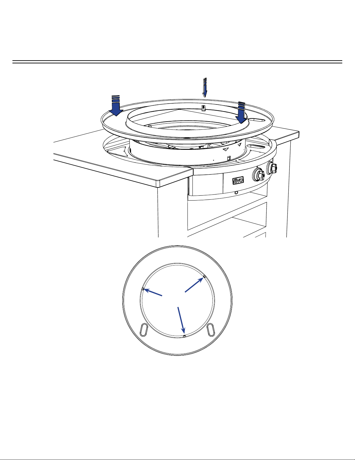
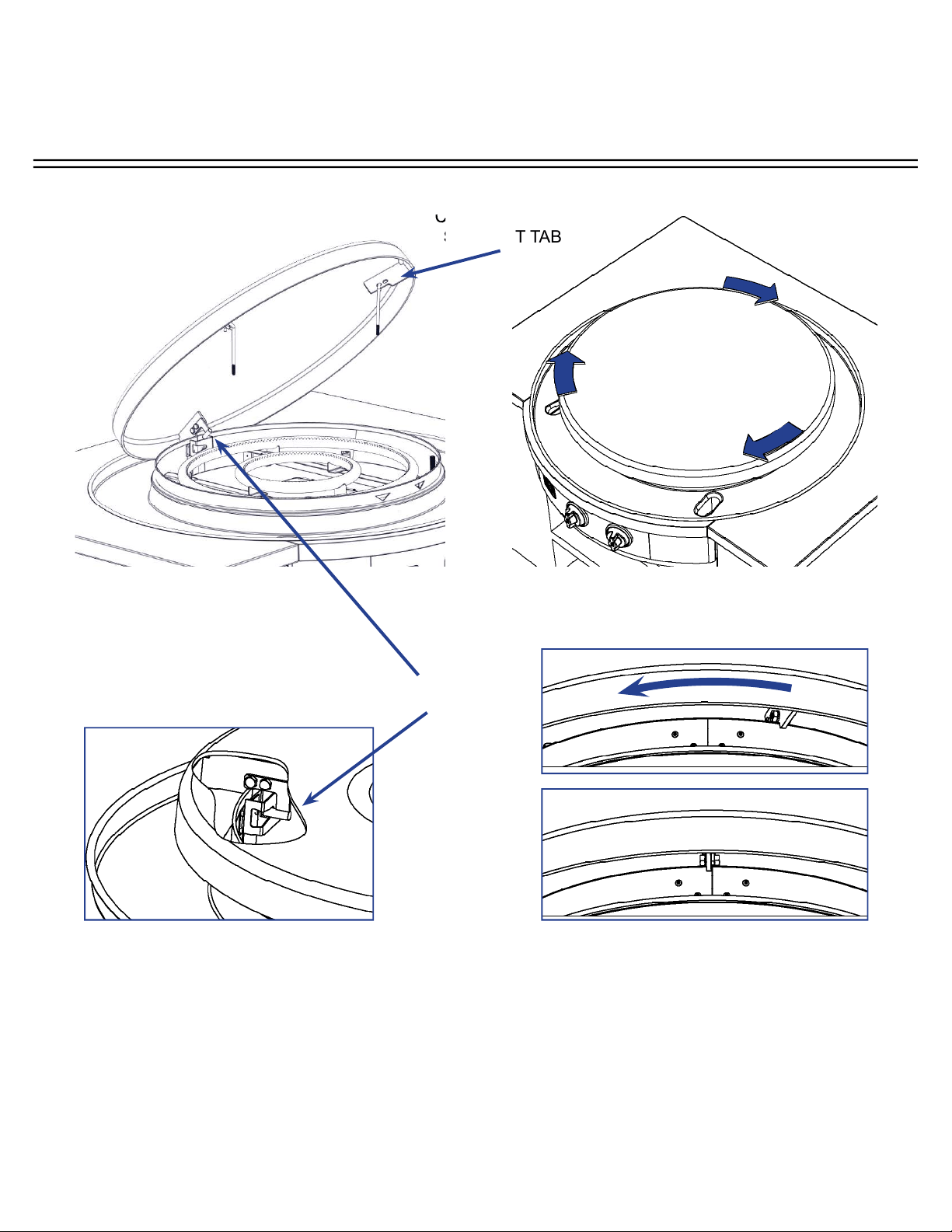
STEP 9: Place cook surface over circular skirt with the three support tabs (located under
cook surface) resting on the chassis skirt top. Position the rear support tab of the cook
surface to the right of the rear seam (rear view) of the chassis skirt (A). Then rotate the cook
surface clockwise until the support tab is in line with the seam (B) and the rear bullet secures
in the chassis slot (C).
COOK SURFACE
SUPPORT TAB
INSTALLING COOK SURFACE
BOTTOM-UP VIEW OF
REAR COOK SURFACE
CUT AWAY VIEW OF REAR COOK
SURFACE SHOWING BULLET
ENGAGED IN CHASSIS SLOT
A
B
C
REAR BULLET
INSTALLATION INSTRUCTIONS
A f f i n i t y 3 0 G
Evo, Inc., 20560 SW 115th Ave., Tualatin, OR 97062 USA
Phone 503.626.1802 | Fax 503.213.5869 | www.evoamerica.com | [email protected]
21
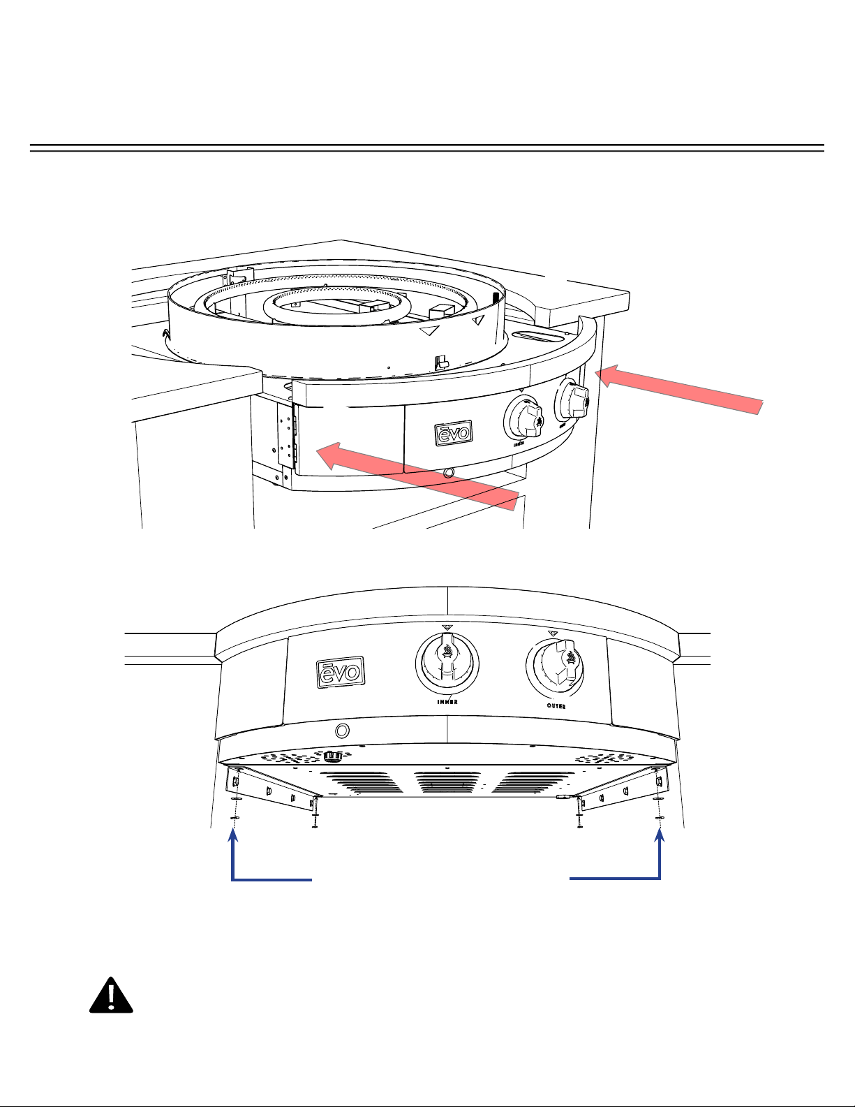
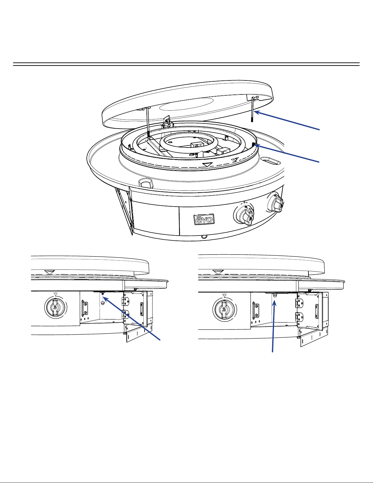
INSTALLING COOK SURFACE
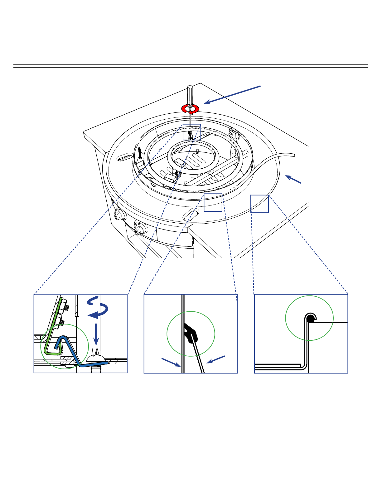
STEP 10: Locate two (2) J-hooks attached to underside of cooktop, cut zip ties and remove
nyloc nut.
One at a time, slide J-hooks through guide tubes. Slowly place cooktop down. Open both
waste doors and tighten nyloc nut on end of J-hook located at inside rear of each waste door.
Open waste
doors to locate
end of J-hook.
Guide Tube
J-Hook
Tighten nyloc nut
at end of each
J-hook.
INSTALLATION INSTRUCTIONS
A f f i n i t y 3 0 G
Evo, Inc., 20560 SW 115th Ave., Tualatin, OR 97062 USA
Phone 503.626.1802 | Fax 503.213.5869 | www.evoamerica.com | [email protected]
22
GAS SUPPLY
1/2 FNPT
Step 11: Connect Gas using stainless steel fl exible hose coupling supplied to outside gas
service. All Affi nity gas grills ship pre-confi gured for Natural Gas (NG) service unless otherwise
indicated on the Safety Label mounted to the right inside spillover drawer. If confi gured for
Natural Gas, the inlet pressure is at 7” Water Column (Fixed). If confi gured for LP Propane, the
inlet pressure is at 11” Water Column (Fixed).
Refer to pages 22-26 for specifi c instructions regarding LP and NG connections, checking for
gas leaks and recognizing abnormal gas operation (page 31).
CONNECTING GAS
FOR YOUR PROTECTION, WE RECOMMEND A QUALIFIED GAS TECHNICIAN
INSTALL THIS COOKTOP. THIS PERSON SHOULD BE FAMILIAR WITH GAS
SERVICE INSTALLATIONS AND ALL LOCAL CODES. PROPER CONNECTIONS
ARE ESSENTIAL FOR EFFICIENT OPERATION AND SAFETY.
INSTALLATION INSTRUCTIONS
A f f i n i t y 3 0 G
Evo, Inc., 20560 SW 115th Ave., Tualatin, OR 97062 USA
Phone 503.626.1802 | Fax 503.213.5869 | www.evoamerica.com | [email protected]
23
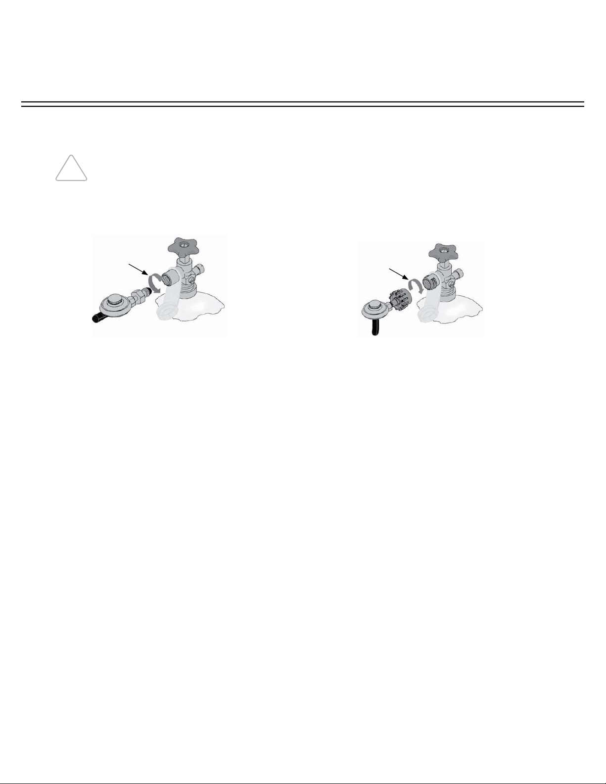
CONNECTING GAS - LP CYLINDER CONNECTION
Standard POL Regulator Install
Figure 1
Gas LP Cylinder
Regulator
& Hose
Gas Shutoff Valve
Tighten This Direction
Protective
Cap
Figure 2
Quick Disconnect Hand-Wheel Regulator Install
Gas LP Cylinder
Gas Shutoff Valve
Regulator
& Hose
Tighten This Direction
Protective
Cap
Note: Cylinder Collar removed from these illustrations for clarity
1. Be sure both cooktop burner valves are in the Off position.
2. Make sure the gas tank valve is off and in the closed position by turning clockwise (left to
right) to a full stop.
3. Remove the protective cap from the gas cylinder valve.
4. Hold the supplied regulator in one hand and position the plastic coupling nut on the cylinder
valve outlet threads using care to engage the center of the coupling nut to the center of the
cylinder valve outlet. When completing this procedure, take care to not cross-thread the
connection.
5. Observe the direction in Figure 1 and Figure 2 for installing the regulator threads to the
cylinder valve. For a Standard POL Regulator turn the coupling nut counterclockwise (right
to left) and tighten to a full stop. For the Quick Disconnect Regulator turn the coupling nut
clockwise (left to right) and tighten to a full stop.
In the connection process, the regulator will seal on the back-check feature in the cylinder
valve resulting in a slight resistance. The connection requires about a 1/2 to 3/4 additional turn
to complete the connection. Tighten by hand only - do not use tools. If you cannot make the
connection, disconnect the regulator and repeat steps 4 and 5.
If the unit is not in use, gas must be turned off at the supply cylinder. Inspect hoses before
each use of the unit. If it is evident there is excessive abrasion or wear, or the hose is cut,
it must be replaced prior to the unit being put into operation. Regulator and hose assembly
can be purchased from Evo by calling 866-626-1802 or from a local gas supply company.
Specifi cations for these parts are:
• LP Regulator: 90 degree w/ 3/8” Female SAE Inlet
• LP Hose: 60” Type #1 Low Pressure
Use the pressure regulator and hose assembly supplied with your Evo cooktop.
Recommended LP propane cylinder is a standard 5 gallon, 20 Lb., with a shutoff
valve terminating in a cylinder valve outlet specifi ed and an (OPD) overfl ow
prevention device valve, compliant to current DOT specifi cations. If the cylinder is
fi tted with a Type I Cylinder Connection Device, a protective dust cap must be installed
on the valve outlet.
INSTALLATION INSTRUCTIONS
A f f i n i t y 3 0 G
Evo, Inc., 20560 SW 115th Ave., Tualatin, OR 97062 USA
Phone 503.626.1802 | Fax 503.213.5869 | www.evoamerica.com | [email protected]
24
STORAGE & REMOVAL OF LP GAS CYLINDER:
Never store LP gas cylinder indoors. When cooktop is stored indoors, shut cylinder
valve off and disconnect cylinder from grill and remove to an outdoor location. Cylinder
must be stored outdoors in well-ventilated area, away from and out of the reach of
children. Cylinder should not be allowed to remain in a high heat area such as a closed
car, trunk, or in direct sunlight.
Loosen coupling nut located on regulator and cylinder valve by turning counterclockwise using
hands only - do not use tools. Next loosen thumb screws securing cylinder to lower rack and
remove tank. Install safety cap over cylinder valve coupling.
Do not store spare LP gas cylinder under or near this appliance. Never fi ll cylinder
beyond 80% full. Cylinder must be constructed and marked in accordance with the
specifi cations for propane cylinders of the U.S. Department of Transportation (DOT), or
CAN/CSA B339. If the above information is not followed exactly, a fi re causing death or
serious injury may occur.
WARNING
STORAGE, REMOVAL and TRANSPORTATION OF LP CYLINDER
TRANSPORTATION OF LP CYLINDER:
Never remove or alter cylinder labeling. Labels contain critical information on the safe handling
of gas products. The DOT requires that proper labeling must be in place before the products
can be off ered for transportation.
Transporting cylinders in cars, vans, or in any enclosed vehicle is extremely dangerous, and
should be avoided. Never transport fl ammable gases in the trunk or passenger compartment of
a vehicle.
Always install the protective cap on the cylinders when they are being transported, or any
time they are not in use. If the cylinders were not designed to accept a protective cap over
the valve, special care must be taken to prevent the valve from damage or opening during
transportation.
Secure your cylinders. The Department of Transportation (DOT) regulations require that all
compressed gas cylinders be secured from movement during transportation. Cylinders that can
move can open accidentally, or roll off the vehicle into the path of oncoming traffi c.
Handling, storage and transportation of all gas cylinders must be in accordance with ANSI/
NFPA 58, Storage and Handling of Liquid Petroleum Gases, or CSA B149.1, Natural Gas and
Propane Installation Code.
INSTALLATION INSTRUCTIONS
A f f i n i t y 3 0 G
Evo, Inc., 20560 SW 115th Ave., Tualatin, OR 97062 USA
Phone 503.626.1802 | Fax 503.213.5869 | www.evoamerica.com | [email protected]
25
CHECKING GAS LEAKS (LP)
Do not ignite burners or use an open fl ame to check for gas leaks. Be sure there are no sparks
or open fl ames in the area while you check for gas leaks. Flames and sparks will result in a fi re
or explosion which can cause serious bodily injury or death and damage to property.
DANGER
Note: All factory-made connections have been thoroughly checked for gas leaks.
The burners and ignition system has been fl ame tested. As a safety precaution, we
recommend you recheck all fi ttings for leaks before using your Evo grill. Shipping and
handling may loosen or damage a gas fi tting.
To perform a leak check you will need a solution of soap and water and a brush or rag to
wet all gas connections.
1. Turn all control knobs to the OFF position.
2. Turn on gas supply and check for leaks by wetting the connections with the soap and water
solution and watching for bubbles. If bubbles appear, or if a bubble grows, there is a leak.
Note: Since some leak test solutions, including soap and water, may be slightly
corrosive, all connections should be rinsed with water after checking for leaks.
WARNING
Perform leak checks even if your grill was
dealer or store assembled.
You should check for gas leaks every time
you disconnect and reconnect a gas fi tting.
WARNING
CHECK ALL GAS CONNECTIONS:
1. Hose to Regulator.
2. Regulator to Gas Supply connection.
PLEASE POST THESE INSTRUCTIONS IN A PROMINENT LOCATION
INSTALLATION INSTRUCTIONS
A f f i n i t y 3 0 G
Evo, Inc., 20560 SW 115th Ave., Tualatin, OR 97062 USA
Phone 503.626.1802 | Fax 503.213.5869 | www.evoamerica.com | [email protected]
26
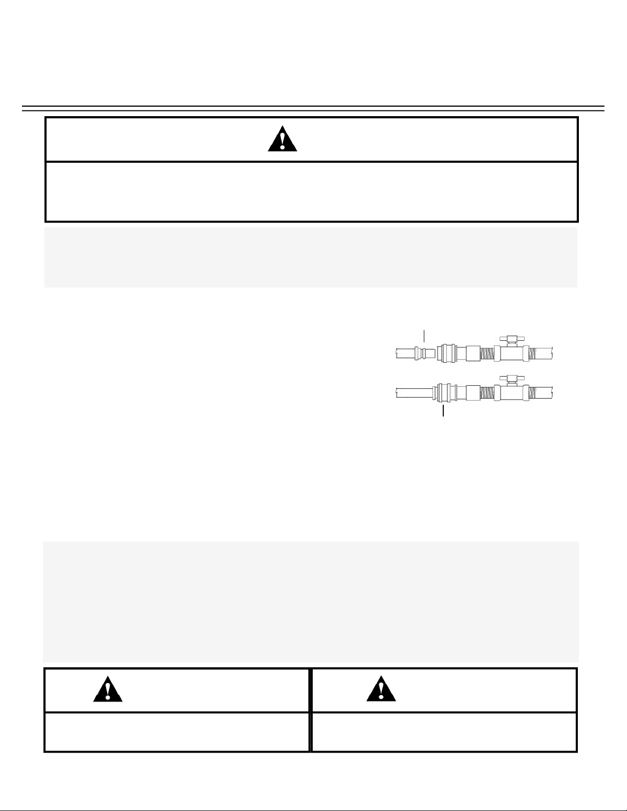
Gas Coupling Connected
Gas Coupling Disconnected
CHECKING GAS LEAKS (NATURAL GAS)
Do not ignite burners or use an open fl ame to check for gas leaks. Be sure there are no sparks
or open fl ames in the area while you check for gas leaks. Flames and sparks will result in a fi re
or explosion which can cause serious bodily injury or death and damage to property.
DANGER
Note: All factory-made connections have been thoroughly checked for gas leaks. The
burners and ignition system has been fl ame tested. As a safety precaution, we recommend
you recheck all fi ttings for leaks before using your Evo cooktop. Shipping and handling
may loosen or damage a gas fi tting.
To perform a leak check you will need a solution of soap and water and a brush or rag to
wet all gas connections.
1. Turn all control knobs to the OFF position.
2. Slide back the collar of the quick disconnect. Push the
male fi tting of the hose into the quick disconnect and
maintain pressure while releasing the collar.
3. If fi tting does not engage and lock, repeat procedure.
Gas will not fl ow unless the quick disconnect is properly
engaged.
4. Turn on gas supply and check for leaks by wetting the connections with the soap and water
solution and watching for bubbles. If bubbles appear, or if a bubble grows, there is a leak.
Note: Since some leak test solutions, including soap and water, may be slightly corrosive,
all connections should be rinsed with water after checking for leaks.
CHECK ALL GAS CONNECTIONS:
1. Hose to Manifold Connection.
Warning: If there is a leak where the hose connects to the manifold then retighten the fi tting with a wrench
and recheck for leaks with soap and water. If leak continues after retightening the fi tting, tun off gas. DO NOT
OPERATE COOKTOP. Contact your local dealer or Evo Customer Service using the contact information provided
with your manual.
2. Valves to Manifold Connections.
3. Hose to Quick Disconnect Connection.
WARNING
Perform leak checks even if your cooktop
was dealer or store assembled.
You should check for gas leaks every time
you disconnect and reconnect a gas fi tting.
WARNING
PLEASE POST THESE INSTRUCTIONS IN A PROMINENT LOCATION
INSTALLATION INSTRUCTIONS
A f f i n i t y 3 0 G
Evo, Inc., 20560 SW 115th Ave., Tualatin, OR 97062 USA
Phone 503.626.1802 | Fax 503.213.5869 | www.evoamerica.com | [email protected]
27
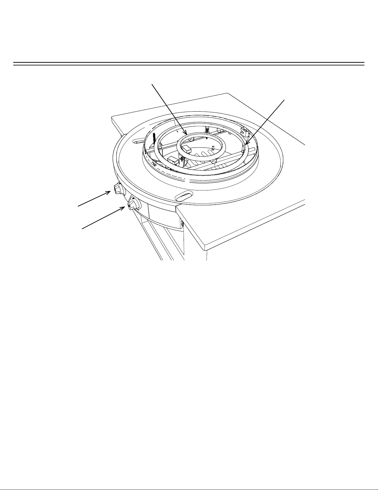
LOCATING THE GAS BURNERS AND ORIFICE JETS
PLEASE POST THESE INSTRUCTIONS IN A PROMINENT LOCATION
1. The Affi nity 30G Gas Tube Burners are located under the cooking surface and inside the
stainless steel Burner Skirt. They are arranged with the smaller inner burner located in the
center of the burner skirt and the larger outer burner located outside the inner burner.
2. The Gas Burner Orifi ce Jets for the inner and outer burners are located directly below the
circular tube burners and are positioned just inside the Burner Venturi as illustrated below.
To remove an orifi ce, pull the Orifi ce Retaining Arm away from the orifi ce and then move the
orifi ce from the venturi.
Orifi ce Retaining Arm
Gas Burner Orifi ce
Inner Burner
Outer Burner
INSTALLATION INSTRUCTIONS
A f f i n i t y 3 0 G
Evo, Inc., 20560 SW 115th Ave., Tualatin, OR 97062 USA
Phone 503.626.1802 | Fax 503.213.5869 | www.evoamerica.com | [email protected]
28
CHECK INSTALLATION
DRIP PAN PROPERLY INSTALLED 16
Ensure that the drip pan half-rolled top bead overhangs
the cutout dimension by .25” and the black o-ring
is creating a seal against the counter top.
DRIP PAN GASKET SECURED 17
Black drip pan gasket should fi t properly and create a
seal where the drip pan meets the chassis skirt.
COOK SURFACE INSTALLED PROPERLY 18-21
Cook surface support rails should be sitting on
chassis top with rear bullet secure in rear slot and
two front fasteners tightened so cook surface does
not move.
GAS CONNECTION HOOKED UP PROPERLY 22-27
Check for gas leaks.
Check for proper operation.
PAGE
Check to ensure the following items are complete:
OPERATOR INSTRUCTIONS
A f f i n i t y 3 0 G
Evo, Inc., 20560 SW 115th Ave., Tualatin, OR 97062 USA
Phone 503.626.1802 | Fax 503.213.5869 | www.evoamerica.com | [email protected]
29
Outer Burner
Control Knob
Inner Burner
Control Knob
Inner Burner
Outer Burner
EVO AFFINITY 30G TEMPERATURE CONTROL
Inner Burner and Inner Control Knob - The Inner Burner is a 10” diameter gas fi red burner operating
at 24,000BTU’s. This burner is controlled by the Inner or center-most control knob. Temperatures are
adjustable from 225F° to 550F°. Starting at the Off position, the Inner Control Knob rotates 180-degrees
counterclockwise through three positions.
Outer Burner and Outer Control Knob - The Outer Burner is a 20” diameter gas fi red burner operating
at 24,000BTU’s. This burner is controlled by the Outer or outer-most control knob. Temperatures are
adjustable from 225°F to 550°F. Starting at the Off position, the Outer Control Knob rotates 180-degrees
counterclockwise through three positions.
Either the Inner or the Outer burners may be used independently to support a wide range of cooking
techniques. Operating only the Inner burner provides direct temperature under the center of the cook
surface, with indirect heat at the outside edge that is useful for holding pre and post cooking processes.
Conversely only the Outer burner can be used for cooking foods that may be displayed around the
outside radius of the grill. Finally, both burners can be used together for maximum surface temperature
and cooking versatility.
Because the burners are enclosed within a circular chassis and all heat is directed upward at the cook
surface, cook surface temperature recovery is nearly immediate, providing a wide range of surface
temperature adjustment and control.
OPERATOR INSTRUCTIONS
A f f i n i t y 3 0 G
Evo, Inc., 20560 SW 115th Ave., Tualatin, OR 97062 USA
Phone 503.626.1802 | Fax 503.213.5869 | www.evoamerica.com | [email protected]
30
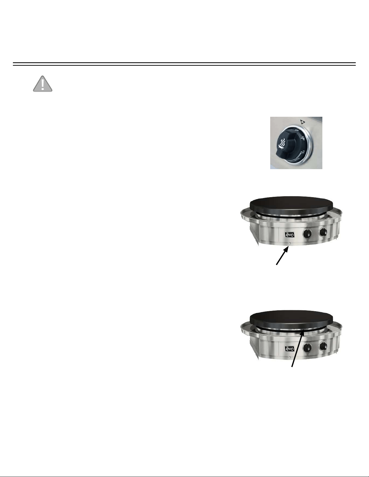
LIGHTING INSTRUCTIONS
Electronic Ignitor Lighting Procedure:
1. Read instructions carefully before lighting.
2. Cooking surface must be in place and secure before
lighting.
3. Hold down the igniter button, then turn the Control
Knob to ‘Lite’. View the fl ame through the viewing
holes in the Grill body to confi rm it is lit. If the burner is
lit, turn the knob to ‘the desired setting to commence
cooking.
4. If ignition does not occur in 5 seconds release igniter,
turn the burner Control Knob off , wait 5 minutes, and
repeat lighting instructions.
If after the repeated attempt the burner does not ignite,
follow the manual lighting procedure below.
Manual Lighting Procedure:
1. To light the burner manually, feed a lit match through
one of the fl ame viewing holes in the burner skirt
above the control panel until it is close to the burner.
2. Turn the Control Knob to the ‘Lite’ position. View the
fl ame through the opposite viewing hole in the grill
body to confi rm it is lit. If the burner is lit, turn the knob
to the desired setting to commence cooking.
3. Once the burner has been lit, remove the match and
extinguish the match fl ame.
Control Knob
Match
BEFORE EACH USE: Inspect gas hose under unit. If it is evident there is excessive
abrasion or wear, or the hose is cut, please contact Evo for a replacement hose.
Igniter Button
OPERATOR INSTRUCTIONS
A f f i n i t y 3 0 G
Evo, Inc., 20560 SW 115th Ave., Tualatin, OR 97062 USA
Phone 503.626.1802 | Fax 503.213.5869 | www.evoamerica.com | [email protected]
31
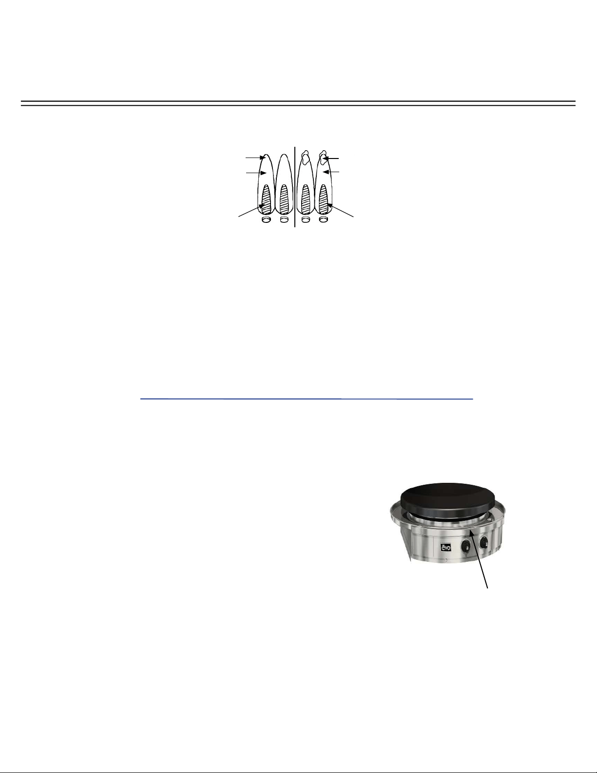
RECOGNIZING ABNORMAL GAS OPERATION
Any of the following are considered to be abnormal operation and may require servicing:
• Excessive yellow tipping of the burner fl ame (See diagram above).
• Sooting up of cooking utensils.
• Burners not igniting properly.
• Burners failing to remain alight.
• Gas valves, which are diffi cult to turn.
In case the appliance fails to operate correctly, contact the authorized service provider in your
area.
Right
Flame
Wrong
Flame
Dark BlueDark Blue
Light Blue Light Blue
Yellow Tip
Excessive
Yellow Tipping
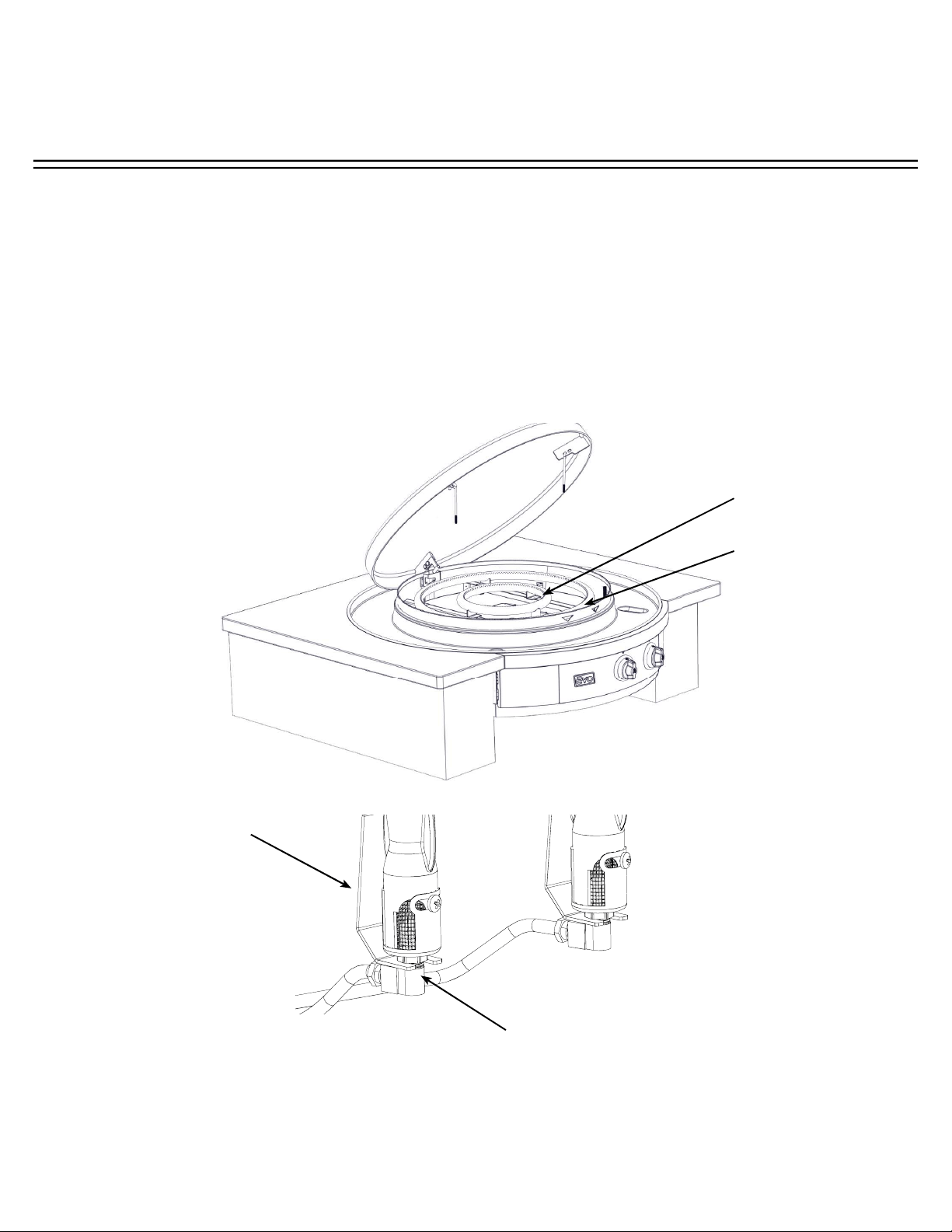
Remove cooking surface
and drip pan to access valve
cover located just above
center control knob and
under the drip pan.
Checking Venturi Tubes:
A clogged venturi tube due to insects and insect nests in
the venturi tube may cause improper burner performance
and diffi culty lighting your grill.
To check your venturi tubes:
• Remove the cooking surface and drip pan to access the
valve cover located just above the center control knob
and under the drip pan.
• Remove the cover and inspect the venturi for insects
and or insect nests.
• Compressed air is the best method for removing these
obstructions.
OPERATOR INSTRUCTIONS
A f f i n i t y 3 0 G
Evo, Inc., 20560 SW 115th Ave., Tualatin, OR 97062 USA
Phone 503.626.1802 | Fax 503.213.5869 | www.evoamerica.com | [email protected]
32
REPLACING ELECTRONIC IGNITOR BATTERY
If the ignitor does not work, you may need to replace the battery.
1. Look under the front control panel just below the ignitor button (A).
2. Remove the ignitor cap, rotating it counterclockwise (B).
3. Install a AA type battery into the ignitor housing with the positive “+” end facing downward (C).
4. If the ignitor is still not working, contact Evo Customer Support for an ignitor replacement.
Remove and replace
AA type battery with
+ positive end facing
downward.
B C
A
Remove ignitor
battery cap to
remove battery.
Look under front
control panel to
fi nd ignitor battery
compartment.
OPERATOR INSTRUCTIONS
A f f i n i t y 3 0 G
Evo, Inc., 20560 SW 115th Ave., Tualatin, OR 97062 USA
Phone 503.626.1802 | Fax 503.213.5869 | www.evoamerica.com | [email protected]
33
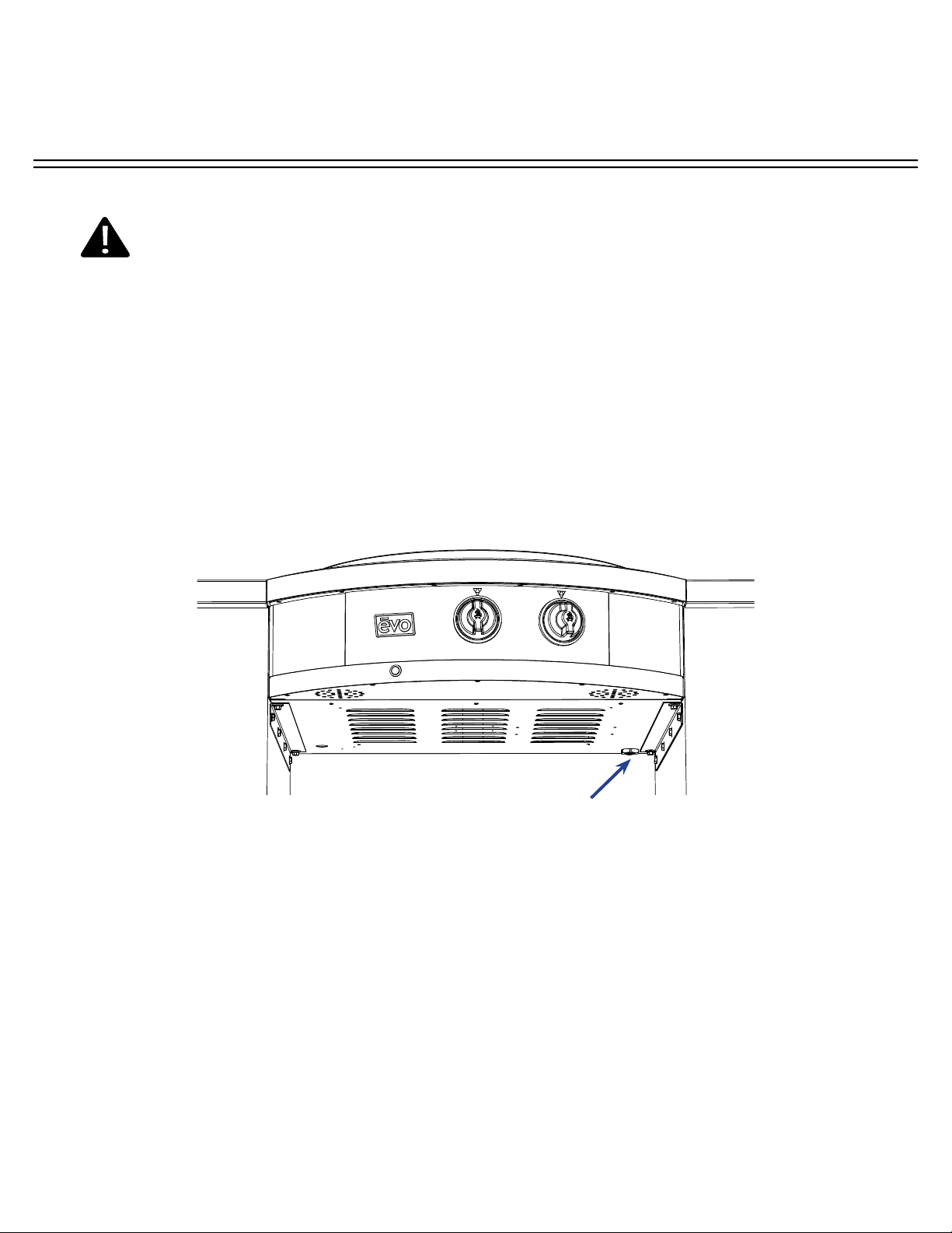
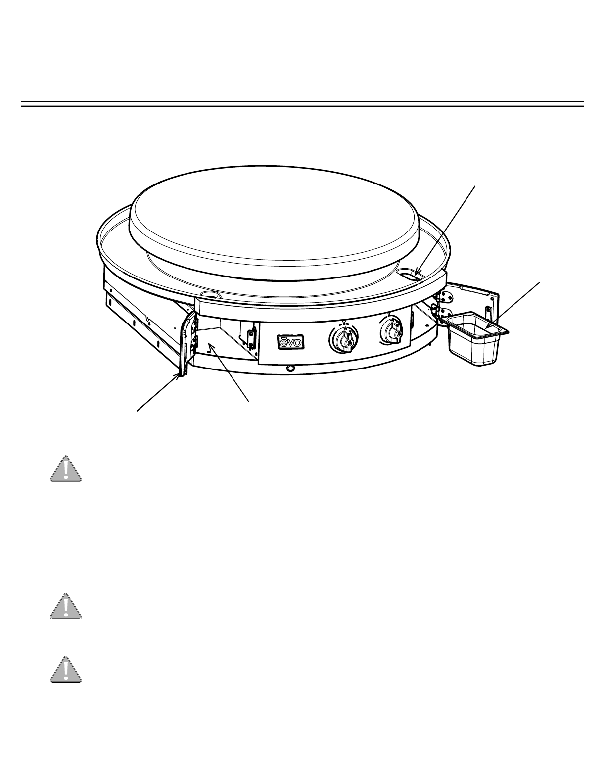
The Affi nity grill has removable waste pans concealed in doors on both the right and left side of the front control panel.
It is very important to monitor the level of spillover in the trays, and immediately empty when they are near full or after
each use.
Opening Spillover Tray Doors - To open a door, grasp the door at its bottom and pull forward.
Do not operate cook top or clean drip pan into spillover slots without waste pans installed in
spillover doors. Failure to install waste pan will result in cooking grease contamination to the
underside of door. This requires immediate cleaning.
Do not allow spillover liquids or debris down spillover slots when doors are open. Any liquids or
debris that may fall into this area when doors are open should be immediately wiped with a dry
cloth, and keep this area clean at all times.
Do not allow the spillover trays to overfl ow, and do not allow full trays to splash over edge when
cleaning. Spillover debris and liquids can be hot and cause burns, and/or damage to the internal
operation of the grill.
REMOVABLE SPILLOVER TRAYS
Removable waste pan
Access
Door
Spillover Slot
Insert each waste pan all the way to the
back of the left and right compartments.
OPERATOR INSTRUCTIONS
A f f i n i t y 3 0 G
Evo, Inc., 20560 SW 115th Ave., Tualatin, OR 97062 USA
Phone 503.626.1802 | Fax 503.213.5869 | www.evoamerica.com | [email protected]
34
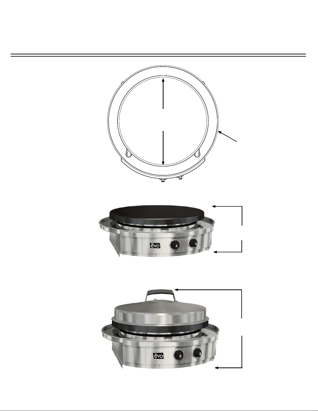
36 1/8”
914mm
30”
762mm
Diameter
11 1/4””
292mm
21 1/4”
495mm
AFFINITY 30G DIMENSIONS

OPERATOR INSTRUCTIONS
A f f i n i t y 3 0 G
Evo, Inc., 20560 SW 115th Ave., Tualatin, OR 97062 USA
Phone 503.626.1802 | Fax 503.213.5869 | www.evoamerica.com | [email protected]
35
Regular cleaning and care for your Evo Affi nity 30G cooktop will keep it looking and functioning its best.
The cook surface is designed to hold a fi ne layer of cooking oil creating a ‘seasoning’ on its surface. This
seasoning promotes a non-stick cooking surface and is easily maintained.
Caring for Evo’s cook surface is much like maintaining cast iron cookware. When the surface requires cleaning,
there are a few basic cleaning techniques to use. For quick and routine cleaning between preparations, a metal
spatula or scraper works for removing the majority of surface debris. For tougher areas or where sugars glaze the
cook surface, pour a small amount of cooking oil on the soiled surface while the grill is warm and scrape the debris
away with a spatula. Heat the cook surface to a high temperature and allow the sticky debris to become brittle.
Once the debris is brittle, use the spatula or scraper to remove it. Afterwards wipe the cook surface with vegetable
oil again before cooking.
To condition the Evo cook surface you should use the grill cleaning kit supplied with your grill. The grill cleaning kit
contains a blue grill pad handle, grill cleaning screens, and grill grey polishing pads. Use the polishing pad after
the grill cleaning pads to achieve a smooth cooking surface for the most delicate foods and applications.
To use a grill cleaning screen: With a warm cook surface, place one gray polishing pad between the grill handle
base and the grill screen, so the grill screen makes direct contact with the cooking surface. Pour a small amount
of vegetable oil on the cook surface and scrub the surface in a circular motion. The gray polishing pad allows
excess oil to be absorbed and scours the cooking surface of carbonized debris. When fi nished scrubbing, wipe
the surface down with a paper towel or cotton terry cloth.
The drip pan located just below the cook surface is designed to catch food debris and drippings from the cook
surface. We recommend cleaning the drip pan after your grill has cooled to prevent the possibility of touching
hot adjoining surfaces. The drip pan is easy to wipe out with soap and water using a kitchen sponge. For added
convenience, two removable stainless ninth-pans are mounted inside retractable drawers at right and left side of
the front control panel for collecting drip pan debris and spill overs. These spillover trays can be easily washed by
hand or in a dishwasher. Be sure to empty the spillover trays after every use, and at a minimum, whenever they
appear half full.
All the stainless steel components on your grill can be easily polished using a stainless steel cleaner/polish.
Stainless steel cleaner can be purchased from the Evo web site along with replacement grill cleaning and polishing
pads. The Evo web site address is: www.evoamerica.com.
Thank You For Cooking With Evo!
COOK SURFACE MAINTENANCE