OWNER & INSTALLATION MANUAL
A f f i n i t y 3 0 G p
C o o k t o p
Evo, Inc., 20560 SW 115th Ave., Tualatin, OR 97062 USA
Phone 503.626.1802 | Fax 503.213.5869 | www.evoamerica.com | [email protected]
Evo Affi nity 30Gp Residential Series
Manual-Controlled Gas Cooktop
With Standing Pilot Light
For Indoor Use Only
Certifi cation: ANSI Z83.11-2016 / CSA 1.8-2016. OMNI Report # 0141GM003S
Part #: Residential Models: 10-0075-NG | 10-0075-LP
Doc: 1-23-2020
Copyright © 2020
This appliance and its individual shutoff valve must be disconnected from the gas supply piping system
during any pressure testing of system at test pressures in excess of 1/2 PSI (3.5kPa).
INSTALLATION INSTRUCTIONS
A f f i n i t y 3 0 G p
Evo, Inc., 20560 SW 115th Ave., Tualatin, OR 97062 USA
Phone 503.626.1802 | Fax 503.213.5869 | www.evoamerica.com | support@evoamerica.com
1
Grill is for indoor use only. Grill should be operated in a well-ventilated space. Never operate near
fl ammable liquids or vapors. Do not install or use grill within 36” of combustible materials from back and
sides of grill. Grill shall not be located under unprotected overhead made of combustible construction.
Warnings
FOR YOUR SAFETY
If You Smell Gas:
1. Shut off gas to appliance.
2. Extinguish any open fl ame.
3. Remove grill cooking surface.
4. If odor continues, immediately call your
gas supplier or your fi re department.
5. Evacuate all personnel from the area.
FOR YOUR SAFETY
1. Do not store or use gasoline or other
fl ammable vapors and liquids under
this appliance or in the vicinity of this
or any other appliance.
2. An LP Tank not connected for use shall
not be stored in the vicinity of this or
any other appliance.
Improper installation, adjustment, alteration, service or maintenance can cause property damage,
injury or death. Read the installation, operating and maintenance instructions thoroughly before
installing or servicing this equipment.
If you suspect a natural gas leak or other gas emergency and are unsure of its severity or what
to do, evacuate the area immediately and call 911 from a safe location.
POST THIS WARNING MESSAGE IN A PROMINENT LOCATION
Do not block or obstruct air ventilation for combustion.
WARNING
WARNING
This symbol identifi es the most important
safety messaging in this manual. When you
see this symbol, be alert to the possibility of
serious bodily injury if the instructions are not
followed. Be sure to read and carefully follow
all of the messages.
It is the responsibility of the assembler/owner to
assemble, install and maintain gas grill. Do not
let children operate or play near your grill. Failure
to follow these instructions could result in serious
personal injury and / or property damage.
WARNING
Do not attempt to light appliance during a power outage.
WARNING
WARNING
INSTALLATION INSTRUCTIONS
A f f i n i t y 3 0 G p
Evo, Inc., 20560 SW 115th Ave., Tualatin, OR 97062 USA
Phone 503.626.1802 | Fax 503.213.5869 | www.evoamerica.com | [email protected]
2
THIS MANUAL MUST BE RETAINED FOR FUTURE REFERENCE. READ, UNDERSTAND,
AND FOLLOW THE INSTRUCTIONS AND WARNINGS CONTAINED IN THIS MANUAL.
CAUTION
POTENTIALLY HAZARDOUS SITUATION WHICH, IF NOT AVOIDED,
MAY RESULT IN MINOR OR MODERATE INJURY.
WARNING
POTENTIALLY HAZARDOUS SITUATION WHICH, IF NOT AVOIDED,
COULD RESULT IN DEATH OR SERIOUS INJURY
CAUTION
Helpful tips and technique instructions are shown.
Notes
Complete Now For Future Reference
Model #_______________________________ Serial # _________________________________
Date Purchased ________________________ Location Purchased _______________________
Date Installed __________________________ Location Installed _________________________
The installation of this cooking equipment must conform with local codes, or in the
absence of local codes, with the National Fuel Gas Code, ANSI Z223.1/NFPA 54, or the
Natural Gas and Propane Installation Code, CSA B149.1, as applicable.
To Installer or Person Uncrating Grill:
Leave these instructions with purchaser.
To Purchaser:
Keep these instructions for future reference.

INSTALLATION INSTRUCTIONS
A f f i n i t y 3 0 G p
Evo, Inc., 20560 SW 115th Ave., Tualatin, OR 97062 USA
Phone 503.626.1802 | Fax 503.213.5869 | www.evoamerica.com | [email protected]
3
READ FIRST
IMPORTANT PRODUCT AND SAFETY INFORMATION
WARNING INSTALLATION OF THIS UNIT MUST BE DONE BY A QUALIFIED PLUMBER.
INCORRECT INSTALLATION CAN CAUSE INJURY TO PERSONNEL AND/
OR DAMAGE TO EQUIPMENT. THIS UNIT MUST CONFORM WITH ALL
LOCAL CODES, OR IN THE ABSENCE OF LOCAL CODES, WITH THE
NATIONAL FUEL GAS CODE, ANSI Z223.1/NFPA 54, OR THE NATURAL
GAS AND PROPANE INSTALLATION CODE, CSA B149.1, AS APPLICABLE
INCLUDING:
1. THIS UNIT AND ITS INDIVIDUAL SHUTOFF VALUE MUST BE
DISCONNECTED FROM THE GAS SUPPLY PIPING SYSTEM DURING ANY
PRESSURE TESTING OF THE SYSTEM AT TEST PRESSURES IN EXCESS
OF 1/2 PSI (3.45 kPa).
2. THIS UNIT MUST BE ISOLATED FROM THE GAS SUPPLY PIPING
SYSTEM BY CLOSING ITS INDIVIDUAL MANUAL SHUTOFF VALVE DURING
ANY PRESSURE TESTING OF THE GAS SUPPLY PIPING SYSTEM AT TEST
PRESSURES EQUAL TO OF LESS THAN 1/2 PSI (3.5 kPa).
WARNING DO NOT DIRECTLY INSTALL THIS UNIT TO COMBUSTIBLE SURFACES,
AND DO NOT USE COMBUSTIBLE MATERIALS IN THE CONSTRUCTION
OF ANY COUNTER, STAND, OR OTHER DEVICE WHICH WILL COME INTO
DIRECT CONTACT WITH THE BURNER CHASSIS
WARNING IMMEDIATELY AFTER CONNECTING GAS SUPPLY LINE AND BEFORE
FIRST IGNITION, CHECK ALL GAS CONNECTIONS WITH SOAPY WATER
TO TEST FOR LEAKS.
WARNING KEEP WATER AND ALL COOKING SPILL OVERS AWAY FROM FRONT
CONTROL PANEL AND ALL OPEN SERVICE AREAS. NEVER HOSE UNIT,
OR SPRAY UNIT WITH PRESSURIZED CLEANING SOLUTIONS.
CAUTION CAREFULLY FOLLOW ALL INSTALLATION INSTRUCTIONS AND
CONSTRUCT ALL COUNTER SPACE, STANDS, OR OTHER SURFACES TO
THE RECOMMENDED INSTALLATION SPECIFICATIONS AS OUTLINED IN
THIS MANUAL.
CAUTION THIS UNIT IS HEAVY AND SHOULD BE INSTALLED BY TWO PEOPLE.
USE NECESSARY BLOCKING FOR LOCATING AND INSTALLING COOK
SURFACE.
CAUTION ALWAYS KEEP ANY AND ALL FLAMMABLE LIQUIDS AND COMBUSTIBLE
MATERIALS AWAY FROM UNIT. DO NOT STORE TOWELS OR UTENSILS,
OR ANY OTHER ITEMS ON UNIT’S DRIP PAN.
CAUTION DO NOT CLEAN THE COOK SURFACE WITH GRILL BRICKS OR CLEANING
SOLUTIONS. USE ONLY GRILL SCREENS AND GRILL PADS AND FOLLOW
THE PRESCRIBED METHOD OF CLEANING AS OUTLINED IN THIS
MANUAL.
NOTICE THE SERIAL NUMBER AND MODEL INFORMATION LABEL PLATE IS
LOCATED INSIDE THE RIGHT-SIDE SPILLOVER DOOR.
NOTICE INSTALLATION OF ANY VENT HOODS OR FIRE EXTINGUISHER SYSTEMS
MUST CONFORM TO THE NATIONAL, STATE, AND LOCAL BUILDING AND
ALL APPLICABLE UNIFORM CONSTRUCTION CODES.
NOTICE DURING THE FIRST FEW HOURS OF OPERATION IT IS NORMAL FOR OILS
USED IN THE MANUFACTURING PROCESS TO BURN OFF AND GIVE AN
ODOR OR SLIGHT PETROLEUM SMOKE.
INSTALLATION INSTRUCTIONS
A f f i n i t y 3 0 G p
Evo, Inc., 20560 SW 115th Ave., Tualatin, OR 97062 USA
Phone 503.626.1802 | Fax 503.213.5869 | www.evoamerica.com | [email protected]
4
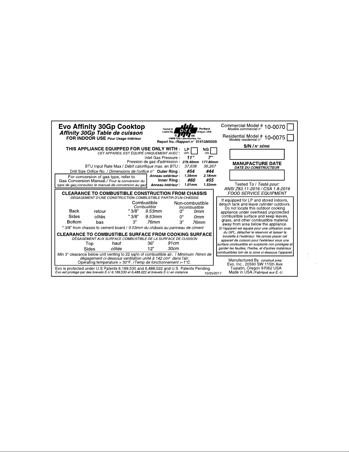
SAFETY LABEL

INSTALLATION INSTRUCTIONS
A f f i n i t y 3 0 G p
Evo, Inc., 20560 SW 115th Ave., Tualatin, OR 97062 USA
Phone 503.626.1802 | Fax 503.213.5869 | www.evoamerica.com | [email protected]
5
Evo, Incorporated warrants to the original residential consumer-purchaser that the Evo grill shall be free from rust-through on all
metal surfaces and shall be free from defects in materials and workmanship under normal and reasonable use from the original
date of purchase. Evo promises to replace, at its determination, any product or component that is defective and covered under this
warranty for as long as you, the registered original consumer-purchaser, owns the grill. This is your sole and exclusive remedy. This
warranty is for the benefi t of the original consumer-purchaser and is non-transferable. This warranty is subject to the limitations,
exclusions and other provisions listed below.
Limitations Involving Materials and Components:
Warranty does not apply to normal wear and tear, which are expected over the course of ownership. The materials and
components listed below are covered according to the following schedule from the original date of purchase:
• One Year – electrical and electronic components [including, but not limited to, electronic displays, overlay and membrane
switches, temperature sensors (RTD and K-Value Thermal Couple), hot surface igniters, computers, transformers,
heater elements, relays, igniters, ignition controllers, wiring, switches, encoders, outlets and plugs]
• One Year – gas components [including, but not limited to, gas regulator, gas hoses, manifold assemblies]
• One Year – accessories and repair parts
The Warranty Registration Card (or online warranty registration form available at www.evoamerica.com) must be
completed and returned/submitted to Evo, Incorporated within 30 days from the date of purchase. The original purchase
invoice or payment record must be retained and produced upon request if claims are made under this warranty. To
receive a replacement Warranty Registration Card, write or call the address listed at the bottom of this page. Warranties
are void if the original serial numbers have been removed, altered, or cannot be readily determined.
THIS WARRANTY APPLIES ONLY TO PRODUCTS PURCHASED AND LOCATED WITHIN THE UNITED STATES
OR CANADA.
WHAT IS NOT COVERED BY THIS WARRANTY
1. Conditions and damages resulting from any of the following:
a. Improper or inadequate installation, delivery, use, storage or maintenance
b. Any repair not authorized in writing by Evo, Inc., any modifi cations, misapplications, or unreasonable use
c. Improper setting of any control
d. Harsh environmental conditions, including, but not limited to, continual seawater spray, high pressure water, and direct contact
with corrosive chemicals and materials
e. Excessive or inadequate electrical, or gas supply
f. Accidents, natural disasters, acts of God
g. Conditions covered by the purchaser’s insurance
h. Cleaning supplies and fi lters
2. Products purchased or utilized for commercial use without the express authorization of Evo, Incorporated for such use
3. Labor not pre-authorized by Evo, Incorporated, and labor not performed by an authorized Evo service agency or representative
4. Pre-authorized warranty labor performed outside of normal business hours, and at overtime and premium rates
5. The cost of service or a service call to:
a. Identify or correct installation errors
b. Transport the product or component for service to/from the manufacturer or service center
c. Instruct the user of the proper use of the product
6. The cost for any inconvenience, personal injury or property damage due to failure of the product, and cost of damage arising out
of the transportation of the product which is covered under diff erent terms with the carrier
7. Natural variations in color and fi nishes that are inherent to the material and unavoidable (and therefore not defects)
ALL IMPLIED WARRANTIES, INCLUDING THE IMPLIED WARRANTIES OF MERCHANTABILITY, SUITABILITY,
QUALITY AND/OR FITNESS FOR A PARTICULAR PURPOSE, ARE LIMITED IN DURATION TO THE EXPRESS
WARRANTY PERIODS SPECIFIED ABOVE FOR THE PARTS DESCRIBED THEREIN. EVO, INCORPORATED
MAKES NO OTHER WARRANTY AND WILL NOT BE LIABLE FOR ANY DIRECT OR INDIRECT, CONSEQUENTIAL
OR INCIDENTAL DAMAGES. Some states do not allow limitations on how long an implied warranty lasts, so the above
limitation may not apply to you. Neither Evo manufacturer representatives and dealers, nor the retail establishment selling this
product has any authority to make any warranties or to promise remedies in addition to or inconsistent with those stated above.
The maximum liability to Evo, Incorporated in any event, shall not exceed the purchase price of the product paid by the original
consumer-purchaser. Some states do not allow the exclusion or limitation of incidental or consequential damages, so the above
limitations or exclusions may not apply to you. This warranty gives you specifi c legal rights, and you may also have other rights
which vary from state to state.
EVO RESIDENTIAL LIMITED WARRANTY TERMS

INSTALLATION INSTRUCTIONS
A f f i n i t y 3 0 G p
Evo, Inc., 20560 SW 115th Ave., Tualatin, OR 97062 USA
Phone 503.626.1802 | Fax 503.213.5869 | www.evoamerica.com | [email protected]
6
INSTALLATION CHECKLIST
UNPACK COOKTOP COMPONENTS 7
CLEARANCE DIMENSIONS 8
COUNTER TOP INSTALLATION 9 - 12
INSERT CHASSIS IN COUNTER TOP 13
INSTALL DRIP PAN AND DRIP PAN GASKET 14 - 15
ASSEMBLING COOK SURFACE RETAINING FASTENERS 16
CONNECTING AND INSTALLING COOKING SURFACE 17 - 18
INSTALLING COOKING SURFACE 19
RETENTION FASTENERS
CONNECTING INLET GAS LINE 20
SAFETY GAS PILOT LIGHT FUNCTIONALITY 21
BLEEDING AIR FROM THE GAS LINE 22
LIGHTING STANDING PILOT BURNERS 23
TEMPERATURE CONTROL 24
REMOVABLE SPILLOVER TRAYS 25
RECOGNIZING ABNORMAL GAS OPERATION 26
AFFINITY 30Gp DIMENSIONS 27
COOKING SURFACE MAINTENANCE 28
PAGE #
INSTALLATION INSTRUCTIONS
A f f i n i t y 3 0 G p
Evo, Inc., 20560 SW 115th Ave., Tualatin, OR 97062 USA
Phone 503.626.1802 | Fax 503.213.5869 | www.evoamerica.com | [email protected]
7
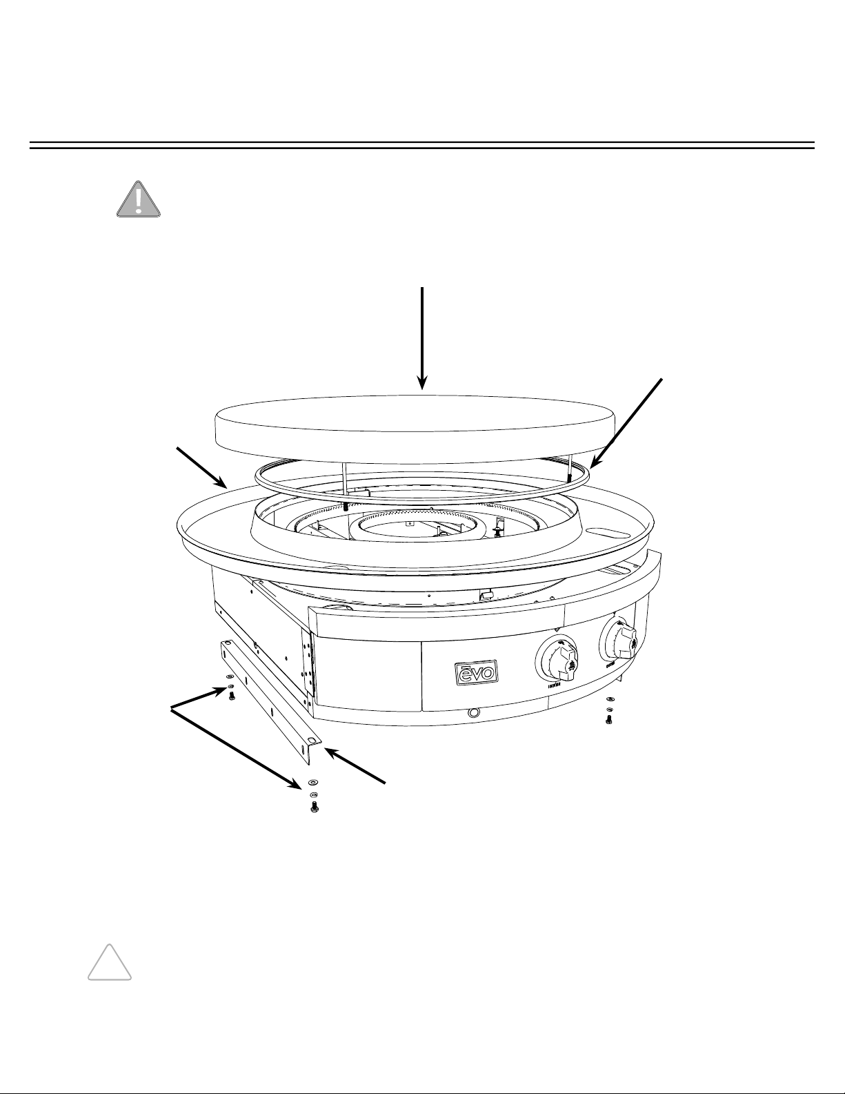
UNPACKING COOKTOP COMPONENTS
COOK SURFACE: LIFT AND SEPARATE COOK SURFACE FROM UNIT AND PLACE
NEXT TO INSTALLATION AREA.
DRIP PAN GASKET:
GASKET
INSTALLED TO
TOP OF DRIP TRAY.
REMOVE GASKET
FROM DRIP TRAY
AND SET ASIDE
FOR FINAL
INSTALLATION.
DRIP PAN:
UNLATCH PAN
FROM CIRCULAR
SKIRT, THEN
CAREFULLY LIFT
AND SEPARATE
DRIP PAN FROM
UNIT AND
PLACE NEXT TO
INSTALLATION
AREA. TAKE
CARE NOT TO
SCRATCH DRIP
PAN DURING
INSTALLATION.
CHASSIS:
LIFT CHASSIS
FROM CRATING
BOX AND PLACE
ON ITS SIDE NEXT
TO INSTALLATION
AREA.
METAL RIGHT ANGLE BRACKETS:
UNSCREW FROM UNIT AND KEEP
SCREWS AND BRACKETS HANDY
FOR FIRST INSTALLATION STEP.
As you are unpacking the crate, make sure you locate all components before installation.
Pilot light and ignition parts are exposed during uncrating and installation.
Use caution and do not alter factory set positions.
THE COOK SURFACE IS HEAVY. USE CAUTION WHEN LIFTING.
REMOVE TIE
DOWN BOLTS
AND TABS
HOLDING
CHASSIS TO
PACKING
CRATE BASE
USING 7/16”
WRENCH.
INSTALLATION INSTRUCTIONS
A f f i n i t y 3 0 G p
Evo, Inc., 20560 SW 115th Ave., Tualatin, OR 97062 USA
Phone 503.626.1802 | Fax 503.213.5869 | www.evoamerica.com | [email protected]
8
CLEARANCE DIMENSIONS
Read the instructions carefully in this booklet to install the
Evo Affi nity 30Gp Cooktop to a metal, stone or wood counter top surface.
Cabinet layout and construction may vary.
CLEARANCE TO COMBUSTIBLE CONSTRUCTION FROM CHASSIS
Combustibles Non-combustibles
Back * 3/8” 0”
Sides * 3/8” 0”
Bottom 3” 3”
CLEARANCE TO COMBUSTIBLE CONSTRUCTION FROM COOKING SURFACE
Top 36”
Sides 12”
Back 12”
36” CLEARANCE FROM COOKING
SURFACE TO COMBUSTIBLE
CEILING MATERIALS.
12” CLEARANCE
FROM COOKING
SURFACE TO
COMBUSTIBLE
SIDEWALL
MATERIALS.
12” CLEARANCE
FROM COOKING
SURFACE TO
COMBUSTIBLE
BACK WALL
MATERIALS.
The minimum environmental temperature for safe use of the Evo Affi nity 30Gp
should not be below 32°F ( 0° C).
IF INSTALLING
ALONGSIDE
ANOTHER 30Gp
UNIT, PROVIDE
2” MINIMUM
CLEARANCE
FROM EDGE
OF DRIP PANS.
Minimum 3” clearance required under unit venting to 22 sq../in of combustible air.
* 3/8” of cement board lined enclosure to chassis.
INSTALLATION INSTRUCTIONS
A f f i n i t y 3 0 G p
Evo, Inc., 20560 SW 115th Ave., Tualatin, OR 97062 USA
Phone 503.626.1802 | Fax 503.213.5869 | www.evoamerica.com | [email protected]
9
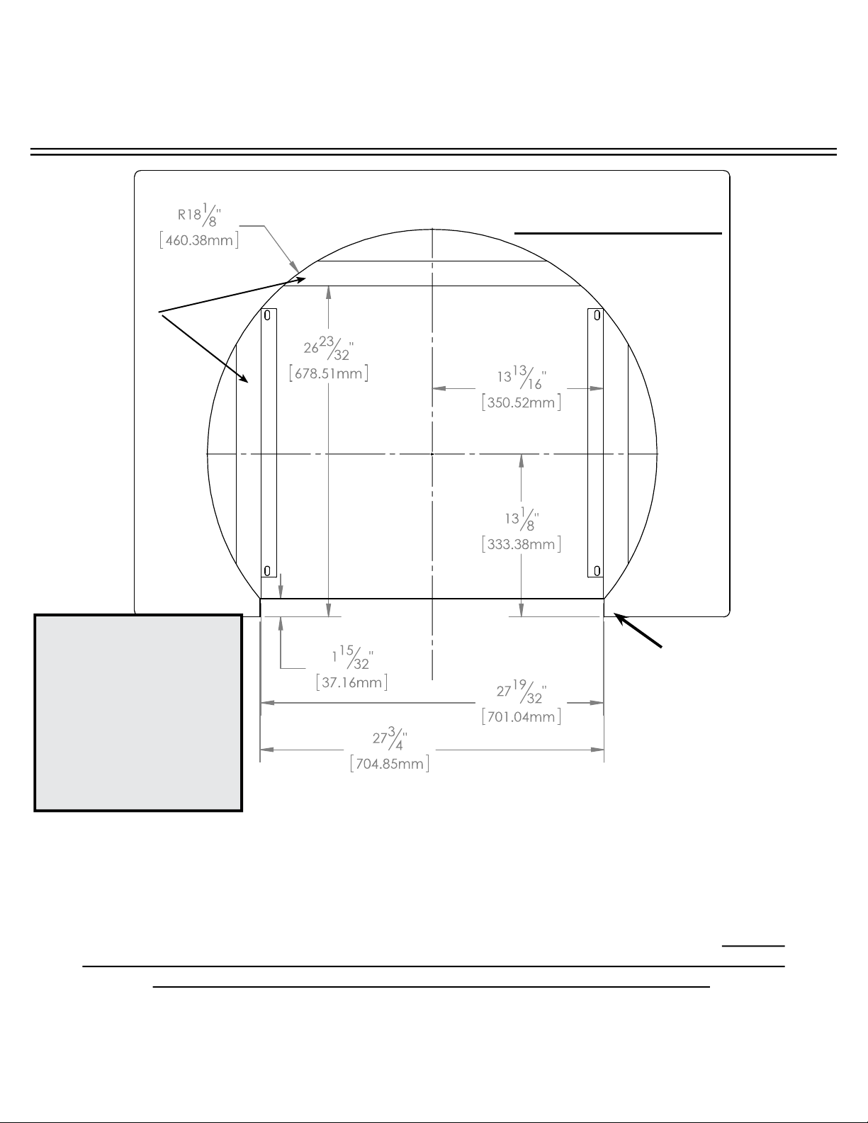
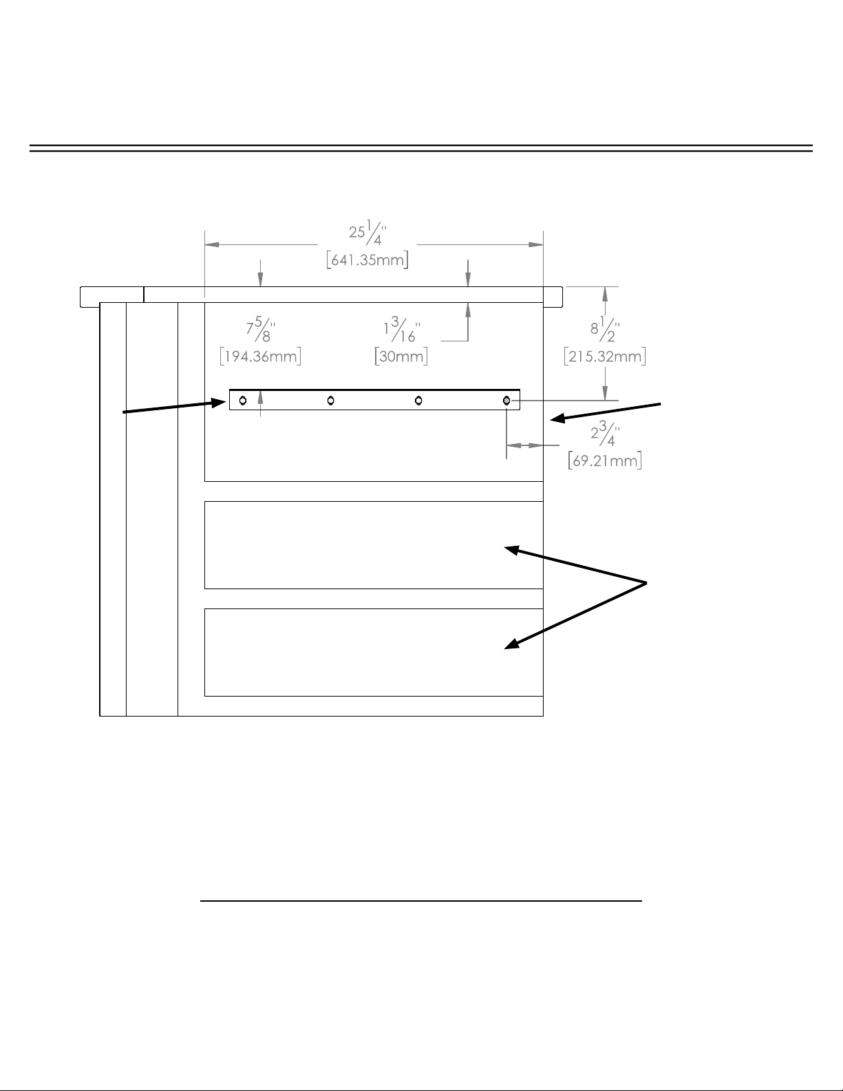
Mark the fi nished position of the Evo Affi nity 30Gp drip pan on the counter top using the
dimensions shown. The circular dimension of 36.25” is the diameter of the drip pan to the
outside fl ange material thickness (located to the inside of the half-rolled bead edge). The drip
pan cutout must be made precisely to these dimensions (or at a maximum +1/16”) so the half-
rolled bead on the drip pan edge overhangs the cutout dimension by 0.25”.
(See following page for more detail)
COUNTER TOP WITH
SUBSTRATE UNDERLAYMENT
OPENING IN COUNTER TOP
FRONT
COUNTER TOP
OVERHANG TO
CABINET FRONT
CABINETRY BOX:
MINIMUM 1-3/16”
(3CM) BELOW
COUNTER TOP
SURFACE.
TOP VIEW
COUNTER TOP INSTALLATION (1 of 4)
NOTE:
If the dimensions for the
counter top overhang
and counter top depth
cutout are not followed,
there will be a confl ict
with the door swing
which allows access to
the waste containers.
INSTALLATION INSTRUCTIONS
A f f i n i t y 3 0 G p
Evo, Inc., 20560 SW 115th Ave., Tualatin, OR 97062 USA
Phone 503.626.1802 | Fax 503.213.5869 | www.evoamerica.com | [email protected]
10
SHELVING OR
DRAWERS
CAN BE
INSTALLED
UNDER
THE UNIT IF
DESIRED.
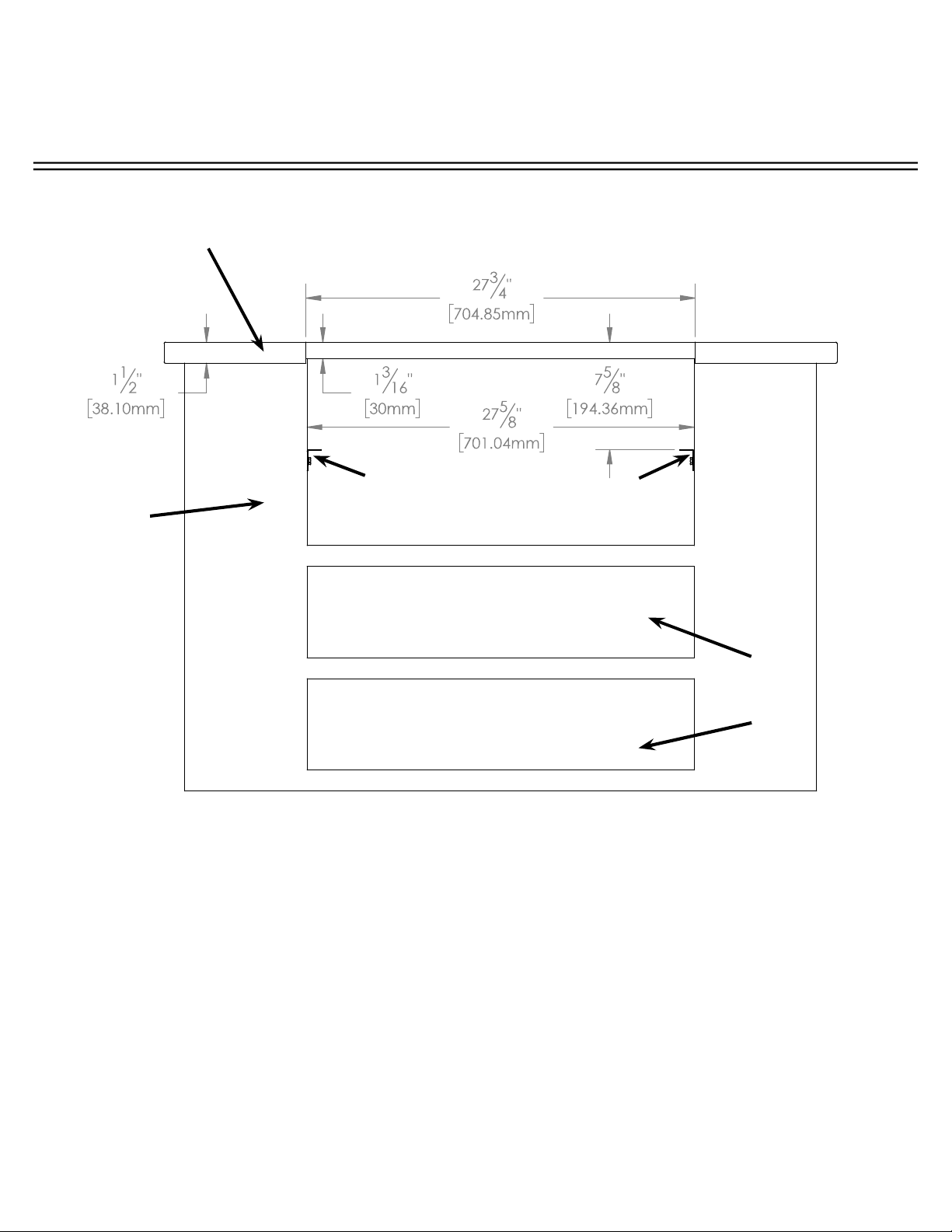
FRONT VIEW
Construct a bay for the Evo unit with your chosen cabinet system. Position and fasten the
supplied mounting brackets 7-21/32” below the fi nished counter top surface.
Metal right angle mounting brackets supplied with unit are
1/16” thick. Mount angle brackets as shown. Unit slides into
framework and rests on top of brackets.
Brackets are slotted for fasteners at each four corners.
CABINET
FRAMEWORK
EXAMPLE: TILED COUNTER TOP WITH
SUBSTRATE. FINISHED COUNTER TOP
THICKNESS SHOULD BE 1-3/16” (3CM).
COUNTER TOP INSTALLATION (2 of 4)
INSTALLATION INSTRUCTIONS
A f f i n i t y 3 0 G p
Evo, Inc., 20560 SW 115th Ave., Tualatin, OR 97062 USA
Phone 503.626.1802 | Fax 503.213.5869 | www.evoamerica.com | [email protected]
11
SIDE VIEW
Example of 3/8” tile with substrate for a minimum 1-3/16” (3cm) overall.
Make sure you allow for the counter top overhang as shown.
METAL
RIGHT
ANGLE
MOUNTING
BRACKETS
(SUPPLIED)
IF DESIRED,
SHELVING OR
DRAWERS CAN
BE INSTALLED
UNDER THE UNIT
IF DESIRED.
FINISHED CABINET
FACE SET BACK
FROM FINISHED
COUNTER TOP
FRONT EDGE
COUNTER TOP INSTALLATION (3 of 4)
INSTALLATION INSTRUCTIONS
A f f i n i t y 3 0 G p
Evo, Inc., 20560 SW 115th Ave., Tualatin, OR 97062 USA
Phone 503.626.1802 | Fax 503.213.5869 | www.evoamerica.com | [email protected]
12
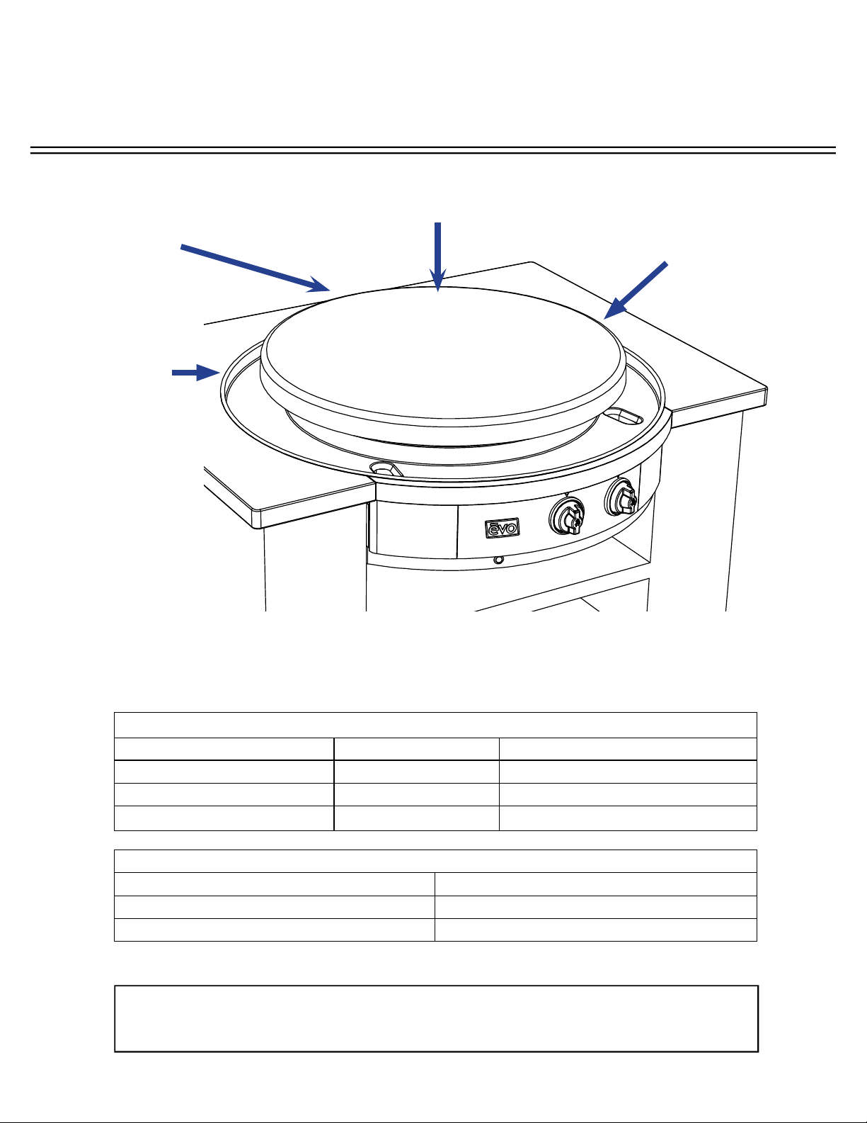
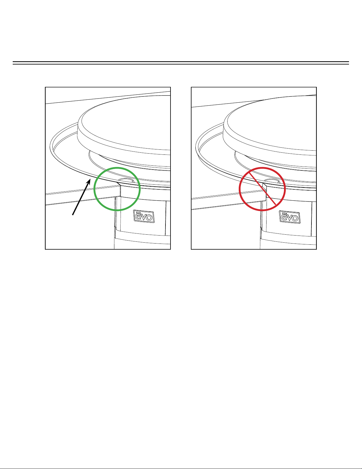
COUNTER TOP INSTALLATION (4 of 4)
CORRECT ALIGNMENT OF DRIP PAN
AND CHASSIS TO COUNTER TOP
INCORRECT ALIGNMENT OF DRIP PAN
AND CHASSIS TO COUNTER TOP
BLACK O-RING
UNDER DRIP
PAN BEAD
Make sure cabinetry box is 1-1/2” below counter top surface and mounting brackets are
positioned correctly so drip pan and chassis are aligned to counter top. (see diagrams above).
A black o-ring is recessed in the top bead and designed to create a seal against the counter
top.
POSSIBLE REASONS FOR INCORRECT ALIGNMENT:
1. TOP OF CABINETRY BOX IS LESS THAN 1-3/16” (3CM) FROM COUNTER TOP.
2. CHASSIS MOUNTING BRACKETS ARE TOO HIGH.
INSTALLATION INSTRUCTIONS
A f f i n i t y 3 0 G p
Evo, Inc., 20560 SW 115th Ave., Tualatin, OR 97062 USA
Phone 503.626.1802 | Fax 503.213.5869 | www.evoamerica.com | [email protected]
13
INSERT CHASSIS IN COUNTER TOP
Gas Installation must be done by a licensed plumber in accordance with
local guidelines once unit has been completely installed. Refer to pages 17-
18 and 21 for further instructions.
Slide the Affi nity 30Gp chassis into the counter top mounting enclosure so it rests on top of
the installed brackets. Bolt unit to angle brackets using supplied 1/4” x 20 fasteners.
USE SUPPLIED 1/4” FASTENERS
TO BOLT CHASSIS TO ANGLE
BRACKETS.
INSTALLATION INSTRUCTIONS
A f f i n i t y 3 0 G p
Evo, Inc., 20560 SW 115th Ave., Tualatin, OR 97062 USA
Phone 503.626.1802 | Fax 503.213.5869 | www.evoamerica.com | [email protected]
14
Slide drip tray over chassis circular skirt positioning spillover slots to the corresponding
slots of the top chassis deck. Notice the drip pan catches showing through the inside cutout
locations of the circular chassis skirt. From the inside of the skirt, use each of the three
latches to pull the drip pan down into the counter.
DRIP
TRAY
CATCH
POSITIONING DRIP PAN
INSTALLATION INSTRUCTIONS
A f f i n i t y 3 0 G p
Evo, Inc., 20560 SW 115th Ave., Tualatin, OR 97062 USA
Phone 503.626.1802 | Fax 503.213.5869 | www.evoamerica.com | [email protected]
15
SECURING DRIP PAN AND GASKET
Secure drip pan to chassis using access slot (A). Rewrap drip pan gasket around top of drip
tray and secure (B). Ensure seal under drip pan edge is touching counter top(C).
DRIP PAN
GASKET SEAM
AT REAR
CROSS SECTION OF
CHASSIS ACCESS SLOT
Hook drip pan latch under
chassis catch and tighten
screw at chassis access slot.
A
Slip gasket ring onto top of
drip pan so it creates a seal to
the chassis skirt.
CROSS SECTION OF
DRIP PAN TOP
CROSS SECTION OF
DRIP PAN EDGE
Ensure the black seal under
the drip pan bead edge is
touching the counter top.
B C
Drip
Pan
Counter
Top
Drip Pan
Chassis
Skirt
USE NO. 3 PHILLIPS
SCREWDRIVER TO SECURE
DRIP PAN AT THE ACCESS
POINTS.
INSTALLATION INSTRUCTIONS
A f f i n i t y 3 0 G p
Evo, Inc., 20560 SW 115th Ave., Tualatin, OR 97062 USA
Phone 503.626.1802 | Fax 503.213.5869 | www.evoamerica.com | [email protected]
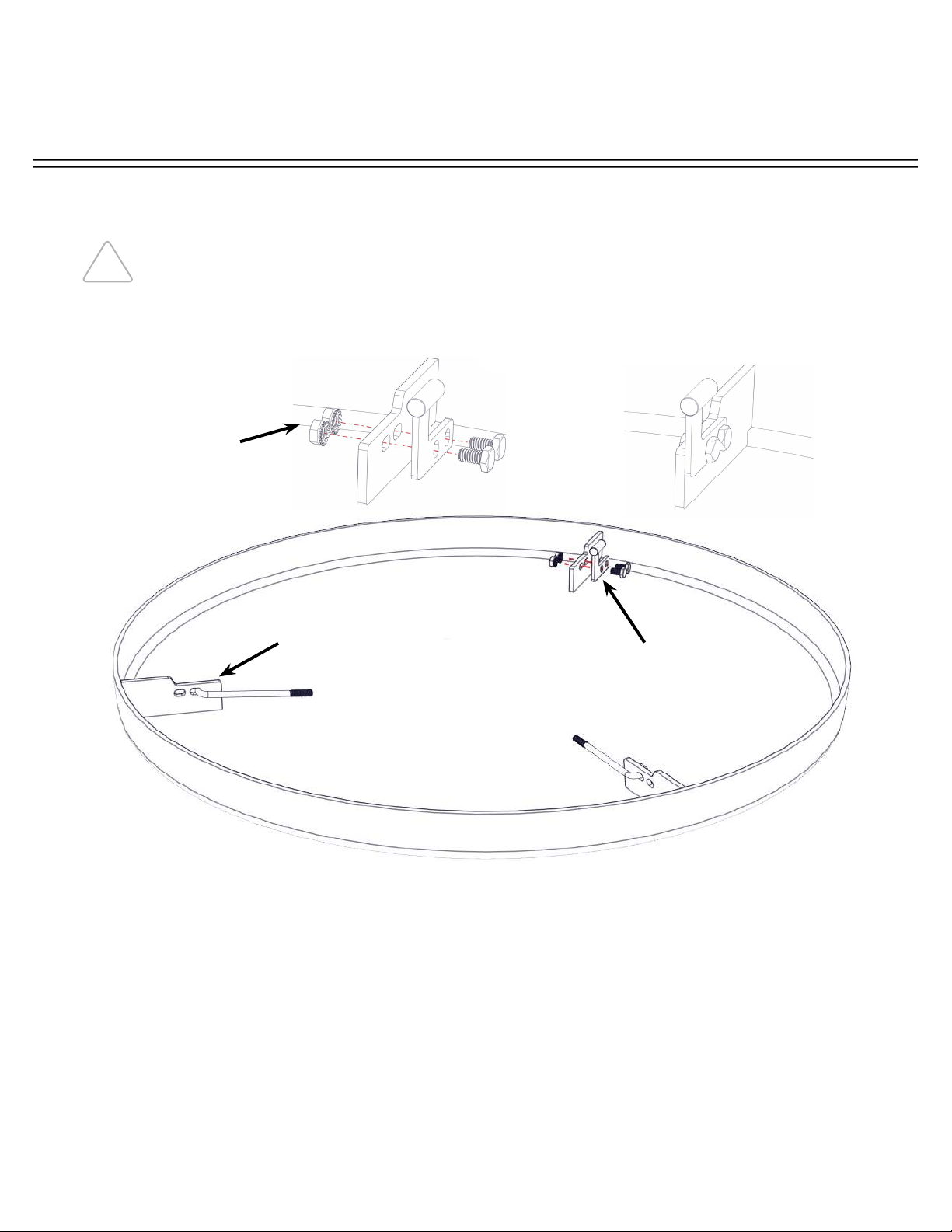
16
Locate Parts Box shipped your Affi nity 30Gp and the parts bag containing the Rear Retaining
Bullet Fastener, two each 1/4” x 20 hex bolt and locking nut, and two each J-Hook. Follow
the illustration show on this page. Using a 7/16” wrench tighten the Rear Retaining Bullet to a
cook surface tab as shown (Ensure the Rear Retaining Bullet is placed on the right hand side
of the tab). Next, loop the J-Hook through the inside slot of each remaining tab.
ASSEMBLING COOK SURFACE RETAINING FASTENERS
IT IS RECOMMENDED THE COOKING SURFACE BE PLACED ON A PROTECTED
WORK SURFACE WITH THE FLANGE FACING UPWARD.
PLACE REAR
RETAINING BULLET
FASTENER ON RIGHT
HAND SIDE OF TAB.
USING A 7/16”
WRENCH, TIGHTEN
THE REAR RETAINING
BULLET TO THE
COOKING SURFACE
TAB WITH TWO EACH
1/4” X 20 HEX BOLT
AND LOCKING NUT.
ENSURE THE BOLTS
ARE TIGHTENED
SECURELY.
LOOP THE J-HOOK
THROUGH THE
INSIDE SLOT OF
TWO TABS AS
SHOWN.
INSTALLATION INSTRUCTIONS
A f f i n i t y 3 0 G p
Evo, Inc., 20560 SW 115th Ave., Tualatin, OR 97062 USA
Phone 503.626.1802 | Fax 503.213.5869 | www.evoamerica.com | [email protected]
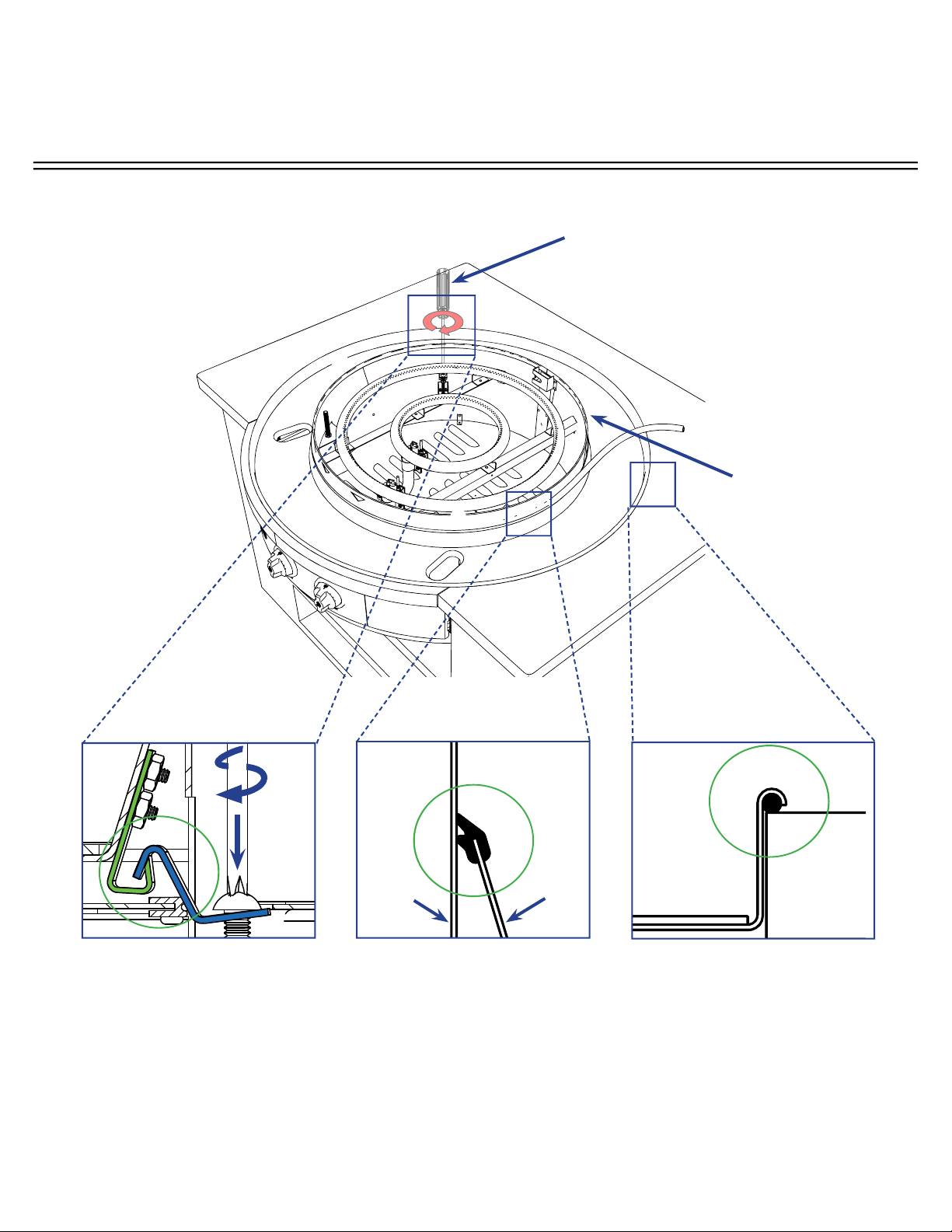
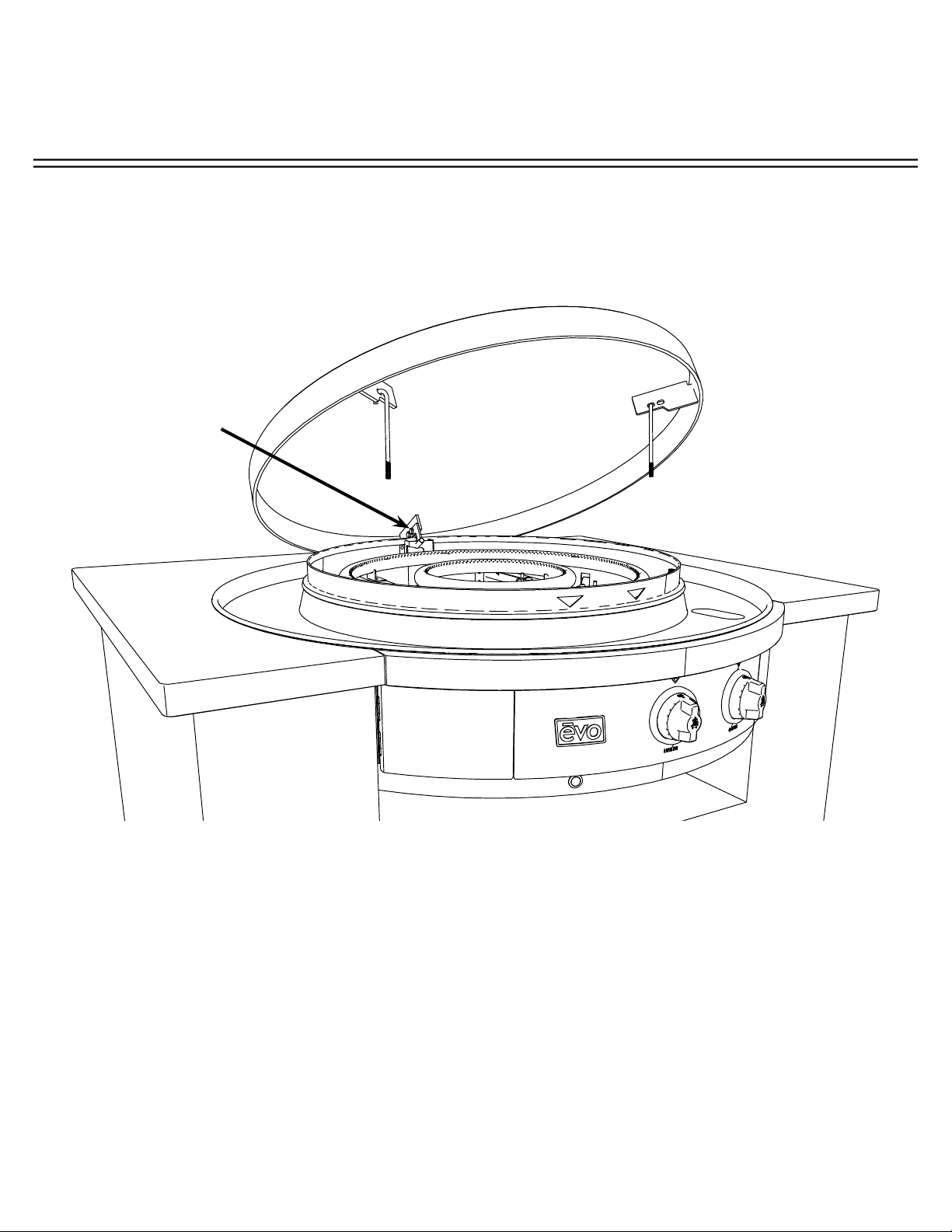
17
Place cook surface on an angle with Bullet Fastener facing down and rearward. Engage bullet fastener
to keyway slot on chassis back wall and lower J-Hooks into front threaded tubes.
PLACE COOK SURFACE
ON AN ANGLE WITH
BULLET FASTENER
FACING DOWN AND
REARWARD, ENGAGE
BULLET FASTENER
TO KEYWAY SLOT
ON CHASSIS BACK
WALL AND LOWER
J-HOOKS INTO FRONT
THREADED TUBES.
CONNECTING COOK SURFACE
INSTALLATION INSTRUCTIONS
A f f i n i t y 3 0 G p
Evo, Inc., 20560 SW 115th Ave., Tualatin, OR 97062 USA
Phone 503.626.1802 | Fax 503.213.5869 | www.evoamerica.com | [email protected]
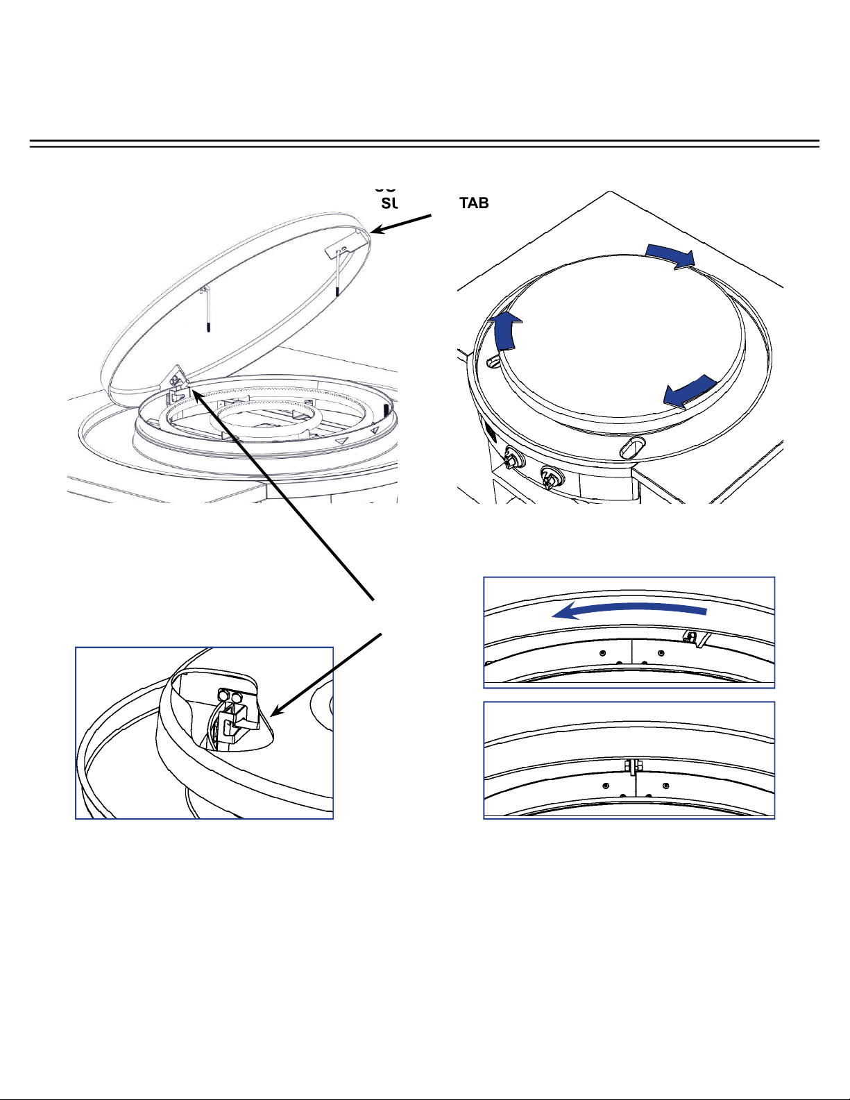
18
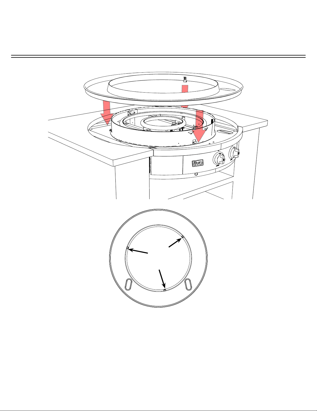
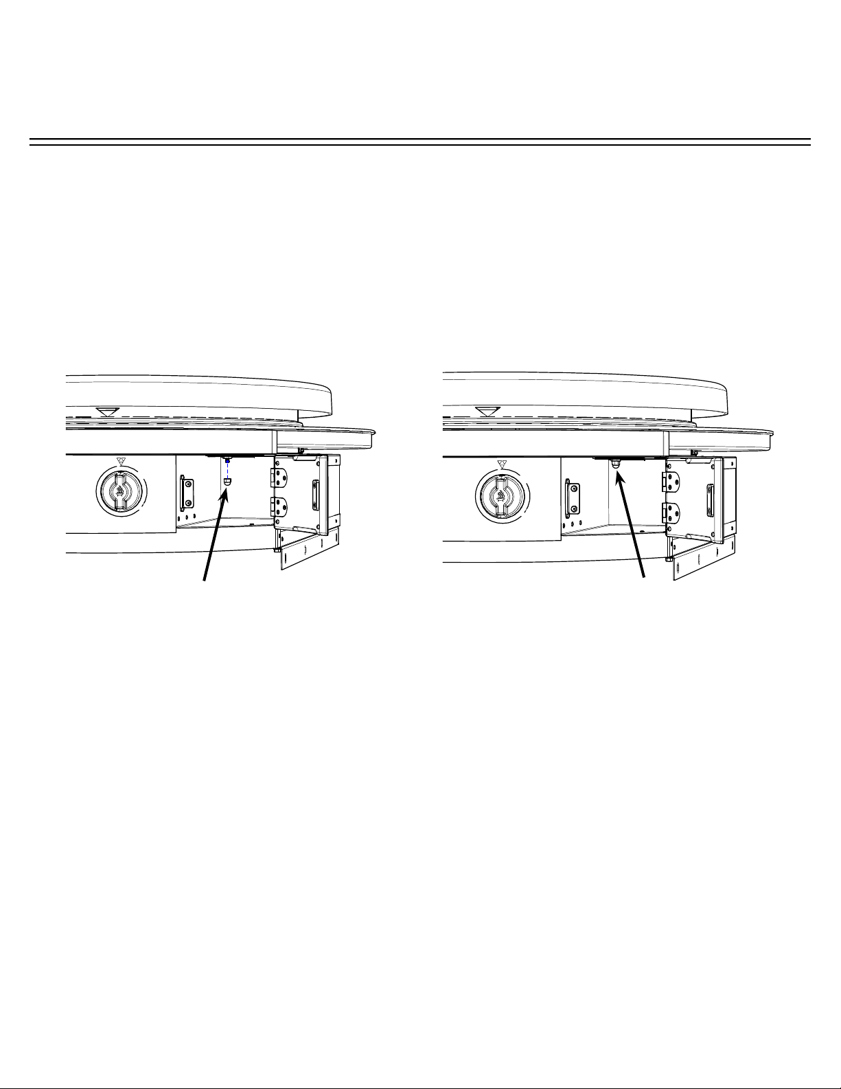
Place cook surface over circular skirt with the three support tabs (located under cook surface)
resting on top the chassis skirt. Position the rear support tab of the cook surface to the right
of the rear seam of the chassis skirt (A). Next rotate the cook surface clockwise until the
support tab is in line with the seam (B) and the rear bullet is secure in the chassis slot (C).
COOK SURFACE
SUPPORT TAB
INSTALLING COOK SURFACE
BOTTOM-UP VIEW OF
REAR COOK SURFACE
CUT AWAY VIEW OF REAR COOK
SURFACE SHOWING BULLET
ENGAGED IN CHASSIS SLOT
A
B
C
REAR BULLET
INSTALLATION INSTRUCTIONS
A f f i n i t y 3 0 G p
Evo, Inc., 20560 SW 115th Ave., Tualatin, OR 97062 USA
Phone 503.626.1802 | Fax 503.213.5869 | www.evoamerica.com | [email protected]
19
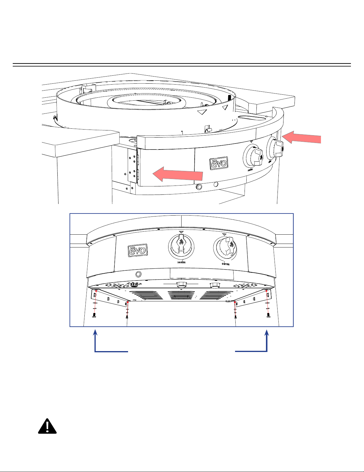
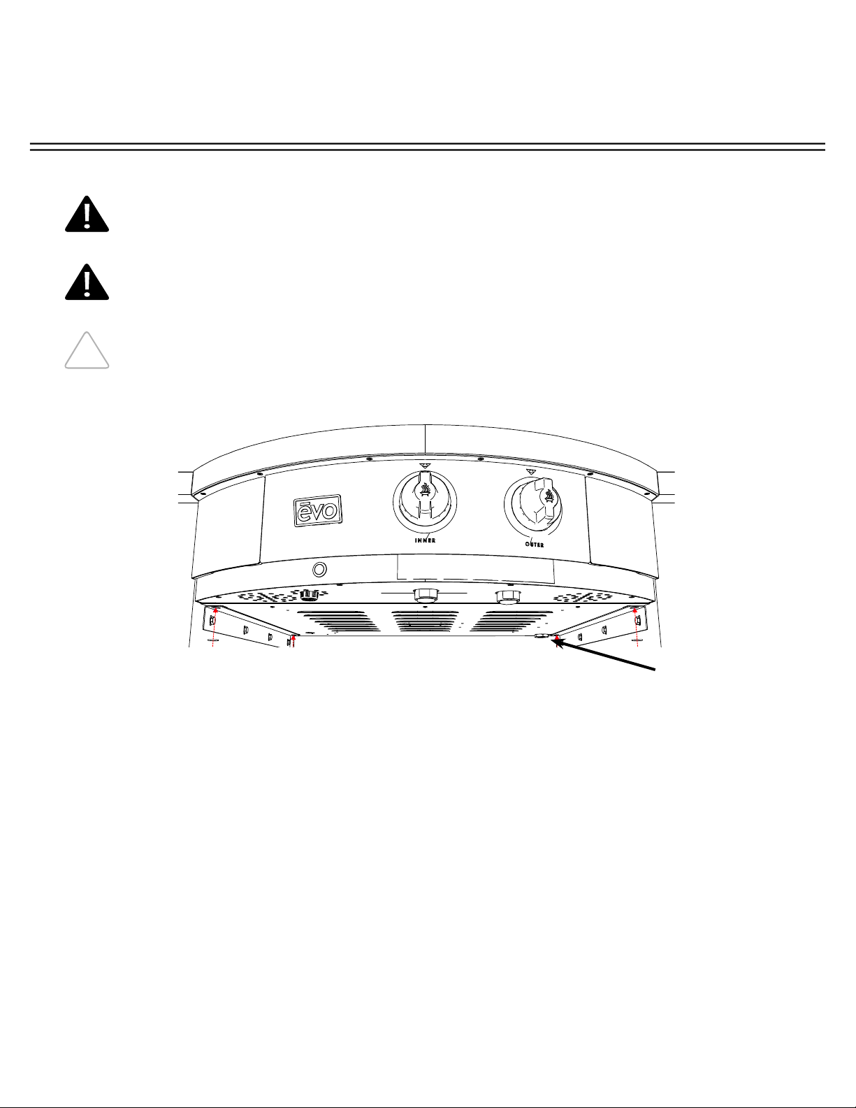
INSTALLING COOKING SURFACE RETAINING FASTENERS
Open both waste doors and at the rear inside corner of the enclosure, tighten 1/4” X 20 nut
on end of J-Hook to retain cooking surface for burner chassis.
OPEN WASTE
DOORS TO LOCATE
END OF J-HOOK.
TIGHTEN 1/4” X 20
NUT AT END OF
EACH J-HOOK.
INSTALLATION INSTRUCTIONS
A f f i n i t y 3 0 G p
Evo, Inc., 20560 SW 115th Ave., Tualatin, OR 97062 USA
Phone 503.626.1802 | Fax 503.213.5869 | www.evoamerica.com | [email protected]
20
NATURAL GAS CONNECTION:
Connect gas using 7” W.C (max) gas service.
LP PROPANE GAS CONNECTION:
Connect gas using 11” Water Column (Fixed) gas service.
SHUT OFF VALVE FOR GAS CONNECTION:
It is recommended to have an easily accessible gas shut off valve mounted under the unit
nearest the Inlet Gas Supply to shut off the pilot burners nightly and for easy access during
repairs.
CONNECTING INLET GAS LINE
FOR YOUR PROTECTION, A QUALIFIED PLUMBER MUST INSTALL THIS
COOKTOP. THIS PERSON MUST BE FAMILIAR WITH GAS INSTALLATIONS AND
ALL LOCAL CODES. PROPER CONNECTIONS ARE ESSENTIAL FOR SAFE AND
EFFICIENT OPERATION.
GAS PRESSURES MUST BE CONFIGURED FOR THE TYPE OF GAS USED
EITHER NATURAL GAS OF LP PROPANE GAS.
GAS SUPPLY
1) Natural Gas 7” W.C. Maximum Inlet Gas Pressure.
2) LP Propane Gas 11” W.C. Maximum Inlet Gas Pressure.
ONCE THE CHASSIS IS INSTALLED AND BEFORE CONNECTING TO AN INLET
GAS SUPPLY, IT’S RECOMMENDED TO BLEED THE INPUT GAS LINE OF AIR TO
REDUCE THE TIME TO ENGAGE THE GAS PILOT LIGHT BURNERS.
Inlet Gas Supply
Bulkhead Fitting
INSTALLATION INSTRUCTIONS
A f f i n i t y 3 0 G p
Evo, Inc., 20560 SW 115th Ave., Tualatin, OR 97062 USA
Phone 503.626.1802 | Fax 503.213.5869 | www.evoamerica.com | [email protected]
21
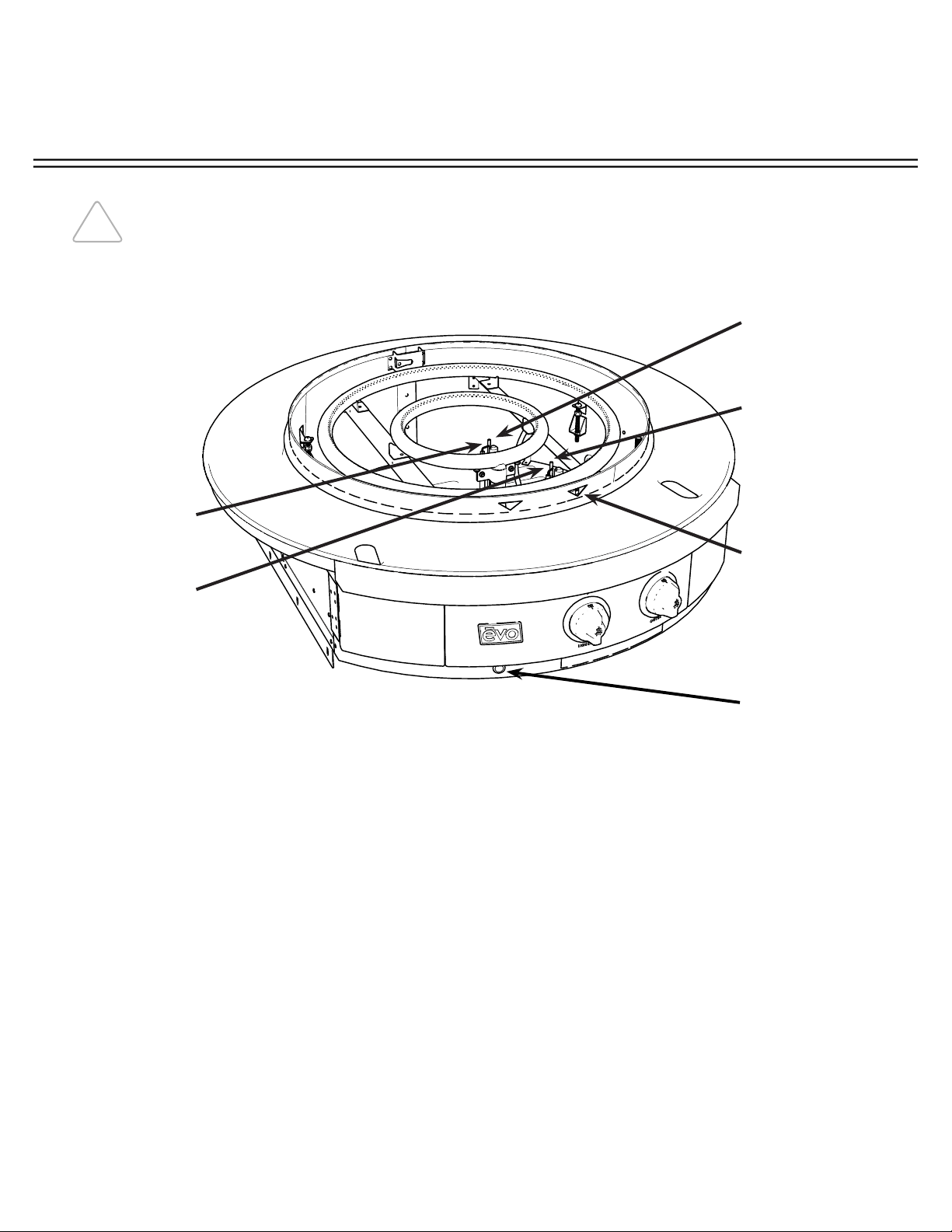
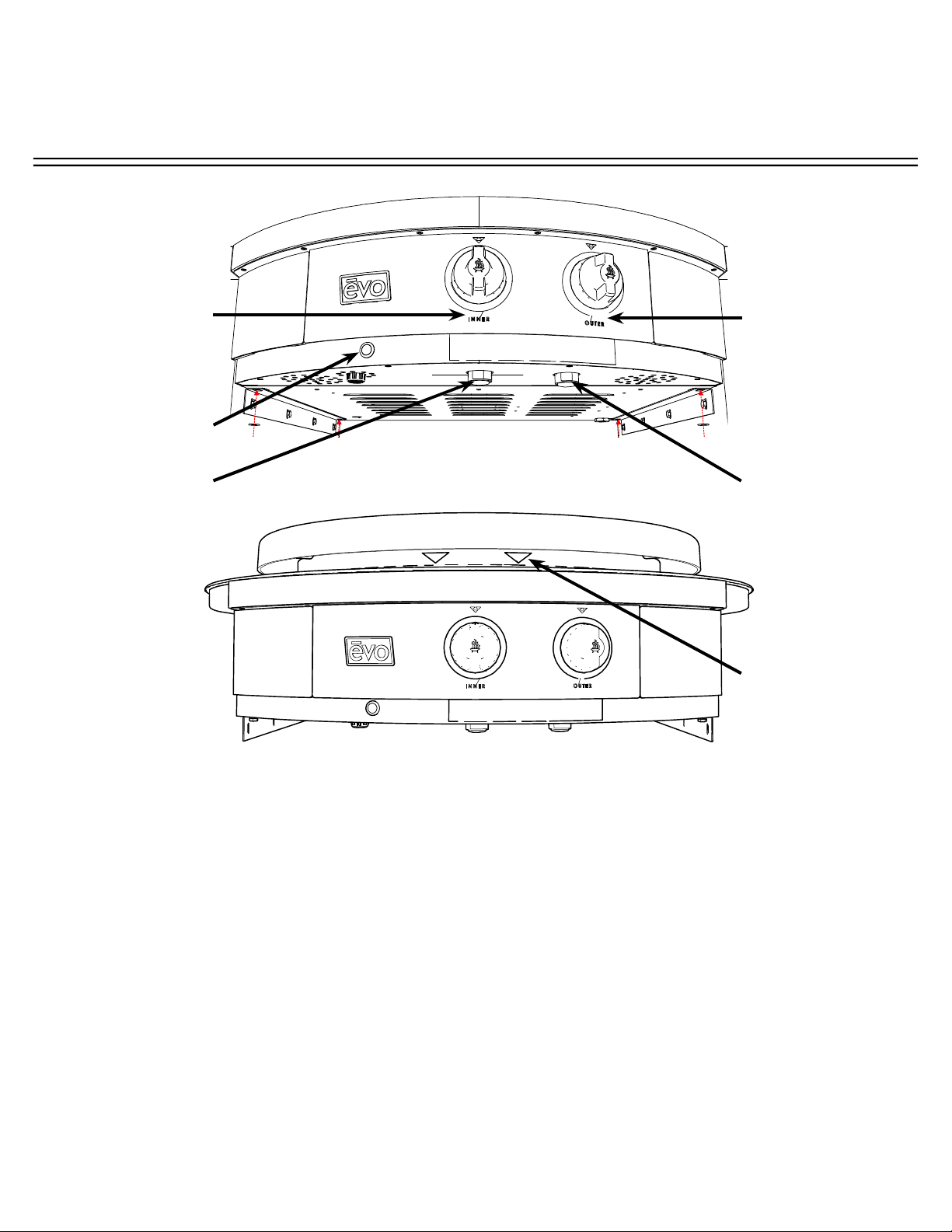
SAFETY GAS PILOT LIGHT FUNCTION:
The Affi nity 30Gp is equipped with two independently controlled circular gas burners, two Safety
Gas Pilot Light valves, and a dual piezo spark ignition system. The gas pilots for both the inner
and outer burners consist of a pre-confi gured pilot burner orifi ce/jet specifi cally for either Natural
Gas or LP Propane Gas operation.
The purpose of the Safety Pilot Valve is to ensure no gas fl ows to the main burner manifold
unless the gas pilot’s are burning. When a pilot light is burning, it heats a Thermocouple probe
which opens the safety valve and allows gas to fl ow. This “safety” feature controls situations
where a gas knob is turned on and no fl ame is present, thereby eliminating unburned gas into an
occupied space.
It is recommended the gas pilot light burners be shut off each night to minimize gas usage.
SAFETY GAS PILOT LIGHT FUNCTIONALITY
ONCE THE CHASSIS IS INSTALLED AND BEFORE CONNECTING TO AN INLET
GAS SUPPLY, IT’S RECOMMENDED TO BLEED THE INPUT GAS LINE OF AIR TO
REDUCE THE TIME TO ENGAGE THE SAFETY GAS PILOT LIGHT BURNERS.
INNER GAS
PILOT BURNER
OUTER GAS
PILOT BURNER
FLAME VIEWING
PORTALS
OUTER
THERMOCOUPLE
AND IGNITION ROD
INNER
THERMOCOUPLE
AND IGNITION ROD
IGNITION
BUTTON
INSTALLATION INSTRUCTIONS
A f f i n i t y 3 0 G p
Evo, Inc., 20560 SW 115th Ave., Tualatin, OR 97062 USA
Phone 503.626.1802 | Fax 503.213.5869 | www.evoamerica.com | [email protected]
22
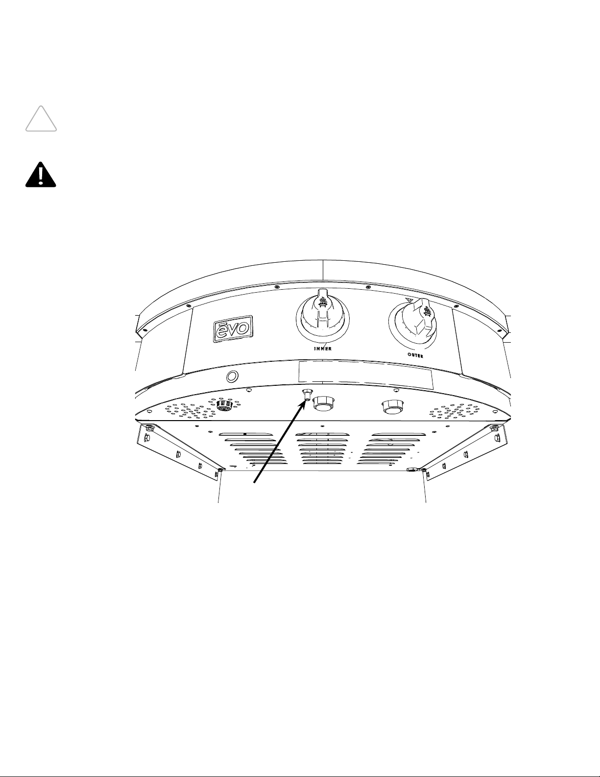
BLEEDING AIR FROM GAS LINE
IT IS IMPORTANT TO BLEED OUT THE GAS LINE, OR ‘PURGE’, TO ENSURE ALL
AIR POCKETS ARE REMOVED. IF YOU DO NOT BLEED YOUR GAS LINE AND
THERE ARE AIR POCKETS IN THE LINE YOUR APPLIANCE MAY NOT START
How To Bleed The Gas Line:
Step 1: Turn on gas at the gas inlet valve (external to the evo appliance and supplied by others).
Step 2: Locate the gas bleed port, and using a small fl at-blade screwdriver, open the gas bleed screw until all the air
is purged from the gas line and until there is a faint smell of gas and then immediately close the bleed screw.
Step 3: It is extremely important to ensure the gas bleed screw is completely closed to prevent gas from leaking from
the gas bleed port.
IT IS EXTREMELY IMPORTANT TO ENSURE THE GAS BLEED SCREW IS COMPLETELY
CLOSED TO PREVENT GAS FROM LEAKING FROM THE GAS BLEED PORT OR
POTENTIALLY HAZARDOUS SITUATION WHICH, IF NOT AVOIDED, COULD RESULT IN
DEATH OR SERIOUS INJURY
GAS BLEED PORT
INSTALLATION INSTRUCTIONS
A f f i n i t y 3 0 G p
Evo, Inc., 20560 SW 115th Ave., Tualatin, OR 97062 USA
Phone 503.626.1802 | Fax 503.213.5869 | www.evoamerica.com | [email protected]
23
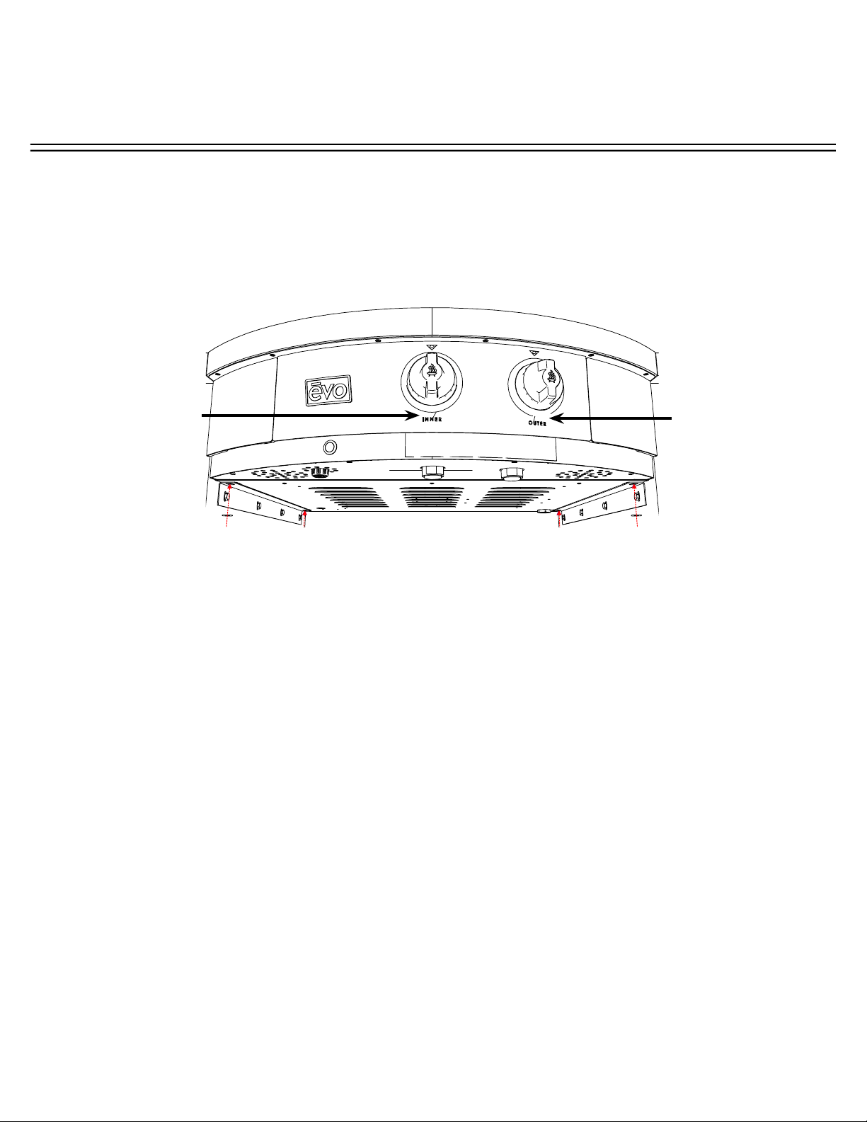
LIGHTING STANDING PILOT BURNERS
To Light The Inner and Outer Standing Pilot Burners:
STEP 1: The external gas shut-off valve must be in the ON position.
STEP 2: Press the Ignition Button and simultaneously press the Inner Burner Pilot Light Button. It may
be necessary to keep the pilot light button depressed for several minutes if air in the gas line was not
bled before installation. Check to see if the gas pilot light is burning by visually inspecting through the
Flame Viewing Portals for the presence of a fl ame. Once a fl ame is present, stop pressing the Ignition
Button and continue pressing the pilot light button for an additional 30 seconds to 1 minute to allow the
Thermocouple to become hot and the Pilot Safety Valve to open.
STEP 3: Once a steady fl ame is witnessed, release the Inner Burner Pilot Light Button and confi rm the
pilot light continues to burn. If the pilot light fails or extinguishes, then repeat Step 1. The most common
reason for the pilot light sequence to fail is the pilot light button is not held long enough to heat the
thermocouple, or there’s an excess amount of air in the inlet gas line created during installation. With
the pilot safety valve open, full functionality to the inner and outer burners is now available.
STEP 4: Repeat steps 1 and 2 for the Outer Burner Pilot Light. With both the inner and outer pilot light
burners lit and continuously burning, full functionality to the inner and outer main tube burners is now
available.
TRIANGULAR
FLAME VIEWING
PORTALS
INNER BURNER
CONTROL KNOB
OUTER BURNER
CONTROL KNOB
IGNITION
BUTTON
INNER
Pilot Light
Button
OUTER
Pilot Light
Button
OPERATOR INSTRUCTIONS
A f f i n i t y 3 0 G p
Evo, Inc., 20560 SW 115th Ave., Tualatin, OR 97062 USA
Phone 503.626.1802 | Fax 503.213.5869 | www.evoamerica.com | [email protected]
24
TEMPERATURE CONTROL
How To Adjust Inner and Outer Temperature Control Knobs:
With both the inner and outer pilot light burners lit and continuously burning, select the inner or outer or
both control knobs and choose a temperature setting between Hi, Med and Low.
To control temperature across the entire cooking surface, select an appropriate temperature based on the
food being prepared using both the inner and outer control knobs. If focused temperature is required at
the center of the cooking surface, choose a temperature setting using only the inner control knob, leaving
the outer control knob set to Low or Off . In a similar way, if focused temperature is required at the outer
diameter of the cooking surface, then choose a temperature using only the outer control knob, leaving the
inner knob set to Low or Off .
Representative Temperatures For Low, Med and Hi Control Knob Settings:
Temperature settings using both the inner and outer control knobs set to Low, Med and Hi are as follows:
Inner knob set to Lo = 237F (Outer Off ), Inner knob set to Med = 310F (Outer Off ), Inner knob set to Hi =
368F (Outer Off )
Outer knob set to Lo = 225F (Inner Off ), Inner knob set to Med = 304F (Inner Off ), Inner knob set to Hi =
405F (Inner Off )
Inner and Outer knob set to Lo = 358F, Inner and Outer knob set to Med = 450F, Inner and Outer knob
set to Hi = 522F.
Diff erences in altitude and inlet gas pressure less than recommended 7”W.C for NG and 11”W.C
for LP will cause a variation in set temperature.
INNER
MAIN BURNER
CONTROL KNOB
OUTER
MAIN BURNER
CONTROL KNOB
OPERATOR INSTRUCTIONS
A f f i n i t y 3 0 G p
Evo, Inc., 20560 SW 115th Ave., Tualatin, OR 97062 USA
Phone 503.626.1802 | Fax 503.213.5869 | www.evoamerica.com | [email protected]
25
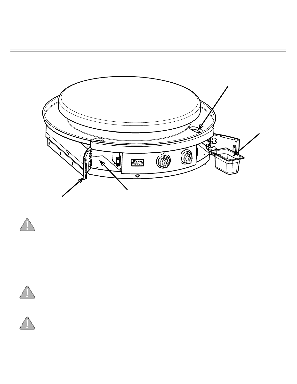
REMOVABLE SPILLOVER TRAYS
The Affi nity grill has removable waste pans concealed in doors on both the right and left side of the
front control panel. It is very important to monitor the level of spillover in the trays, and immediately
empty when they are near full or after each use.
Opening Spillover Tray Doors - To open a door, grasp the door at its bottom and pull forward.
Do not operate cook top or clean drip pan into spillover slots without waste pans
installed in spillover doors. Failure to install waste pan will result in cooking grease
contamination to the underside of door. This requires immediate cleaning.
Do not allow spillover liquids or debris down spillover slots when doors are open. Any
liquids or debris that may fall into this area when doors are open should be immediately
wiped with a dry cloth, and keep this area clean at all times.
Do not allow the spillover trays to overfl ow, and do not allow full trays to splash over
edge when cleaning. Spillover debris and liquids can be hot and cause burns, and/or
damage to the internal operation of the grill.
Removable
Waste Pan
Access
Door
Spillover Slot
Insert waste pan fully into the back of
the left and right compartments.
OPERATOR INSTRUCTIONS
A f f i n i t y 3 0 G p
Evo, Inc., 20560 SW 115th Ave., Tualatin, OR 97062 USA
Phone 503.626.1802 | Fax 503.213.5869 | www.evoamerica.com | [email protected]
26
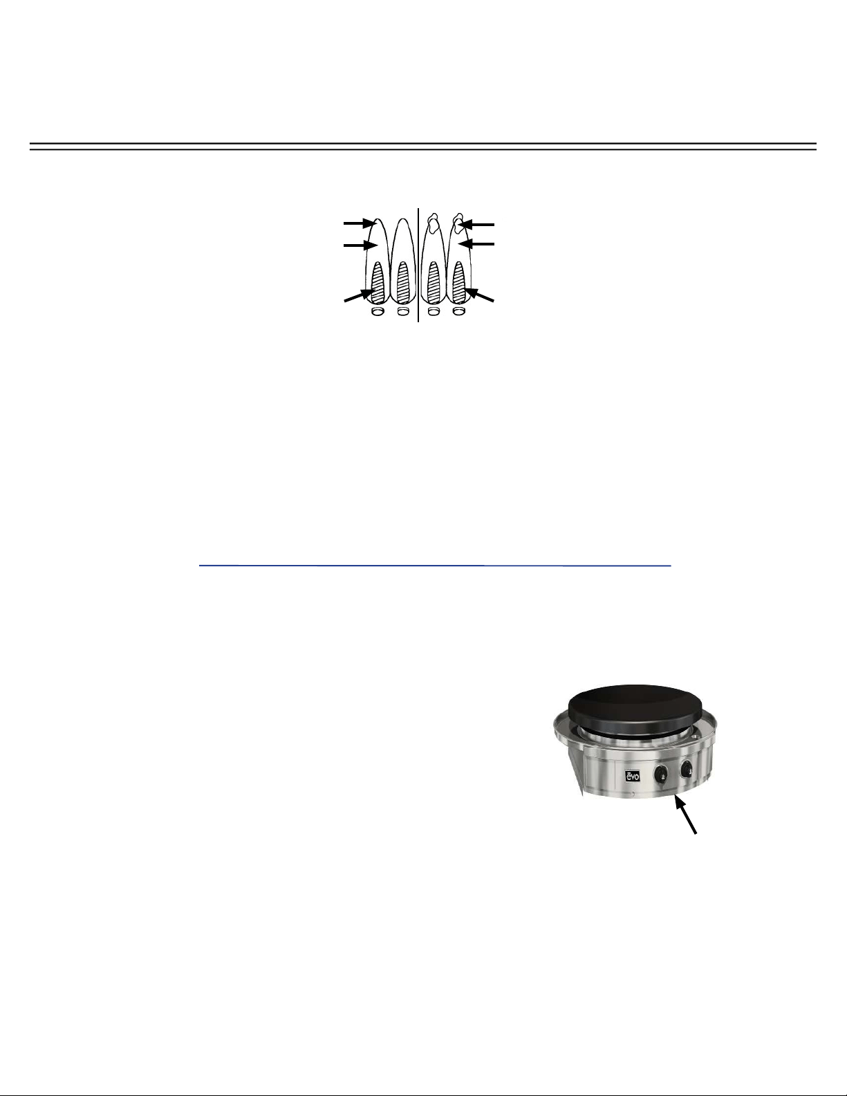
RECOGNIZING ABNORMAL GAS OPERATION
Any of the following are considered to be abnormal operation and may require servicing:
• Excessive yellow tipping of the burner fl ame (See diagram above).
• Sooting up of cooking utensils.
• Burners not igniting properly.
• Burners failing to remain alight.
• Gas valves, which are diffi cult to turn.
In case the appliance fails to operate correctly, contact the authorized service provider in your
area.
Right
Flame
Wrong
Flame
Dark Blue
Dark Blue
Light Blue
Light Blue
Yellow Tip
Excessive
Yellow Tipping
Remove the bottom
‘crescent-shaped’ access
panel just under the
front control panel to
access burner venturis, or
alternatively remove the
cooking surface and drip
pan to access the valve
cover located just above the
center control knob.
Checking Venturi Tubes:
A clogged venturi tube due to accumulated debris or lint
may cause improper burner performance and diffi culty
lighting your grill.
To check your venturi tubes:
• Remove the bottom ‘crescent-shaped’ access panel just
under the front control panel to access burner venturis,
or alternatively remove the cooking surface and drip pan
to access the valve cover located just above the center
control knob.
• Remove the cover and inspect the venturi for debris or
lint accumulation.
• Compressed air is the best method for removing these
obstructions.
OPERATOR INSTRUCTIONS
A f f i n i t y 3 0 G p
Evo, Inc., 20560 SW 115th Ave., Tualatin, OR 97062 USA
Phone 503.626.1802 | Fax 503.213.5869 | www.evoamerica.com | [email protected]
27
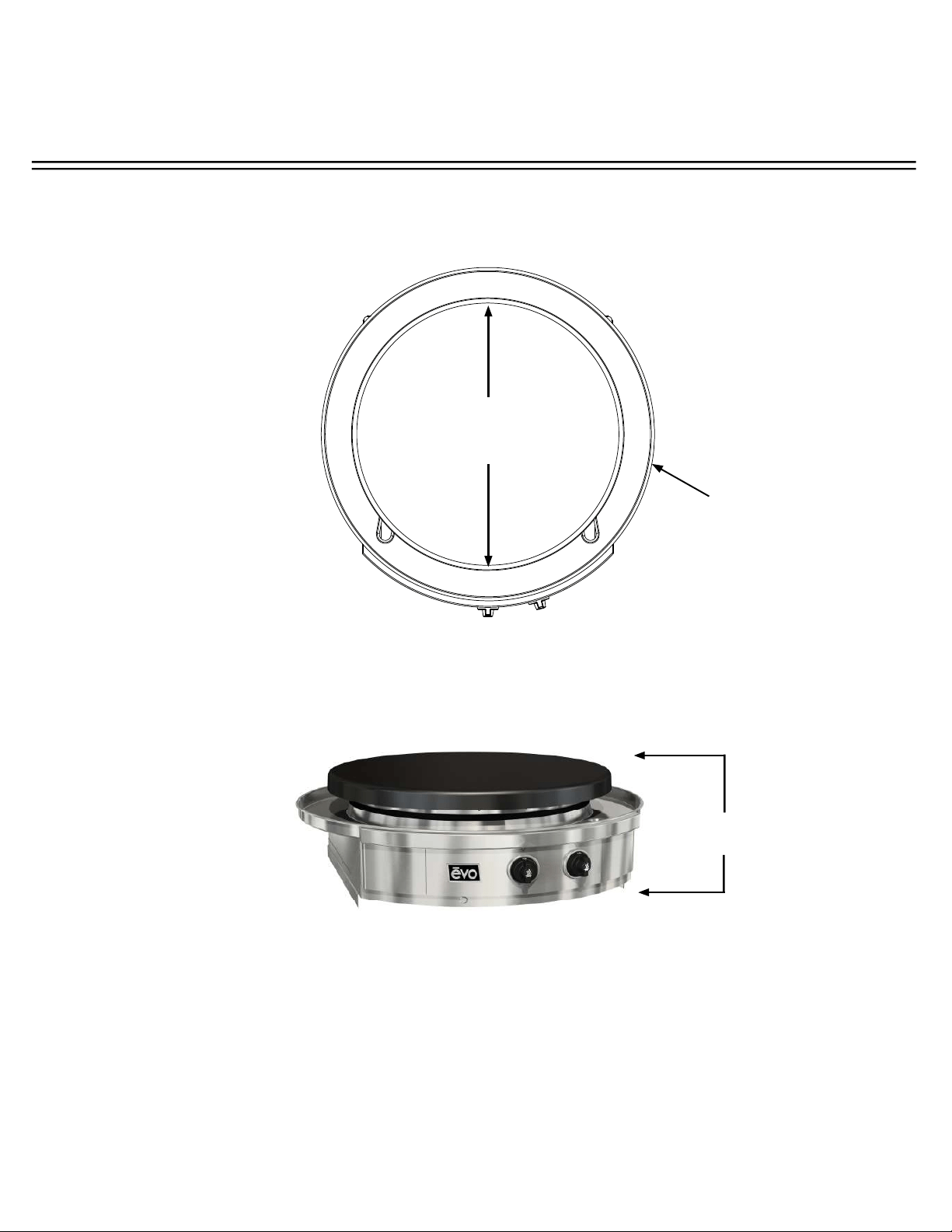
36 5/32”
914mm
30”
762mm
Diameter
11-7/32”
292mm
AFFINITY 30Gp DIMENSIONS

OPERATOR INSTRUCTIONS
A f f i n i t y 3 0 G p
Evo, Inc., 20560 SW 115th Ave., Tualatin, OR 97062 USA
Phone 503.626.1802 | Fax 503.213.5869 | www.evoamerica.com | [email protected]
28
Regular cleaning and care for your Evo Affi nity 30Gp cooktop will keep it looking and functioning its best.
The cook surface is designed to hold a fi ne layer of cooking oil creating a ‘seasoning’ on its surface. This
seasoning promotes a non-stick cooking surface and is easily maintained.
Caring for Evo’s cook surface is much like maintaining cast iron cookware. When the surface requires cleaning,
there are a few basic cleaning techniques to use. For quick and routine cleaning between preparations, a metal
spatula or scraper works for removing the majority of surface debris. For tougher areas or where sugars glaze
the cook surface, pour a small amount of vegetable oil on the soiled surface while the grill is warm and scrape the
debris away with a spatula. Heat the cook surface to a high temperature and allow the sticky debris to become
brittle. Once the debris is brittle, use the spatula or scraper to remove it. Afterwards wipe the cook surface with
vegetable oil again before cooking.
To condition the Evo cook surface you should use the grill cleaning kit supplied with your grill. The grill cleaning kit
contains a blue grill pad handle, grill cleaning screens, and grill grey polishing pads. Use the polishing pad after
the grill cleaning pads to achieve a smooth cooking surface for the most delicate foods and applications.
To use a grill cleaning screen: With a warm cook surface, place one gray polishing pad between the grill handle
base and the grill screen, so the grill screen makes direct contact with the cooking surface. Pour a small amount
of vegetable oil on the cook surface and scrub the surface in a circular motion. The gray polishing pad allows
excess oil to be absorbed and scours the cooking surface of carbonized debris. When fi nished scrubbing, wipe
the surface down with a paper towel or cotton terry cloth.
The stainless steel drip pan located just below the cook surface is designed to catch food debris and drippings
from the cook surface. We recommend cleaning the drip pan after your grill has cooled to prevent the possibility of
touching hot adjoining surfaces. The drip pan is easy to wipe out with soap and water using a kitchen sponge. For
added convenience, two removable stainless spill-over pans (ninth-pan size) are mounted inside the swing open
doors at right and left side of the front control panel for collecting drip pan debris and spill overs. These spillover
pans are easily washed by hand or in a dishwasher. Be sure to empty the spillover pans after every use, and at a
minimum, whenever they appear half full.
All the stainless steel components on your grill can be easily cleaned with soap and water and polished using
a stainless steel cleaner/polish. Stainless steel cleaner can be purchased from the Evo web site along with
replacement grill cleaning and polishing pads. The Evo web site address is: www.evoamerica.com.
Thank You For Cooking With Evo!
COOK SURFACE MAINTENANCE