Loading ...
Loading ...
Loading ...
IM-40MHH-02 Specifications subject to change without notice. 13
Install All Power, Interconnecting Wiring, and
Piping to the Indoor Unit
1. Run the interconnecting piping and wiring from the outdoor unit to
indoor unit.
2. Run the interconnecting cable through hole in wall (outside to
inside).
3. Lift the indoor unit into position and route piping and drain through
the hole in wall (inside to outside). Fit the interconnecting wiring
into back side of indoor unit.
4. Put the upper claw at back of indoor unit on upper hook of
Mounting Plate, move indoor unit from side to side to see that it is
securely hooked.
5. Open the indoor unit’s front panel by loosening the screws, which
provides a large space for wiring connection.
6. Open the wire box cover to connect the cable.
7. Pull the interconnecting wire up from back of indoor unit and
position in close to the terminal block on indoor unit.
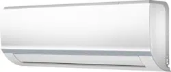
8. Push the lower part of indoor unit up on wall, then move indoor unit
from side to side, up and down to check if it is hooked securely (see
Fig. 22).
Fig. 22 — Indoor Unit Installation
9. Connect wiring from outdoor unit per connection diagram (see Fig.
18 and Fig. 19).
10. Replace the wire cover on the front of the unit, and the plastic panel
on the back.
Piping
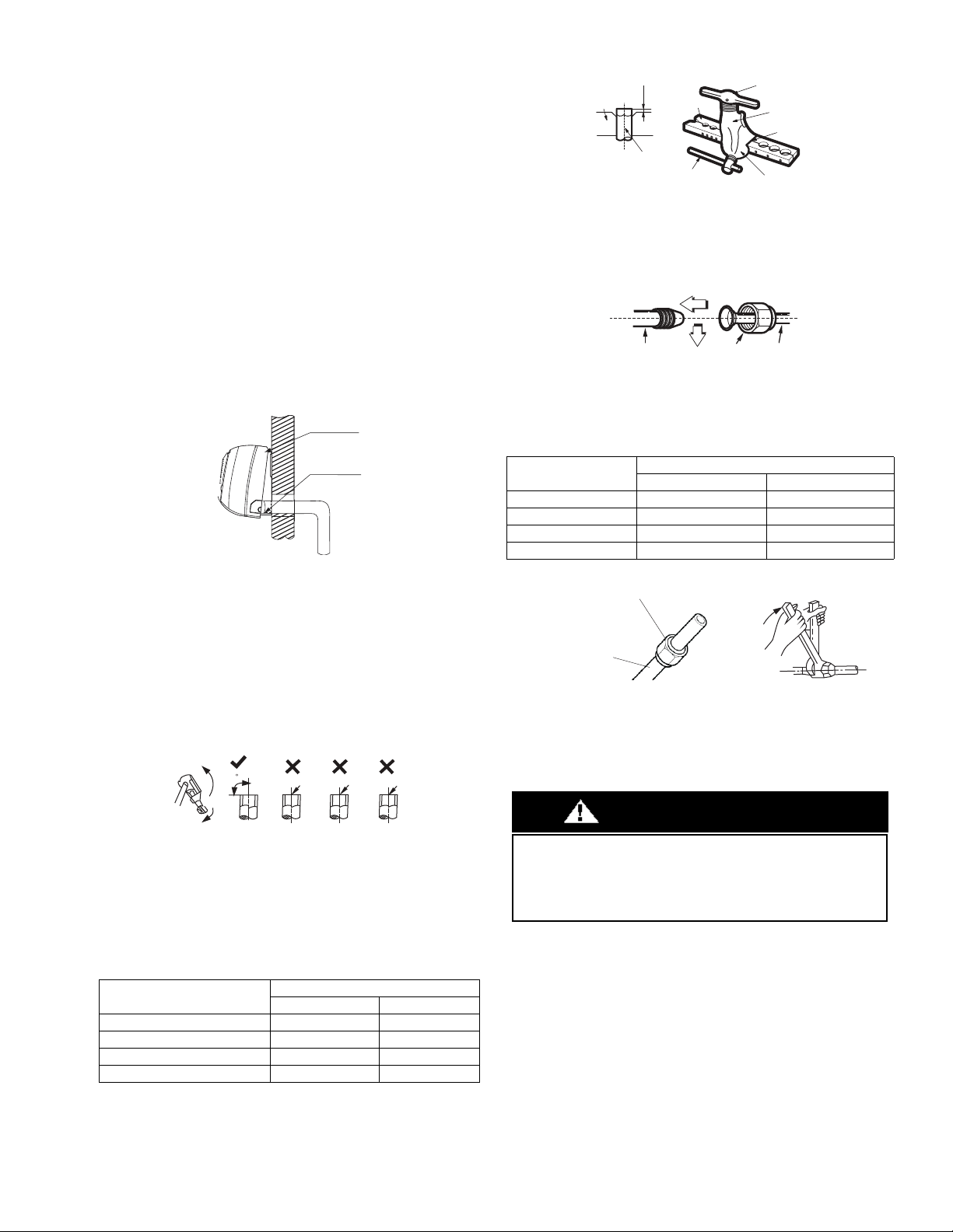
a. Cut the pipe, with a pipe cutter, at 90 degrees (see Fig. 23).
b. Remove the service connection, if provided with the unit.
Fig. 23 — Pipe Cutting
c. Remove all the burrs from the cut cross section of the pipe
avoiding any burrs inside the tubes.
d. Remove the flare nuts attached to the indoor and outdoor
units.
e. Install the correct size flare nut onto the tubing and make the
flare connection. Refer to Table 6 for the flare nut spaces.
Table 6 — Flare Nut Spacing
Fig. 24 — Flare Nut Spacing
f. Apply a small amount of refrigerant oil to the flare
connection on the tubing.
g. Align center of the pipes and/or service valve.
Fig. 25 — Align Pipe Center
h. Connect both the liquid and gas piping to the indoor unit
i. Tighten the flare nut using a torque wrench as specified in
Table 7.
Table 7 — Tightening Torque
Fig. 26 — Tighten the flare nut
For additional diagnostic information, refer to the Service Manual.
Refrigerant tubes and indoor coil should be evacuated using the
recommended deep vacuum method of 500 microns. The alternate
triple evacuation method may be used if the procedure outlined below
is followed. Always break a vacuum with dry nitrogen.
OUTER DIAM INCH (MM)
A INCH (MM)
MAX. MIN.
Ø 1/4” (6.35) 0.05 (1.3) 0.03 (0.7)
Ø 3/8” (9.52) 0.06 (1.6) 0.04 (1.0)
Ø 1/2” (12.7) 0.07 (1.8) 0.04 (1.0)
Ø 5/8” (15.88) 0.09 (2.2) 0.08 (2.0)
Upper hook
Lower hoo
k
Oblique
90
Roughness
Burr
PIPE DIAMETER
INCH (MM)
TIGHTENING TORQUE
Ft-lb N - m
Ø1/4” (6.35) 10 to 13 13.6 to 17.6
Ø3/8” (9.52) 24 to 31 32.5 to 42.0
Ø1/2” (12.7) 37 to 46 50.1 to 62.3
Ø5/8” (15.88) 50 to 60 67.7 to 81.3
Bar
Copper pipe
Clamp handle
Red arrow mark
Cone
Yoke
Handle
Bar
"A"
Indoor unit tubing Flare nut Piping
Flare nut
Coppe
r tube
UNIT DAMAGE HAZARD
Failure to follow this caution may result in equipment damage or
improper operation.
Never use the system compressor as a vacuum pump.
CAUTION
Loading ...
Loading ...
Loading ...