INSTALLATION AND OPERATION INSTRUCTIONS FOR W ALL-M OUNT
AND BUILT-IN UNITS
W M -FM L-26-3223-STL
W M -FM L-34-4023-STL
W M -FM L-48-5523-STL
W M -FM L-60-6623-STL
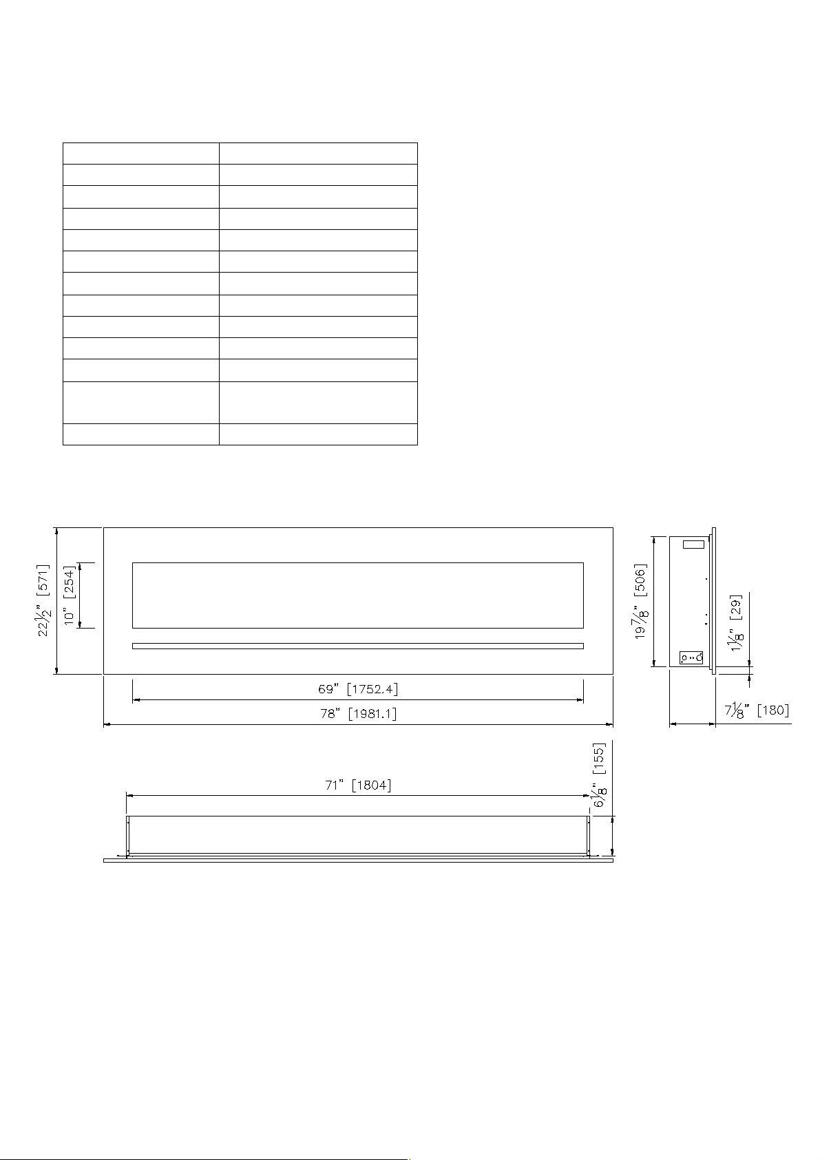
W M -FM L-72-7823-STL
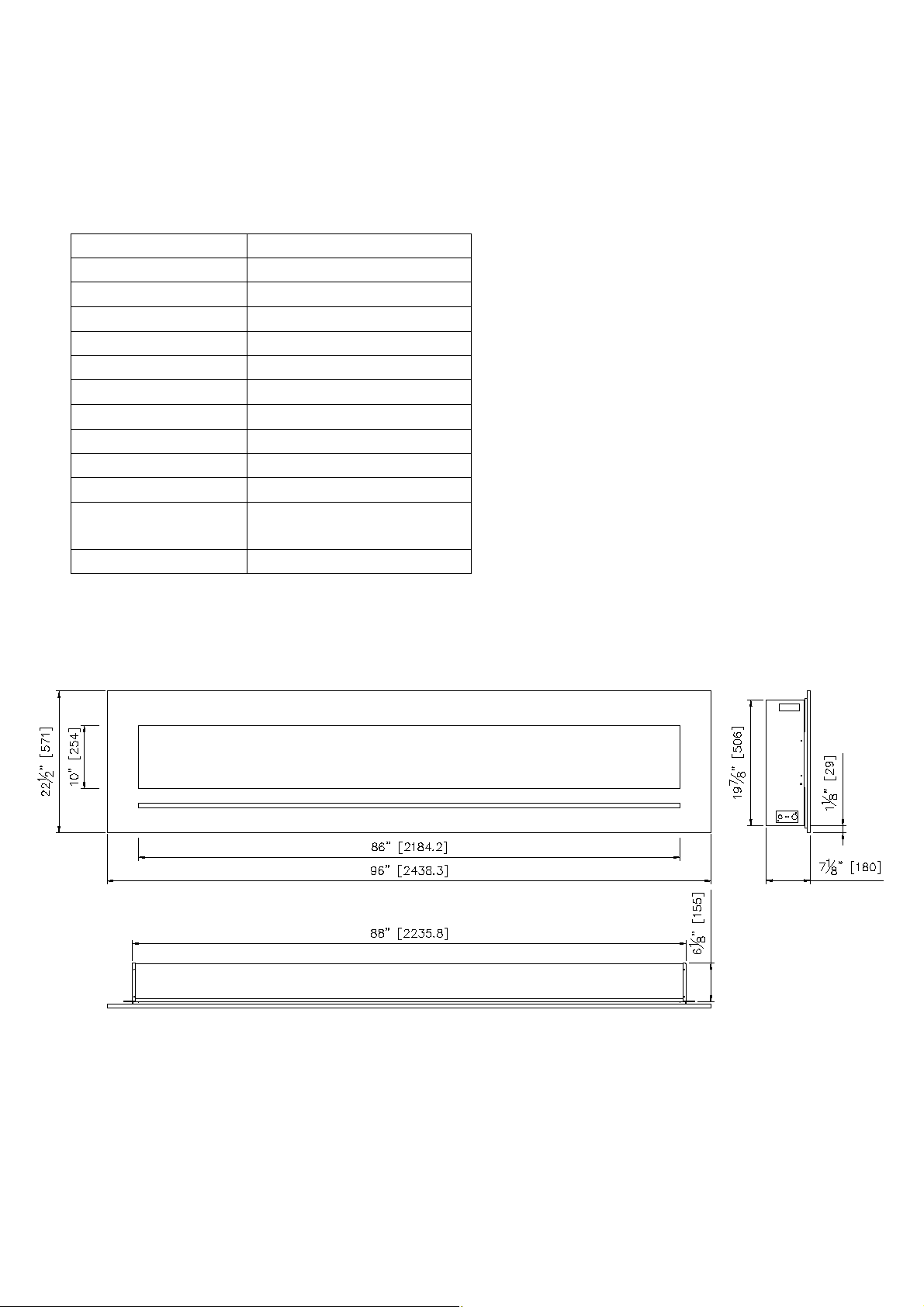
W M -FM L-88-9623-STL
SAFETY INFORM ATION
WARNING
If the information in these instructions are
not followed exactly, a fire or explosion
may result causing property damage,
personal injury or loss of life.
Do not store or use gasoline or other flammable vapors
and liquids in the vicinity of this or any other appliance.
INSTALLER: LEAVE THIS M ANUAL W ITH THE APPLIANCE.
CONSUM ER: RETAIN THIS M ANUAL FOR FUTURE REFERENCE.

2
TABLE OF CONTENTS
Please read and carefully follow all of the instruction found in this manual. Please pay special
att ent ion to the safety instructions provided in this manual. The instructions included here will assure
that you have many years of dependable and enjoyable service from your Serria Flame product.
IMPORTANT INSTRUCTIONS....................................................................................................................................3
UNPACKING AND TESTING APPLIANCE...............................................................................................................4
GROUNDING APPLIANCE.........................................................................................................................................4
LOCATING THE FIREPLACE.....................................................................................................................................4
WM-FML-34-4023-STL................................................................................................................................................6
WM-FML-48-5523-STL................................................................................................................................................7
WM-FML-60-6623-STL................................................................................................................................................8
WM-FML-72-7823-STL................................................................................................................................................9
WM-FML-88-9623-STL ..............................................................................................................................................10
REMOVING FRONT PANEL.....................................................................................................................................11
INSTALLATION-WALL MOUNT..............................................................................................................................12
INSTALLATION- BUILT-IN.......................................................................................................................................13
HARD- WIRE INSTALLATION.................................................................................................................................14
MEDIA OPTIONS.......................................................................................................................................................15
DECORATIVE MEDIA INSTALLATION..................................................................................................................15
OPERATION................................................................................................................................................................16
OPERATING WITH TOUCH PANEL .......................................................................................................................16
REMOTE CONTROL OPERATION...........................................................................................................................17
INSTALLING WALL THERMOSTAT........................................................................................................................18
REPLACEMENT PARTS............................................................................................................................................19
EXPLODED VIEW......................................................................................................................................................20
TRUBLE SHOOTING.................................................................................................................................................21
SERVICE HISTORY....................................................................................................................................................22
WARRANTY...............................................................................................................................................................23
WM-FML-26-3223-STL................................................................................................................................................5

3
IM PORTANT INSTRUCTIONS
Read all instructions before inst alling or using this heater.
2. Keep combustible mat erials, such as furnit ure, pillows, bedding, papers, clothes and curt ains at
least 3 feet from the front of the heater; keep them away from sides and rear as well.
3. Always unplug heater when it’s not in use.
4. Do not operat e the fireplace if it has a damaged cord or plug, after it has malfunctioned, or if the
unit has been dropped or damaged in any way.
5. Do not use the heat er outdoors.
6. This heat er is not intended for use in bathrooms, laundry areas and similar indoor locations.
Never place the heater where it may fall into a batht ub or other wat er containers.
7. Do not run the cord under carpeting. Do not cover the cord with throw rugs, runners or anyt hing
else. Arrange the cord away from traffic areas where it could not be tripped over.
8. To disconnect the heater, turn the controls to "OFF" before removing the plug from the out let.
9. Do not insert or allow foreign objects to ent er any ventilat ion or exhaust opening, as this may
cause an electric shock, fire or damage to the heater.
10. To prevent a possible fire, do not block air int akes in any manner.
11. A heat er has hot and arcing or sparking part s inside. Do not use it in areas where gasoline, paint
or flammable liquids are used or st ored.
12. Use this heater only as described in this manual. Any other use not recommended by the
manufacturer may cause fire, electric shock or injury to persons.
13. Avoid the use of an extension cord because the ext ension cord may overheat and cause a fire.
14. Always use properly grounded fused and polarized out let s.
15. Always use ground fault prot ection where it is required by electrical codes.
16. Always disconnect the pow er before performing any cleaning, maintenance or relocation of the
heater.
17. To prevent a possible fire, do not burn wood or other mat erials in this heater.
18. To prevent electric shock or fire, always use a certified electrician, should new circuit s or out let s
be required.
When transporting or st oring the heater, keep it in a dry place, free from excessive vibrat ion.
1.
19.
4
UNPACKING AND TESTING APPLIANCE
Carefully remove the appliance from the box. Prior to installing the appliance, test to make
sure the appliance operates properly by plugging the power supply cord into a conveniently
located 120 Volt grounded outlet.
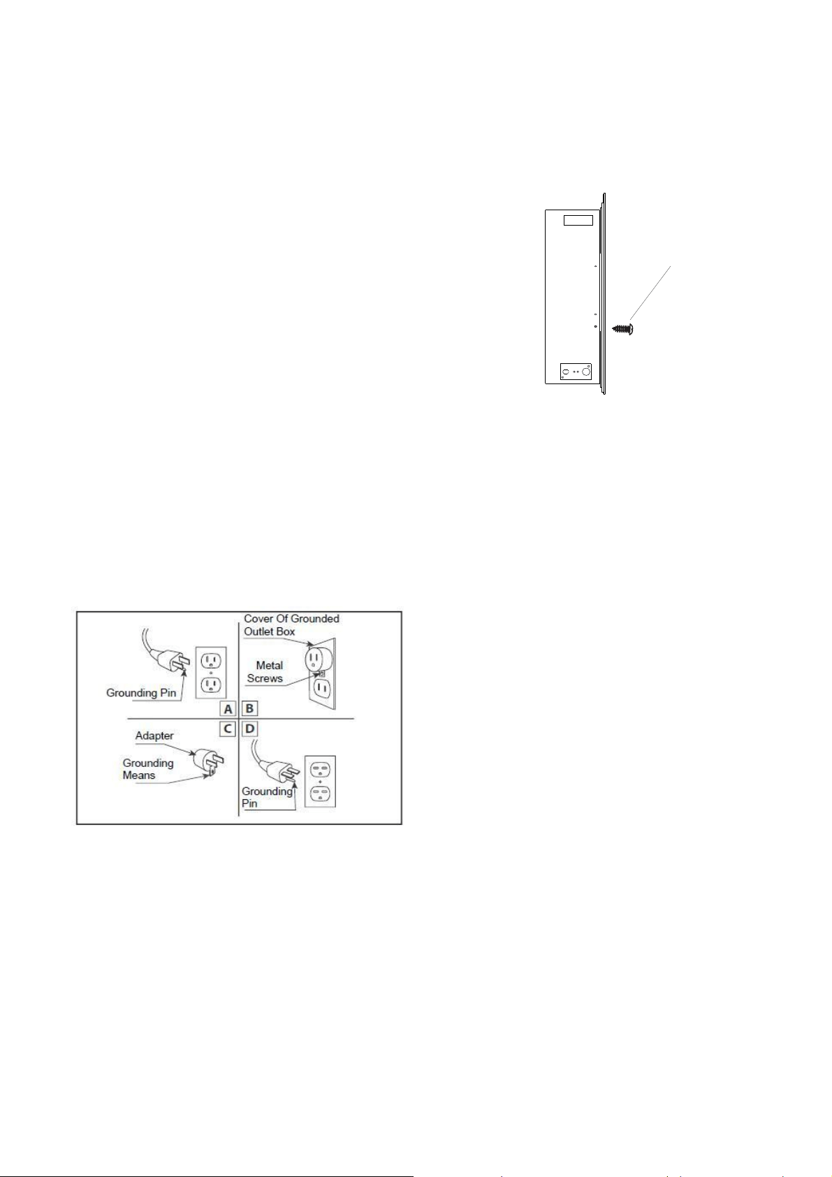
GROUNDING APPLIANCE
This appliance is for use on 120 Volts. The cord has a plug as shown in (A). An adapter as
shown in (C) is available for connecting three-blade grounding type plugs to two-slot
receptacles. The green grounding lug extending from the adapter must be connected to a
permanent ground such as a properly grounded outlet box. The adapter should not be used if
a three-slot grounded receptacle is available.
To disconnect appliance, turn controls to off, then remove plug from outlet.
LOCATING THE FIREPLACE
Plan where to locate and frame the fireplace. This will save time and money later when you
install the fireplace. Before installation consider the following:
1. Where the fireplace is located must allow for wall and ceiling clearances (see
INSTALLATION-WALL MOUNT)
2. Consider a location where the fireplace screen will not be exposed to direct sunlight from
windows or doors.
3. A 15 ampere, 120 Volt, 60 Hz branch circuit with proper ground must be available at the
location. Preferably a dedicated branch circuit should be provided to avoid circuit
breakers to trip or fuses to blow.
Screw
There are two screws on each side to fix the front panel.
Please see the figure right side.
TAKE OUT THIS SCREW ON EACH SIDE
before you take off the front panel.
5
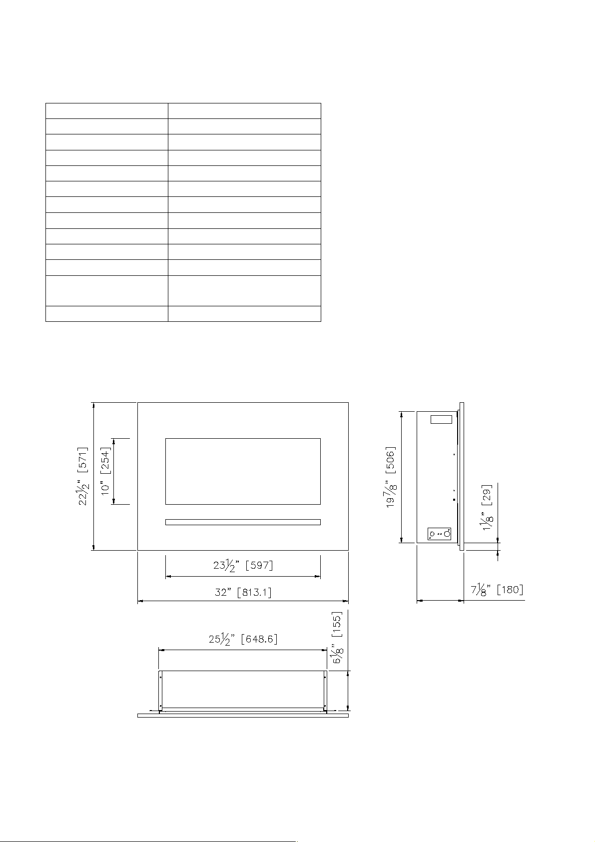
W M -FM L-26-3223-STL
Descript ion Built-in or Wall M ount Appliance
Voltage 120V AC 60Hz
Wat ts 1500W M ax
NO HEATER 25W
M OTOR HEATER 19W
Appliance Widt h 25 1/ 2” or 64.9 cm
Appliance Height 19 7/ 8” or 50.6 cm
Appliance Dept h 6 1/ 8” or 15.5 cm
Gross Weight 52.8 lbs or 24 kg
Plug Location Left side
Cord Length 70 7/ 8 ” or 180 cm
Rough Wall Opening
Size
27”× 20 1/ 2“ or
68.60 cm× 52 cm
BTU 4800
This appliance has been tested in
accordance with the UL Standard 2021
for fixed and location dedicated
electric room appliances in the Unit ed
St ates and Canada. If you need
assistance during inst allation, please
contact your local dealer.
NOTE: This appliance must be
electrically wired and grounded in
accordance with local codes. In the
absence of local codes, use the
current CSA C22.1 Canadian Electrical
Code in Canada or the ANSI/ NFPA 70
National Electrical Code in the United
States.
6
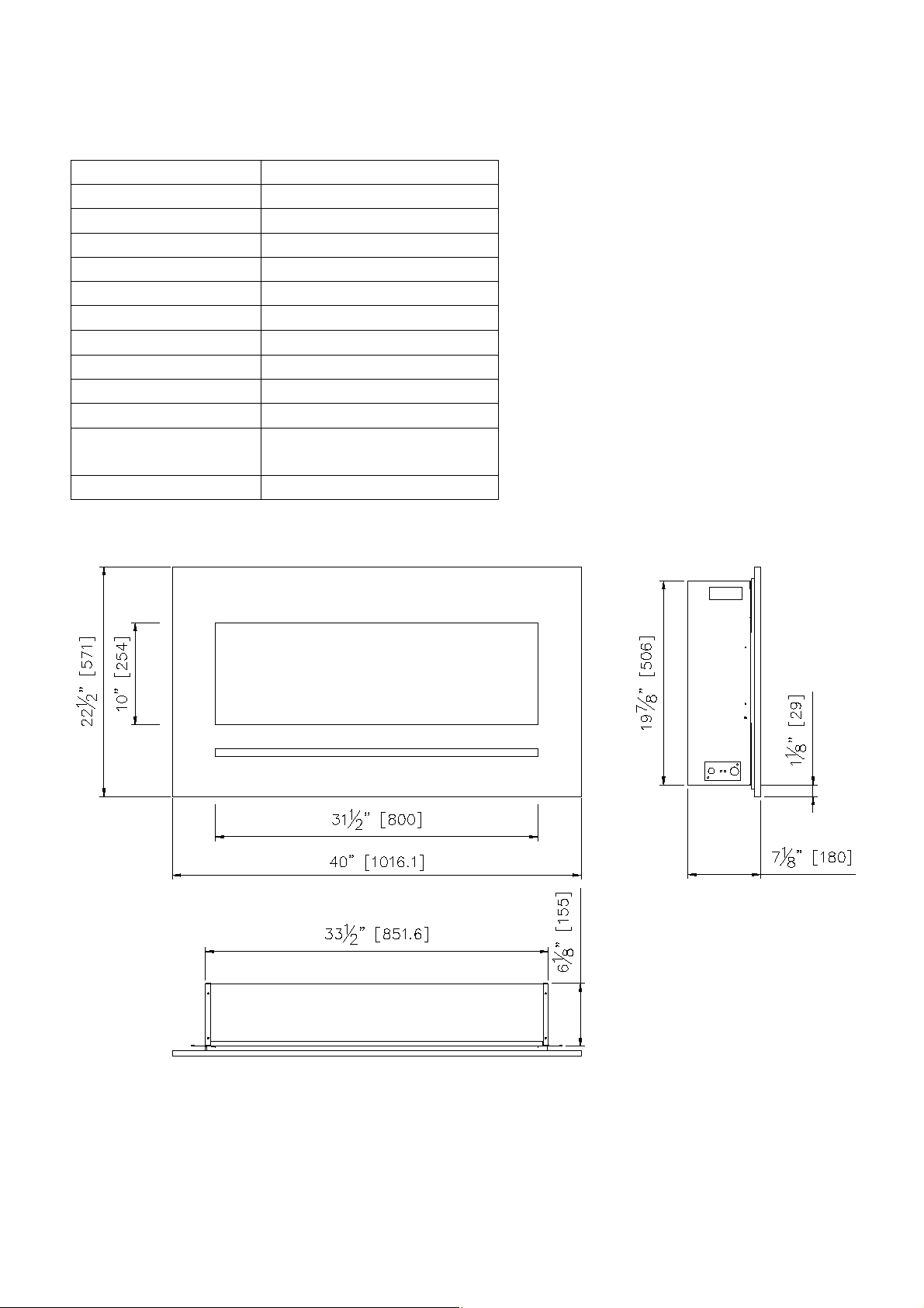
W M -FM L-34-4023-STL
Descript ion Built-in or Wall M ount Appliance
Voltage 120V AC 60Hz
Wat ts 1500W M ax
NO HEATER 25W
M OTOR HEATER 19W
Appliance Widt h 33 1/ 2” or 85.2 cm
Appliance Height 19 7/ 8” or 50.6 cm
Appliance Dept h 6 1/ 8” or 15.5 cm
Gross Weight 63.1 lbs or 28.7 kg
Plug Location Left side
Cord Length 70 7/ 8 ” or 180 cm
Rough Wall Opening
Size
35”× 20 1/ 2“ or
88.9 cm ×52 cm
BTU 4800
This appliance has been tested in
accordance with the UL Standard 2021
for fixed and location dedicated electric
room appliances in the United Stat es and
Canada. If you need assist ance during
installation, please cont act your local
dealer.
NOTE: This appliance must be
electrically wired and grounded in
accordance with local codes. In the
absence of local codes, use the current
CSA C22.1 Canadian Electrical Code in
Canada or the ANSI/ NFPA 70 National
Electrical Code in the United States.
7
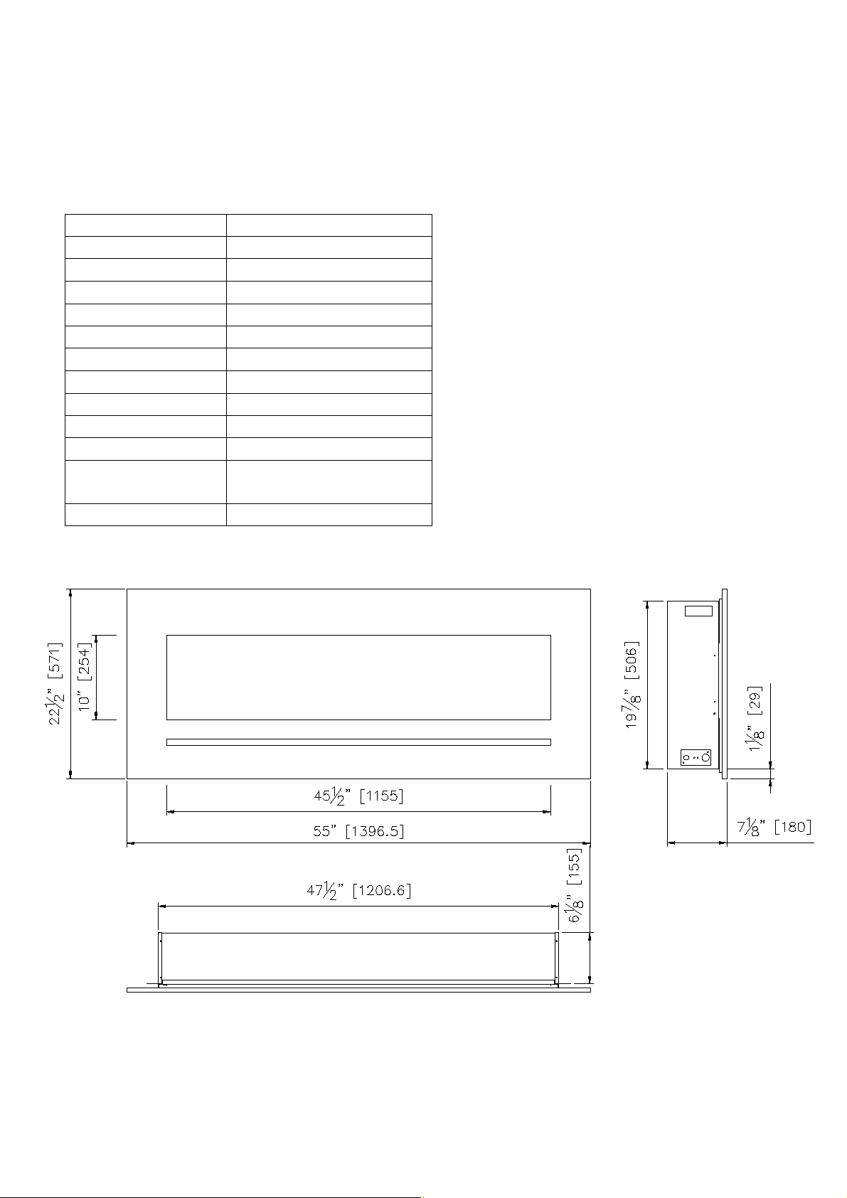
W M -FM L-48-5523-STL
Descript ion Built-in or Wall M ount Appliance
Voltage 120V AC 60Hz
Wat ts 1500W M ax
NO HEATER 25W
M OTOR HEATER 19W
Appliance Widt h 47 1/ 2” or 120.6 cm
Appliance Height 19 7/ 8” or 50.6 cm
Appliance Dept h 6 1/ 8” or 15.5 cm
Gross Weight 81 lbs or 36.7 kg
Plug Location Left side
Cord Length 70 7/ 8 ” or 180 cm
Rough Wall Opening
Size
49”× 20 1/ 2“ or
124.5 cm× 52 cm
BTU 4800
This appliance has been tested in
accordance with the UL Standard 2021 for
fixed and location dedicated electric room
appliances in the United Stat es and Canada.
If you need assist ance during installat ion,
please contact your local dealer.
NOTE: This appliance must be electrically
wired and grounded in accordance with
local codes. In the absence of local codes,
use the current CSA C22.1 Canadian
Electrical Code in Canada or the ANSI/ NFPA
70 National Electrical Code in the United
States.
8
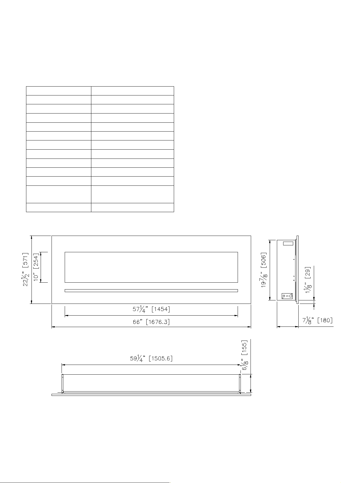
W M -FM L-60-6623-STL
Descript ion Built-in or Wall M ount Appliance
Voltage 120V AC 60Hz
Wat ts 1500W M ax
NO HEATER 25W
M OTOR HEATER 19W
Appliance Widt h 59 1/ 4” or 150.6 cm
Appliance Height 19 7/ 8” or 50.6 cm
Appliance Dept h 6 1/ 8” or 15.5 cm
Gross Weight 97.2lbs or 44.2kg
Plug Location Left side
Cord Length 70 7/ 8 ” or 180 cm
Rough Wall Opening
Size
60 5/ 8”× 20 1/ 2“ or
154 cm× 52cm
BTU 4800
This appliance has been tested in
accordance with the UL Standard 2021 for
fixed and location dedicated electric room
appliances in the United Stat es and Canada.
If you need assist ance during installat ion,
please contact your local dealer.
NOTE: This appliance must be electrically
wired and grounded in accordance with
local codes. In the absence of local codes,
use the current CSA C22.1 Canadian
Electrical Code in Canada or the ANSI/ NFPA
70 National Electrical Code in the United
States.
9
W M -FM L-72-7823-STL
Descript ion Built-in or Wall M ount Appliance
Voltage 120V AC 60Hz
Wat ts 1500W M ax
NO HEATER 25W
M OTOR HEATER 19W
Appliance Widt h 71” or 180.4 cm
Appliance Height 19 7/ 8” or 50.6 cm
Appliance Dept h 6 1/ 8” or 15.5 cm
Gross Weight 113.3lbs or 51.5kg
Plug Location Left side
Cord Length 70 7/ 8 ” or 180 cm
Rough Wall Opening
Size
72 1/ 2”× 20 1/ 2“ or
184 cm× 52 cm
BTU 4800
This appliance has been tested in
accordance with the UL Standard 2021 for
fixed and location dedicated electric room
appliances in the United Stat es and
Canada. If you need assist ance during
installation, please cont act your local
dealer.
NOTE: This appliance must be electrically
wired and grounded in accordance with
local codes. In the absence of local codes,
use the current CSA C22.1 Canadian
Electrical Code in Canada or the
ANSI/ NFPA 70 National Electrical Code in
the United States.
10
W M -FM L-88-9623-STL
Descript ion Built-in or Wall M ount Appliance
Voltage 120V AC 60Hz
Wat ts 1500W M ax
NO HEATER 25W
M OTOR HEATER 19W
Appliance Widt h 88” or 223.6 cm
Appliance Height 19 7/ 8” or 50.6 cm
Appliance Dept h 6 1/ 8” or 15.5 cm
Gross Weight 138.6lbs or 63kg
Plug Location Left side
Cord Length 70 7/ 8 ” or 180 cm
Rough Wall Opening
Size
89 1/ 2”× 20 1/ 2“ or
227.3 cm× 52 cm
BTU 4800
This appliance has been tested in
accordance with the UL Standard 2021 for
fixed and location dedicated electric room
appliances in the United Stat es and Canada.
If you need assist ance during installat ion,
please contact your local dealer.
NOTE: This appliance must be electrically
wired and grounded in accordance with
local codes. In the absence of local codes,
use the current CSA C22.1 Canadian
Electrical Code in Canada or the ANSI/ NFPA
70 National Electrical Code in the United
States.
11
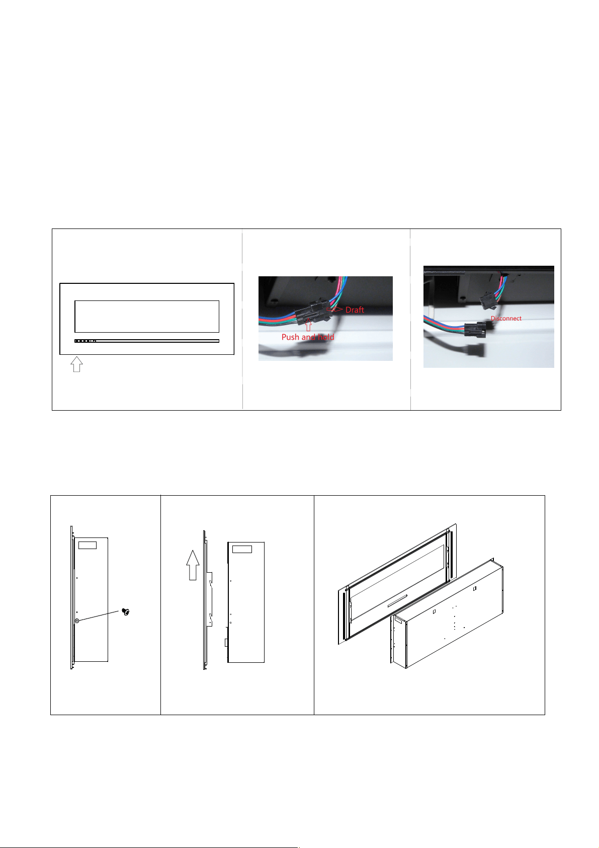
REMOVING FRONT PANEL
Models WM-FML-26-3223-STL, WM-FML-34-4023-STL, WM-FML-48-5523-STL, WM-
-FML-60-6623-STL each have 2 screws that secure the front panel in place. Models WM-FML-
-72-7823-STL and WM-FML-88-9623-STL have four screws that secure the front panel in
Two people are required for the installation process.
1. The back-lighting LED is located on the back of the front panel. Before removing the front
panel you must unplug the back-lighting from the unit. This plug is located at the bottom left
hand side behind the front panel.
2. The screws are located on the sides of the unit. Once located, unscrew the two or four screws.
You can then lift the front panel from the 4 shoulder posts on the sides of the unit and remove the
front panel.
3. To replace the front panel, lift onto the 4 shoulder posts. For a Wall Mount installation replace
the two or four screws to secure the glass. For Flush Mount installs it is not possible to replace
the screws.
Location of the back-lighting plug Unplug the back-lighting
Screw locations on uint
Lift the front panel from shoulder
place.
posts.
12
INSTALLATION-W ALL M OUNT
1. Select a location that is not prone to
moisture and is located at least 0.91 m or 3
feet away from combustible mat erials such
as curtains or drapes, furnit ure, bedding,
paper, et c.
2. Referring to Fig. 1 below select a suit able
position in which to mount the heater
horizont ally – use a spirit level to achieve
this.
3. Check the wall to ensure there is no wiring,
pipe wires et c in the area to be drilled. Drill
8 or more holes (8mm diameter & 40mm
depth) using a suitable size drill and put the
wall plugs into the holes.
4. Remove mount ing plate from the back of the appliance
by removing the tw o scew s as shown in Fig. 2.
5. Referring to Fig. 3, secure the mount ing plate to
the wall.
6. Secure the fireplace to the wall using a screw . Fig. 4.
W arning!
Be sure that the bolts have been fixed
firmly enough to withstand the weight
!
Fig. 1
Fig. 2
Fig.3
Fig. 4
Remove mounting plate from the back of the appliance by
13
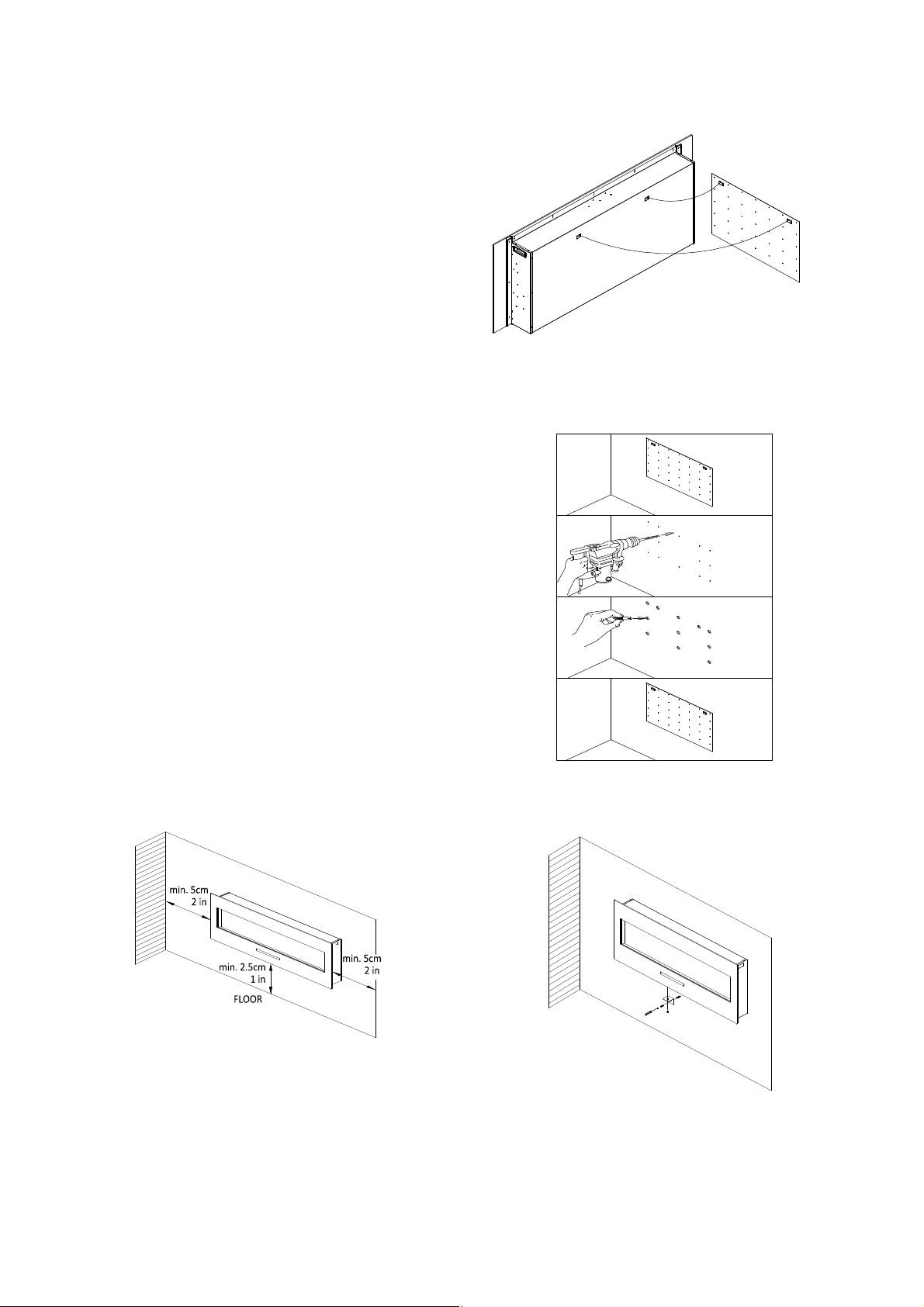
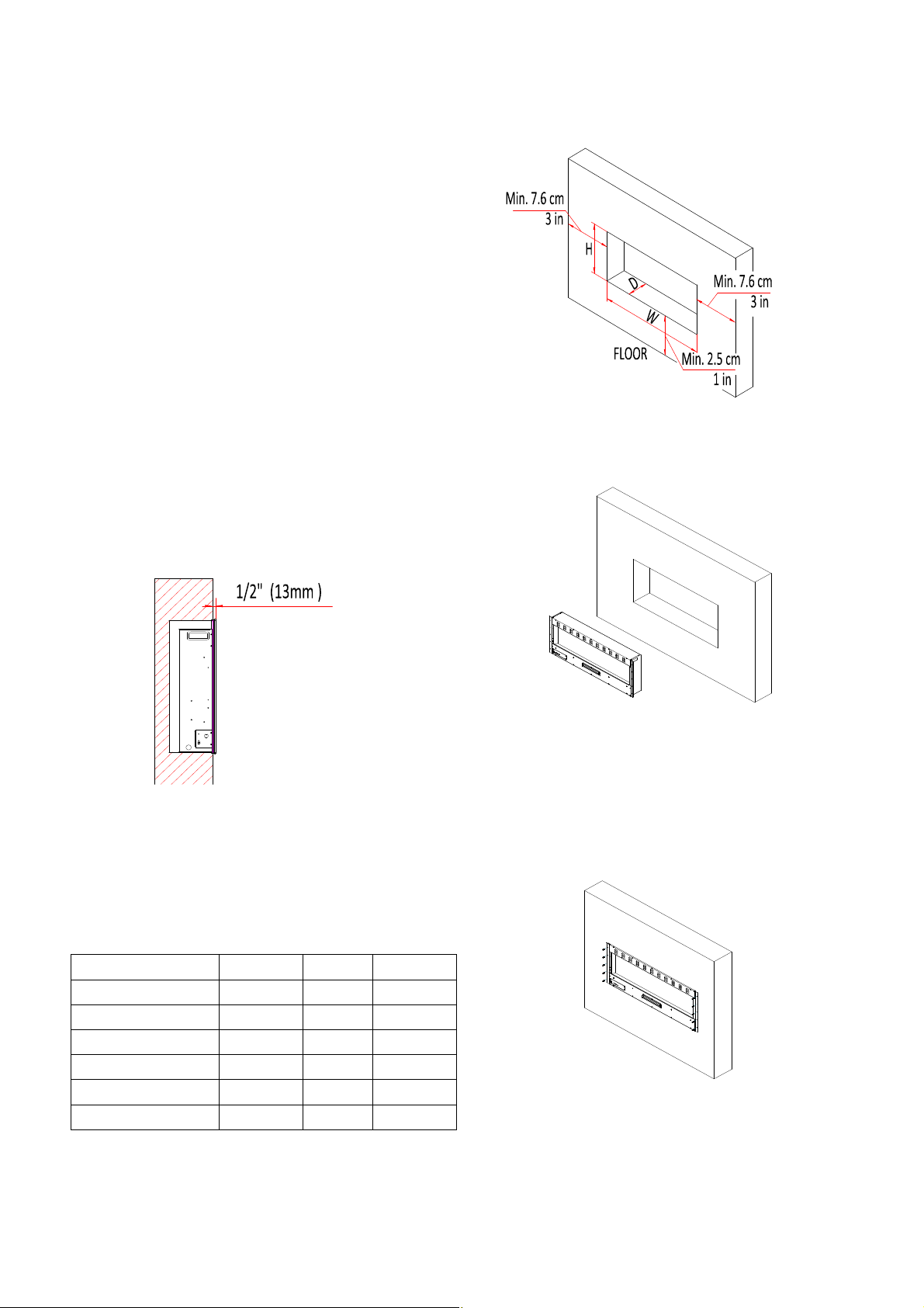
INSTALLATION- BUILT-IN
1. Select a location that is not prone to
moisture and is located at least 0.91m or 3
feet away from combustible mat erials such
as curtains or drapes, furnit ure, bedding,
paper, et c.
2. M ark the desired location on the floor and
store appliance in a safe, dry and dust free
location.
3. Prepare a wall with a framed opening to
accommodat e the size of your unit. Leave at
least 1/ 4 ” (6 mm) around the edge of the
appliance. Any new wiring must be done in
compliance with local and national codes
and other applicable regulat ions.
Note: Fireplace must st ick out of the wall a
minimum of 1/ 2 ” or 1.5 cm.
Prior to installing the appliance, test to make
sure the appliance operates properly by
plugging the power supply cord into a
conveniently located 120 Volt grounded
outlet.
The rough wall opening size of the fireplace:
W(“) D(“) H(“)
WM -FM L-26-3223-STL
27 6 1/ 2 20 1/ 2
WM -FM L-34-4023-STL
35 6 1/ 2 20 1/ 2
WM -FM L-48-5523-STL
49 6 1/ 2 20 1/ 2
WM -FM L-60-6623-STL
60 5/ 8 6 1/ 2 20 1/ 2
WM -FM L-72-7823-STL
72 1/ 2 6 1/ 2 20 1/ 2
WM -FM L-88-9623-STL
89 1/ 2 6 1/ 2 20 1/ 2
1. Take the front panel off from the unit. Put the
brackets on the both sides and top of the fireplace
as shown blew.
2. Lift fireplace and insert into opening.
3. M ake sure that the power supply port is not
behind the wall.
4. Level the fireplace.
5. Drive mount ing screws into the mounting
brackets on the unit and the wall st uds.
6 Replace the front panel and plug in back-.
-lighting LED. See page 11.
14
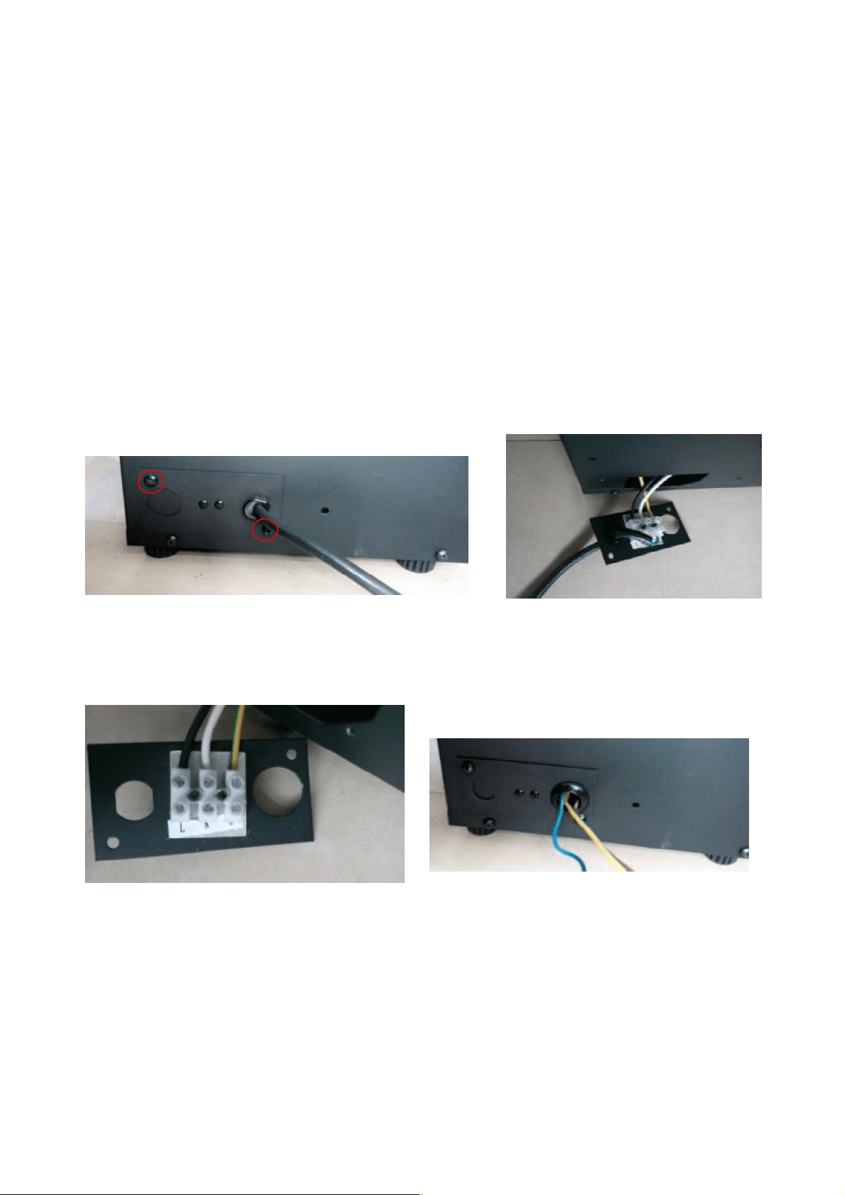
HARD- WIRE INSTALLATION
Turn off the appliance complet ely and let cool before servicing. Only a qualified service person
should service and repair this electric appliance.
If it is necessary to hard wire this appliance, a qualified electrician must remove the cord connection,
and wire the appliance directly to the household wiring.
This appliance must be electrically connected and grounded in accordance with local codes, if hard
wired. In the absence of local codes, use the current CSA C22.1 CANADIAN ELECTRICAL CODE in
Canada or the current ANSI/ NFPA 70 NATIONAL ELECTRICAL CODE in the United Stat es.
1. Remove the cover plate from the left side of the appliance by removing the tw o screws, as
shown below. Unscrew and remove pow er cord.
2. Att ach the wiring to the junction block. Please make sure the live wire goes into the “L”, the
neutral wire into “N” and the ground wire into “G”.
3. Put the plate back and screw back.
15
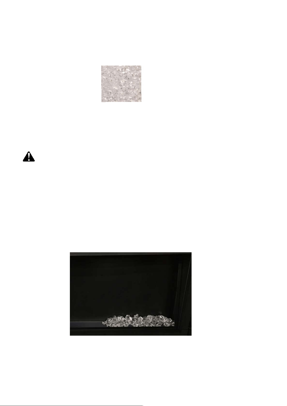
M EDIA OPTIONS
Clear
DECORATIVE MEDIA INSTALLATION
Installing the decorative media
Pour the fire glass media into the tray. Feel free to use any combination of fire glass
media that you find most appealing. Put back the front panel after you finish installing
the decorative media.
The only media that comes with this version is ‘Clear decorative media’. Consumers
may purchase optional decorative media if they choose. See dealer for more details.
Removing the front panel
NOTE:Please unplug the power cord before you install the decorative media.
Remove the screws from both sides of the unit to take off the surround. It is recommended that
two people lift the surround away from the unit.
16
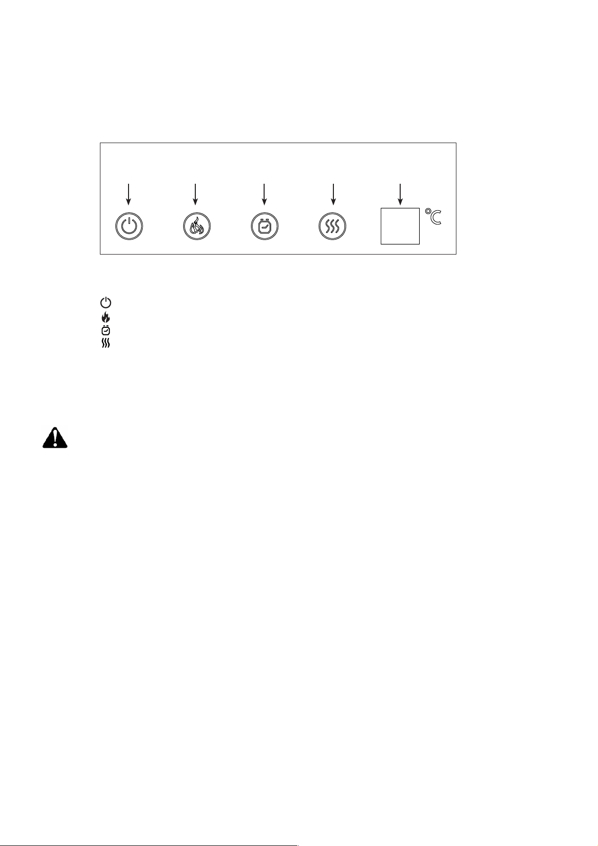
Operating with Touch Panel
The unit can be controlled by either the touch panel controls which are located on the left side of the front
panel or the remote control.
1. Press “ ” to turn on and off the appliance.
2. Press “ ” multiple times to adjust between mid, low, on/off, or high brightness options
3. Press “ ” multiple times to set operating duration to 30 min, 1h, 2h, 3h, 4h, 5h, 6h, 7h, 8h, or off.
4. Press “ ” multiple times to set ambient temperatures at
Whensettingthetemperature,thenumberwillash.
Note: The touch panel buttons will glow when pressed. The light fades in 5 seconds after pressing.
ON/OFF
Power
Flame Timer Heater Indicator
18℃(64.4℉),
19℃
(
66.2℉
)
, 20℃
(
68
℉
)
,
21℃
(
69.8
℉
)
,
22℃(71.6
℉), 23℃(73.4℉), 24℃(75.2℉),
25℃(77℉), 26℃(78.8℉), 27℃(80.6℉),
28℃(82.4
℉
),
ON or OFF.
NOTE:Please unplug the power cord if you will not use the fireplace for a long time.
17
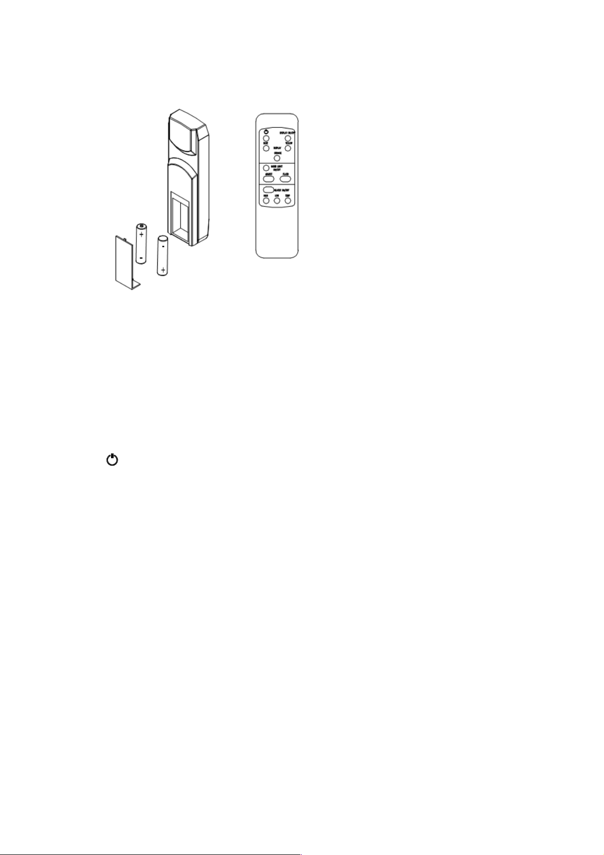
REM OTE CONTROL OPERATION
For remot e to function make sure the heater is plugged in and main power sw itch located on the
bot tom left hand side is at position I.
When operating the remot e make sure you point the remote to the cent re of the fireplace and make
sure each time you press the but ton the buzzer inside the unit will beep once. It takes some time for
the receiver to respond to the transmit ter. Do not PRESS the but tons more than once within two
seconds for correct operation.
Power on butt on: The power-on but ton at top left corner of the remot e is the main ON/ OFF
pow er but ton. This will turn off all the functions and the fireplace will be in st andby mode.
DISPLAY ON/ OFF button: Sw itching the fireplace flame and tray light ON/ OFF. It has functions of
sett ing memory.
DISPLAY BLUE button: Adjust the blue color brightness of flame and tray.
DISPLAY YELLOW button: Adjust the yellow color brightness of flame and tray.
DISPLAY ORANGE button: Adjust the orange color bright ness of flame and tray.
M OOD LIGHT ON/ OFF button: Sw itching the mood light ON/ OFF.
ADJUST button: Swit ching the color of the mood light.
FLASH button: Swit ches the mood light into flash mode, this cycles through all mood light colors.
HEATER ON/ OFF button: Sw itching the heat er ON/ OFF. It has functions of setting memory.
HIGHT button: Press the high butt on to swit ch the heat er to high heat sett ing 1500W.
LOW button: Press the low but ton to sw itch the heater to low heat sett ing 750W.
TEM P. button: Press the TEM P. but ton mult iple times to set ambient temperat ure at
Whensettingthetemperature,thenumberwillash.
18℃(64.4℉),
19℃
(
66.2℉
)
, 20℃
(
68℉
)
,
21℃
(
69.8℉
)
,
22℃(71.6
℉), 23℃(73.4℉), 24℃(75.2℉),
25℃(77℉),
26℃(78.8℉), 27℃(80.6℉),
28℃(82.4
℉
).
18
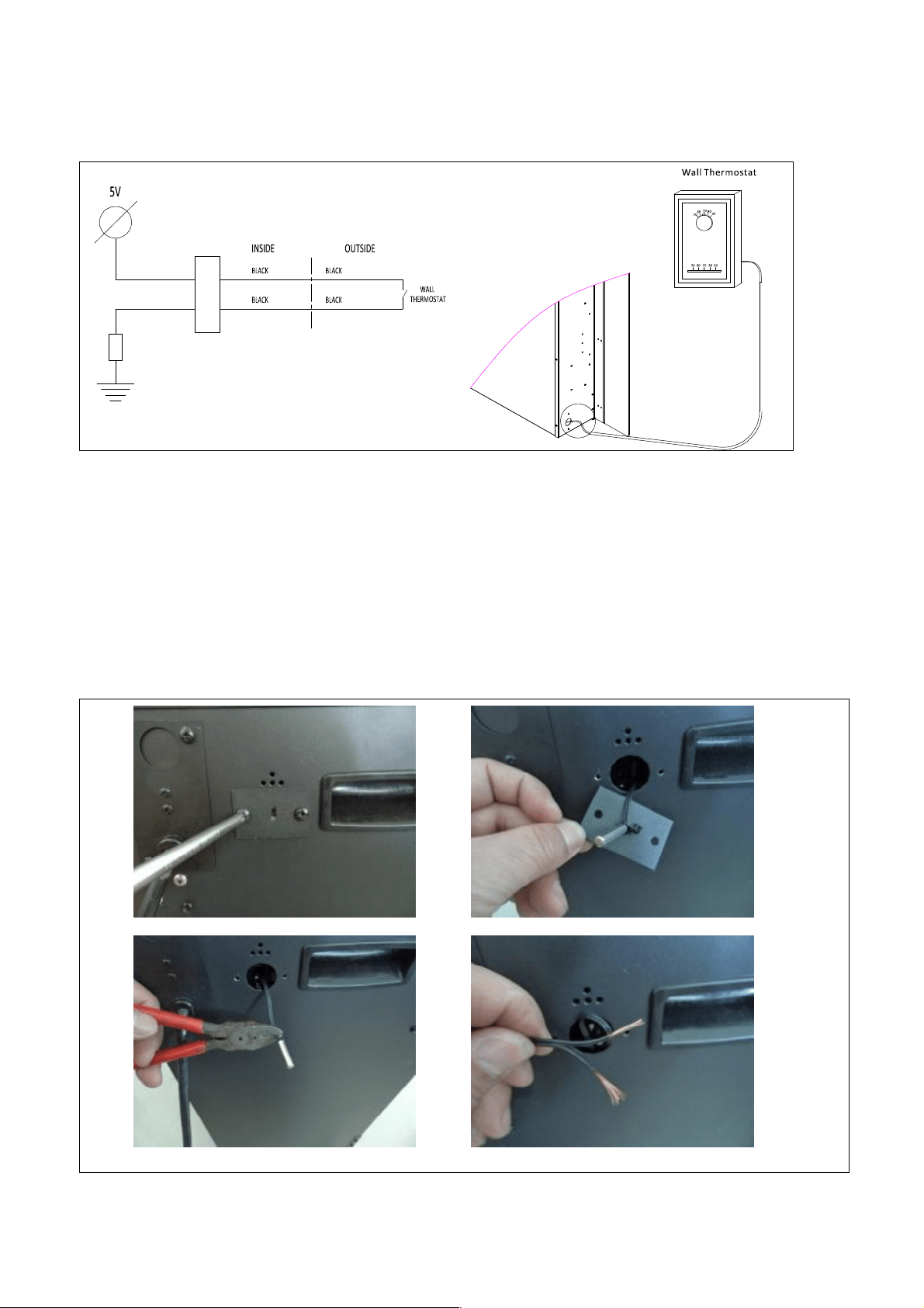
INSTALLING WALL THERM OSTAT
W ALL THERM OSTAT W IRING DIAGRAM S
NOTE: THE W ALL THERM OSTAT WILL WOKE WHEN THE HEATER ON TEM P. SETTING. PLEASE
REFER TO THE M ANUAL CONTROL AND THE REM OTE CONTROL.
W ire the wall thermostat prior to installing the fireplace.
W ALL THERM OSTAT W IRING(24 VAC)
Install W all Thermostat per instructions provided with kit and per the following information:
1. Turn off circuit breaker.
2. Remove cover plate located on the left side of appliance.
3. Pull the wire out and cut the inside thermostat . Connect the wires to the wall thermost at as
shown below. Follow instructions provided wit h wall swit ch kit.
19
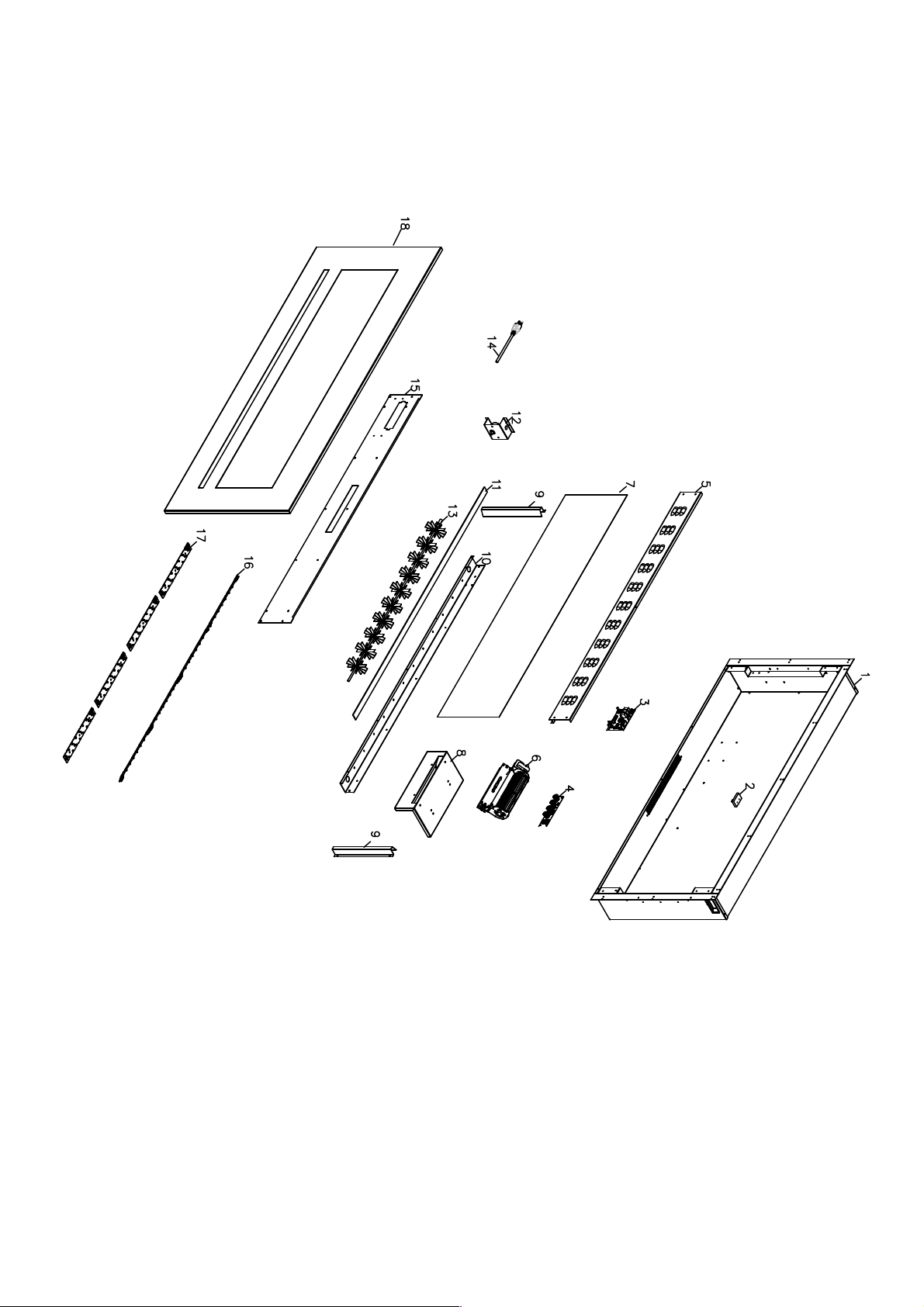
REPLACEM ENT PARTS
PART NUM BER
NO
WM -FM L-26-
3223-STL
WM -FM L-34-
4023-STL-
WM -FM L-48-
5523-STL
WM -FM L-60-
6623-STL
WM -FM L-72-
7823-STL
WM -FM L-88-
9623-STL
DESCRIPTION
QTY.
1 FIREPLACE BOX 1
2 301506 REM OTE RECEIVER 1
3 601095D CIRCUIT BOARD 1
4
5
601300C TOUCH PANEL 1
6
TOP PANEL 1
7
602082
BLOWER AND HEATER
ASSEM BLY
1
8
1070117 1070117 1070117 1070117
BACK BLACK PLASTIC GLASS
1
9
3117505 BLOWER M OUNT 1
10
GLASS BRACKET 2
11
LED BRACKET 1
12
10702143 10702144 10702145 10702164 10702146 10702165 BOTTOM GLASS 1
13
10101225 FLAM E M OTOR 1
14
3093502 3094502 3095502 3120502 3096502 3122502 FLICKER ASSEM BLY 1
15
1
16
10103007 POWER CORD
1
17
BOTTOM PANEL
1
18
601136B 601136B+60
1137B
601136B 601136B+60
1137B
601137B 601136B+60
1137B
FLAM E LED STRIP
19
601136B 601137B 601136B 601136B+60
1137B
601137B 601136B+60
1137B
TRAY LED STRIP
3127501 3128501 3129501 3130501 3131501 3132501 FRONT PANEL
10105063 REM OTE
20
EXPLODED VIEW
21
TRUBLE SHOOTING
PROBLEM POSSIBLE CAUSE SOLUTION
Dim or no flame Flame LED’s are burnt out Inspect the LED’s and replace them if
necessary.
Ember bed is not
glowing or dimming
Ember LED’s are burnt out Inspect the ember bed LED’s and
replace them if necessary.
Appliance has overheated and
safety device has caused the
thermal sw itch to disconnect
Turn off the main swit ch, allow
appliance to cool for 10 minutes, then
turn it on.
House circuit breaker has
tripped
Reset house circuit breaker.
Appliance turns off and
will not turn on
Appliance’s fuse has blow n Replace the fuse.
Appliance is not plugged into an
electrical out let
Check plug and plug in.
Appliance has overheated and
safety device has caused the
thermal sw itch to disconnect
Turn off the main swit ch, allow
appliance to cool for 10 minutes, then
turn it on.
Appliance will not come
on when swit ch is
flipped to ON
Circuit board is burnt out Inspect the circuit board and replace
it if necessary.
No warm air coming out
of appliance
Heat er is burnt out Inspect the burner and heater
assembly and replace it if necessary.
Flame sputters
Flame motor is defective. Call a qualified service technician and
replace flame motor.
Remot e Control does
not work.
Low batt eries.
Unit sw itch in “O” position.
Replace AAA batt eries in remote
control.
Turn the swit ch in “I” position.
Flame is fixed. Wiring may be loose or the
flame mot or may be defective.
22
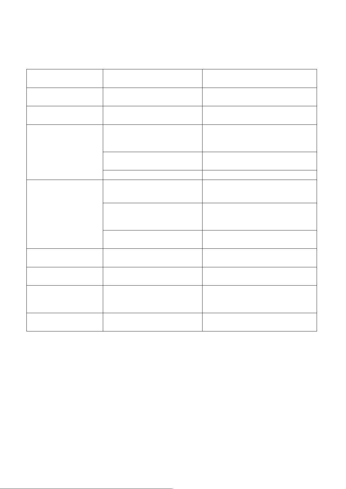
SERVICE HISTORY
This heat er must be serviced annually depending on usage.
Date Dealer
Name
Service technician
Name
Service Performed Special Concerns
NOTES:
23