Home
Bookmarks
Home
Carrier
Carrier 38MHRBQ12AA3 User Manual
Page 37
Carrier 38MHRBQ12AA3 Air Conditioner Cooling Area
User Manual - Page 37
For 38MHRBQ12AA3.
PDF File Manual
,
74 pages
,
Read Online
|
Download pdf file
SAFETY CONSIDERATIONS
INTRODUCTION
MODEL/SERIAL NUMBER NOMENCLATURES
SPECIFICATIONS
Compatibility
Performance
Compatibility
Performance
DIMENSIONS
CLEARANCES
ELECTRICAL DATA
WIRING
CONNECTION DIAGRAMS
WIRING DIAGRAMS (COOLING ONLY)
WIRING DIAGRAMS (HEAT PUMP)
REFRIGERATION CYCLE DIAGRAMS
REFRIGERANT LINES
General Refrigerant Line Sizing
SYSTEM EVACUATION and CHARGING
System Vacuum and Charge
Operation Modes and Functions
Point Check Function
TROUBLESHOOTING
Safety
OUTDOOR UNIT DIAGNOSTIC GUIDES
PCB DIAGRAMS
DIAGNOSIS and SOLUTION
EEPROM Parameter Error Diagnosis and Solution (E0/F4)
Indoor / outdoor unit's communication diagnosis and solution (E1)
Zero crossing detection error diagnosis and solution (E2)
Fan speed has been out of control diagnosis and solution (E3/F5)
Index 1
Open circuit or short circuit of temperature sensor diagnosis and solution (E4/E5/F1/F2/F3)
Refrigerant Leakage Detection diagnosis and solution (EC)
Overload current protection diagnosis and solution (F0)
IPM malfunction or IGBT over-strong current protection diagnosis and solution (P0)
Over voltage or too low voltage protection diagnosis and solution (P1)
High temperature protection of compressor top diagnosis and solution (P2)
Inverter compressor drive error diagnosis and solution (P4)
Main Parts Check
Compressor Checking
IPM Continuity Check
Fan Motor
Pressure on Service Port
DISASSEMBLY INSTRUCTIONS Sizes 12K (115V)
DISASSEMBLY INSTRUCTIONS Sizes 12K (208-230V)
DISASSEMBLY INSTRUCTIONS Sizes 18K (208-230V)
DISASSEMBLY INSTRUCTIONS Sizes 24K (208-230V)
APPENDIX
Appendix 1
Appendix 2
Appendix 3
Page 37/74
Page 1
Page 2
Page 3
Page 4
Page 5
Page 6
Page 7
Page 8
Page 9
Page 10
Page 11
Page 12
Page 13
Page 14
Page 15
Page 16
Page 17
Page 18
Page 19
Page 20
Page 21
Page 22
Page 23
Page 24
Page 25
Page 26
Page 27
Page 28
Page 29
Page 30
Page 31
Page 32
Page 33
Page 34
Page 35
Page 36
Page 37
Page 38
Page 39
Page 40
Page 41
Page 42
Page 43
Page 44
Page 45
Page 46
Page 47
Page 48
Page 49
Page 50
Page 51
Page 52
Page 53
Page 54
Page 55
Page 56
Page 57
Page 58
Page 59
Page 60
Page 61
Page 62
Page 63
Page 64
Page 65
Page 66
Page 67
Page 68
Page 69
Page 70
Page 71
Page 72
Page 73
Page 74
Contents
Table of Contents
Search
Previous
Next
Troubleshooting
Bookmarks
Loading ...
Loading ...
Loading ...
37
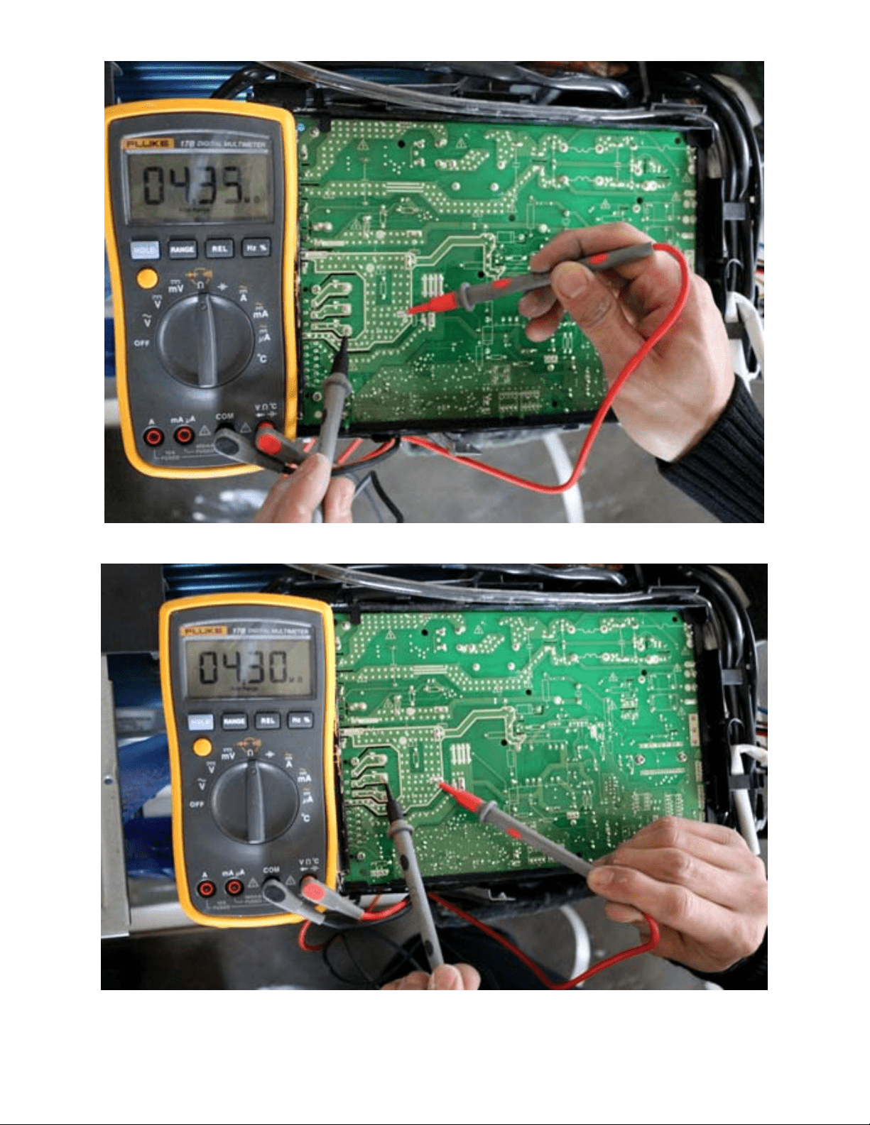
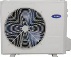
DIAGNOSIS
AND SOLUTION (CONT)
Fig. 36 – P−U
Fig. 37 – P−V
Loading ...
Loading ...
Loading ...
File type: PDF
File name: 69626017_38mhrbq12aa3.pdf
File size: 7.81 MB
File Language: English
Pages: 74
Author: Carrier
File created: 2018-08-15
Published: 2022-04-02
Updated: 2023-04-26
Download File
Table of Contents
×
SAFETY CONSIDERATIONS
1
INTRODUCTION
1
MODEL/SERIAL NUMBER NOMENCLATURES
2
SPECIFICATIONS
3
Compatibility
3
Performance
3
Compatibility
4
Performance
4
DIMENSIONS
5
CLEARANCES
8
ELECTRICAL DATA
9
WIRING
9
CONNECTION DIAGRAMS
10
WIRING DIAGRAMS (COOLING ONLY)
11
WIRING DIAGRAMS (HEAT PUMP)
14
REFRIGERATION CYCLE DIAGRAMS
17
REFRIGERANT LINES
18
General Refrigerant Line Sizing
18
SYSTEM EVACUATION and CHARGING
19
System Vacuum and Charge
19
Operation Modes and Functions
20
Point Check Function
22
TROUBLESHOOTING
23
Safety
23
OUTDOOR UNIT DIAGNOSTIC GUIDES
24
PCB DIAGRAMS
25
DIAGNOSIS and SOLUTION
27
EEPROM Parameter Error Diagnosis and Solution (E0/F4)
27
Indoor / outdoor unit's communication diagnosis and solution (E1)
28
Zero crossing detection error diagnosis and solution (E2)
30
Fan speed has been out of control diagnosis and solution (E3/F5)
31
Index 1
32
Open circuit or short circuit of temperature sensor diagnosis and solution (E4/E5/F1/F2/F3)
33
Refrigerant Leakage Detection diagnosis and solution (EC)
34
Overload current protection diagnosis and solution (F0)
35
IPM malfunction or IGBT over-strong current protection diagnosis and solution (P0)
36
Over voltage or too low voltage protection diagnosis and solution (P1)
40
High temperature protection of compressor top diagnosis and solution (P2)
41
Inverter compressor drive error diagnosis and solution (P4)
42
Main Parts Check
43
Compressor Checking
44
IPM Continuity Check
45
Fan Motor
45
Pressure on Service Port
46
DISASSEMBLY INSTRUCTIONS Sizes 12K (115V)
48
DISASSEMBLY INSTRUCTIONS Sizes 12K (208-230V)
54
DISASSEMBLY INSTRUCTIONS Sizes 18K (208-230V)
59
DISASSEMBLY INSTRUCTIONS Sizes 24K (208-230V)
65
APPENDIX
71
Appendix 1
71
Appendix 2
72
Appendix 3
73
Search:
×
Search