Loading ...
Loading ...
Loading ...
10
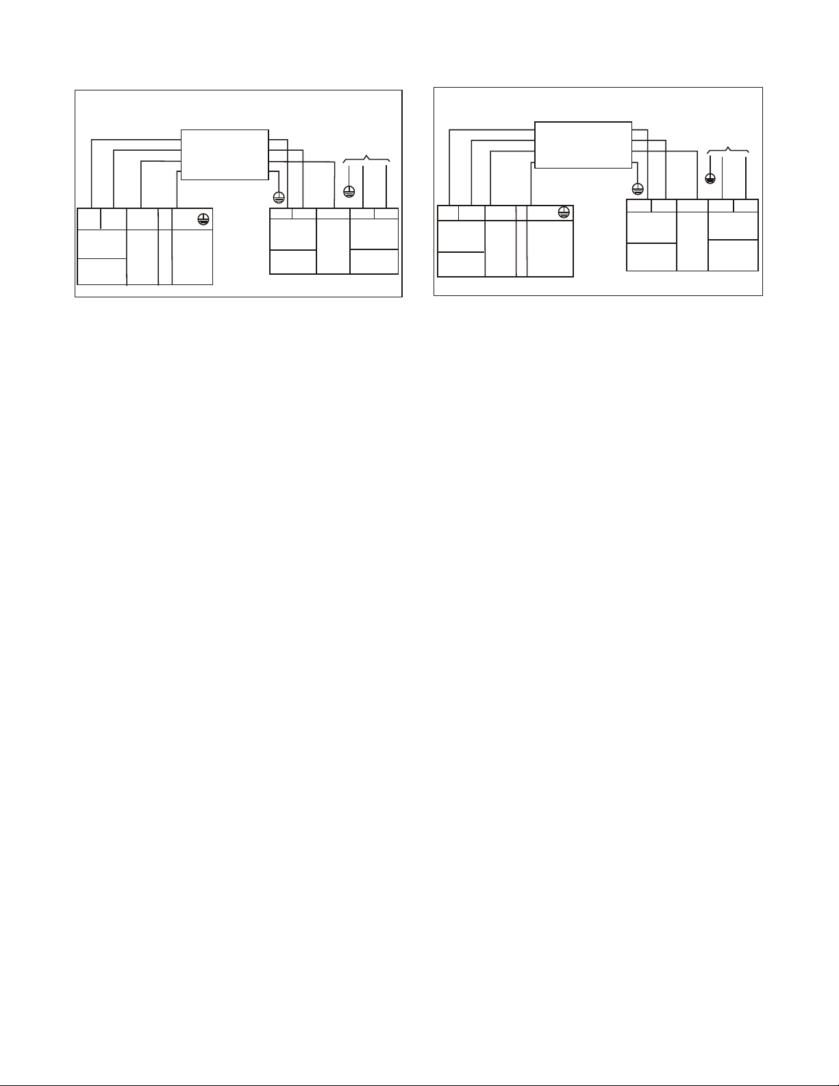
CONNECTION DIAGRAMS
S
L
N
115-1-60
Main
Power Supply
115-1-60
L
N
S
L
N
Power to
Indoor Unit
CONNECTING CABLE
OUTDOOR TO INDOOR
GND
Ground
Indoor
Signal
High
Voltage
115-1-60
115-1-60
FIELD POWER SUPPLY
GND
Indoor
Signal
High
Voltage
Indoor Unit
Power Supply
S
L1 L2
208/230-1-60
Main
Power Supply
L1
L2
S
L1
L2
CONNECTING CABLE
OUTDOOR TO INDOOR
Indoor Unit
Power Supply
208/230-1-60
Indoor
Signal
High
Voltage
GND
Ground
Power to
Indoor Unit
Indoor
Signal
High
Voltage
208/230-1-60
FIELD POWER SUPPLY
GND
208/230-1-60
115V Indoor Unit 115V Outdoor Unit 230V Indoor Unit 230V Outdoor Unit
Fig. 6 – Connection Diagrams
Notes:
1. Do not use thermostat wire for any connection between indoor and outdoor units.
2. All connections between indoor and outdoor units must be as shown. The connections are sensitive to polarity and will result in a fault code.
Loading ...
Loading ...
Loading ...