Service Manual
38MHRB
Outdoor Unit Single Zone Ductless System
Sizes 09 to 24
TABLE OF CONTENTS
PAGE
SAFETY CONSIDERATIONS 1.........................
INTRODUCTION 1...................................
MODEL/SERIAL NUMBER NOMENCLATURES 2.........
SPECIFICATIONS 3...................................
DIMENSIONS 5.....................................
CLEARANCES 8.....................................
ELECTRICAL DATA 9................................
WIRING 9...........................................
CONNECTION DIAGRAMS 10.........................
WIRING DIAGRAMS 11...............................
REFRIGERATION CYCLE DIAGRAMS 17................
REFRIGERANT LINES 18.............................
SYSTEM EVACUATION AND CHARGING 19.............
ELECTRONIC FUNCTIONS 18.........................
TROUBLESHOOTING 23..............................
OUTDOOR UNIT DIAGNOSTIC GUIDES 24..............
PCB DIAGRAMS 25..................................
DIAGNOSIS AND SOLUTION 27.......................
DISASSEMBLY INSTRUCTIONS 48.....................
APPENDIX 71.......................................
SAFETY CONSIDERATIONS
Installing, starting up, and servicing air−conditioning equipment
can be hazardous due to system pressures, electrical components,
and equipment location (roofs, elevated structures, etc.).
Only trained, qualified installers and service mechanics should
install, start−up, and service this equipment.
Untrained personnel can perform basic maintenance functions such
as cleaning coils. All other operations should be performed by
trained service personnel.
When working on the equipment, observe precautions in the
literature and on tags, stickers, and labels attached to the
equipment.
Follow all safety codes. Wear safety glasses and work gloves. Keep
quenching cloth and fire extinguisher nearby when brazing. Use
care in handling, rigging, and setting bulky equipment.
Read this manual thoroughly and follow all warnings or cautions
included in literature and attached to the unit. Consult local building
codes and National Electrical Code (NEC) for special requirements.
Recognize safety information. This is the safety−alert symbol
!
!
.
When you see this symbol on the unit and in instructions or manuals,
be alert to the potential for personal injury. Understand these signal
words: DANGER, WARNING, and CAUTION.
These words are used with the safety−alert symbol. DANGER
identifies the most serious hazards which will result in severe
personal injury or death. WARNING signifies hazards which
could result in personal injury or death. CAUTION is used to
identify unsafe practices which may result in minor personal injury
or product and property damage. NOTE is used to highlight
suggestions which will result in enhanced installation, reliability, or
operation.
!
WARNING
ELECTRICAL SHOCK HAZARD
Failure to follow this warning could result in personal
injury or death.
Before installing, modifying, or servicing system, main
electrical disconnect switch must be in the OFF
position. There may be more than 1 disconnect switch.
Lock out and tag switch with a suitable warning label.
EXPLOSION HAZARD
Failure to follow this warning could
result in death, serious personal injury,
and/or property damage.
Never use air or gases containing
oxygen for leak testing or operating
refrigerant compressors. Pressurized
mixtures of air or gases containing
oxygen can lead to an explosion.
!
WARNING
CAUTION
!
EQUIPMENT DAMAGE HAZARD
Failure to follow this caution may result in equipment
damage or improper operation.
Do not bury more than 36 in. (914 mm) of refrigerant pipe
in the ground. If any section of pipe is buried, there must be
a 6 in. (152 mm) vertical rise to the valve connections on
the outdoor units. If more than the recommended length is
buried, refrigerant may migrate to the cooler buried section
during extended periods of system shutdown. This causes
refrigerant slugging and could possibly damage the
compressor at start−up.
INTRODUCTION
This Service Manual provides the necessary information to service,
repair, and maintain the outdoor units. Section 2 of this manual has
an appendix with data required to perform troubleshooting. Use the
Table of Contents to locate a desired topic.
2
MODEL/SERIAL NUMBER NOMENCLATURES
Table 1—Unit Sizes
Cooling Only
SYSTEM TONS BTUh VOLTAGE - PHASE OUTDOOR MODEL
1.00 12,000 115-1 38MHRBC12AA1
1.00 12,000 208/230-1 38MHRBC12AA3
1.50 18,000 208/230-1 38MHRBC18AA3
2.00 24,000 208/230-1 38MHRBC24AA3
Heat Pump
1.00 12,000 115-1 38MHRBQ12AA1
0.75 9,000 208/230-1 38MHRBQ09AA3
1.00 12,000 208/230-1 38MHRBQ12AA3
1.50 18,000 208/230-1 38MHRBQ18AA3
2.00 24,000 208/230-1 38MHRBQ24AA3
BR09
MAJOR SERIES
UNIT TYPE
R = OUTDOOR UNIT
MAXIMUM NUMBER OF FAN COIL UNITS THAT
CAN BE CONNECTED TO THE OUTDOOR UNIT
A = 1:1
OUTDOOR UNIT
38 MH 3Q
38 = OUTDOOR UNIT
MH = MODEL
VOLTAGE
1 =115-1-60
3 = 208/230-1-60
SYSTEM TYPE
C = COOLING ONLY
Q = HEAT PUMP
NOMINAL CAPACITY
09 - 3/4 TON
12 - 1 TON
18 - 1-1/2 TONS
24 - 2 TONS
A
A
VARIATIONS
A = STANDARD
01 18
Week of Manufacture
Year of Manufacture
10001
Sequential Serial Number
V
V = ALL MODELS
Use of the AHRI Certified
TM Mark indicates a
manufacturer’s
participation in the
program For verification
of certification for individual
products, go to
www.ahridirectory.org.

3
SPECIFICATIONS
Table 2—Specifications (Cooling Only)
System
Size 12 12 18 24
Outdoor Model 38MHRBC12AA1 38MHRBC12AA3 38MHRBC18AA3 38MHRBC24AA3
Electrical
Voltage, Phase, Cycle V/Ph/Hz 115-1-60 208/230-1-60 208/230-1-60 208/230-1-60
MCA A. 13 11 15 18
MOCP - Fuse Rating A. 20 15 20 25
Operating
Range
Cooling Outdoor DB
Min - Max
°F (°C) 0~122 (-17~50) 0~122 (-17~50) 0~122 (-17~50) 0~122 (-17~50)
Piping
Total Piping Length ft (m) 82 (25) 82 (25) 98 (30) 164 (50)
Piping Lift
*
ft (m) 33 (10) 33 (10) 66 (20) 66 (20)
Pipe Connection
Size - Liquid
in (mm) 1/4 (6.35) 1/4 (6.35) 1/4 (6.35) 3/8 (9.52)
Pipe Connection
Size - Suction
in (mm) 1/2 (12.7) 1/2 (12.7) 1/2 (12.7) 5/8 (16)
Refrigerant
Type R410A R410A R410A R410A
Charge lbs (kg) 1.30 (0.59) 1.17 (0.53) 1.98 (0.90) 2.56 (1.16)
Metering Device EEV EEV EEV EEV
Outdoor Coil
Face Area Sq. Ft. 4.15 4.15 4.15 4.78
No. Rows 1 1 2 2
Fins per inch 22 22 22 22
Circuits 2 2 4 6
Compressor
Type Rotary Inverter Rotary Inverter Rotary Inverter Rotary Inverter
Model ASN98D22UFZ ASK89D29UEZD ASN140D21UFZ ATN150D30UFZA
Oil Type VG74 VG74 VG74 VG74
Oil Charge Fl. Oz. 13.0 13.0 15.5 23.6
Rated Current RLA 9.5 6.8 9.0 12.0
Outdoor
Unit Width in (mm) 30.31 (770) 30.31 (770) 30.31 (770) 33.27 (845)
Unit Height in (mm) 21.85 (555) 21.85 (555) 21.85 (555) 27.64 (702)
Unit Depth in (mm) 11.81 (300) 11.81 (300) 11.81 (300) 14.29 (363)
Net Weight lbs (kg) 57.8 (26.2) 53.8 (24.4) 65.9 (29.9) 88.6 (40.2)
Airflow CFM 1,170 1,230 1,195 1,825
Sound Pressure dB(A) 52.0 53.6 55.3 58.0
Compatibility
Table 3—Compatibility
Indoor Unit
38MHRBC12AA1 38MHRBC12AA3 38MHRBC18AA3 38MHRBC24AA3
High Wall
40MHHC12---1 ●
40MHHC12---3 ●
40MHHC18---3 ●
40MHHC24---3 ●
Performance
Table 4—Performance
High Wall
Indoor Model 40MHHC12---1 40MHHC12---3 40MHHC18---3 40MHHC24---3
Energy Star NO NO NO NO
Cooling System Tons 1.0 1.0 1.4 1.8
Cooling Rated Capacity Btu/h 12,000 11,500 17,000 22,000
Cooling Cap. Range Min - Max Btu/h 4,800~13,200 4,800~13,000 5,800~18,600 4,900~24,100
SEER 17.3 19.0 19.0 18.5
EER 10.7 11.2 10.3 11.1

4
SPECIFICATIONS (CONT)
Table 5—Specifications (Heat Pump)
System
Size 12 9 12 18 24
Outdoor Model 38MHRBQ12AA1 38MHRBQ09AA3 38MHRBQ12AA3 38MHRBQ18AA3 38MHRBQ24AA3
Electrical
Voltage, Phase, Cycle V/Ph/Hz 115-1-60 208/230-1-60 208/230-1-60 208/230-1-60 208/230-1-60
MCA A. 13 8 10 15 18
MOCP - Fuse Rating A. 20 15 15 20 25
Operating
Range
Cooling Outdoor DB Min - Max °F (°C)
0~ 122
(-17~ 50)
0~ 122
(-17~ 50)
0~ 122
(-17~ 50)
0~ 122
(-17~ 50)
0~ 122
(-17~ 50)
Heating Outdoor DB Min - Max °F (°C)
0~ 86
(-17~ 30)
0~ 86
(-17~ 30)
0~ 86
(-17~ 30)
0~ 86
(-17~ 30)
0~ 86
(-17~ 30)
Piping
Total Piping Length ft (m) 82 (25) 82 (25) 82 (25) 98 (30) 164 (50)
Piping Lift
*
ft (m) 33 (10) 33 (10) 33 (10) 66 (20) 66 (20)
Pipe Connection Size - Liquid in (mm) 1/4 (6.35) 1/4 (6.35) 1/4 (6.35) 1/4 (6.35) 3/8 (9.52)
Pipe Connection Size - Suction in (mm) 1/2 (12.7) 3/8 (9.52) 1/2 (12.7) 1/2 (12.7) 5/8 (16)
Refrigerant
Type R410A R410A R410A R410A R410A
Charge lbs (kg) 2.12 (0.96) 1.76 (0.80) 2.12 (0.96) 2.82 (1.28) 3.97 (1.80)
Metering Device EEV EEV EEV EEV EEV
Outdoor Coil
Face Area Sq. Ft. 4.1 4.1 4.1 4.7 5.3
No. Rows 1.6 1 1.6 2 2
Fins per inch 18 18 18 21 18
Circuits 2 2 4 4 6
Compressor
Type Rotary Inverter Rotary Inverter Rotary Inverter Rotary Inverter Rotary Inverter
Model ASN98D22UFZ ASN98D22UFZ ASN98D22UFZ ASN140D21UFZ ATF235D22UMT
Oil Type VG74 VG74 VG74 VG74 VG74
Oil Charge Fl. Oz. 13.0 13.0 13.0 15.5 23.6
Rated Current RLA 10.5 5.5 6.8 10.5 12.0
Outdoor
Unit Width in (mm) 30.31 (770) 30.31 (770) 30.31 (770) 31.50 (800) 33.27 (845)
Unit Height in (mm) 21.85 (555) 21.85 (555) 21.85 (555) 21.81 (554) 27.64 (702)
Unit Depth in (mm) 11.81 (300) 11.81 (300) 11.81 (300) 13.11 (333) 14.29 (363)
Net Weight lbs (kg) 69 (31.3) 63 (28.6) 65.5 (29.7) 79.6 (36.1) 114.2 (51.8)
Airflow CFM 1,170 1,170 1,170 1,170 1,765
Sound Pressure dB(A) 54.5 57.2 57.4 57.0 60.2
Compatibility
Table 6—Compatibility
Indoor Unit 38MHRBQ12AA1 38MHRBQ09AA3 38MHRBQ12AA3 38MHRBQ18AA3 38MHRBQ24AA3
High Wall
40MHHQ12---1 ●
40MHHQ09---3 ●
40MHHQ12---3 ●
40MHHQ18---3 ●
40MHHQ24---3 ●
Performance
Table 7—Performance
High Wall
Indoor Model 40MHHQ12---1 40MHHQ09---3 40MHHQ12---3 40MHHQ18---3 40MHHQ24---3
Energy Star NO NO NO NO NO
Cooling System Tons 1.0 0.8 1.0 1.5 2.0
Cooling Rated Capacity Btu/h 12,000 9,000 12,000 18,000 24,000
Cooling Cap. Range Min - Max Btu/h 3,700~ 13,000 3,400~ 10,500 3,700~ 13,000 5,500~ 19,000 8,987~ 26,585
SEER 19.8 18.5 19.8 19.0 17.3
EER 10 11.2 11.2 11.2 9.7
Heating Rated Capacity (47° F) Btu/h 12,000 9,800 12,000 18,000 24,800
Heating Rated Capacity (17° F) Btu/h 8,000 7,500 9,230 11,600 18,000
Heating Maximum Capacity (17° F) Btu/h 8,200 7,850 9,500 11,800 18,300
Heating Maximum Capacity (5° F) Btu/h 9,000 6,070 8,880 10,150 16,760
Heating Cap. Range Min - Max Btu/h 3,500~ 13,500 2,800~ 11,500 3,500~ 13,500 6,200~ 19,000 8,371~ 25,350
HSPF 10.6 10.0 9.6 10.6 9.6
COP (47° F) W/W 2.93 3.27 3.22 3.26 3.13
COP (17° F) W/W 2.58 2.58 2.64 2.64 2.49
COP (5° F) W/W 1.60 1.60 1.60 1.50 1.40
5
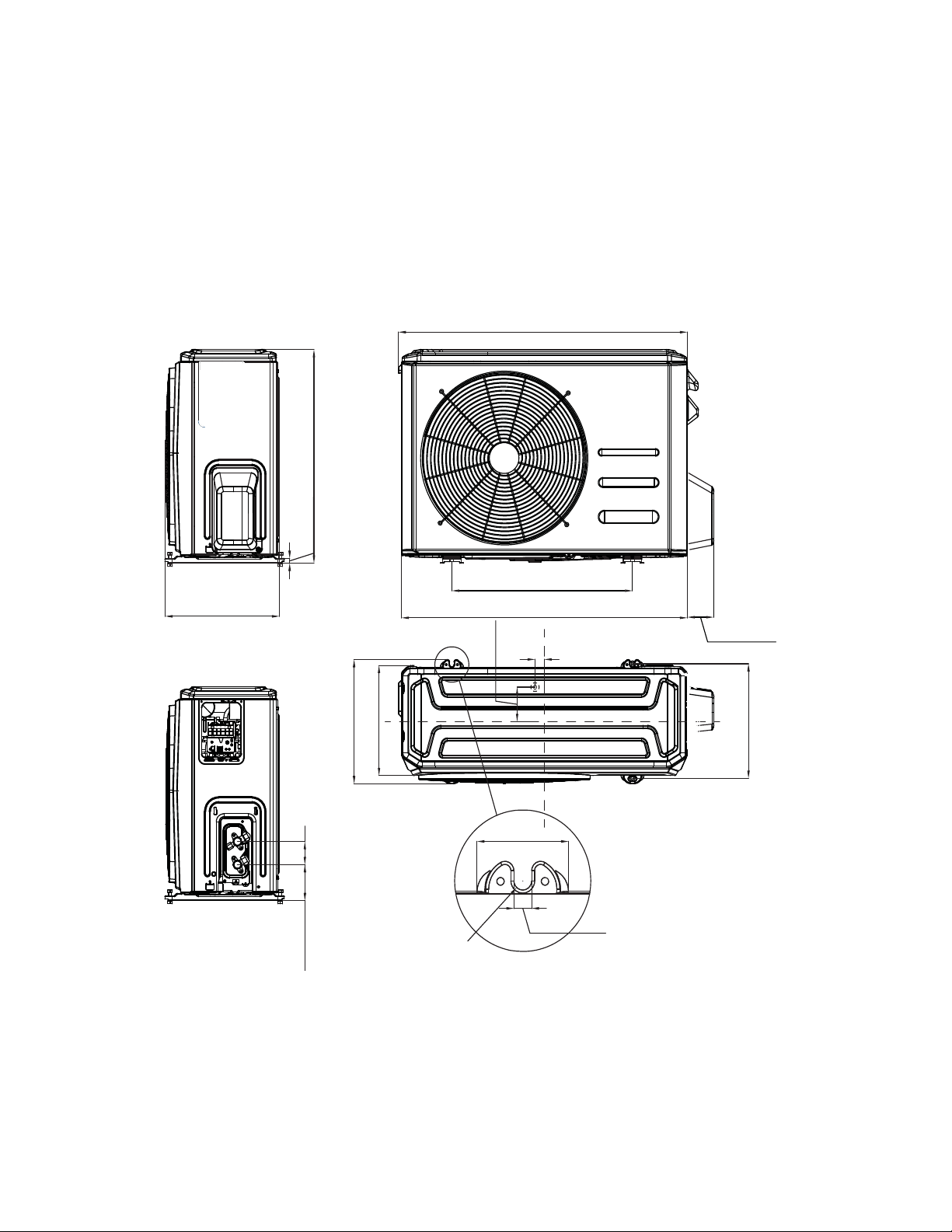
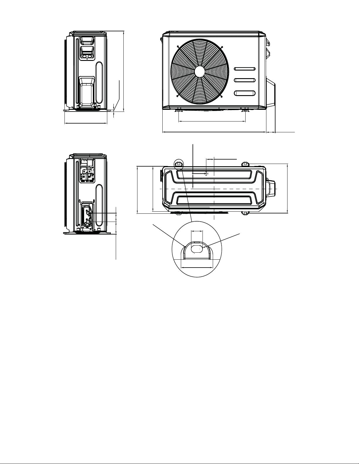
DIMENSIONS
Table 8—Dimensions
Cooling
Only
System Size Height (H) in. (mm) Width (W) in. (mm) Depth (D) in. (mm) Weight-Net lbs. (kg)
12K (115V) 21.85(555) 30.31(770) 11.81(300) 57.8(26.2)
12K (208/230V) 21.85(555) 30.31(770) 11.81(300) 53.8(24.4)
18K (208/230V) 21.85 (555) 30.31 (770) 11.81 (300) 65.9 (29.9)
24K (208/230V) 27.64(702) 33.27(845) 14.29(363) 88.6(40.2)
Heat
Pump
System Size Height (H) in. (mm) Width (W) in. (mm) Depth (D) in. (mm) Weight-Net lbs. (kg)
12K (115V) 21.85(555) 30.31(770) 11.81(300) 69(31.3)
9K (208/230V) 21.85(555) 30.31(770) 11.81(300) 63(28.6)
12K (208/230V) 21.85(555) 30.31(770) 11.81(300) 65.5(29.7)
18K (208/230V) 21.81(554) 31.50(800) 13.11(333) 79.6(36.1)
24K (208/230V) 27.64(702) 33.27(845) 14.29(363) 114.2(51.8)
19.17(487) W1
2.76(70) W
11.73(298)
21.85(555)
11.81(300) D
H
0.47(12)
2.36(60)
3.66(93)
H1
H2
D1
30.31(770) W
30.66(779) W3
13.07(322)
D2
0.98(25) B1
3.54(90) B2
2.42(61.5) A2
0.47(12) A1
R
0
.24(6)
11.26(286)
D3
Unit: inch(mm)
Fig. 1 – Sizes 9K and 12K Heat Pump and Size 18K Cooling Only
6
DIMENSIONS − OUTDOOR (CONT)
31.50 (800)
20.24 (514)
21.81 (554)
2.36 (6 0)
3.37 (8 5.5)
13.39 (340)
0.47 (1 2)
12.24 (311)
12.80 (325)
13.11
(333)
2.76 (7 0)
H
H1
H2
D1
D2
D3
2.43 (6 1.8)
4.17 (1 06)
0.87 (2 2)
R
0
.
7
9
(R
2
0
)
R
0
.
2
4
(
R
6
)
2.43 (6 1.6)
D
W
W1
W2
B1
B2
A2
A1
Unit: inch(mm)
Fig. 2 – Size 18K Heat Pump
7
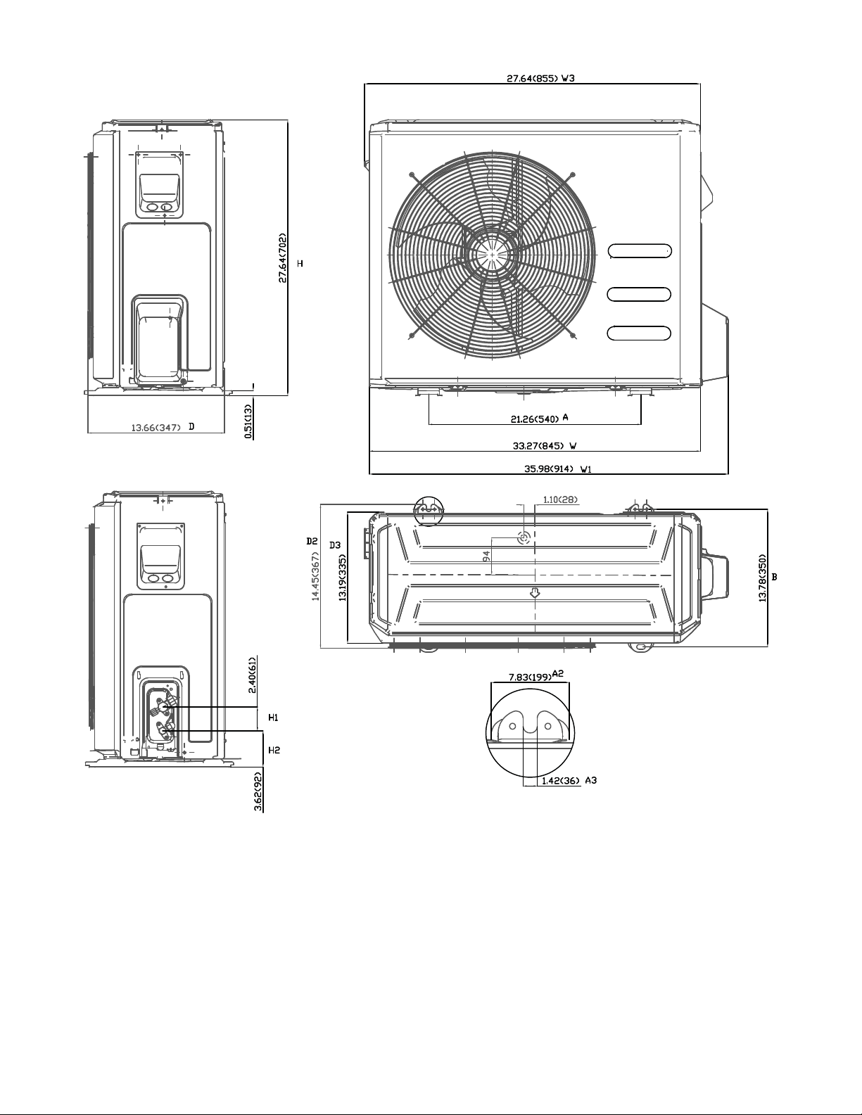
DIMENSIONS − OUTDOOR (CONT)
Unit: inch (mm)
Fig. 3 – Size 24K
8
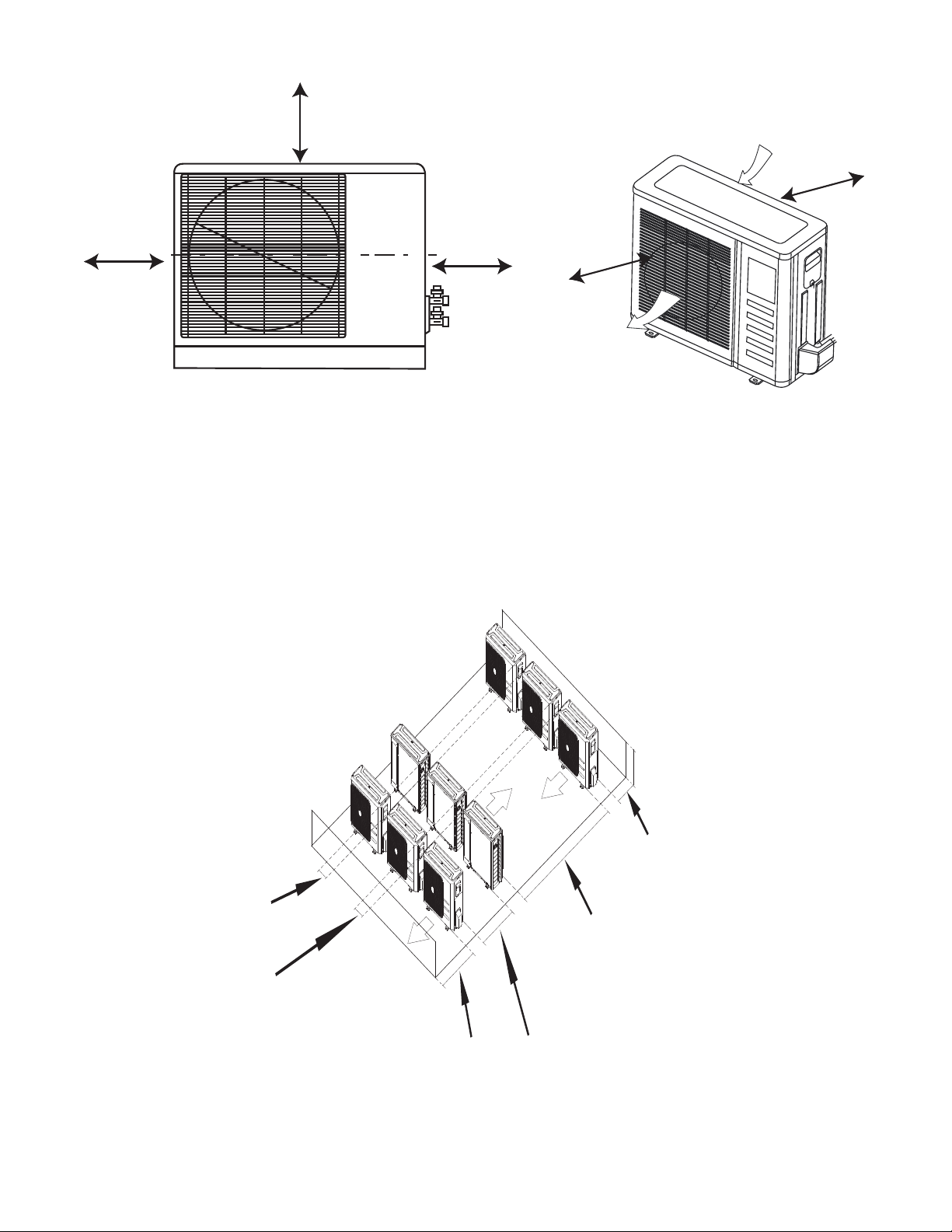
CLEARANCES
A
D
B
Air-outlet
Air-inlet
C
E
Fig. 4 – Outdoor Unit Clearance
Table 9—Clearances
UNIT
MINIMUM VALUE in. (mm)
A 24 (610)
B 24 (610)
C 24 (610)
D 4 (101)
E 4 (101)
NOTE: The outdoor unit must be mounted at least 2in. (50mm) above the maximum anticipated snow depth.
118in (300cm) or more
19in (48cm) or more
on a multiple parallel
unit arrangement
4in (10cm) or more on
a single parallel unit
arrangement
24in (60cm)
or more
59in (150cm)
or more on a
multiple parallel
unit arrangement
24in (61cm) or more
on a single parallel
unit arrangement
9.8in (25cm)
or more for
proper airow
24in (61cm) or
more is
recommended
for service
9.8in (25cm)
or more for
proper airow
24in (61cm)
or more is
recommended
for service
Fig. 5 – Clearances for Multiple Units
9
ELECTRICAL DATA
Table 10—Electrical Data (Cooling Only)
Cooling Only
Outdoor Unit Size 12K 12K 18K 24K
Volts-PH-Hz (115V) (208/230V) (208/230V) (208/230V)
Max – Min*
Oper. Voltage
127-104 253-187 253-187 253-187
Power Supply
MCA 13 11 15 18
MOCP 20 15 20 25
Compressor RLA 9.5 6.8 9 12
Outdoor Fan Motor
FLA 0.6 0.5 0.6 0.6
Rated HP 0.054 0.054 0.054 0.068
Output 40 40 40 50
Table 11—Electrical Data (Heat Pump)
Heat Pump
Outdoor Unit Size 12K 9K 12K 18K 24K
Volts-PH-Hz (115V) (208/230V) (208/230V) (208/230V) (208/230V)
Max – Min*
Oper. Voltage
127-104 253-187 253-187 253-187 253-187
Power Supply
MCA 13 8 10 15 18
MOCP 20 15 15 20 25
Compressor RLA 10.5 5.5 6.8 10.5 12
Outdoor Fan Motor
FLA 0.6 0.4 0.4 0.5 0.6
Rated HP 0.054 0.054 0.054 0.054 0.068
Output 40 40 40 40 50
*Permissible limits of the voltage range at which the unit will operate satisfactorily.
LEGEND
FLA - Full Load Amps
MCA - Minimum Circuit Amps
MOCP - Maximum Over-Current Protection
RLA - Rated Load Amps
WIRING
All wires must be sized per NEC (National Electrical Code) or
CEC (Canadian Electrical Code) and local codes. Use Electrical
Data table MCA (minimum circuit amps) and MOCP (maximum
over current protection) to correctly size the wires and the
disconnect fuse or breakers respectively.
Recommended Connection Method for Power and
Communication Wiring:
The main power is supplied to the outdoor unit. The field supplied
14/3 stranded wire with ground with a 600 volt insulation rating,
power/communication wiring from the outdoor unit to indoor unit
consists of four (4) wires and provides the power for the indoor
unit. Two wires are line voltage AC power, one is communication
wiring (S) and the other is a ground wire. Wiring between indoor
and outdoor unit is polarity sensitive. The use of BX wire is NOT
recommended.
If installed in a high Electromagnetic field (EMF) area and
communication issues exists, a 14/2 stranded shielded wire can be
used to replace L2/N and (S) between outdoor unit and indoor unit
landing the shield onto ground in the outdoor unit only.
CAUTION
!
EQUIPMENT DAMAGE HAZARD
Failure to follow this caution may result in equipment
damage or improper operation.
Wires should be sized based on NEC and local codes.
CAUTION
!
EQUIPMENT DAMAGE HAZARD
Failure to follow this caution may result in equipment damage
or improper operation.
SBe sure to comply with local codes while running wire from
the indoor unit to the outdoor unit.
SEvery wire must be connected firmly. Loose wiring may
cause the terminal to overheat or result in unit malfunction.
A fire hazard may also exist. Ensure all wiring is tightly
connected.
SNo wire should touch the refrigerant tubing, compressor or
any moving parts.
SDisconnecting means must be provided and shall be located
within sight and readily accessible from the air conditioner.
SConnecting cable with conduit shall be routed through the
hole in the conduit panel.
10
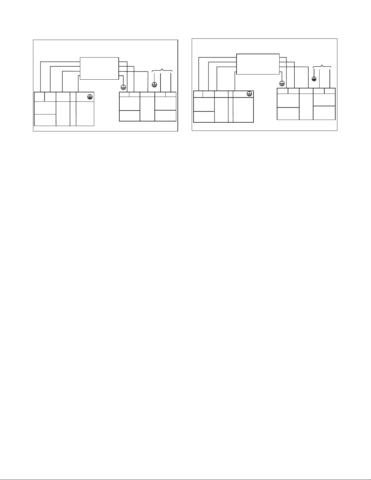
CONNECTION DIAGRAMS
S
L
N
115-1-60
Main
Power Supply
115-1-60
L
N
S
L
N
Power to
Indoor Unit
CONNECTING CABLE
OUTDOOR TO INDOOR
GND
Ground
Indoor
Signal
High
Voltage
115-1-60
115-1-60
FIELD POWER SUPPLY
GND
Indoor
Signal
High
Voltage
Indoor Unit
Power Supply
S
L1 L2
208/230-1-60
Main
Power Supply
L1
L2
S
L1
L2
CONNECTING CABLE
OUTDOOR TO INDOOR
Indoor Unit
Power Supply
208/230-1-60
Indoor
Signal
High
Voltage
GND
Ground
Power to
Indoor Unit
Indoor
Signal
High
Voltage
208/230-1-60
FIELD POWER SUPPLY
GND
208/230-1-60
115V Indoor Unit 115V Outdoor Unit 230V Indoor Unit 230V Outdoor Unit
Fig. 6 – Connection Diagrams
Notes:
1. Do not use thermostat wire for any connection between indoor and outdoor units.
2. All connections between indoor and outdoor units must be as shown. The connections are sensitive to polarity and will result in a fault code.
11
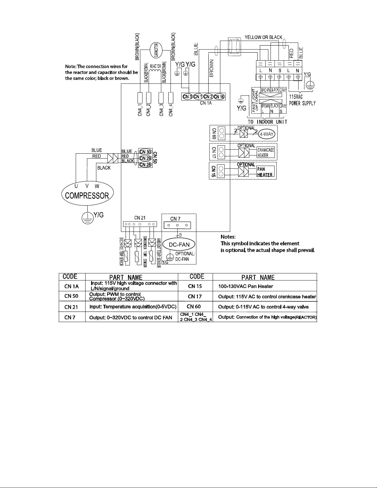
WIRING DIAGRAMS (COOLING ONLY)
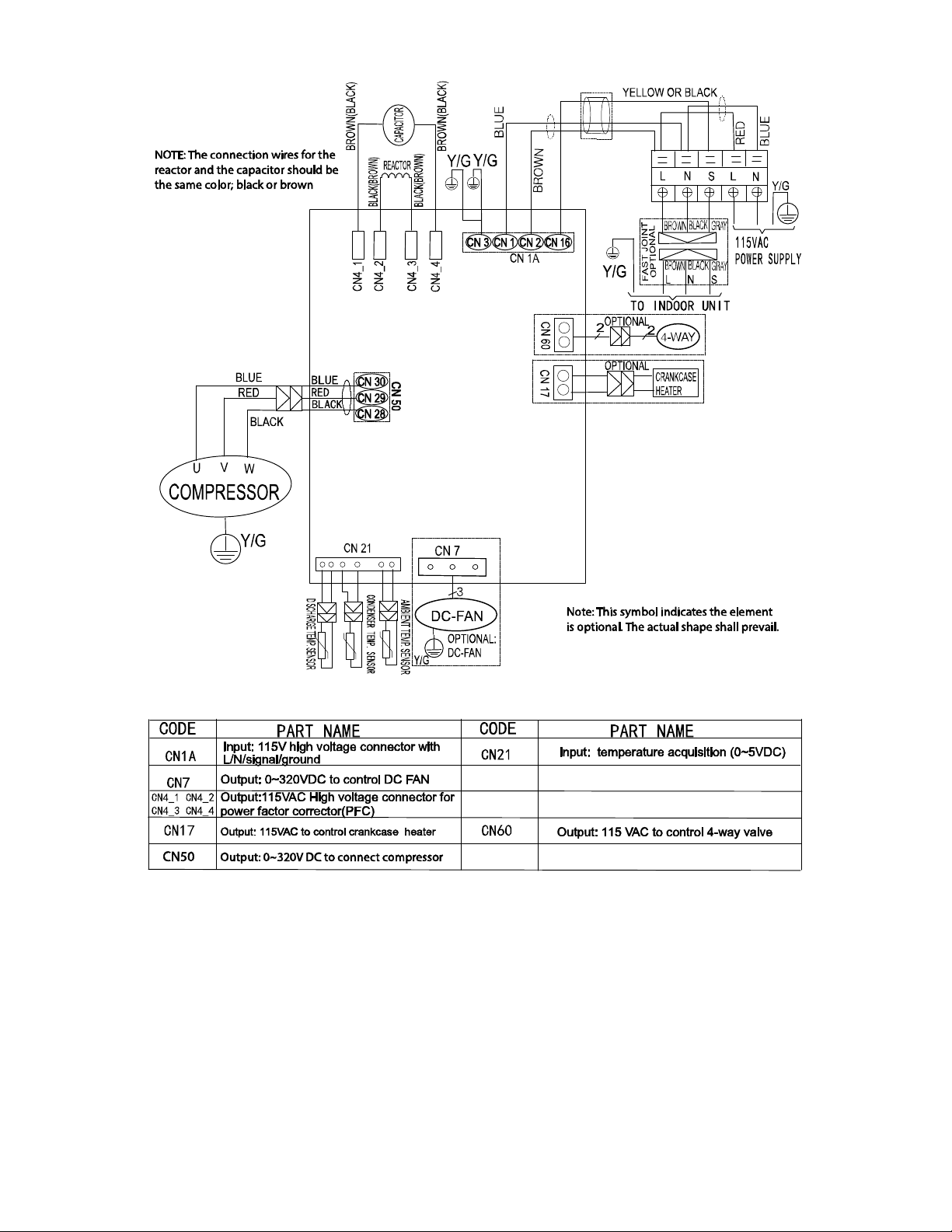
Fig. 7 – Wiring Diagram Size − Cooling Only Size 12K (115V)
12
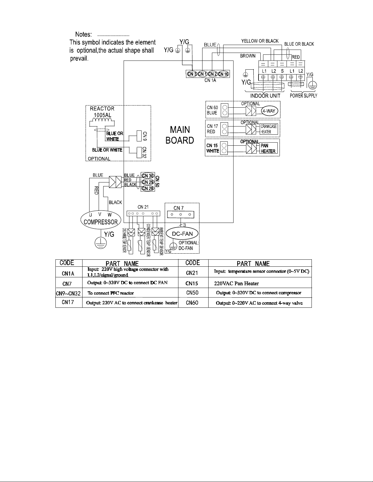
WIRING DIAGRAMS (COOLING ONLY (CONTINUED))
Fig. 8 – Wiring Diagram Cooling Only Size 12K (230V)
13
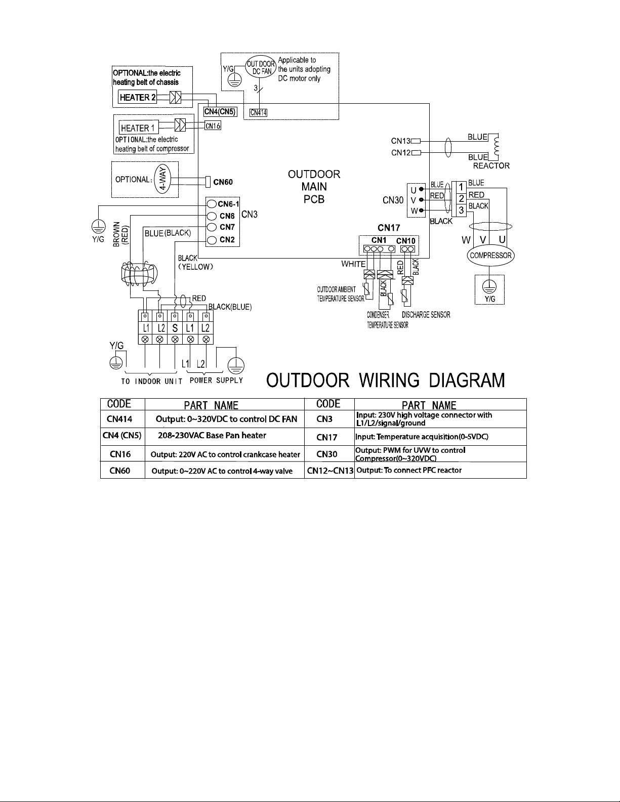
WIRING DIAGRAMS (COOLING ONLY (CONTINUED))
Fig. 9 – Wiring Diagram Cooling Only Sizes 18−24K
14
WIRING DIAGRAMS (HEAT PUMP)
Fig. 10 – Wiring Diagram Heat Pump Size 12K (115V)
15
WIRING DIAGRAMS (HEAT PUMP (CONTINUED))
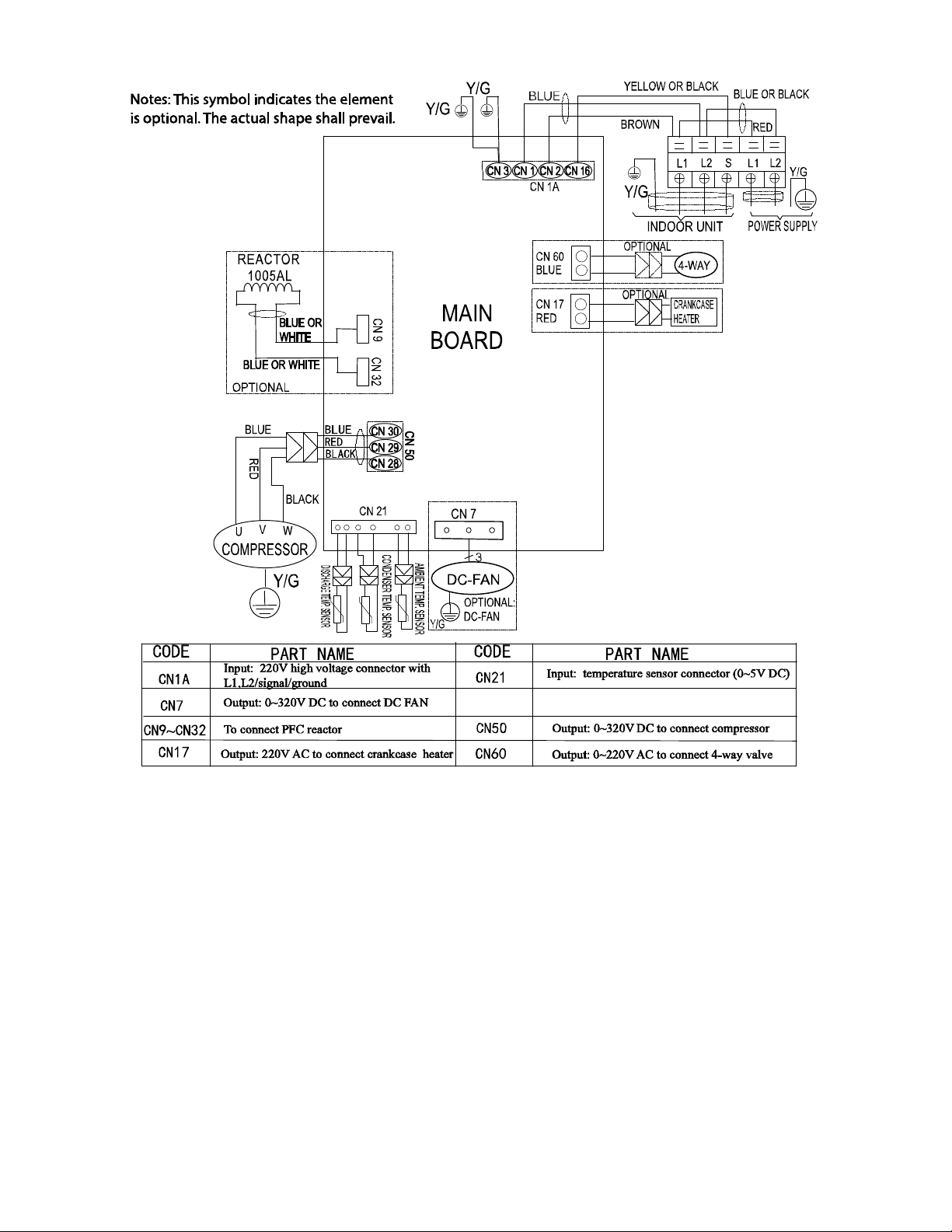
Fig. 11 – Wiring Diagram Heat Pump Sizes 09, 12, 18 (230V)
16
WIRING DIAGRAMS (HEAT PUMP (CONTINUED))
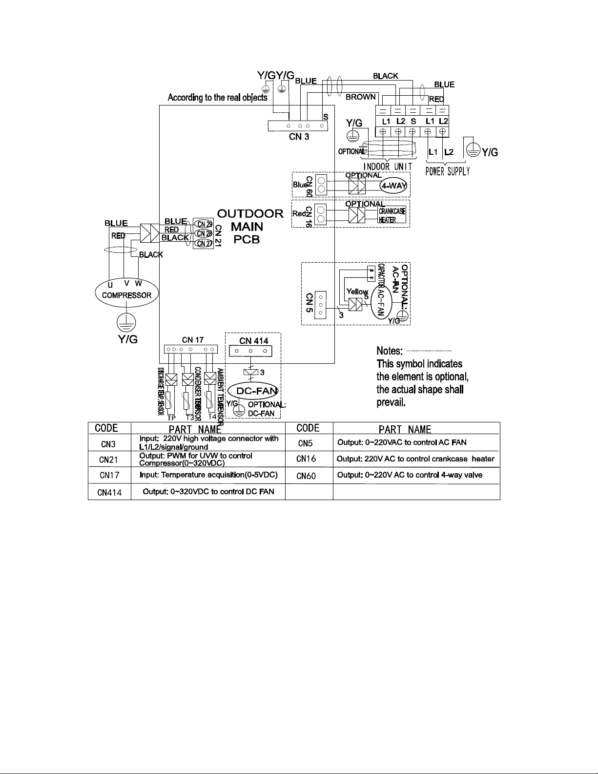
Fig. 12 – Wiring Diagram Heat Pump Size 24 (230V)
17
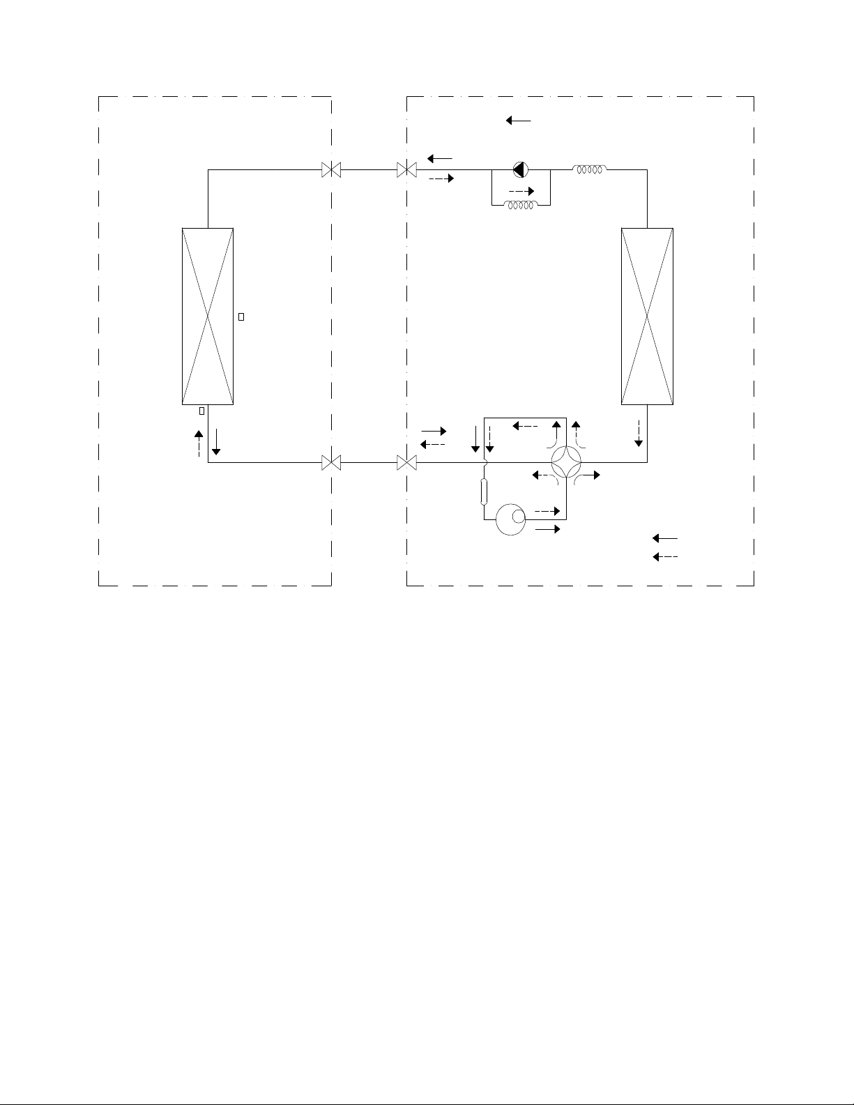
REFRIGERATION CYCLE DIAGRAMS
LIQUID SIDE
GAS SIDE
HEAT
EXCHANGE
(EVAPORATOR)
HEAT
EXCHANGE
(CONDENSER)
COMPRESSOR
2−WAY VALVE
3−WAY VALVE
4−WAY VALVE
COOLING
HEATING
T2 Evaporator
temp. sensor
T1 Room temp.
sensor
ACCUMULATOR
INDOOR OUTDOOR
CHECK VALVE
(Heating Model only)
CAPILIARY TUBE
Fig. 13 – Heat Pumps

18
REFRIGERANT LINES
General Refrigerant Line Sizing
1 The outdoor units are shipped with a full charge of R410A
refrigerant. All charges, line sizing, and capacities are based
on runs of 25ft. (7.6 m). For runs over 25 ft. (7.6 m),
consult the long−line applications section for the proper
charge adjustments.
2 The minimum refrigerant line length between the indoor
and outdoor units is 10 ft. (3 m).
3 Refrigerant lines should not be buried in the ground. If it is
necessary to bury the lines, not more than 36 in (914 mm)
should be buried. Provide a minimum 6in (152 mm)
vertical rise to the service valves to prevent refrigerant
migration.
4 Both lines must be insulated. Use a minimum of 1/2in.
(12.7 mm) thick insulation. Closed−cell insulation is
recommended in all long−line applications.
5 Special consideration should be given to isolating
interconnecting tubing from the building structure. Isolate
the the tubing so vibration or noise is not transmitted into
the structure.
IMPORTANT: Both refrigerant lines must be insulated
separately.
Table 12 lists the maximum lengths allowed.
Table 12—Piping and Refrigerant Information
System Size 12K (115V) 9K (208-230V) 12K (208-230V) 18K (208-230V) 24K (208-230V)
Piping
Min. Piping Length ft. (m) 10(3) 10(3) 10(3) 10(3) 10(3)
Standard Piping Length
ft. (m)
25(7.5) 25(7.5) 25(7.5) 25(7.5) 25(7.5)
Max. outdoor-indoor
height difference
(OU higher than IU)
ft. (m)
33(10) 33(10) 33(10) 66(20) 66(20)
Max. outdoor-indoor
height difference
(IU higher than OU)
ft. (m)
33(10) 33(10) 33(10) 66(20) 66(20)
Max. Piping Length with
no additional refrigerant
charge per System
(Standard Piping length)
ft. (m) 25(7.5) 25(7.5) 25(7.5) 25(7.5) 25(7.5)
Total Max. Piping
Length per system
ft. (m) 82(25) 82(25) 82(25) 98(30) 164(50)
Additional refrigerant
charge (between Standard
– Max piping length)
Oz/ft (g/m) 0.161(15) 0.161(15) 0.161(15) 0.161(15) 0.322(30)
Suction Pipe
(size - connection type)
In (mm) 1/2(12.7) 3/8(9.52) 1/2(12.7) 1/2(12.7) 5/8(15.9)
Liquid Pipe
(size - connection type)
In (mm) 1/4(6.35) 1/4(6.35) 1/4(6.35) 1/4(6.35) 3/8(9.52)
Refrigerant Type Type R410A R410A R410A R410A R410A
Refrigerant
Cooling Only Models
Charge Amount
Lbs (kg) 1.30(0.59) N/A 1.17 (0.53) 1.98 (0.9) 2.56 (1.16)
Heat Pump Models
Charge Amount
Lbs (kg) 2.12(0.96) 1.76(0.8) 2.12(0.96) 2.82 (1.28) 3.97 (1.8)
Long Line Applications,:
1 No change in line sizing is required.
2 Add refrigerant per Table 12.
19
SYSTEM EVACUATION AND
CHARGING
UNIT DAMAGE HAZARD
Failure to follow this caution may result in equipment
damage or improper operation.
Never use the system compressor as a vacuum pump.
CAUTION
!
Refrigerant tubes and indoor coil should be evacuated using the
recommended deep vacuum method of 500 microns. Always break
a vacuum with dry nitrogen.
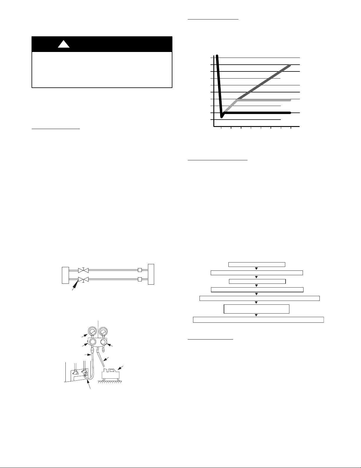
System Vacuum and Charge
Using Vacuum Pump
1 Completely tighten all flare nuts and connect manifold gage
charge hose to a charge port of the low side service valve
(see Fig. 14).
2 Connect the charge hose to the vacuum pump.
3 Fully open the low side of manifold gage (see Fig. 15).
4 Start the vacuum pump
5 Evacuate using the triple evacuation method.
6 After evacuation is complete, fully close the low side of
manifold gage and stop the vacuum pump operation.
7 The factory charge contained in the outdoor unit is good
for up to 25 ft. (8 m) of line length. For refrigerant lines
longer than 25 ft. (8 m), add refrigerant as specified in the
ADDITIONAL REFRIGERANT CHARGE table in this
document.
8 Disconnect the charge hose from the charge connection of
the low side service valve.
9 Fully open service valves B and A.
10 Securely tighten the service valves caps.
Outdoor Unit
Indoor Uni
t
Refrigerant
Service Valve
Low Side
High Side
A
B
C
D
Fig. 14 – Service Valve
Manifold Gage
500 microns
Low side valve
High side valve
Charge hose
Charge hose
Vacuum pump
Low side valve
Fig. 15 – Manifold
Deep Vacuum Method
The deep vacuum method requires a vacuum pump capable of
pulling a vacuum of 500 microns and a vacuum gage capable of
accurately measuring this vacuum depth. The deep vacuum method
is the most positive way of assuring a system is free of air and
liquid water (see Fig. 16).
500
MINUTES
01234567
1000
1500
LEAK IN
SYSTEM
VACUUM TIGHT
TOO WET
TIGHT
DRY SYSTEM
2000
MICRONS
2500
3000
3500
4000
4500
5000
Fig. 16 – Deep Vacuum Graph
Triple Evacuation Method
The triple evacuation method should be used. Refer to Fig. 17 and
proceed as follows:
1 Pump the system down to 1500 microns and allow the
pump to continue operating for an additional 15 minutes.
2 Close the service valves and shut off the vacuum pump.
3 Connect a dry nitrogen cylinder and regulator to the system
and break vacuum until the system reaches 2 psig.
4 Close the service valve and allow the system to stand for
1hr. During this time, the dry nitrogen can diffuse
throughout the system absorbing moisture.
5 Pump the system down to 1000 microns.
6 Break the vacuum with dry nitrogen (2 psig).
7 Pump the system down to 500 microns.
8 Perform the hold test for 30 minutes.
CHECK FOR TIGHT, DRY SYSTEM
(IF IT HOLDS DEEP VACUUM)
EVACUATE TO 1500 MICRONS
EVACUATE TO 500 MICRONS MINIMUM (HOLD FOR 30 MINUTES)
RELEASE CHARGE INTO SYSTEM BY OPENING VALVES COMPLETELY
BREAK VACUUM WITH DRY NITROGEN TO 2 PSIG
EVACUATE TO 1000 MICRONS
BREAK VACUUM WITH DRY NITROGEN TO 2 PSIG
Fig. 17 – Triple Evacuation Method
Final Tubing Check
IMPORTANT: Check to be certain factory tubing on both
indoor and outdoor unit has not shifted during shipment.
Ensure tubes are not rubbing against each other or any sheet
metal. Pay close attention to feeder tubes, making sure wire ties
on feeder tubes are secure and tight.
20
Operation Modes and Functions
FAN Mode
1 Outdoor fan and compressor stop
2 Temperature setting function is disabled, and no setting
temperature is displayed.
3 Indoor fan can be set to high/med/low/auto
4 The louver operates the same in the COOLING mode.
5 Auto fan
Fig. 18 – Auto Fan
COOLING Mode
Compressor Running Rules:
S When T1*Ts < 28.4_F(*2_C), the compressor stops.
S When T1*TS > 31.1_F(*0.5_C), the compressor
activates.
S When the AC runs in the mute mode, the compressor
runs with low frequency.
S When the current is more than setting value, the current
protection function activates, and the compressor stops.
Outdoor Fan Running Rules:
The outdoor unit runs at a different fan speed according to T4. For
different outdoor units, the fan speeds differ.
Fig. 19 – Outdoor Fan Running Rules
The auto fan adheres to the following rules.
Fig. 20 – Auto Fan
Fig. 21 – Compressor Temperature Protection
When the condenser temperature temperature is higher than the
setting value, the compressor stops.
Compressor Running Rules
When T1−Ts>−ΔT, the compressor stops, when
T1−T
S
<ΔT−1.5,the compressor will be on. ΔT is the
programmed parameter of temperature compensation. When the
AC run in mute mode, the compressor runs with low frequency.
When the current is more than setting value, the current protection
function is activated and the compressor stops.
Outdoor Fan Running Rules
The outdoor unit runs at different fan speed according to T4. For
different outdoor units, the fan speeds are different.
Fig. 22 – Outdoor Fan Running Rules
21
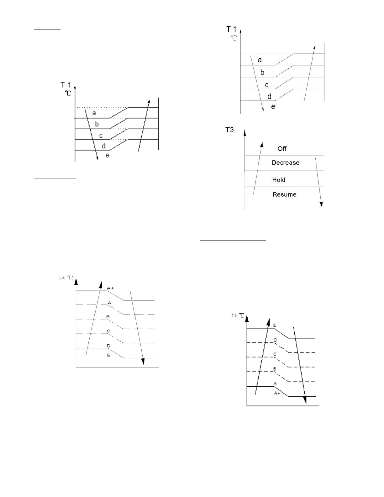
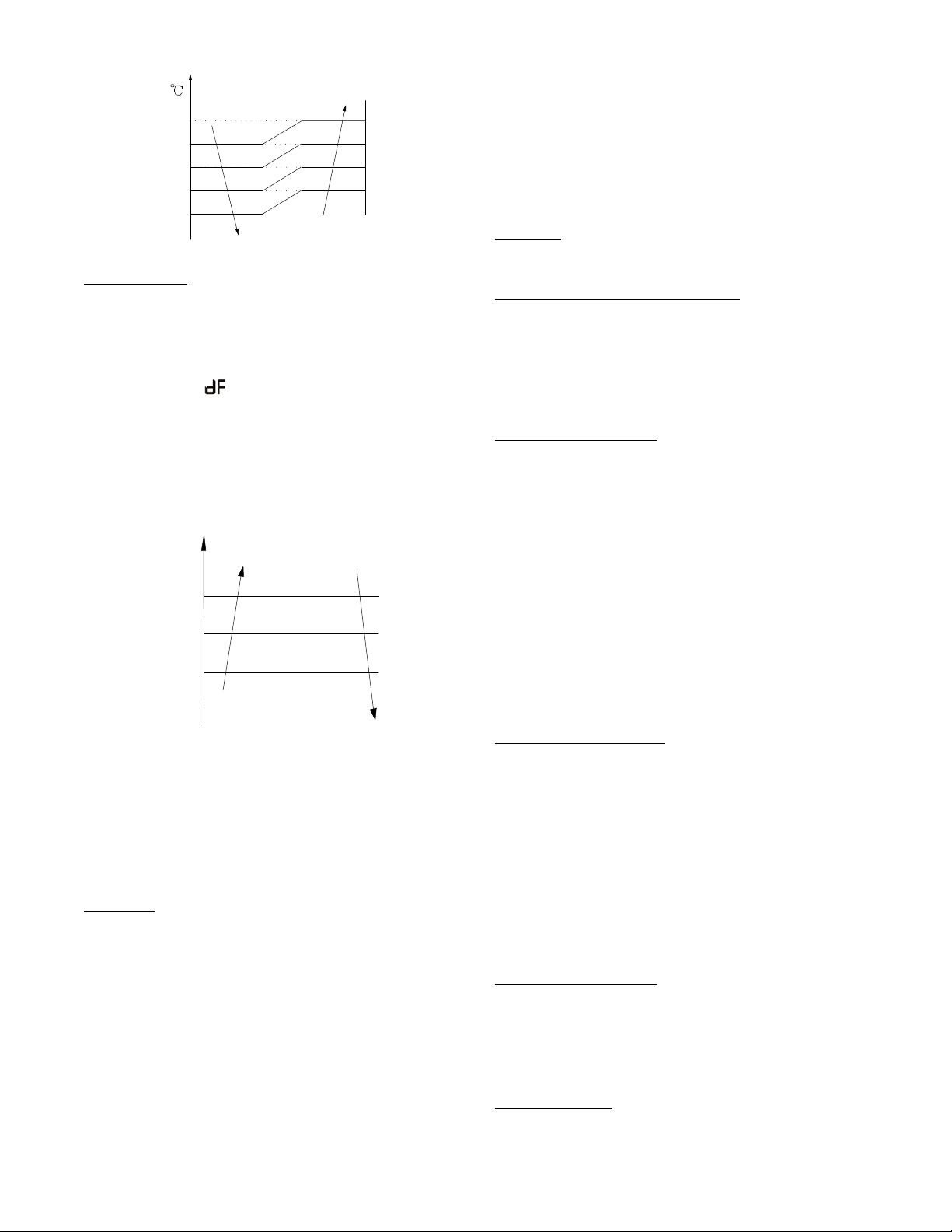
Auto Fan Action in HEATING Mode
a
b
c
d
T1
e
Fig. 23 – Auto Fan Action in HEATING Mode
DEFROST Mode
The air conditioner enters the DEFROST mode according to the
T3 temperature value and the T3 temperature change value range
plus the compressor running time.
During the DEFROST mode, the compressor continues to runs,
the indoor and outdoor motors stop, and the indoor unit defrost
lamp illuminates and
appears.
If any one of the following items is satisfied, the defrosting finishes
and the machine reverts to the normal heating mode.
−−−−T3 rises to be higher than TCDE1_C.
−−−−T3 keeps to be higher than TCDE2_C for 80 seconds.
−−−−The machine has run for 15 minutes in defrosting mode.
Evaporator Coil Temperature Protection
TEstop
T2
Resume
Off
Decrease
TEdown
TEH2
Hold
Fig. 24 – Evaporator Coil Temperature Protection
NOTE: The following applies to Fig. 24:
S Off: Compressor stops
S Decrease: Decrease the running frequency to the lower level
S Hold: Keep the current frequency
S Resume: No limitation for frequency
When the evaporator temperature is higher than the setting
protection value, the compressor stops.
Auto−Mode
This mode can be chosen with the remote controller and the setting
temperature can be changed between 62.6_F(17_C)~86_F(30_C).
In the AUTO mode, the machine chooses the COOLING,
HEATING or FAN−ONLY mode according to ΔT (ΔT =T1−Ts).
Table 13—Auto Mode
ΔT=T1-Ts
Running mode
ΔT>2_C
Cooling
-2≤ΔT≤2_C
Fan-only
ΔT<-2_C
Heating
The indoor fan runs under auto fan in the relevant mode. The louver
operates the same in the relevant mode. If the machine switches modes
between HEATING and COOLING, the compressor stops for 15
minutes and then chooses the mode according to T1−Ts. If the setting
temperature is modified, the machine chooses the running function
again.
DRY mode
Indoor fan speed is fixed at breeze and can not be changed.
The louver angle is the same as in the cooling mode.
Low indoor room temperature protection
In the DRYING mode, if the room temperature is lower than 50_F
(10_C), the compressor stops and does not resume until the room
temperature exceeds 53.6_F (12_C).
Evaporator anti*freezing protection, condenser high temperature
protection and outdoor unit frequency limit are active and are the
same as that in the cooling mode. The outdoor fan operates the
same as in cooling mode.
Forced Operation Function
S Enter forced operation function: When the machine is
off, press Touch to engage the the Forced Auto Mode.
Press Touch again, within 5 seconds, to engage the
Forced Cooling Mode. In Forced Auto, forced cooling
or any other operation mode, press the touch button to
turn off the unit. In the forced operation mode, all
general protections and remote control are available.
Operation rules:
S Forced Cooling Mode: The compressor runs at the F2
frequency and the indoor fan runs as a breeze. After
running for 30 minutes, the unit enters the auto mode as
75.2_F (24_C) setting temperature.
S Forced Auto Mode: The forced auto mode is the same
as the normal auto mode with a 75.2_F (24_C) setting
temperature.
AUTO−RESTART Function
The indoor unit is equipped with the AUTO−RESTART
function, which is carried out through an auto−restart module. In
the event of a sudden power failure, the module memorizes the
setting conditions prior to the power failure. The unit resumes the
previous operation setting (not including the SWING function)
automatically three (3) minutes after the power returns.
If the memorization condition is the FORCED COOLING mode,
the unit will run in the COOLING mode for 30 minutes and turn
to the AUTO mode at the 75.2_F(24_C) setting temperature.
If the air conditioner is off before the power turns off and the air
conditioner is required to start up, the compressor delays start up
for 1 minute before powering on. In other instances, the
compressor waits three (3) minutes before restarts.
Refrigerant Leak Detection
With this new technology, the display area displays “EC” when the
outdoor unit detects a refrigerant leak. This function is only active in
cooling mode. It can better prevent the compressor being damaged by
refrigerant leakage or compressor overload.
Open Condition: When the compressor is active, the value of the Coil
temperature of evaporator T2 has no change or very little change.
46
_F (8_C) Heating
When the compressor is running, the indoor fan motor runs
without the ANTI−COLD air function. When the compressor is
off, the indoor fan motor is off.

22
Point Check Function
Press the remote controller’s LED DISPLAY or LED or MUTE button three times, and then press the AIR DIRECTION or SWING
button three times in ten seconds, the buzzer rings for two seconds. The air conditioner enters into the information enquiry status.
Press the LED DISPLAY or AIR DIRECTION button to check the next or front item’s information.
When the air conditioner enters the information enquiry status, it displays the code name in 2 seconds (see Table 14).
Table 14—Information Enquiry
ENQUIRY INFORMATION
DISPLAYING CODE MEANING
T1 T1 T1 temp.
T2 T2 T2 temp.
T3 T3 T3 temp.
T4 T4 T4 temp.
T2B Tb T2B temp.
TP TP TP temp.
TH TH TH temp.
Targeted Frequency FT Targeted Frequency
Actual Frequency Fr Actual Frequency
Indoor Fan Speed IF Indoor fan speed
Outdoor Fan Speed OF Outdoor fan speed
EXV Opening Angle LA EXV opening angle
Compressor continuous running time CT Compressor continuous running time
Compressor stop causes ST Compressor stop causes
Reserve A0
Reserve A1
Reserve b0
Reserve b1
Reserve b2
Reserve b3
Reserve b4
Reserve b5
Reserve b6
Reserve dL
Reserve Ac
Reserve Uo
Reserve Td
When the air conditioner enters the information enquiry status, it displays the code value for 25 seconds (see Table 15).
Table 15—Information Enquiry
ENQUIRY
INFORMATION
DISPLAY VALUE MEANING REMARK
T1,T2,T3,T4,
T2B,TP,TH,
Targeted
Frequency,
Actual
Frequency
-1F,-1E,-1d,-1c,
-1b,-1A
-25,-24,-23,-22,-21,-20
1. The displaying temperature is the actual value.
2. The temperature is _C no matter what kind of remote
controller is used.
3. T1,T2,T3,T4,T2B display range:-25~70, TP display
range:-20~130.
4. Frequency display range: 0~159HZ.
5. If the actual value exceeds the range, it displays the
maximum value or minimum value.
-19—99 -19—99
A0,A1,…A9 100,101,…109
b0,b1,…b9 110,111,…119
c0,c1,…c9 120,121,…129
d0,d1,…d9 130,131,…139
E0,E1,…E9 140,141,…149
F0,F1,…F9 150,151,…159
Indoor fan speed
/Outdoor fan speed
0 OFF
1,2,3,4
Low speed, Medium speed, High
speed, Turbo
For some big capacity motors.
14-FF
Actual fan speed = Display value
turns to decimal value and then
multiply 10. The unit is RPM.
For some small capacity motors, the display value is from 14-FF
(hexadecimal), the corresponding fan speed range
is from 200-2550 RPM.
EXV opening angle 0-FF
Actual EXV opening value =
Display value turns to decimal
value and then multiply 2.
Compressor
continuous running
time
0-FF 0-255 minutes
If the actual value exceeds the range, it displays the
maximum value or minimum value.
Compressor stop
causes
0-99
For the detailed meaning, please
consult with engineer
Decimal display
Reserve 0-FF
23
TROUBLESHOOTING
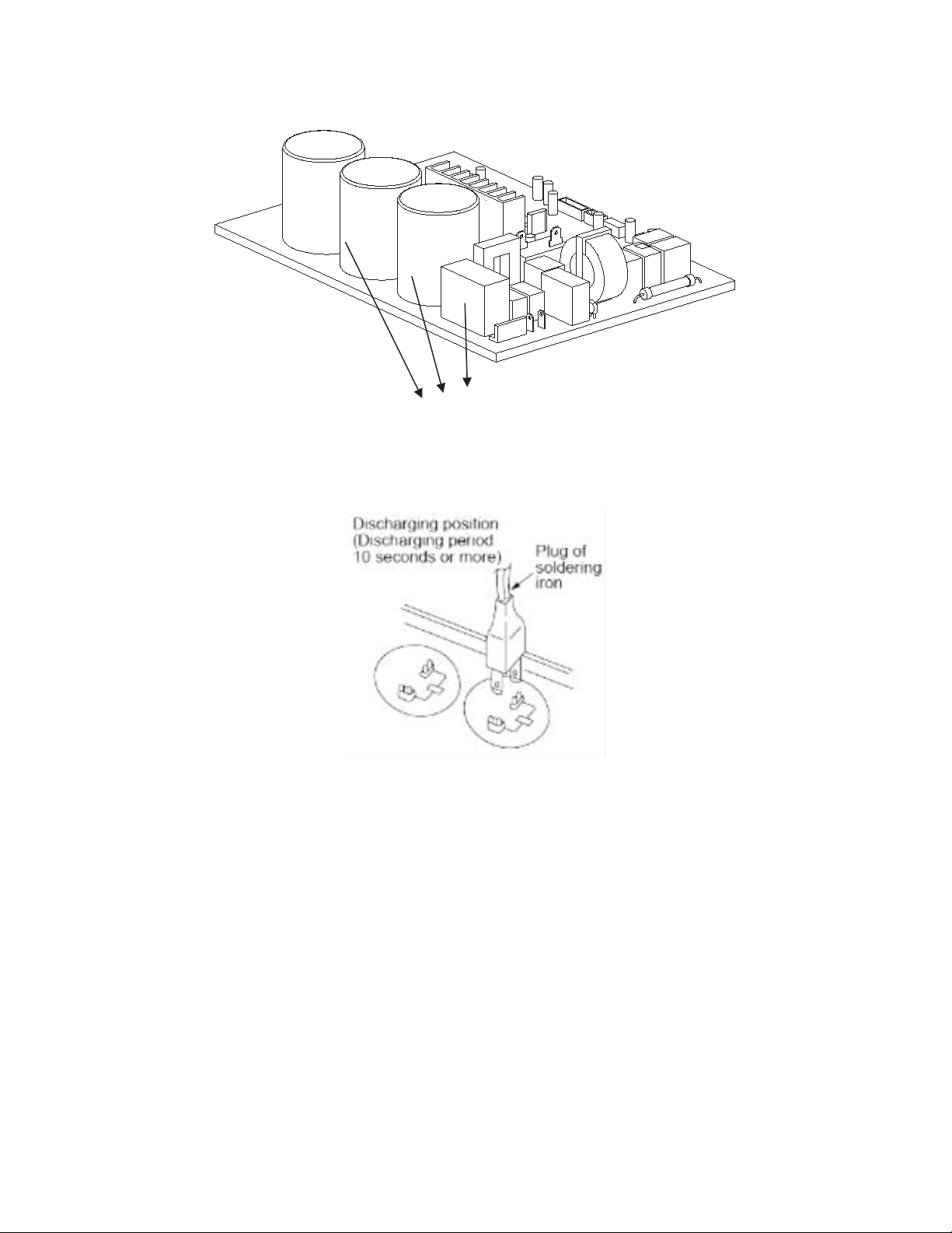
Safety
Electricity power is kept in capacitors even if the power supply is shut off.
NOTE: Remember to discharge the electricity power in capacitor.
Electrolytic Capacitors
(HIGH VOLTAGE! CAUTION!)
Fig. 25 – Electrolytic Capacitors
For other models, please connect discharge resistance (approximately 100Ω 40W) or a soldering iron (plug) between the +, − terminals of the
electrolytic capacitor on the contrary side of the outdoor PCB.
Fig. 26 – Discharge Position
NOTE: Fig. 26 is for reference only. The plug on your unit may differ.

24
OUTDOOR UNIT DIAGNOSTIC GUIDES
Table 16—Diagnostic Guides
OPERATION LAMP
TIMER LAMP DISPLAY LED STATUS
☆1 time
X E0 Indoor unit EEPROM parameter error
☆ 2 times
X E1 Indoor / outdoor units communication error
☆ 3 times
X E2 Zero-crossing signal detection error
☆ 4 times
X E3 Indoor fan speed has been out of control
☆ 5 times
X E4 Indoor room temperature sensor T1 open circuit or short circuit
☆ 6 times
X E5 Evaporator coil temperature sensor T2 open circuit or short circuit
☆ 7 times
X EC Refrigerant leakage detection
☆ 1 time
O F0 Overload current protection
☆ 2 times
O F1 Outdoor ambient temperature sensor T4 open circuit or short circuit
☆ 3 times
O F2 Condenser coil temperature sensor T3 open circuit or short circuit
☆ 4 times
O F3 Compressor discharge temperature sensor T5 open circuit or short circuit
☆ 5 times
O F4 Outdoor unit EEPROM parameter error
☆ 6 times
O F5 Outdoor fan speed has been out of control
☆ 1 time ☆
P0 IPM malfunction or IGBT over-strong current protection
☆ 2 times ☆
P1 Over voltage or over low voltage protection
☆ 3 times ☆
P2 High temperature protection of IPM module or compressor top
☆ 4 times ☆
P3* Outdoor ambient temperature too low.
☆ 5 times ☆
P4 Inverter compressor drive error
☆ 6 times ☆
P5 Indoor units mode conflict (multi-zone ONLY)
O(light) X(off) ☆(flash)
25
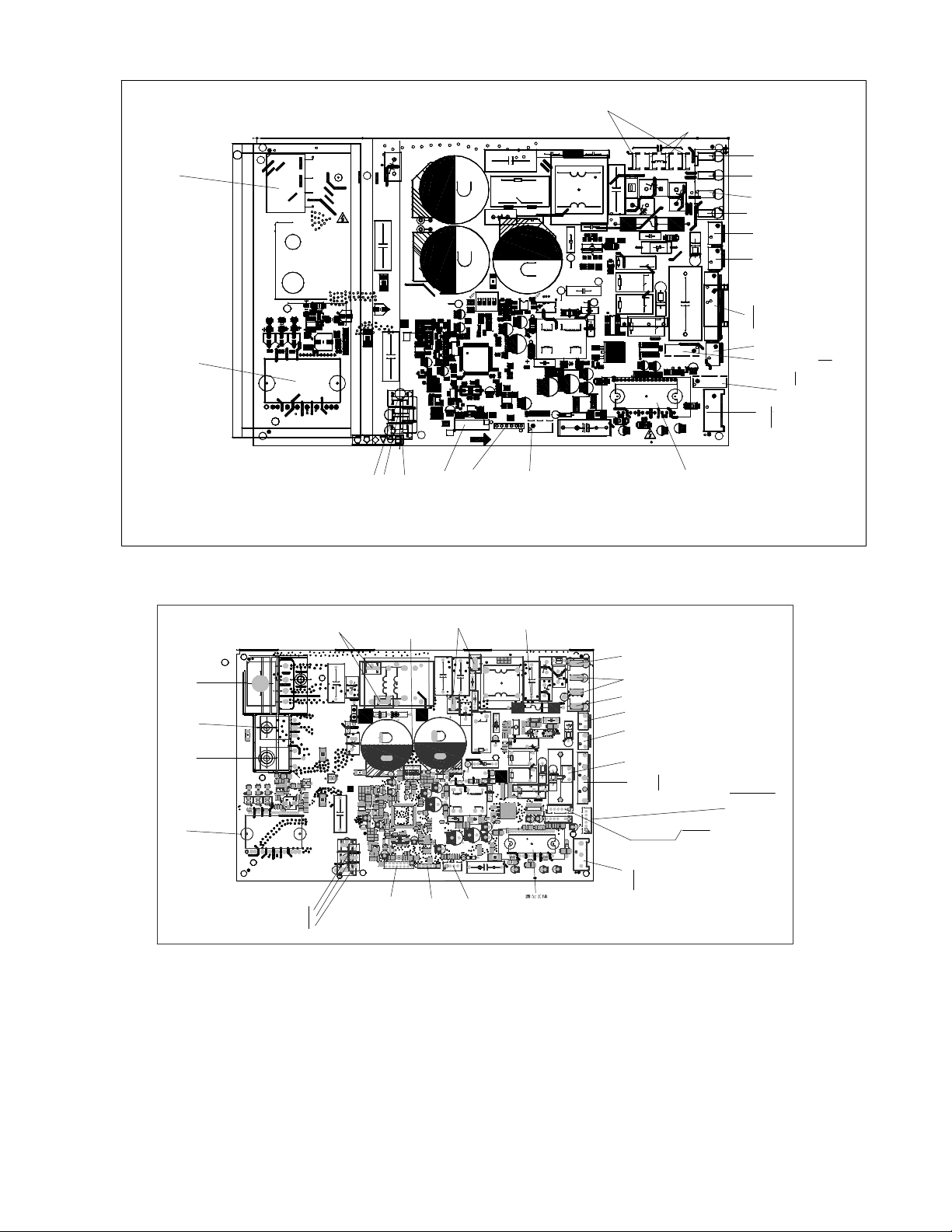
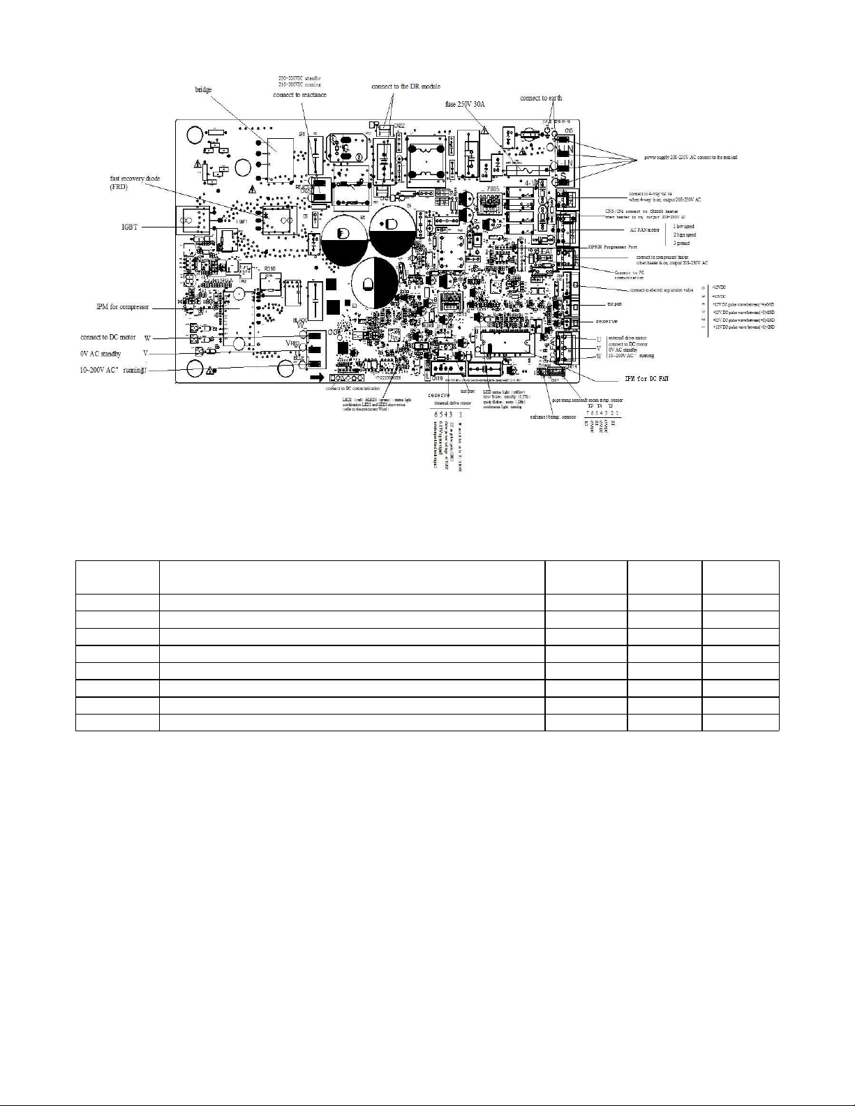
PCB DIAGRAMS
N
1
17122000019195
1
1
[1.6] 2015−09−30
US−KFR−35W/BP3N1−(115V+RX62T+41560).D.13.WP2−1
L−IN N−IN
7805
S
HEAT1
4−WAY
AC−FAN
HEAT2
Earth
DC−FAN
PMV
TESTPORT
BLACK
W
RED
V
BLUE
U
CN4_1CN4_2
CN4_3CN4_4
REACTOR
CAP
T3T4
TP
N
N
N
H
L
CN25
CN31
AC
AC
+
−
BR1
+
E2
CN21
RC1
E304
ZR2
+−
AC
OUTIN
~~
RY3A
SJ−S−112DMG
R191
IC105
CN15
ZR5
ZR4
R628
C618
R118
R123
R122
C324
IC2
R421
R621
D103
C413
C306
C319
IPM301
R176
R175
+
E109
C107
T401
R410
R409
R316
3W−10m¦,¡À1%
D407
+
+
C110
R623
R602
C624
RY3
R196
D610
C318
C316 C314
C134
+
E605
E303
E208
E206
E302
E300
CN50
R523
R522
R521
R520
R519
R518
R517
R323
R322
R321
R320
R319
R318
R317
IC301
C513
C512
C511
C323
C321
C320
R426
R314
R306
R305
R304
R303
C311
C310
C309
C308
C307
CN28
CN29
CN30
C520
C1
+
E106
C101
D101
C611
R171
D602
IC102
Rdi
D404
D401
CN6
ZR1
RY2
R626
R620
R619
R618
R617
R616
R615
R612
R611R610
R608
R607
R605
R603
R601
R528
R516
R513
R508
R506
R504
R502
R429
R428
R427
R408
R407
R406
R405
R404
R403
R315
R301
R190
R188
R187
R186R185
R182
R181
R180
R179
R178
R174
R173
R170
R169
R168
R165
R157
R155
R154
R152
R150
R149
R148
R147
R144
R143
R142
R140
R138
R137
R136
R135
R133
R132
R131
R130
R129
R128
R127
R126
R125
R124
R121
R120
R117
R116
R115
R114
R112
R111
R110
R108
R107
R106
R105
R102
R101
R2
Q101
OSC101
NTC2
+
LED101
IC603
IC602
IC601
IC403
IC401
IC1
+
E602
+
E401
+
E108
+
E107
+
E105
+
E103
+
E102
+
E101
+
E1
+
E3
+
DZ601
DZ304 DZ303
DZ302
DZ301
+
DZ203
+
DZ202
D406
D402
+
D2
+
D1
1
CN505
CN7
C615
C614
C612
C606
C605
C601
C509
C508
C507
C506
C505
C504
C503
C412
C410
C409
C408
C405
C404
C402
C401
C322
C312
C305
C303
C302
C274
C273
C272
C271
C133
C132
C131
C130
C129
C128
C127
C126
C125
C124
C123
C121
C120
C119
C118
C116
C115
C114
C113
C112
C111
C106
C105
C104
C103
C102
C16
C11 C10
C7
C6
C5
C4
C3
C2
+ E280
+
E281
+
E282
+
E283
+
E404
+
E407
PTC1
+
E409
D104
R401
R103
C117
R195
R172
+
DZ204
C275
R156
R604
R104
IC101
IC104
RY4
+
E410
+
E405
FUSE1
T20A/250VAC
C9A
CN1A
IC404
+
D403
IC103
C613
CN3
CN2
CN1
CN16
+
DZ201
L2
L3
L4L5
C135
CN17
R21 R23
RY5
21
4
3
3
4
ON
12
ON
SW2
RC2
DSA1
IC405
+
CN60
C8
L1
R1
IPM501
C122
Comment
Comment
RY1
CN507
R606
3W−10m¦,¡À1%
R253
0.75 ¦,/1W
R254
0.75 ¦,/1W
connect to compressor heater
when is on, 100−130V AC output
connect to 4−way Valve
when is on, 100−130VAC OUTPUT
connect to PFC Capacitor
when is on, 100−130V AC
output
connect to reactor
when is on, 100−130V AC output
connect to
Ground
connect to N−line
(100−130VAC INPUT)
connect to L−line
(100−130VAC INPUT)
connect to indoor unit
communication
U
V
W
10− 230VAC¡¯ (running)
0VAC (standby)
connect to DC Motor
external driver motor
connect to Electric Expansion Valve
pipe temp.sensor& room temp.
sensor&Exaust temp. sensor
6 5 4 3 2 1
TP T4 T3
RT
RT
+5VDC
RT
+5VDC
+5VDC
+12V DC pulse wave between (+1)−GND
+12V DC pulse wave between (+2)−GND
+12V DC pulse wave between (+3)−GND
+12V DC pulse wave between (+4)−GND
+12V DC
+12V DC
6 5 4 3 2 1
AC fan motor
5
4
3
2
1
low speed
N line
high speed
FAN Starting Capacitor
FAN Starting Capacitor
connect to chassis heater
when is on, 100−130VAC OUTPUT
UV
W
0VAC(standby)
10−230VAC¡¯(running)
connect to
compressor
connect to PC
communication
EEPROM Programmer
Port
Test Port
bridge
IPM for compressor
IPM for DC FAN
P
Fig. 27 – Size 12 115V
+
T4TP
T3
N
L
H
N
N
Rdi
Have
Low−Fre
YES
NO
No
U
BLUE
V
RED
W
BLACK
TESTPORT
PMV
DC−FAN
DR_L
DR_N
Earth
HEAT2
AC−FAN
4−WAY
HEAT1
S
7805
N−INL−IN
KFR−35W/BP3N1−(RX62T+41560).D.13.WP2−1
[1.8] 2015−12−31
1
1
17122000002718
1
E304
E208
C10
RC3
CN22
ZR4
R696
R695
C696
C695
ZR5
C9
IPM501
L1
C8
CN60
+
IC405
DAS1
RC2
ON
21
ON
4
3
3
4
1
2
SW2
RY5
R23R21
CN17
CN11
CN10
C135
L5L4L3L2
+
DZ201
L601
CN16
CN1
CN2
CN3
CN3_1
C613
IC103
CN507
+
D403
IC404
CN1A
FUSE1
T20A/250VAC
E405
E410
RY4
IC104
IC101
R104
R604
R156
C275
DZ204
R172
R195
C117
R103
R401
D104
E409
PTC1
CN32
BR1
E407
E404
E283
+ E282
+
E281
+
E280
RY 1
D601
Q601
C2
C3
C4
C5
C6
C7
C11
C16
C102
C103
C104
C105
C106
C111
C112
C113
C114
C115
C116
C118
C119
C120
C121
C123
C124
C125
C126
C127
C128
C129
C130
C131
C132
C133
C271
C272
C273
C274
C302
C303
C305
C312
C322
C401
C402
C404
C405
C408
C409
C410
C503
C504
C505
C506
C507
C508
C509
C601
C605
C606
C612
C614
C615
CN7
CN9
CN31
CN505
D1D2
D402
D406
DZ202
DZ203
DZ301
DZ302
DZ303
DZ304
DZ601
E1
E2
E101
E102
E103
E105
E107
E108
E401
E602
IC1
IC401
IC403
IC601
IC602
IC603
LED101
NTC2
OSC101
Q101
R2
R3
R101
R102
R105
R106
R107
R108
R110
R111
R112
R114
R115
R116
R117
R120
R121
R124
R125
R126
R127
R128
R129
R130
R131
R132
R133
R135
R136
R137
R138
R140
R142
R143
R144
R147
R148
R149
R150
R152
R154
R155
R157
R165
R168
R169
R170
R173
R174
R178
R179
R180
R181
R182
R185
R186
R187
R188
R189
R190
R301
R315
R403
R404
R405
R406
R407
R408
R427
R428
R429
R502
R504
R506
R508
R513
R516
R528
R601
R603
R605
R607
R608
R610R611
R612
R615
R616
R617
R618
R619
R620
R626
RY2
ZR1
CN6
D401
D404
Rdi
IC102
D602
R171
C611
D101
C101
E106
C1
C520
ZR3
CN30
CN29
CN28
C307
C308
C309
C310
C311
R303
R304
R305
R306
R314
R426
C320
C321
C323
C511C512
C513
IC301
R317
R318
R319
R320
R321
R322
R323
R517
R518
R519
R520
R521
R522
R523
CN50
E206
E605
C134
C314C316
C318
CN25
D610
R196
RY3
C624
R602
R623
C110
C122
D407
R316
3W− 10m|??¨¤1%
R409
R410
R606
3W−10m1%
T401
C107
E109
R175
R176
IPM301
C319
C306
C413
D103
R621
R421
IC2
C324
R122
R123
R118
C618
R628
CN15
IC105
R191
RY3A
ZR2
RC1
CN21
R1
C412
E300
E302
E303
C330
C331
C332
C333
C334
connect to the terminal
208−230V AC
power supply
connect to earth
CN60
connect to 4−way valve
when 4−way is ON, output 208−230VAC
connect to compressor heater
power supply
CN17
AC fan motor
L low speed
N ground
H high speed
CN21/CN22
exhaust temp. sensor& pipe
temp.sensor& room temp.
sensor
6 5 4 3 2 1
TP T4 T3
RT
RT
+5VDC
RT
+5VDC
+5VDC
connect to Electric Expansion Valve
+12V DC pulse wave between (+1)−GND
+12V DC pulse wave between (+2)−GND
+12V DC pulse wave between (+3)−GND
+12V DC pulse wave between (+4)−GND
+12V DC
+12V DC
6 5 4 3 2 1
connect to indoor unit communication
HEAT2
connect to chassis heater
when is on, 208−230VAC OUTPUT
U
V
W
10−200VAC¡¯ (running)
0VAC (standby)
connect to the DC compressor
Test Port
Connect to PC
communication
EEPROM Programmer Port
FUSE1 20A/250VAC
Connect to DR module
U
V
W
10−200VAC¡¯ (running)
0VAC (standby)
connect to DC Motor
External driver motor
LED101 status light (Red)
slow flicker:standby(
0.5Hz)
quick flicker:error( 2Hz)
continuous light: normally running
Connect to reactor
IPM for
compressor
IGBT
FRD
when heater is ON, output 208−230V AC
BR
P
N
Fig. 28 – Sizes 09−12 208−230V
26
PCB DIAGRAMS (CONT)
Fig. 29 – Sizes 18−24 208−230V
NOTE: After power on, LED3(Green color) and LED2(Red color) will flash if the unit has some problems.
Table 17—LED Codes
No.
Problems
LED3
(Green)
LED2
(Red)
IU display
1 standby for normal O X
2 Operation normally X O
3 IPM malfunction or IGBT over-strong current protection ☆ X P0
4 Over voltage or too low voltage protection O O P1
5 EEPROM parameter error O ☆ E5
6 Inverter compressor drive error X ☆ P4
7 Inverter compressor drive error ☆ O P4
8 Inverter compressor drive error ☆ ☆ P4
O(light) X(off) ☆(2.5Hz flash)
27
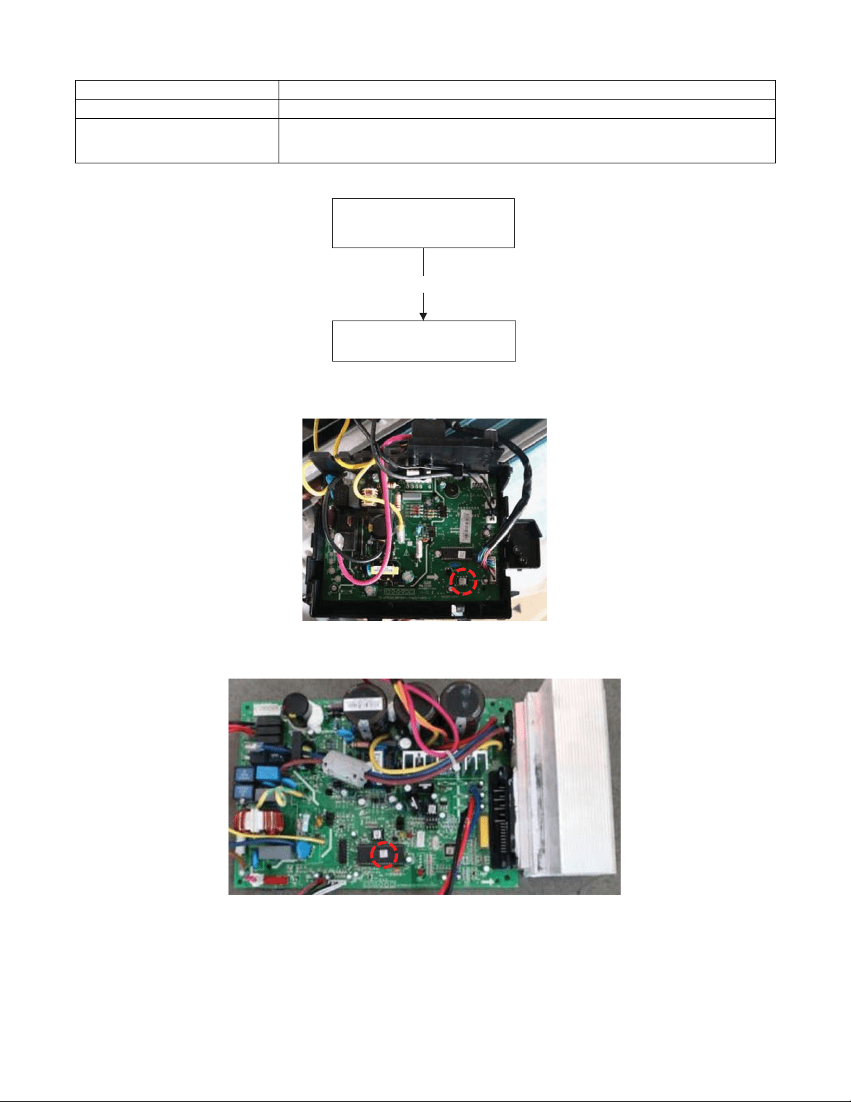
DIAGNOSIS AND SOLUTION
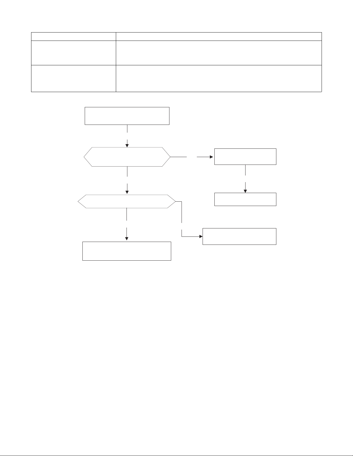
EEPROM Parameter Error Diagnosis and Solution (E0/F4)
Error Code
E0/F4
Malfunction decision conditions Indoor or outdoor PCB main chip does not receive feedback from the EEPROM chip.
Supposed causes
S Installation mistake
S PCB faulty
Troubleshooting
Yes
Replace the indoor/outdoor
main PCB.
Power off, then restart the
unit 2 minutes later.
EEPROM: A read−only memory whose contents can be erased and reprogrammed using a pulsed voltage. For the EEPROM chip location,
please refer to Fig 30 and Fig. 31.
Fig. 30 – Indoor PCB
Fig. 31 – Outdoor PCB
NOTE: The two pictures above are for reference only and they may differ from the actual unit.
28
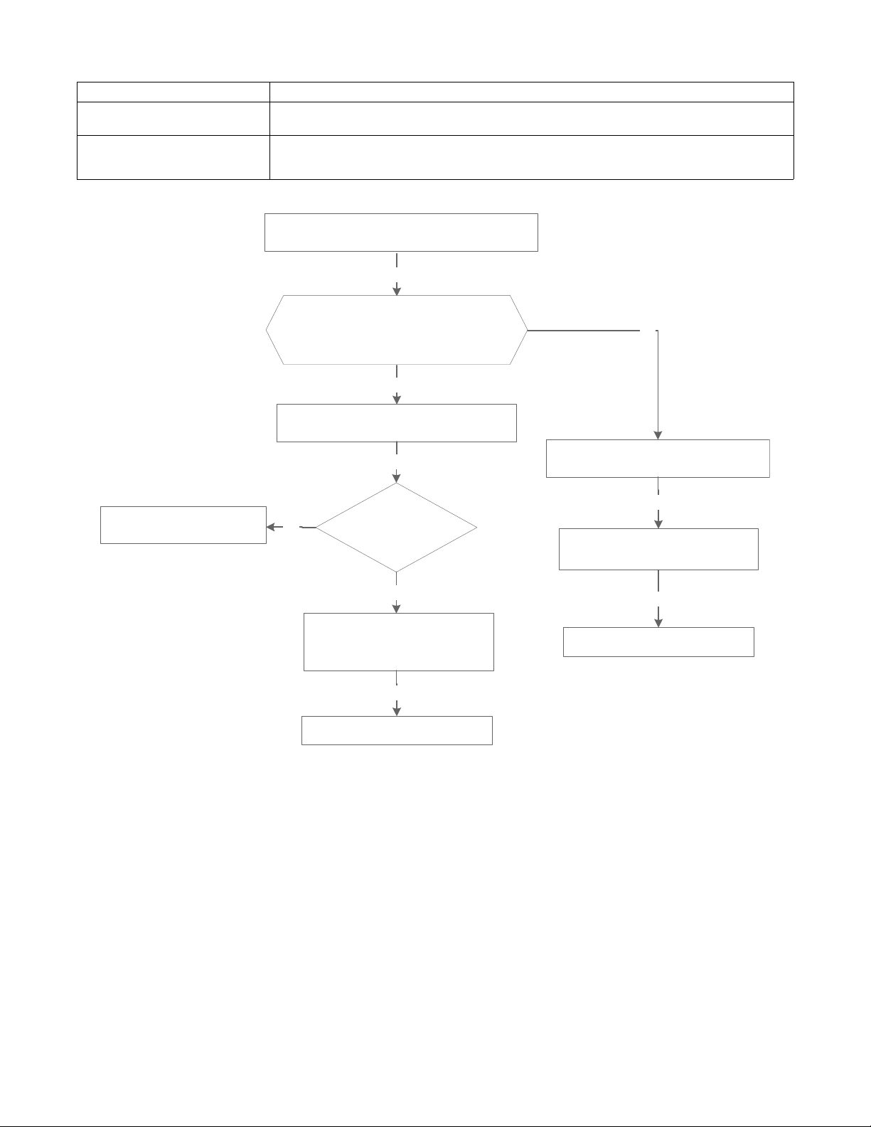
DIAGNOSIS AND SOLUTION (CONT)
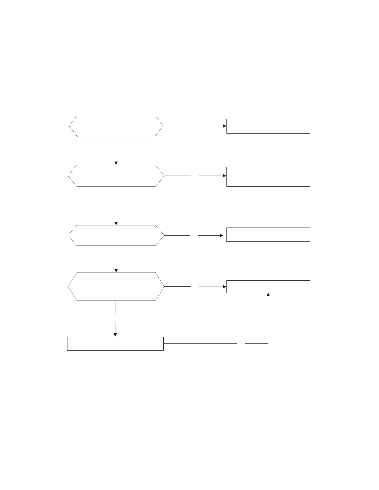
Indoor / outdoor unit’s communication diagnosis and solution (E1)
Error Code
E1
Malfunction Decision Conditions
Indoor unit does not receive the feedback from outdoor unit during 110 seconds and this condition
happens four times continuously.
Supposed Causes
S Wiring mistake
S Indoor or outdoor PCB faulty
Troubleshooting
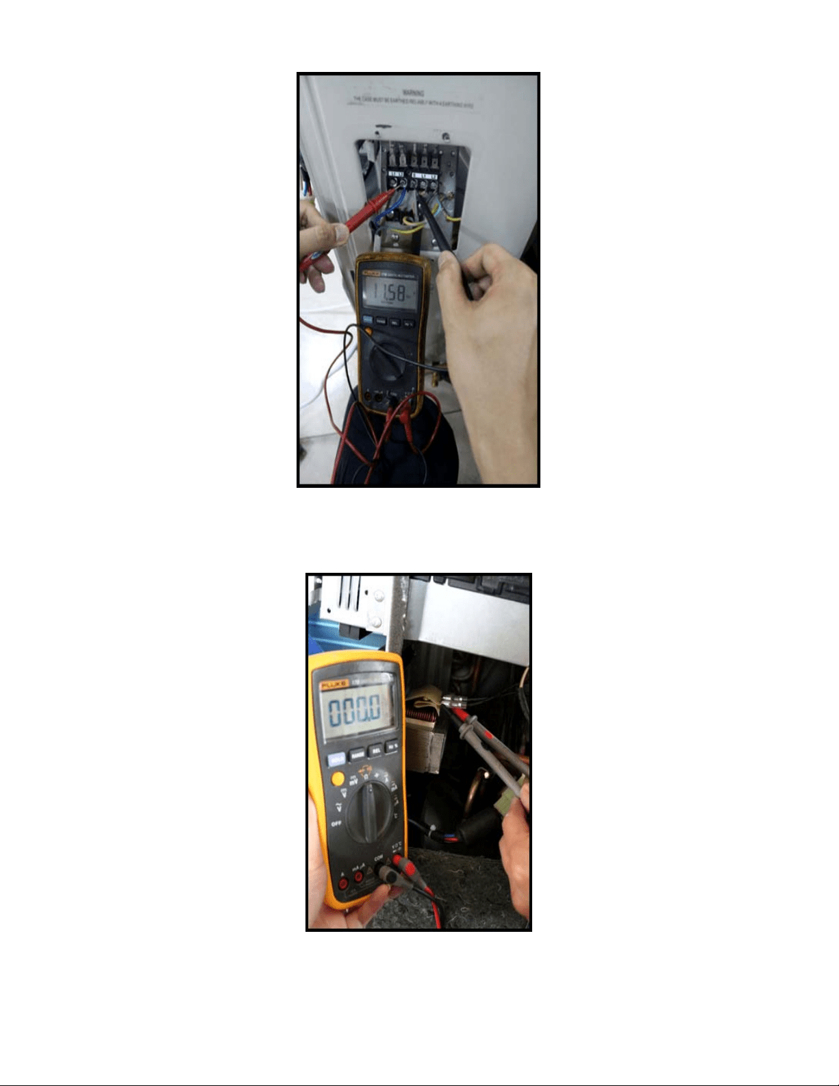
Measure Vs., is it a positive fluctuation?
(Vs represents the voltage S and N of the
outdoor unit. Red pan-S, Black pan-N)
Power off, then restart the unit 2 minutes later
Replace the indoor main PCB.
Power on. Is the error resolved?
No
Check the indoor wiring connection
Yes
Check whether the
reactor is normal
Yes
No
Check the outdoor wiring connection
Replace the reactor
Yes
Replace the outdoor main PCB.
Power on. Is the error resolved?
Replace the indoor main PCB
No
Replace the outdoor main PCB.
Yes
No
Yes
Yes
29
DIAGNOSIS AND SOLUTION (CONT)
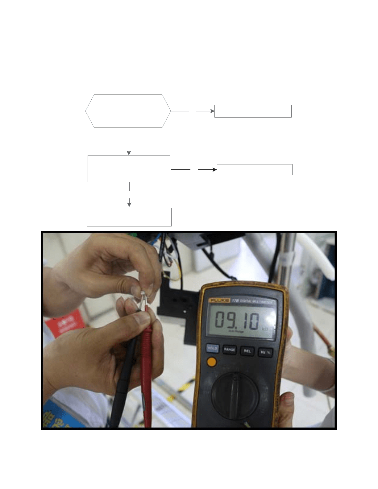
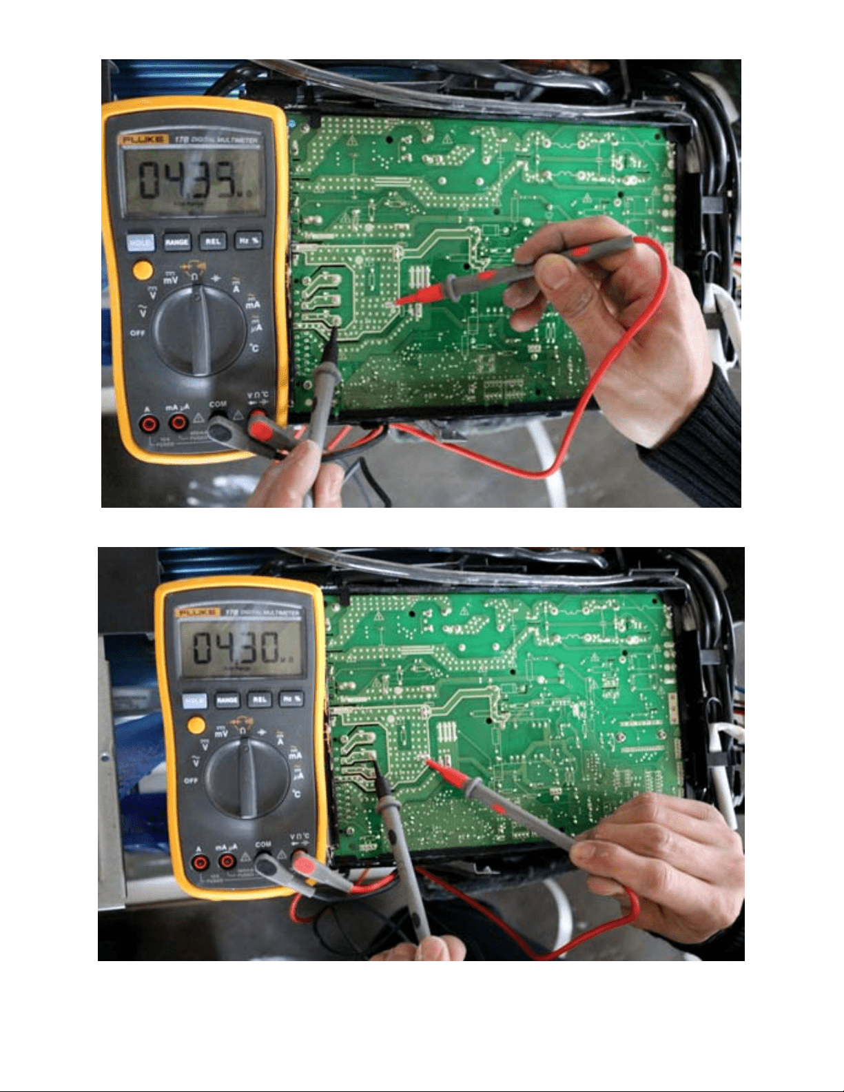
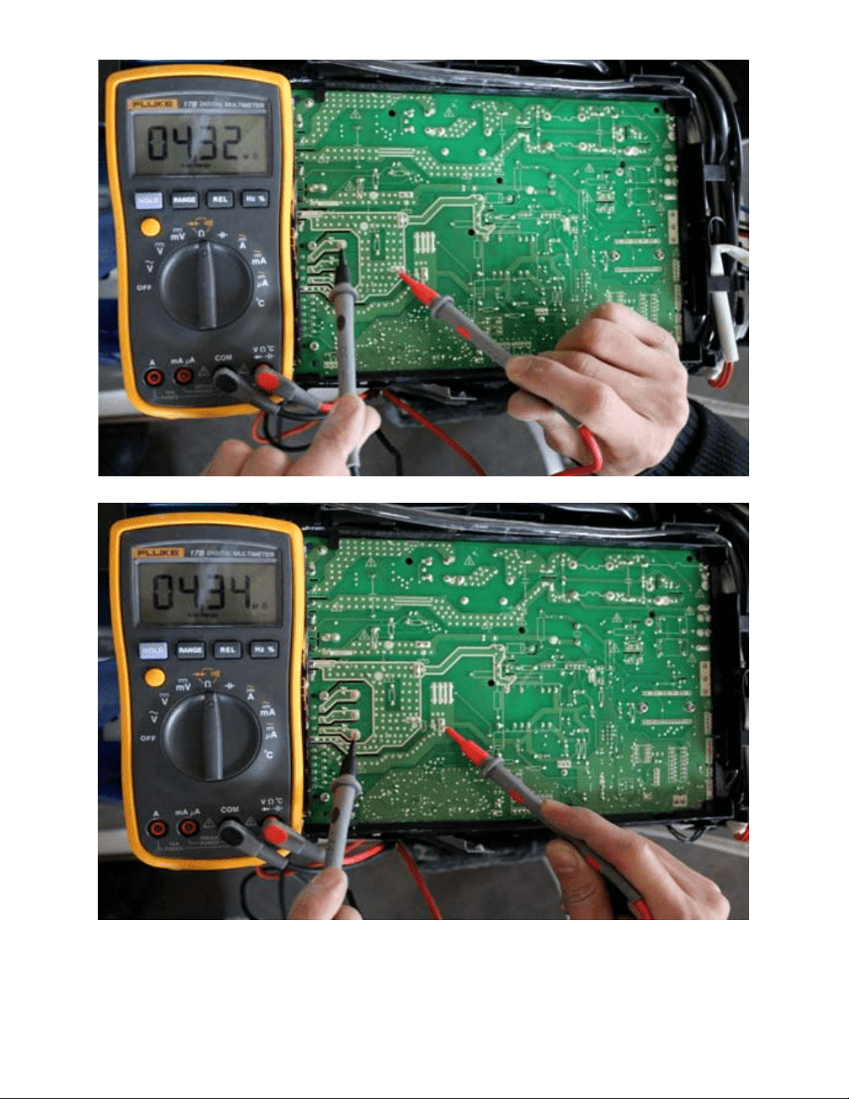
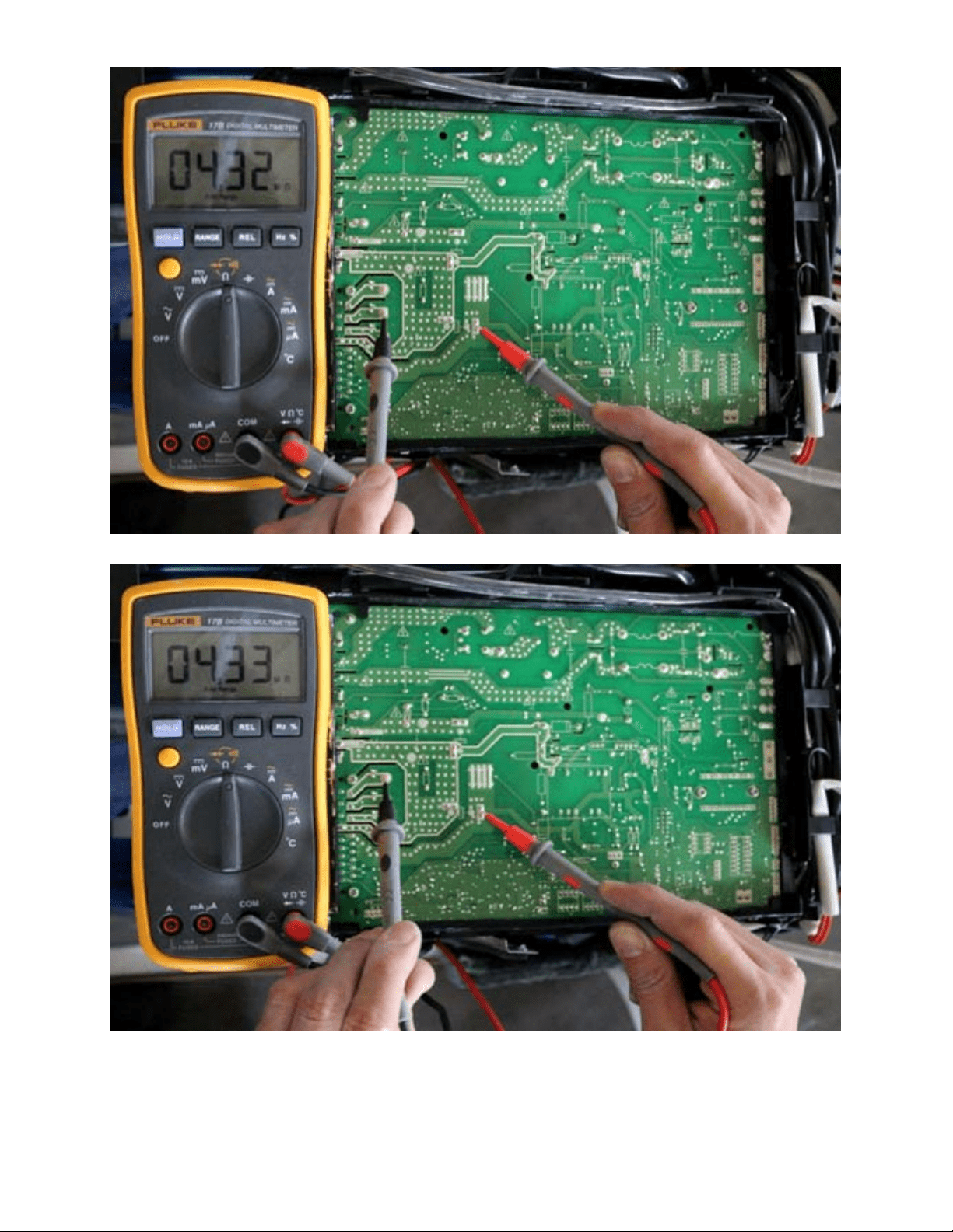
Fig. 32 – Test the DC Voltage
Use a multimeter to test the DC voltage between L2 port and S port of the outdoor unit. The red pin of the multimeter connects with the L2
port while the black pin is for the S port. When air conditioner is running normal, the voltage moves alternately between −50V to 50V. If the
outdoor unit has a malfunction, the voltage will move alternately with positive value. If the indoor unit has malfunction, the voltage will have
a certain value.
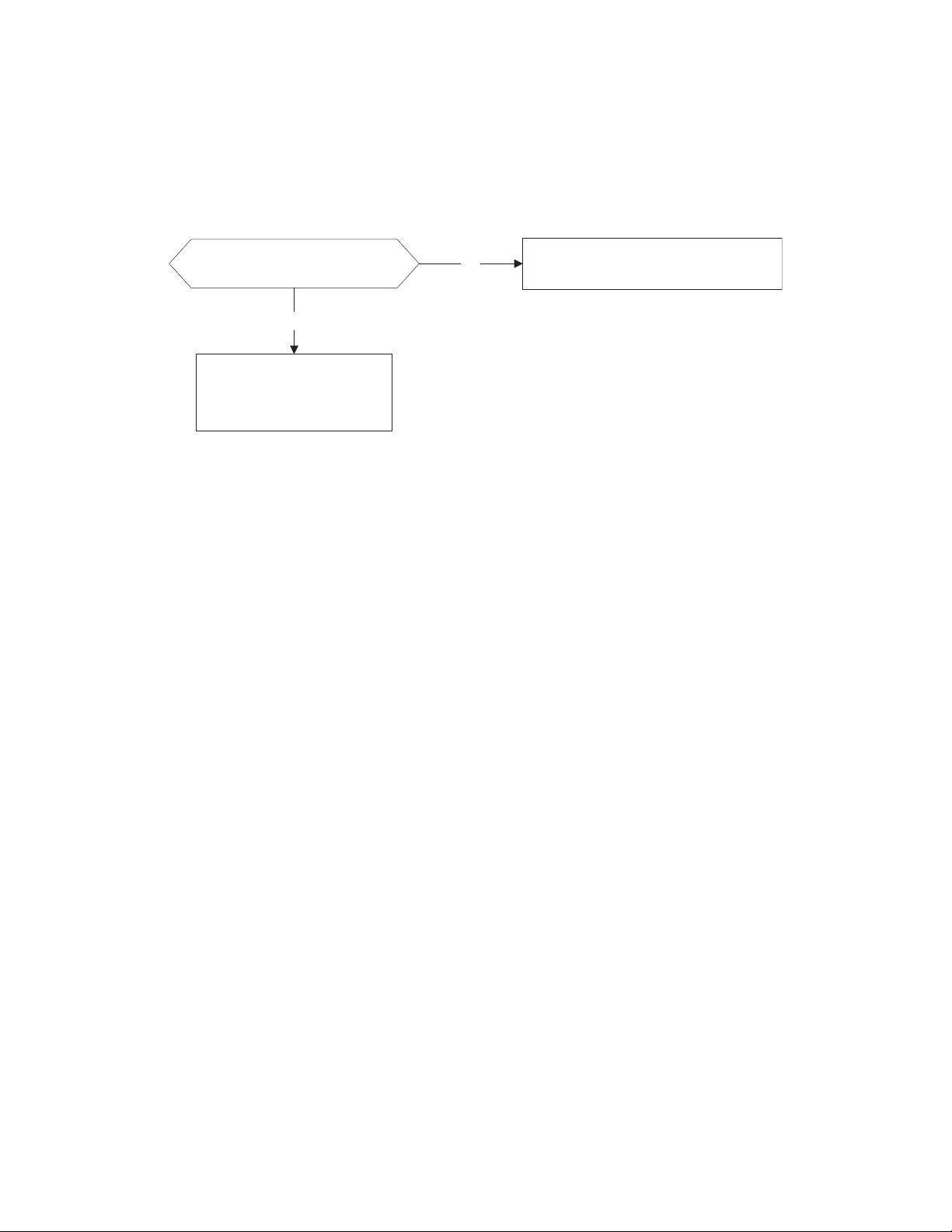
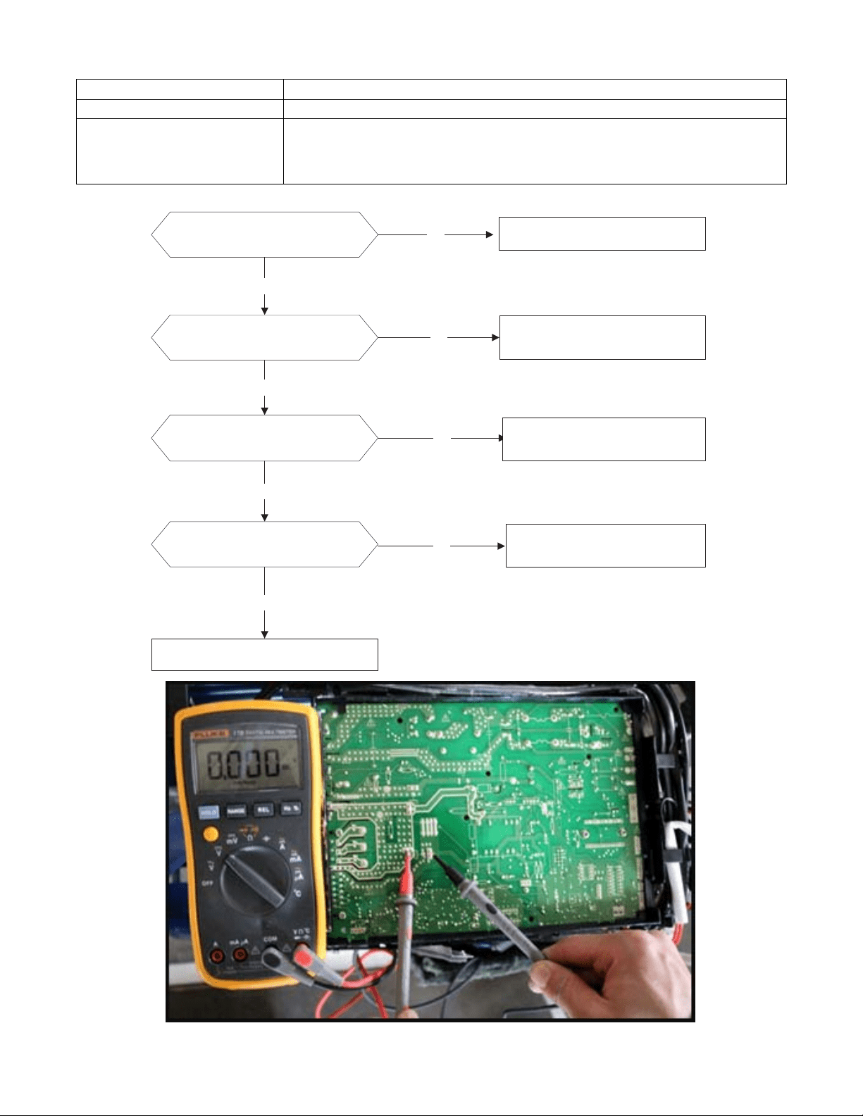
Fig. 33 – Test the Reactor Resistance
Use a multimeter to test the resistance of the reactor which does not connect with the capacitor. The normal value should be around zero (0)
ohm. Otherwise, the reactor has a malfunction and needs to be replaced.
30
DIAGNOSIS AND SOLUTION (CONT)
Zero crossing detection error diagnosis and solution (E2)
Error Code
E2
Malfunction decision conditions
When the PCB does not receive a zero crossing signal feedback for 4 minutes or the zero crossing
signal time interval is abnormal.
Supposed causes
S Connection mistake
S PCB faulty
Troubleshooting
Check if the connections and
power supply are normal.
Correct the connections. Turn on the
unit when the power supply is good.
No
Yes
Indoor main PCB is
defective. Replace indoor
main PCB.
31
DIAGNOSIS AND SOLUTION (CONT)
Fan speed has been out of control diagnosis and solution (E3/F5)
Error Code
E3/F5
Malfunction decision conditions
When indoor fan speed remains too low (300RPM) for certain time, the unit stops and the LED
displays the failure.
Supposed causes
S Wiring mistake
S Fan assembly faulty
S Fan motor faulty
S PCB faulty
Troubleshooting
Power off, then restart the
unit 2 minutes later
Shut off the power supply,
Rotate the fan by hand.
The unit operates normally.
Find the cause and resolve it.
Check the fan motor wiring
No
Yes
No
Correct the connections.
No
No
Replace the fan motor
Yes
Yes
Measure the voltage for the
fan motor from the main
PCB
Yes
Replace the main PCBNo
32
DIAGNOSIS AND SOLUTION (CONT)
Index 1
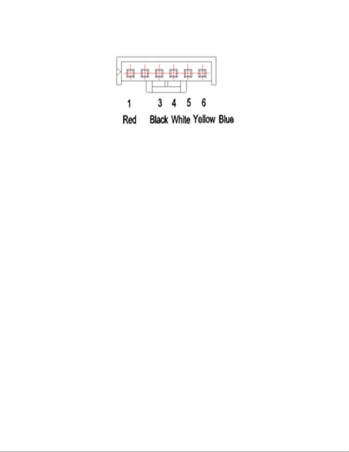
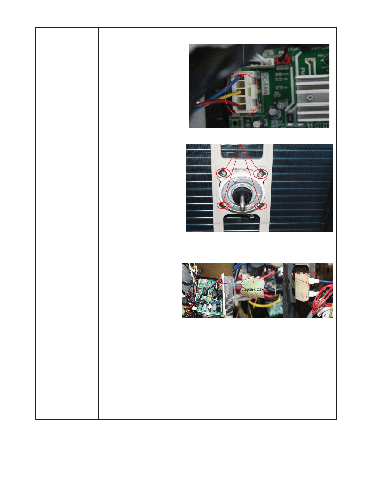
1 Indoor or Outdoor DC Fan Motor (control chip is in fan motor)
S Power on and when the unit is in standby, measure the voltage of pin1−pin3, pin4−pin3 in fan motor connector. If the voltage value
is not in the range shown in Table 18 or Table 19, the PCB has an issue and needs to be replaced.
Fig. 34 – Motor Connector
Table 18—DC motor voltage input and output (voltage: 220−240V~)
NO.
COLOR SIGNAL VOLTAGE
1 Red Vs/Vm 280V~380V
2 --- --- ---
3 Black GND 0V
4 White Vcc 14-17.5V
5 Yellow Vsp 0~5.6V
6 Blue FG 14-17.5V
Table 19—DC motor voltage input and output (voltage : 115V~)
NO. COLOR SIGNAL VOLTAGE
1 Red Vs/Vm 140V~190V
2 --- --- ---
3 Black GND 0V
4 White Vcc 14-17.5V
5 Yellow Vsp 0~5.6V
6 Blue FG 14-17.5V
2 . Outdoor DC Fan Motor (control chip is in the outdoor PCB)
S Power on the unit and check if the fan runs normally. If the fan runs normally, the PCB has an issue and needs to be replaced. If the
fan does not run normally, measure the resistance of each two pins. If the resistance is not equal to each other, the fan motor has an
issue and needs to be replaced, otherwise the PCB has an issue and needs to be replaced.
3 Indoor AC Fan Motor
S Power on the unit and set the unit in FAN mode at the high fan speed. Run for 15 seconds then measure the voltage of pin1 and
pin2. If the voltage value is less than 100V(208~240V power supply) or 50V(115V power supply), the PCB has an issue and needs
to be replaced.
33
DIAGNOSIS AND SOLUTION (CONT)
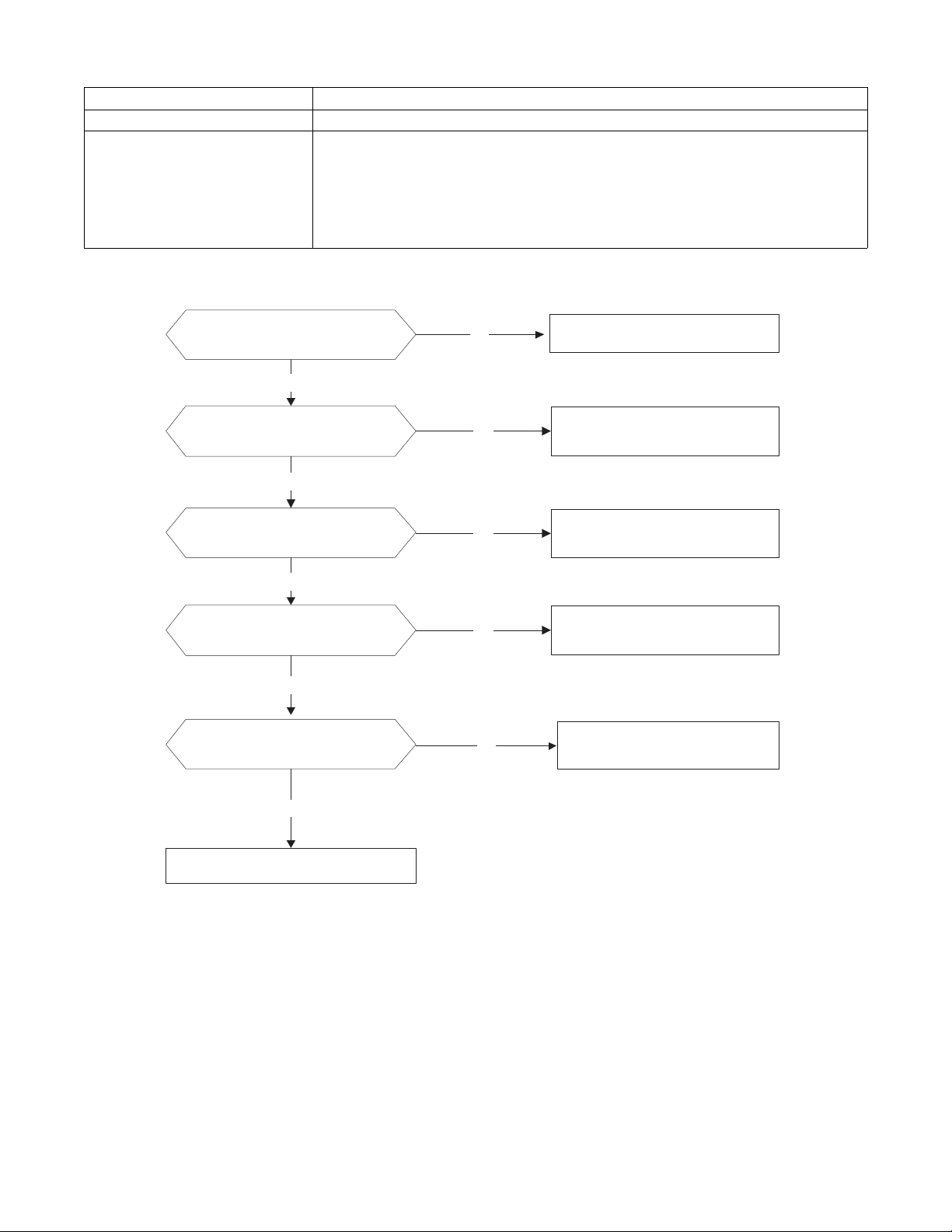
Open circuit or short circuit of temperature sensor diagnosis and solution (E4/E5/F1/F2/F3)
Error Code
E4/E5/F1/F2/F3
Malfunction decision conditions If the sampling voltage is lower than 0.06V or higher than 4.94V, the LED displays the failure.
Supposed causes
S Wiring mistake
S Sensor faulty
S PCB faulty
Troubleshooting
Check the connection
between the temperature
sensor and PCB.
Correct the connectionNo
Yes
Replace indoor or outdoor
main PCB
Measure the resistance
value of the sensor
Replace the sensorNo
Yes
Fig. 35 – Check the connection
34
DIAGNOSIS AND SOLUTION (CONT)
Refrigerant Leakage Detection diagnosis and solution (EC)
Error Code
EC
Malfunction decision conditions
Define the evaporator coil temp.T2 of the compressor. It starts running in Tcool.
At first, 5 minutes after the compressor starts up, if T2 <Tcool-35.6_F (Tcool-2 _C) does not
run for 4 seconds and this situation occurs 3 times, the display area displays“EC”and the air
conditioner will turn off.
Supposed causes
S T2 sensor faulty
S Indoor PCB faulty
S System problems, such as leakage or blocking.
Troubleshooting
Check cool air blowing out
from indoor air outlet
Yes
Yes
No
Check for system leaks
No
Power off, then restart the
unit 2 minutes later.
Replace indoor PCB
.
Yes
Repair the leakage and
recharge the refrigerant.
Yes
Check for system blocking and
clear the block
Check the T2 sensor
35
DIAGNOSIS AND SOLUTION (CONT)
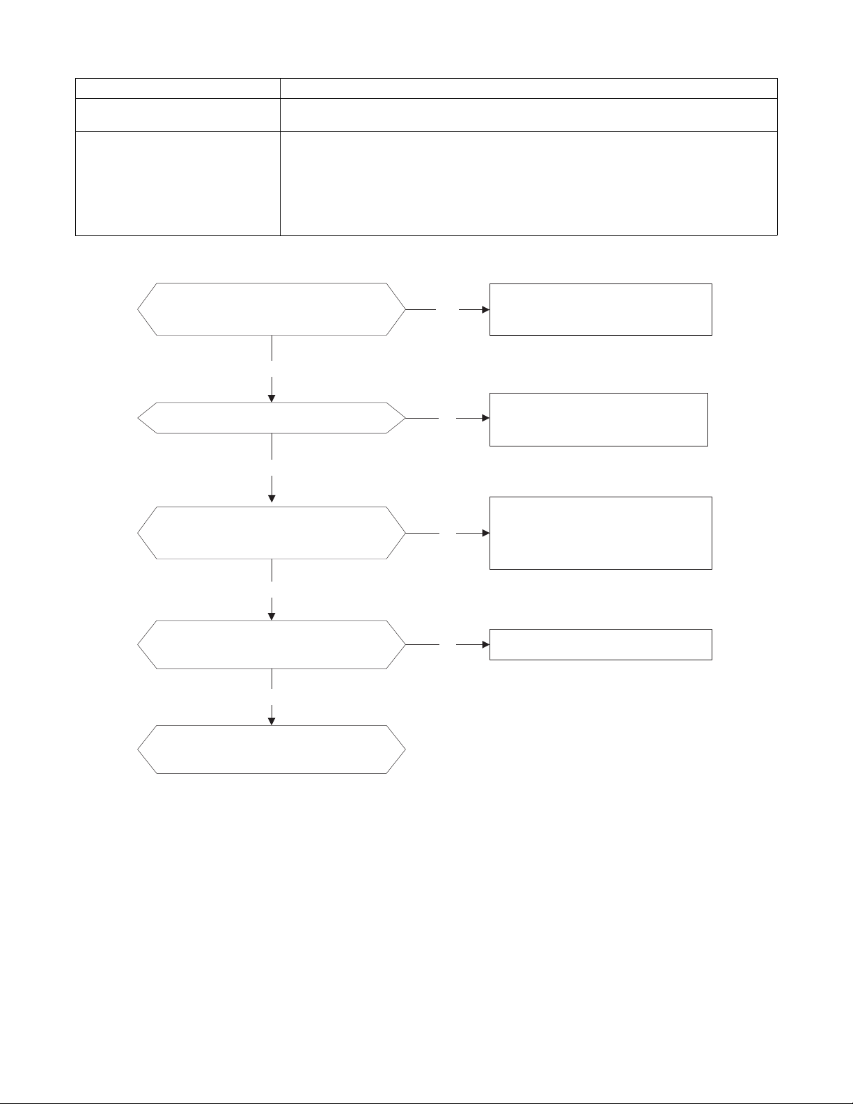
Overload current protection diagnosis and solution (F0)
Error Code
F0
Malfunction decision conditions An abnormal current rise is detected by checking the specified current detection circuit.
Supposed causes
S Power supply problems
S System blockage
S PCB faulty
S Wiring mistake
S Compressor malfunction
Troubleshooting
Check the power supply
Check the connections and
wires
Stop the unit
No
Yes
No
Correct the connections or
replace the wires.
Yes
Replace the outdoor unit
Yes
Check the reactor
No
Replace outdoor main PCB
Check for system blockage
Yes
No Clear the blockage
Check the compressor
resistance values
Yes
No
Replace the compressor
36
DIAGNOSIS AND SOLUTION (CONT)
IPM malfunction or IGBT over−strong current protection diagnosis and solution (P0)
Error Code
P0
Malfunction decision conditions
When the voltage signal, that the IPM sends to the compressor drive chip is abnormal, the display
LED displays P0”and the air conditioner turns off.
Supposed causes
S Wiring mistake
S IPM malfunction
S Outdoor fan assembly faulty
S Compressor malfunction
S Outdoor PCB faulty
Troubleshooting
Check the wiring between main the
PCB and the compressor
Correct the connection or replace
the wires and connectors.
Yes
No
Check the IPM No
Yes
Replace the IPM board or replace
the main PCB
Check the outdoor fan and the
outdoor unit ventilation
No
Please refer to the solution of ǏFan
Speed Has Been Out Of Controlǐ
malfunction
Yes
Check the compressor resistance
values
No
Replace the compressor.
Yes
Replace the outdoor main PCB
37
DIAGNOSIS AND SOLUTION (CONT)
Fig. 36 – P−U
Fig. 37 – P−V
38
DIAGNOSIS AND SOLUTION (CONT)
Fig. 38 – P−W
Fig. 39 – N−U
39
DIAGNOSIS AND SOLUTION (CONT)
Fig. 40 – N−V
Fig. 41 – N−W
40
DIAGNOSIS AND SOLUTION (CONT)
Over voltage or too low voltage protection diagnosis and solution (P1)
Error Code
P1
Malfunction decision conditions An abnormal voltage rise or drop is detected by checking the specified voltage detection circuit.
Supposed causes
S Power supply problems
S System leakage or block
S PCB faulty
Troubleshooting
Check the power supply
Check the connections and
wires
Stop the unit
No
Yes
No
Correct the connections or
replace the wires.
Yes
Replace the reactor
Yes
No
Replace the IPM board
Check the voltage between P
and N
Check the reactor
Yes
No
Replace outdoor main PCB
Fig. 42 – Test
NOTE: Measure the DC voltage between the P and N port. The normal value should be around 310V.
41
DIAGNOSIS AND SOLUTION (CONT)
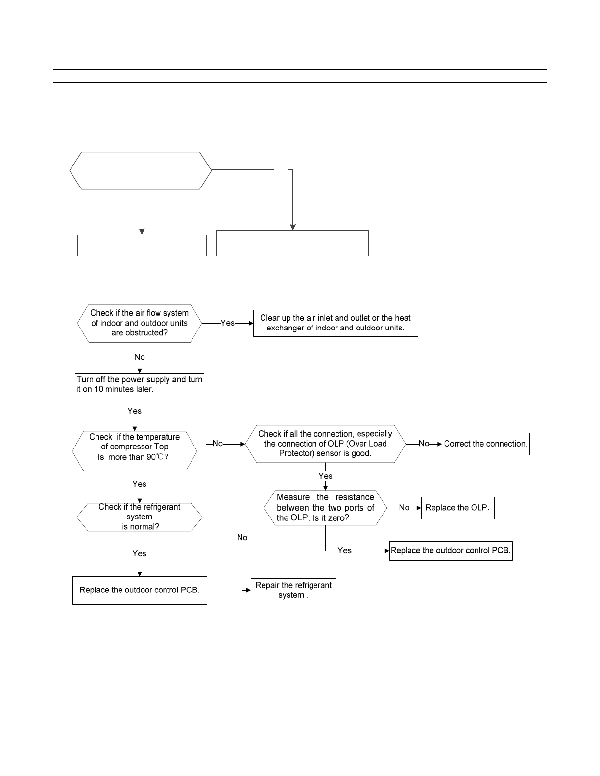
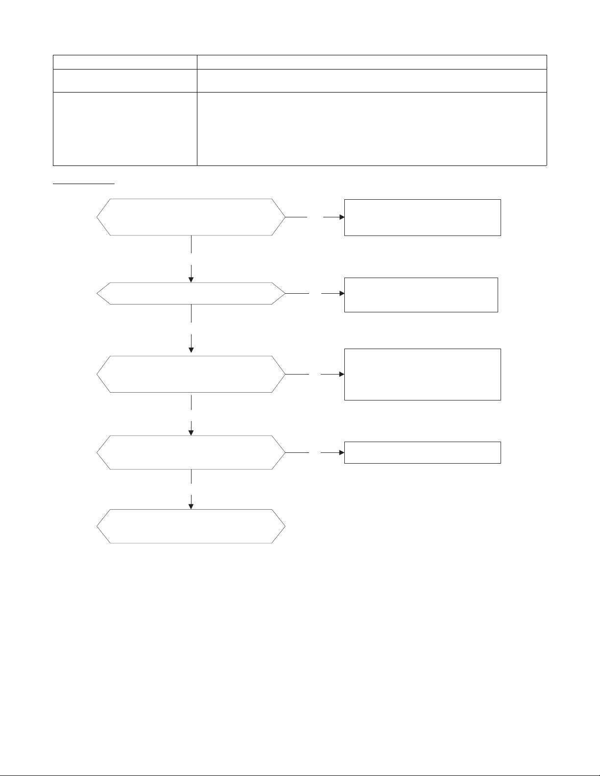
High temperature protection of compressor top diagnosis and solution (P2)
Error Code
P2
Malfunction decision conditions If the sampling voltage is not 5V, the LED displays the failure.
Supposed causes
S Power supply problems
S System leakage or block
S PCB faulty
Troubleshooting
Yes
Tighten the screws and apply
silicon grease.
Replace the outdoor control PCB.
No
Check if the Fastening screws
on the PCB and IPM radiator
are fixed tightly.
For other models,
42
DIAGNOSIS AND SOLUTION (CONT)
Inverter compressor drive error diagnosis and solution (P4)
Error Code
P4
Malfunction decision conditions
An abnormal inverter compressor drive is detected by a special detection circuit, including
communication signal detection, voltage detection, compressor rotation speed signal detection, etc.
Supposed causes
S Wiring mistake
S IPM malfunction
S Outdoor fan assembly faulty
S Compressor malfunction
S Outdoor PCB faulty
Troubleshooting
Check the wiring between main PCB
and compressor
Correct the connection or replace
the wires and connectors.
Yes
No
Check the IPM
No
Yes
Replace the IPM board or replace
the main PCB
Check the outdoor fan and the
outdoor unit ventilation
No
Please refer to the solution of ǏFan
Speed Has Been Out Of Controlǐ
malfunction
Yes
Check the compressor resistance
values
No Replace the compressor.
Yes
Replace the outdoor main PCB
43
DIAGNOSIS AND SOLUTION (CONT)
Main Parts Check
Temperature Sensor Checking
Disconnect the temperature sensor from the PCB, measure the resistance value with a tester.
Fig. 43 – Tester
Temperature sensors.
Room temp.(T1) sensor,
Indoor coil temp.(T2) sensor,
Outdoor coil temp.(T3) sensor,
Outdoor ambient temp.(T4) sensor,
Compressor discharge temp.(T5) sensor.
Measure the resistance value of each winding by using the multi−meter.
44
DIAGNOSIS AND SOLUTION (CONT)
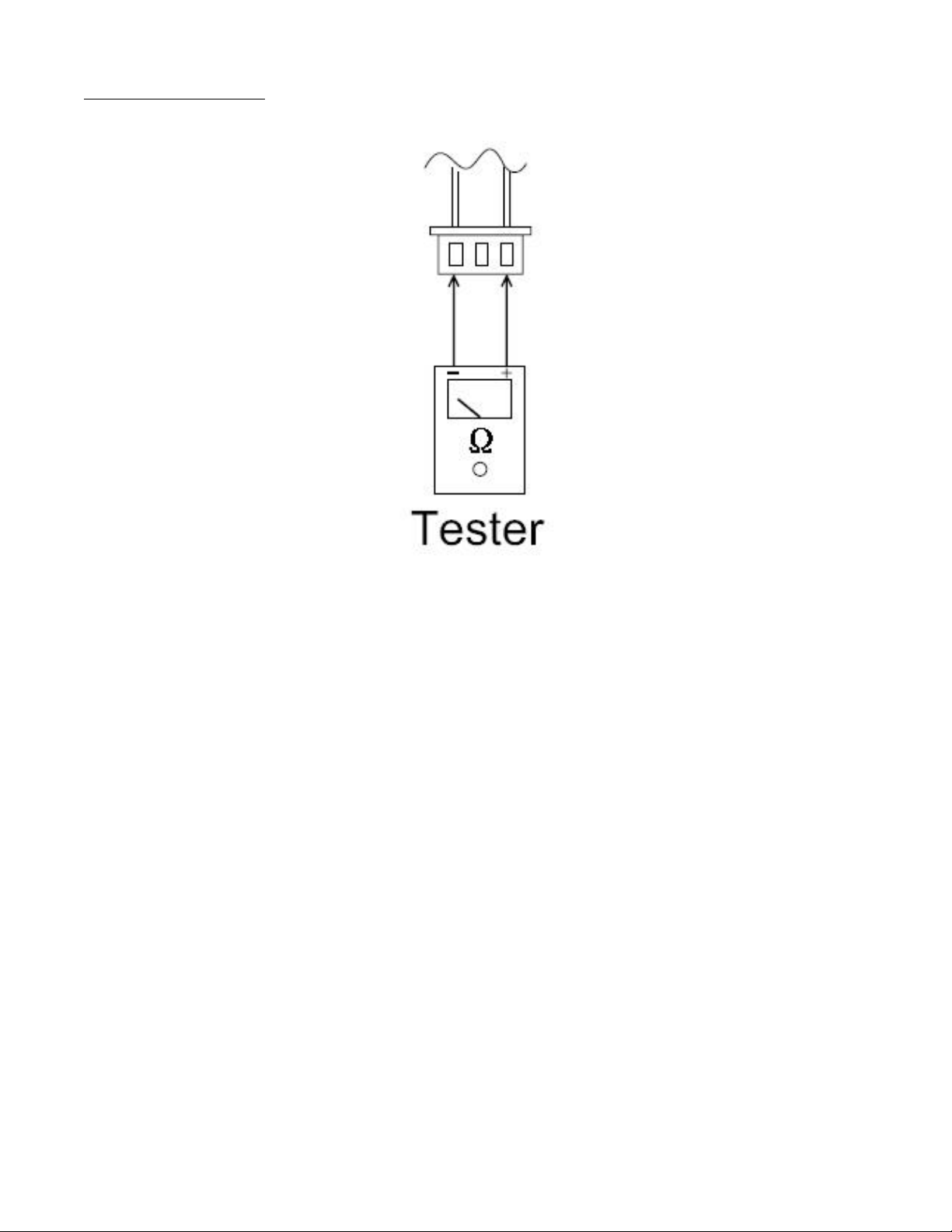
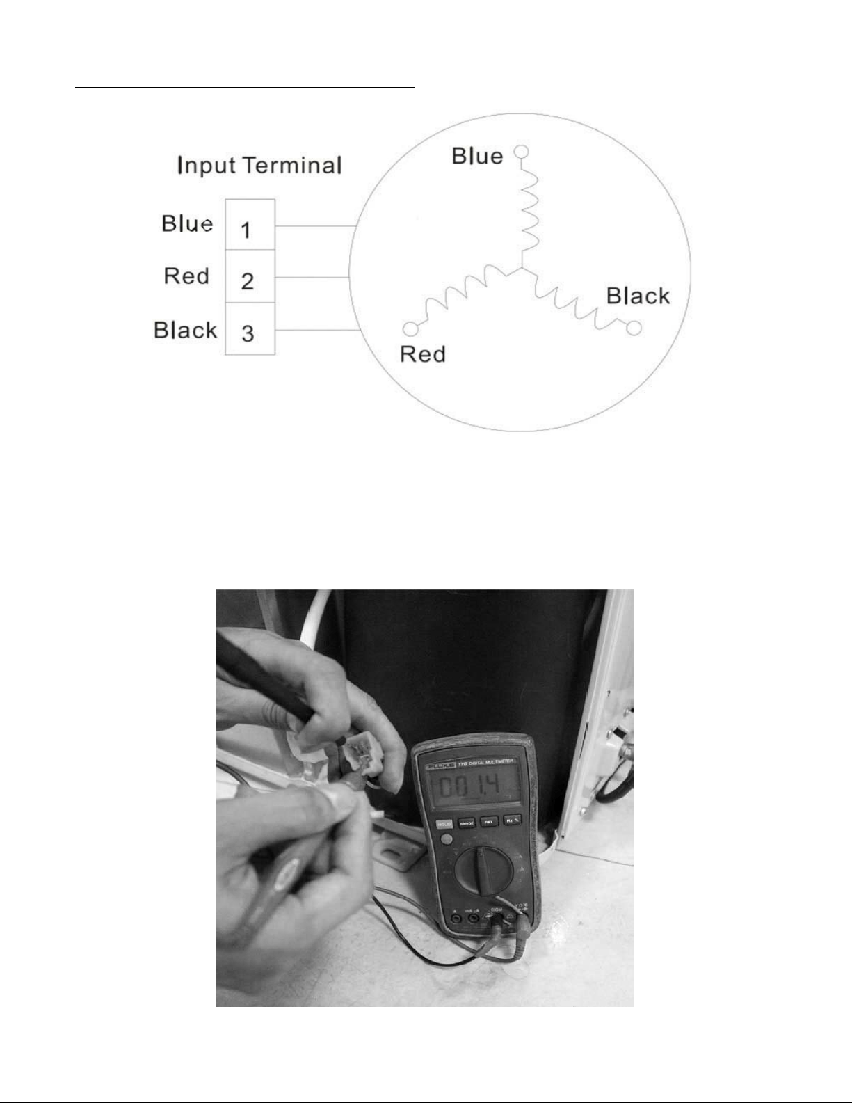
Compressor Checking
Measure the resistance value of each winding by using the tester.
Fig. 44 – Tester
Table 20—Compressor Checking
Position
Resistance Value
ASN98D22UFZ ASM135D23UFZ ATF235D22UMT ATF250D22UMT
Blue - Red
1.57Ω 1.75 Ω 0.75 Ω 0.75 ΩBlue - Black
Red - Blue
Fig. 45 – Compressor Checking

45
DIAGNOSIS AND SOLUTION (CONT)
IPM Continuity Check
Turn off the power, let the large capacity electrolytic capacitors discharge completely, and dismount the IPM. Use a digital tester to measure
the resistance between P and UVWN; UVW and N.
Table 21—IPM Continuity Check
Digital Tester
Normal Resistance Value Digital Tester Normal Resistance Value
(+)Red (-)Black
∞
(Several MΩ)
(+)Red (-)Black
∞
(Several MΩ)
P
N U
N
U V
V W
W (+)Red
Fan Motor
Measure the resistance value of each winding by using the tester.
Table 22—Fan Motor
Model
YKT-32-6-202L YKT-32-6-3L YKT-48-6-206 YKT-63-6-200L
Brand Tongde Welling Welling Welling
Black – Red (Main)
Ω 86 213 152 88.5
Blue –Black (AUX)
Ω 64 156 142 138
46
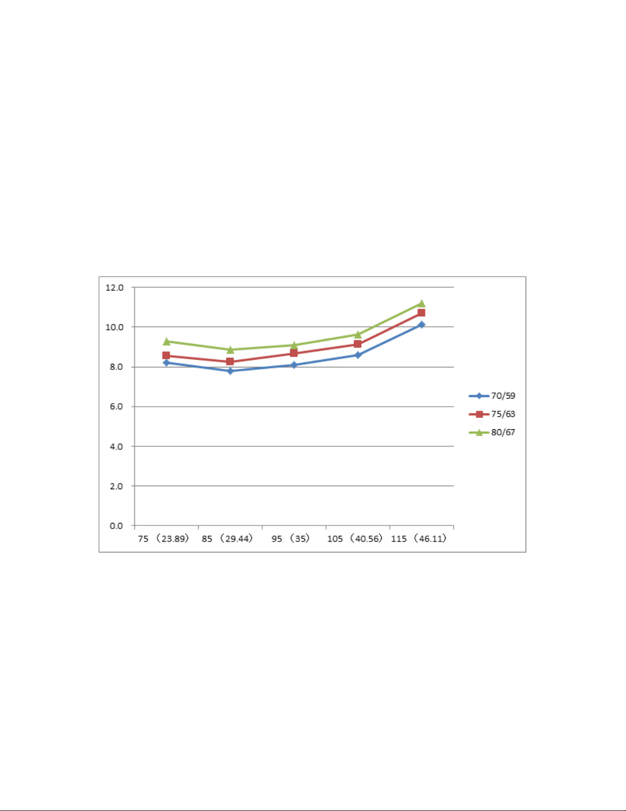
Pressure on Service Port
Table 23—Cooling Chart
°F (°C )
ODT
IDT
75
(23.89)
85
(29.44)
95
(35)
105
(40.56)
115
(46.11)
BAR 70/59 8.2 7.8 8.1 8.6 10.1
BAR 75/63 8.6 8.3 8.7 9.1 10.7
BAR 80/67 9.3 8.9 9.1 9.6 11.2
°F (°C )
ODT
IDT
75
(23.89)
85
(29.44)
95
(35)
105
(40.56)
115
(46.11)
PSI 70/59 119 113 117 125 147
PSI 75/63 124 120 126 132 155
PSI 80/67 135 129 132 140 162
°F (°C )
ODT
IDT
75
(23.89)
85
(29.44)
95
(35)
105
(40.56)
115
(46.11)
MPA 70/59 0.82 0.78 0.81 0.86 1.01
MPA 75/63 0.86 0.83 0.87 0.91 1.07
MPA 80/67 0.93 0.89 0.91 0.96 1.12
Fig. 46 – Cooling Chart
47
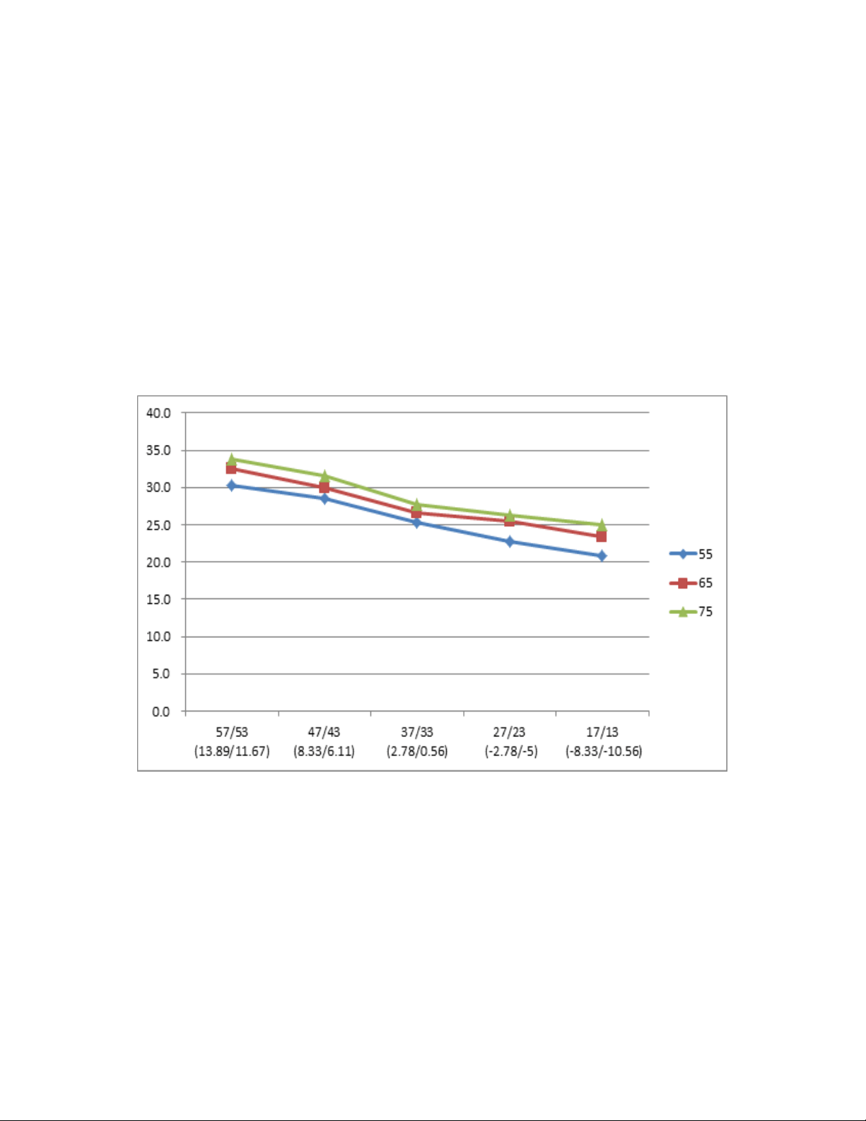
Pressure on Service Port (Cont)
Table 24—Heating Chart
°F (°C )
ODT
IDT
57/53
(13.89/11.67)
47/43
(8.33/6.11)
37/33
(2.78/0.56)
27/23
(-2.78/-5)
17/13
(-8.33/-10.56)
BAR 55 30.3 28.5 25.3 22.8 20.8
BAR 65 32.5 30.0 26.6 25.4 23.3
BAR 75 33.8 31.5 27.8 26.3 24.9
°F (°C )
ODT
IDT
57/53
(13.89/11.67)
47/43
(8.33/6.11)
37/33
(2.78/0.56)
27/23
(-2.78/-5)
17/13
(-8.33/-10.56)
PSI 55 439 413 367 330 302
PSI 65 471 435 386 368 339
PSI 75 489 457 403 381 362
°F (°C )
ODT
IDT
57/53
(13.89/11.67)
47/43
(8.33/6.11)
37/33
(2.78/0.56)
27/23
(-2.78/-5)
17/13
(-8.33/-10.56)
MPA 55 3.03 2.85 2.53 2.28 2.08
MPA 65 3.25 3.00 2.66 2.54 2.33
MPA 75 3.38 3.15 2.78 2.63 2.49
Fig. 47 – Heating Chart
48
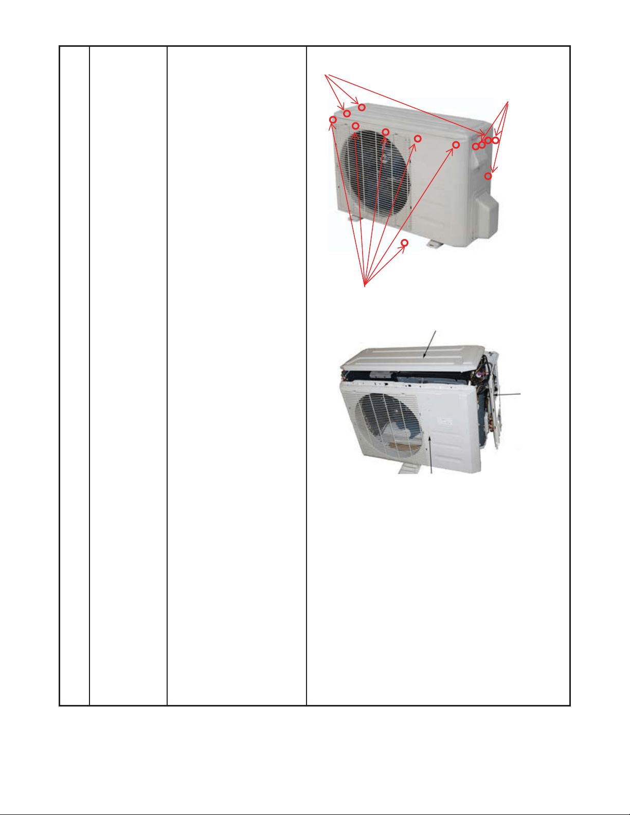
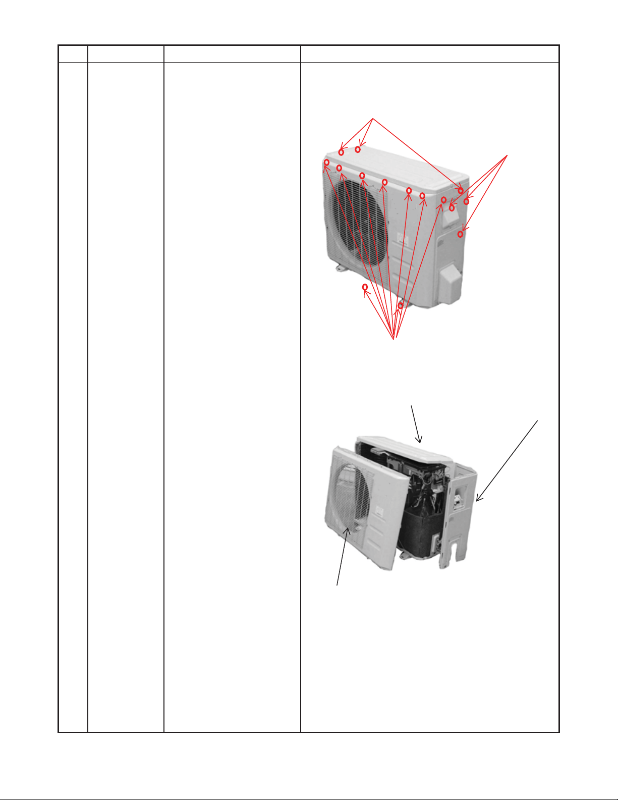
DISASSEMBLY INSTRUCTIONS SIZES 12K (115V)
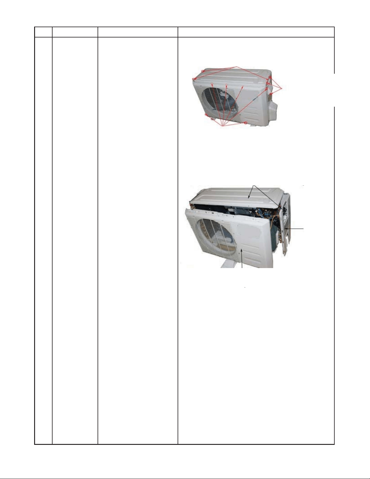
1 Panel plate How to remove the panel
plate.
1. Stop the air conditioner
and turn “OFF” the
power breaker.
2. Remove the big handle
first, and then remove
the top cover (3
screws).
3. Remove the front panel
screws (7).
4. Remove the right side
panel screws (11).
ƻ
2
ƻ
4
ƻ
3
ƻ
3
Front panel screws (7)
Top panel screws (3), 1 screws is under the big handle
Big handle
(3 screws)
49
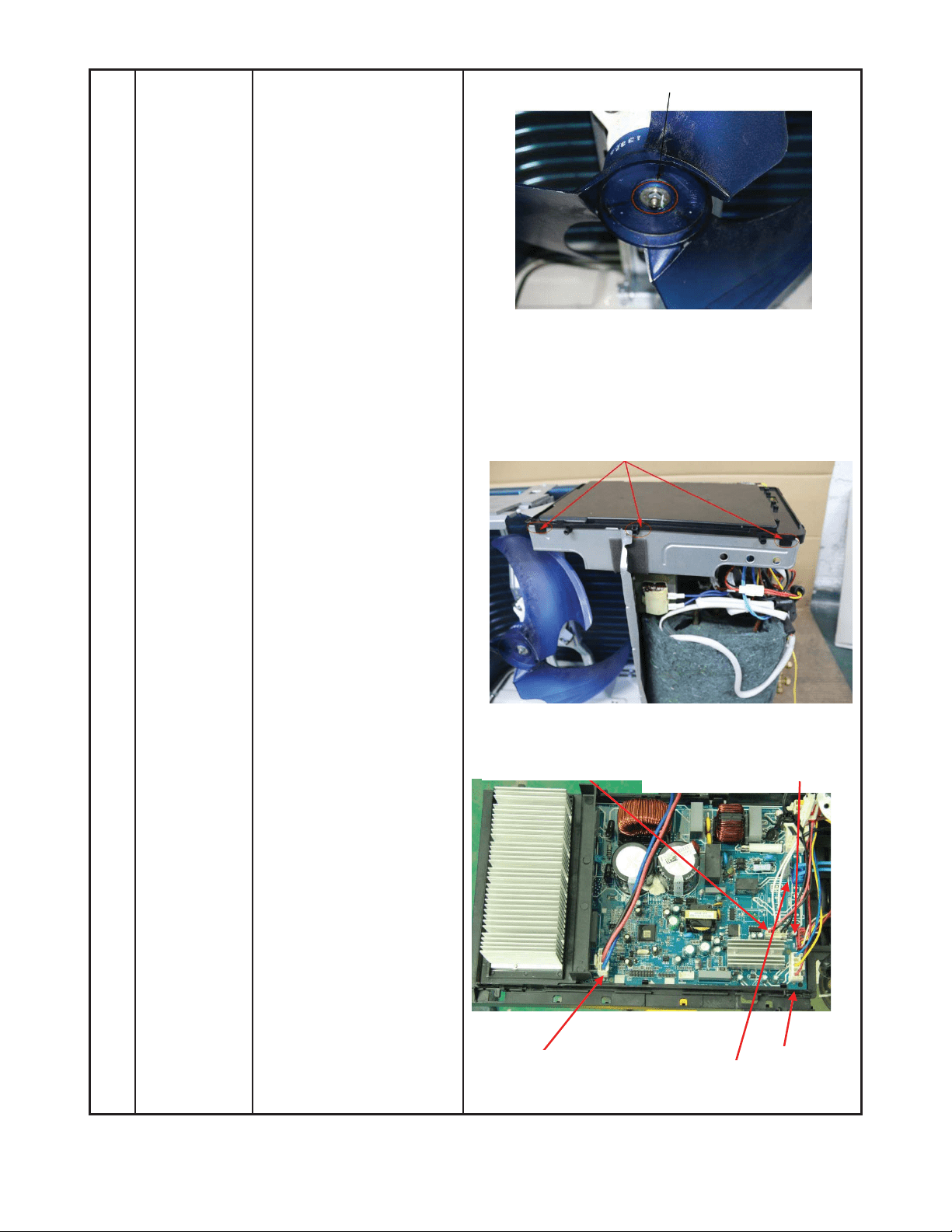
DISASSEMBLY INSTRUCTIONS SIZES 12K (115V) (CONT)
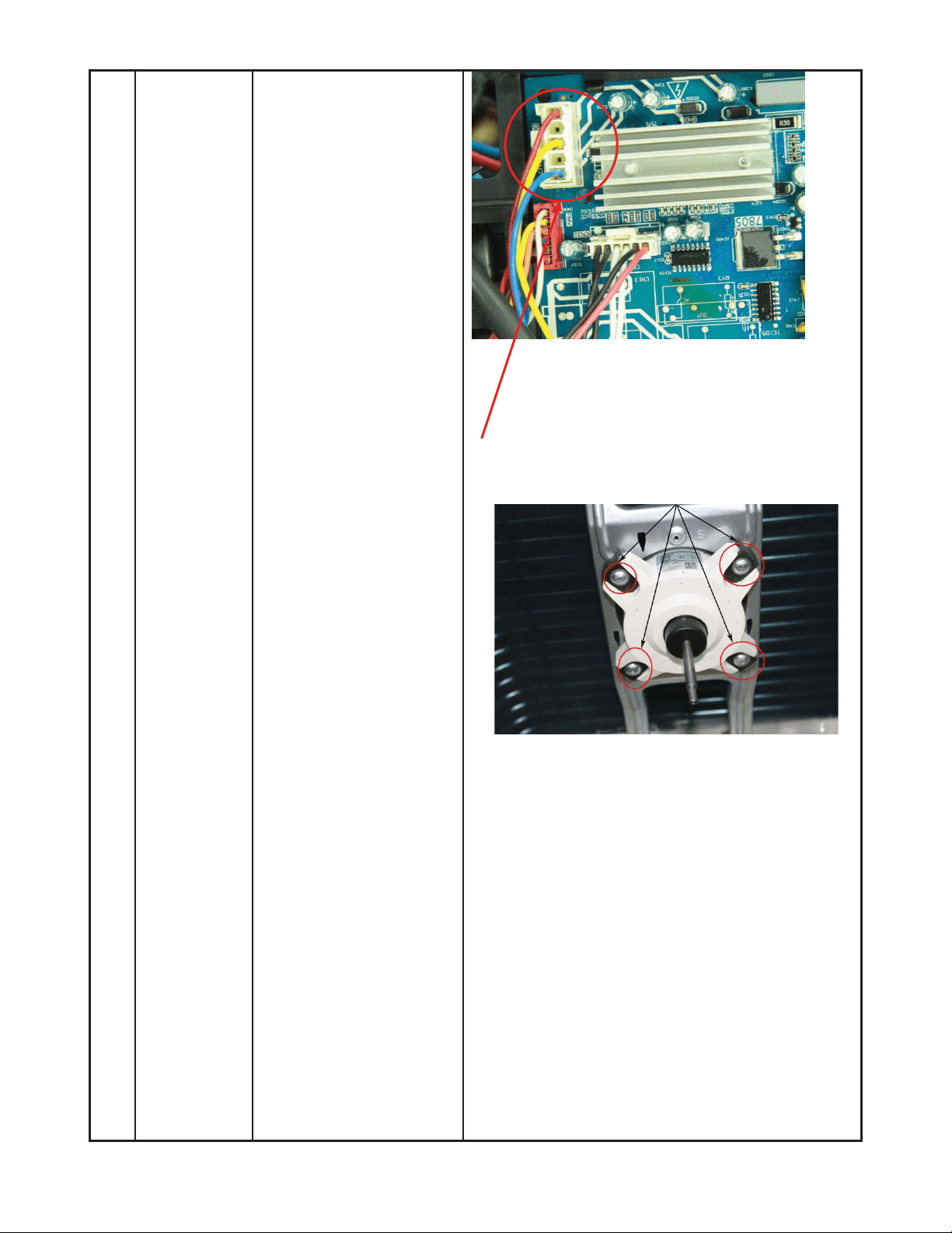
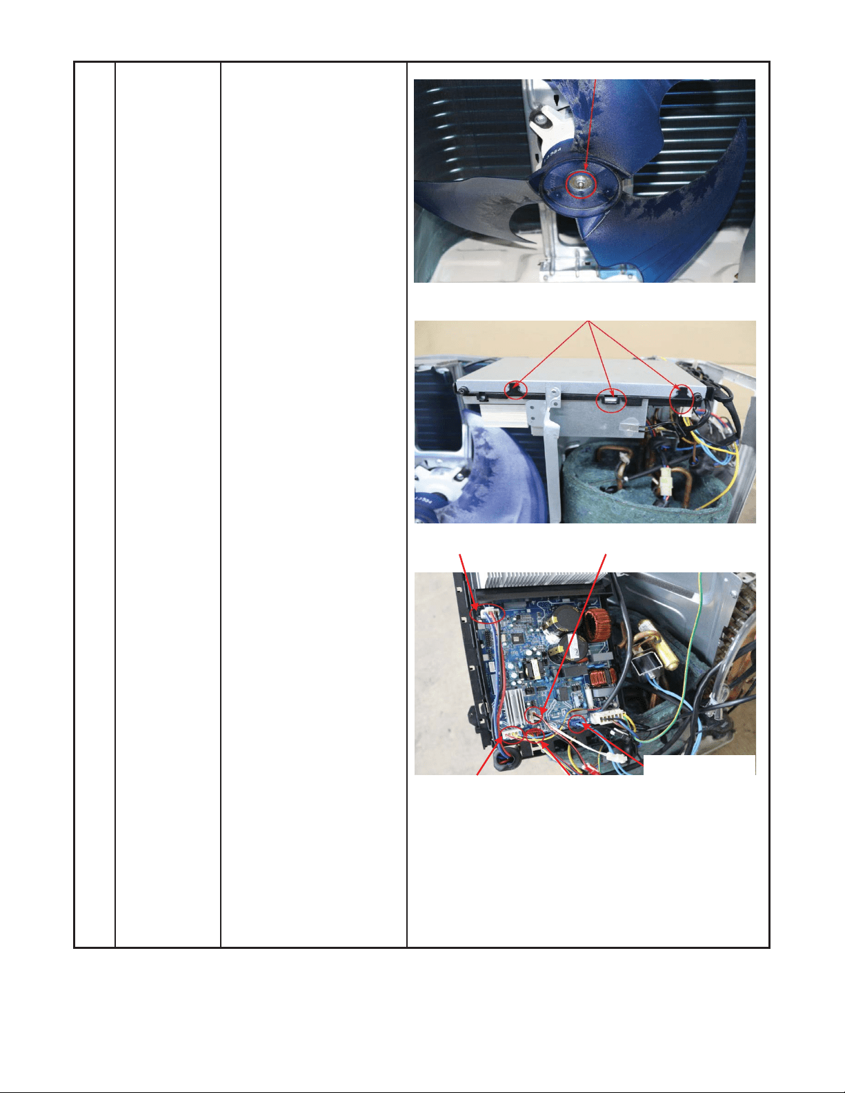
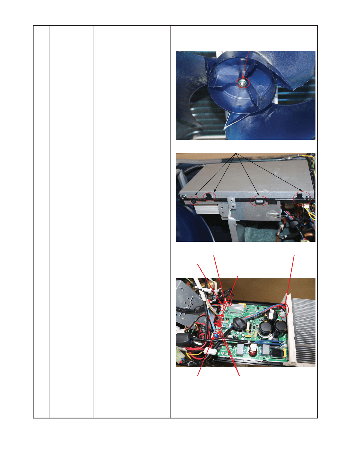
2 Fan
assembly
How to remove the fan
assembly.
1) Remove the nut
securing the fan, and
remove the fan.
2) After removing the top
cover, release the
hooks and open the
electronic control box
cover.
3) Disconnect the fan
motor connector from
the electronic control
board.
ƻ
2
ƻ
3
Compressor
T3, T4, T5 sensor
Motor
Electronic expansion valve
4 wa
y
valve
50
DISASSEMBLY INSTRUCTIONS SIZES 12K (115V) (CONT)
ƻ
5
ĺ
4) Remove the fan motor
screws (4) then remove
the motor.
51
DISASSEMBLY INSTRUCTIONS SIZES 12K (115V) (CONT)
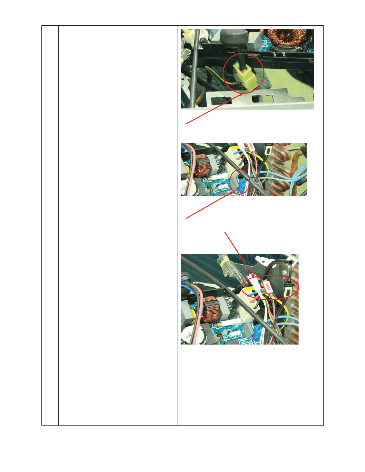
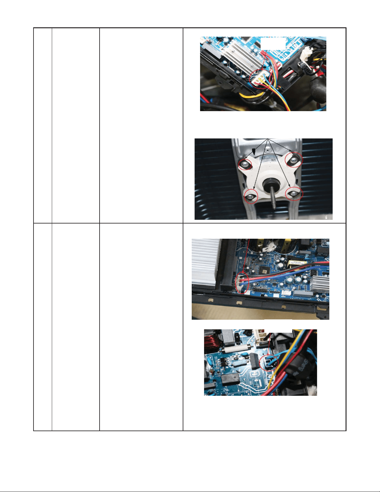
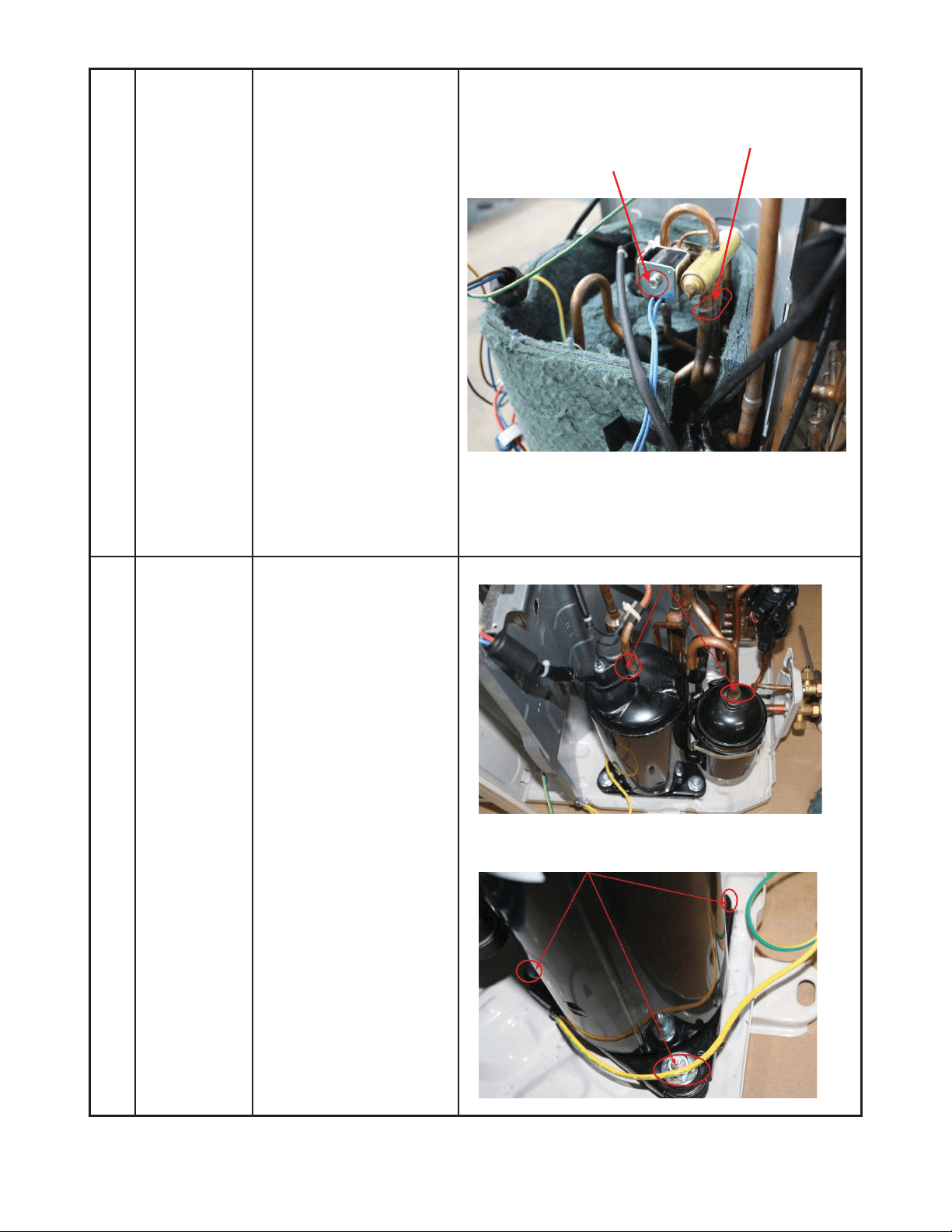
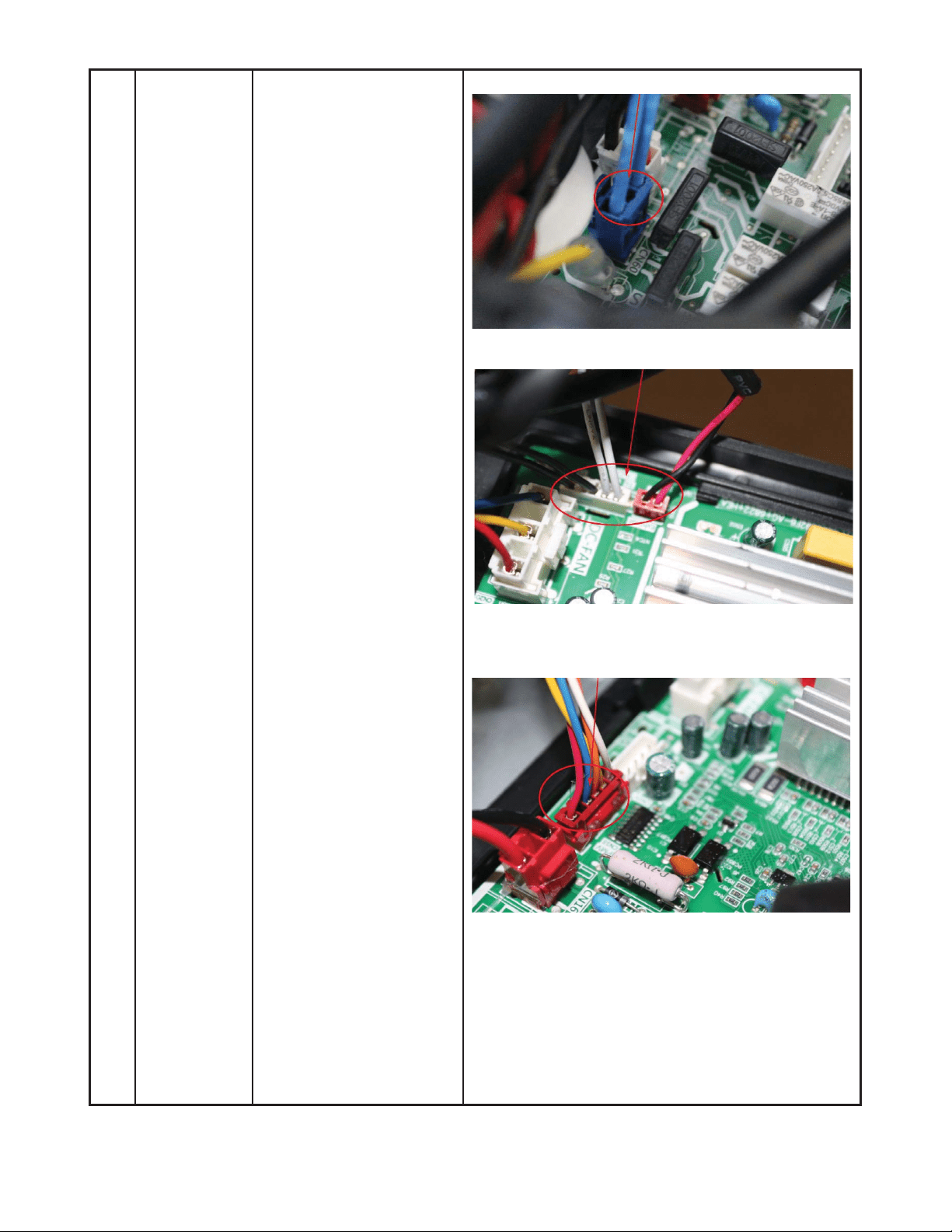
3 Electrical
parts
How to remove the
electrical parts.
1) After you complete the
steps in item 1 and 2,
remove the compressor
connector.
2) Pull out the two blue
wires connected to the
four way valve.
3) Pull out connectors of
the condenser coil
temp. sensor (T3),
outdoor ambient temp.
sensor (T4) and
discharge temp. sensor
(T5).
ƻ
1
ƻ
2
ƻ
3
52
DISASSEMBLY INSTRUCTIONS SIZES 12K (115V) (CONT)
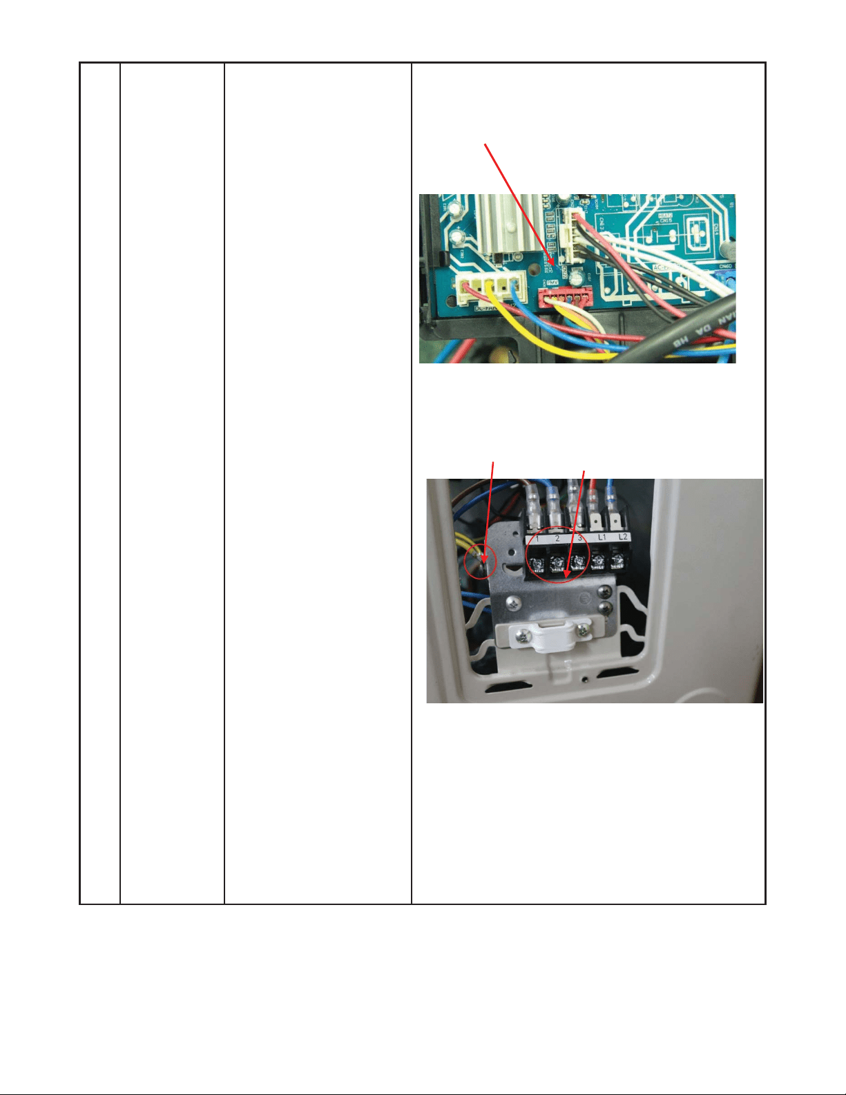
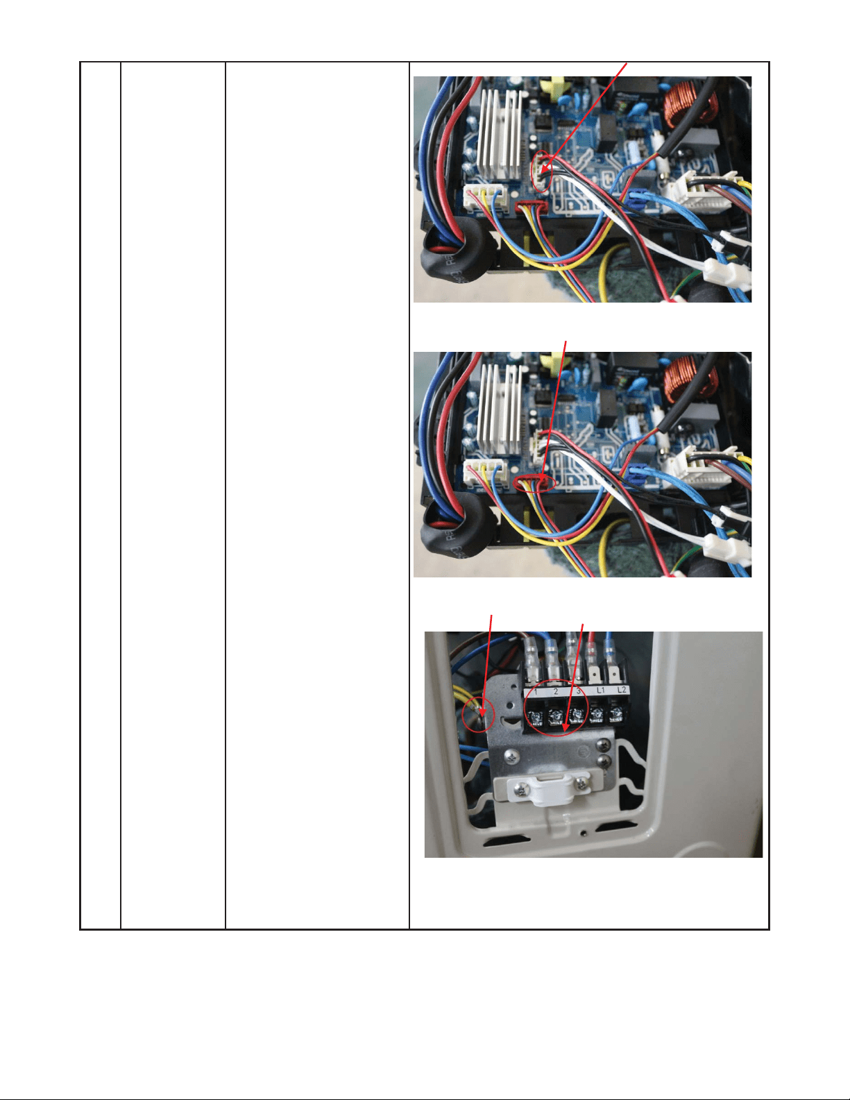
4) Disconnect the
electronic expansion
valve wire from the
control board.
5) Remove the ground
wires.
6) Remove the wires
(1,2,3).
7) Remove the electronic
control box.
ƻ
5
ƻ
6
ĺ
53
DISASSEMBLY INSTRUCTIONS SIZES 12K (115V) (CONT)
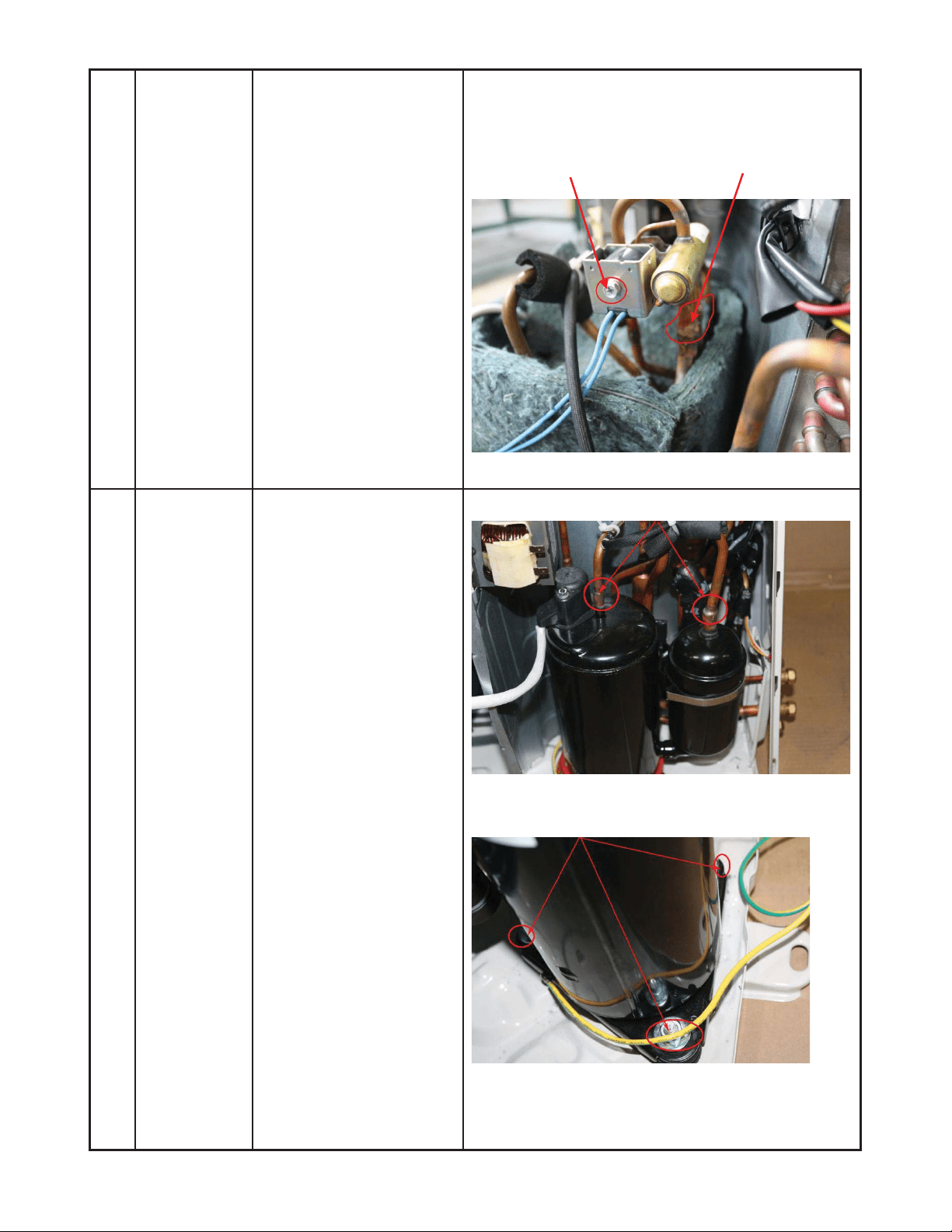
4 Four-way
valve
How to remove the
four-way valve.
1) Perform the work of
sections 1 and 3.
2) Recover refrigerant
from the refrigerant
circuit.
3) Remove the coil screw
then remove the coil.
4) Detach the welded
parts of the four-way
valve and pipe.
5) Remove the four-way
valve assembly.
The picture of four-way valve may be different from
your actual valve.
5 Compressor How to remove the
compressor.
1) Complete the work of
sections1 and 3.
Recover the refrigerant
from the refrigerant
circuit.
2) Remove the discharge
and suction pipes with
a burner.
3) Remove the hex nuts
and washers securing
the compressor on the
bottom plate.
4) Lift the compressor
from the base pan
assembly.
ƻ
2
ƻ
3
ĺ
ƻ
3
54
DISASSEMBLY INSTRUCTIONS SIZES 12K (208−230V)
No. Part name Procedures Remarks
Panel plate How to remove the panel
plate.
1) Stop the air conditioner
and turn “OFF” the
power breaker.
2) Remove the big handle
first, then remove the
top panel (3 screws).
3) Remove the front
panel screws (6).
4) Remove the right side
panel screws (8).
ƻ
2
ƻ
4
ƻ
3
Top panel screws (3 screws, 1 screw is under the big handle)
Big
Handler screws (3)
Front panel screws (6)
1
55
DISASSEMBLY INSTRUCTIONS SIZES 12K (208−230V) (CONT)
2 Fan
assembly
How to remove the fan
assembly.
1) After removing the
panel plate using
section 1, remove the
hex nut securing the
fan then remove the
fan.
2) Release the hooks
and open the
electronic control box
cover.
ƻ
1
ƻ
2
Compressor
T3, T4, T5 sensor
Motor
Electronic expansion valve
4 way valve
56
DISASSEMBLY INSTRUCTIONS SIZES 12K (208−230V) (CONT)
3) Disconnect the fan
motor connector and
from the electronic
control board.
4) Remove the fan motor
screws (4). Then
remove the fan motor.
3 Electrical
parts
How to remove the
electrical parts.
1) After completing the
work in sections 1 and
2, remove the
compressor
connectors.
2) Pull out the two blue
wires connected with
the four way valve.
ƻ
1
ƻ
3
ƻ
3
ƻ
4
ƻ
2
57
DISASSEMBLY INSTRUCTIONS SIZES 12K (208−230V) (CONT)
3) Pull out connectors of
the condenser coil
temp. sensor
(T3),outdoor ambient
temp. sensor (T4) and
discharge temp.
sensor (T5).
4) Disconnect the
electronic expansion
valve wire.
5) Remove the
grounding screw.
6) Remove the wires (1,
2, 3). Then remove
the electronic control
box.
ƻ
4
ƻ
5
ƻ
6
58
DISASSEMBLY INSTRUCTIONS SIZES 12K (208−230V) (CONT)
4 Four-way
valve
How to remove the
four-way valve.
1) Complete the steps in
sections 1, 3.
2) Recover refrigerant
from the refrigerant
circuit.
3) Remove the coil
screw then remove
the coil.
4) Detach the welded
parts of the four-way
valve and pipe.
5) Remove the four-way
valve assembly.
The picture of four-way valve may differ from your
actual valve.
ƻ
3
ƻ
4
5 Compressor How to remove the
compressor.
1) Complete steps in
sections 1, 3.
2) Recover refrigerant
from the refrigerant
circuit.
3) Remove the
4) discharge and suction
pipes with a burner.
5) Remove the hex nuts
and washers securing
the compressor on
the bottom plate.
6) Lift the compressor
from the base pan
assembly.
ƻ
2
ƻ
3
59
DISASSEMBLY INSTRUCTIONS SIZES 18K (208−230V)
No. Part name Procedures Remarks
Panel plate How to remove the panel
plate.
1) Stop the air
conditioner and turn
ĀOFFāthe power
breaker.
2) Remove the top panel
screws (3).
3) Remove the front
panel screws (9).
4) Remove the right side
panel screws (8).
ƻ
2
ƻ
4
ƻ
3
Toppanelscrews (3)
Front panel screws (9)
Big handle
screws (3)
1
60
DISASSEMBLY INSTRUCTIONS SIZES 18K (208−230V) (CONT)
2 Fan
assembly
How to remove the fan
assembly.
1) After removing the
panel plate using
section 1, remove the
hex nut securing the
fan then remove the
fan.
2) After removing the top
cover, release the
hooks then open the
electronic control box
cover.
ƻ
1
ƻ
2
T3
,
T4
,
T5 sensor
Motor wire Electronic
expansion valve
Compressor wire
4 way valve wire
Electric pipe heater and Crankcase
electric heater
61
DISASSEMBLY INSTRUCTIONS SIZES 18K (208−230V) (CONT)
3) Disconnect the
connector for fan
motor from the
electronic control
board.
4) Remove the fan motor
screws. Then remove
the fan motor.
3 Electrical
parts
How to remove the
electrical parts.
1) Complete the work of
items 1 and 2, then
remove the
compressor and
reactor connectors.
ƻ
1
ƻ
3
ƻ
4
62
DISASSEMBLY INSTRUCTIONS SIZES 18K (208−230V) (CONT)
2) Pull out the two blue
wires connected to the
four way valve.
3) Remove the
connectors of the
condenser coil temp.
sensor (T3),outdoor
ambient temp. sensor
(T4) and discharge
temp. sensor (T5).
4) Disconnect the
electronic expansion
valve wire.
ƻ
3
ƻ
3
ƻ
4
ƻ
2
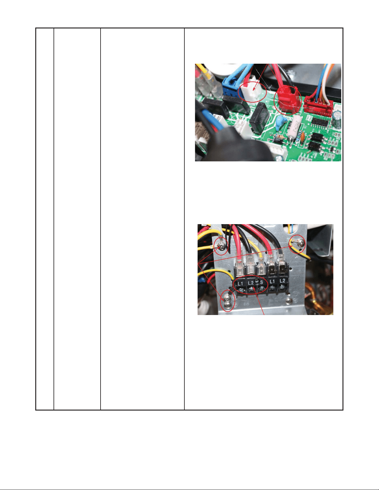
63
DISASSEMBLY INSTRUCTIONS SIZES 18K (208−230V) (CONT)
5) Remove the electric
heaters.
6) Remove the grounding
screw.
7) Remove the wires (1,
2, 3 or L1, L2, S). Then
remove the electronic
control box.
ƻ
5
ƻ
7
ļ
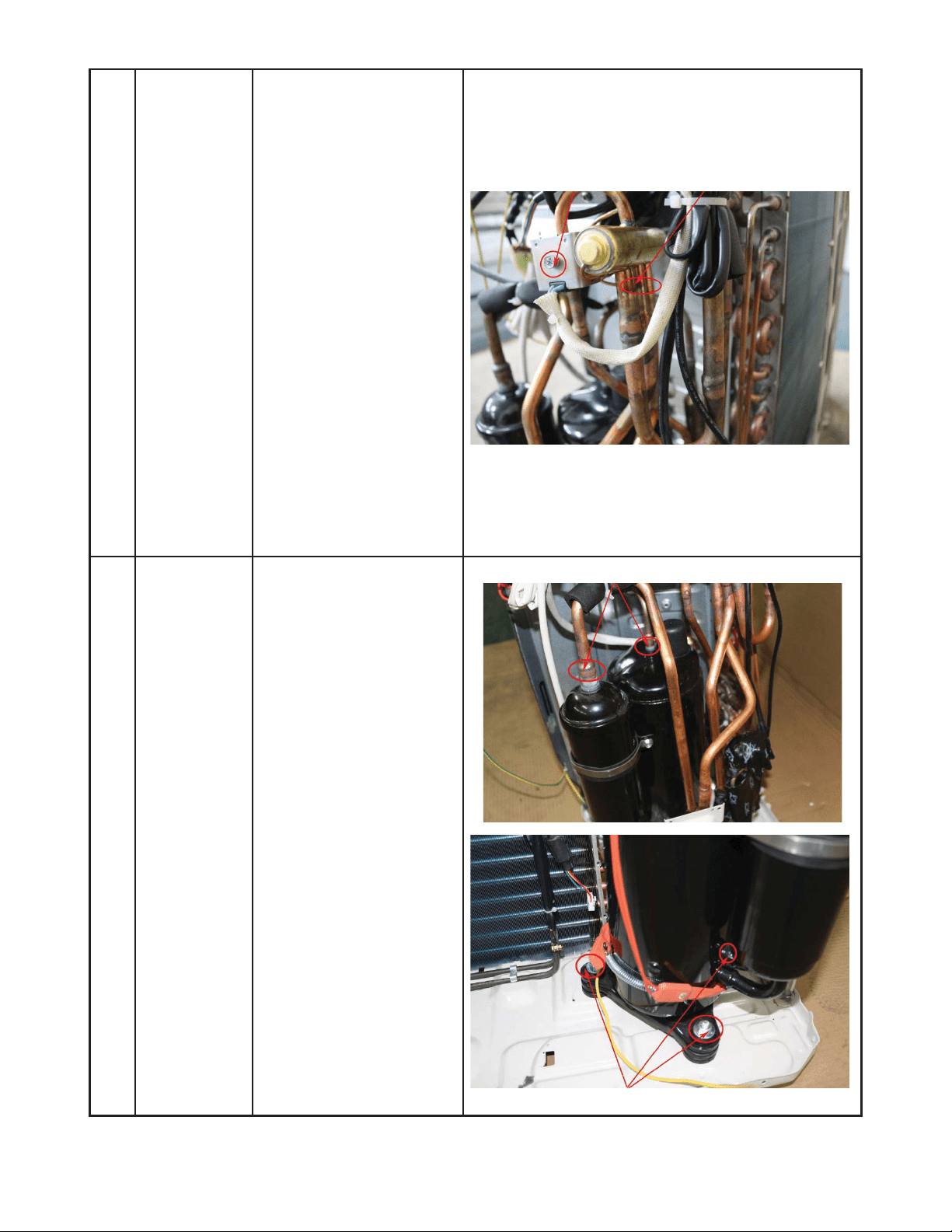
64
DISASSEMBLY INSTRUCTIONS SIZES 18K (208−230V) (CONT)
4 Four-way
valve
How to remove the
four-way valve.
1) Complete the steps in
sections 1, 3.
2) Recover refrigerant
from the refrigerant
circuit.
3) Remove the coil screw
then remove the coil.
4) Detach the welded
parts of four-way valve
and pipe.
5) Remove the four-way
valve assembly.
The picture of four-way valve may differ from your
actual valve.
ƻ
3
5 Compressor How to remove the
compressor.
1) After completing steps
in sections 1, 3,
recover refrigerant
from the refrigerant
circuit.
2) Remove the discharge
and suction pipes with
a burner.
3) Remove the hex nuts
and washers securing
the compressor on the
bottom plate.
5) Lift the compressor
from the base pan
assembly.
ƻ
2
ƻ
3
ĺ
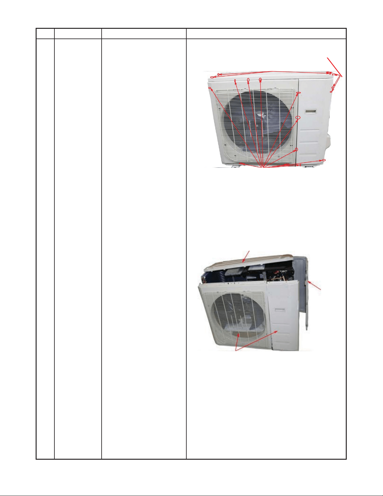
65
DISASSEMBLY INSTRUCTIONS SIZES 24K (208−230V)
No. Part name Procedures Remarks
1 Panel plate How to remove the panel
plate.
1) Stop the air
conditioner and turn
“OFF” the power
breaker.
2) Remove the big
handle first, then
remove the top cover
(7 screws).
3) Remove the front
panel screws (11).
4) Remove the right side
panel screws (13).
ƻ
2
ƻ
4
ƻ
3
Front panel screws (11)
Top panel screws (3), 1 screw is under the big handle)
Big handle screws (4)
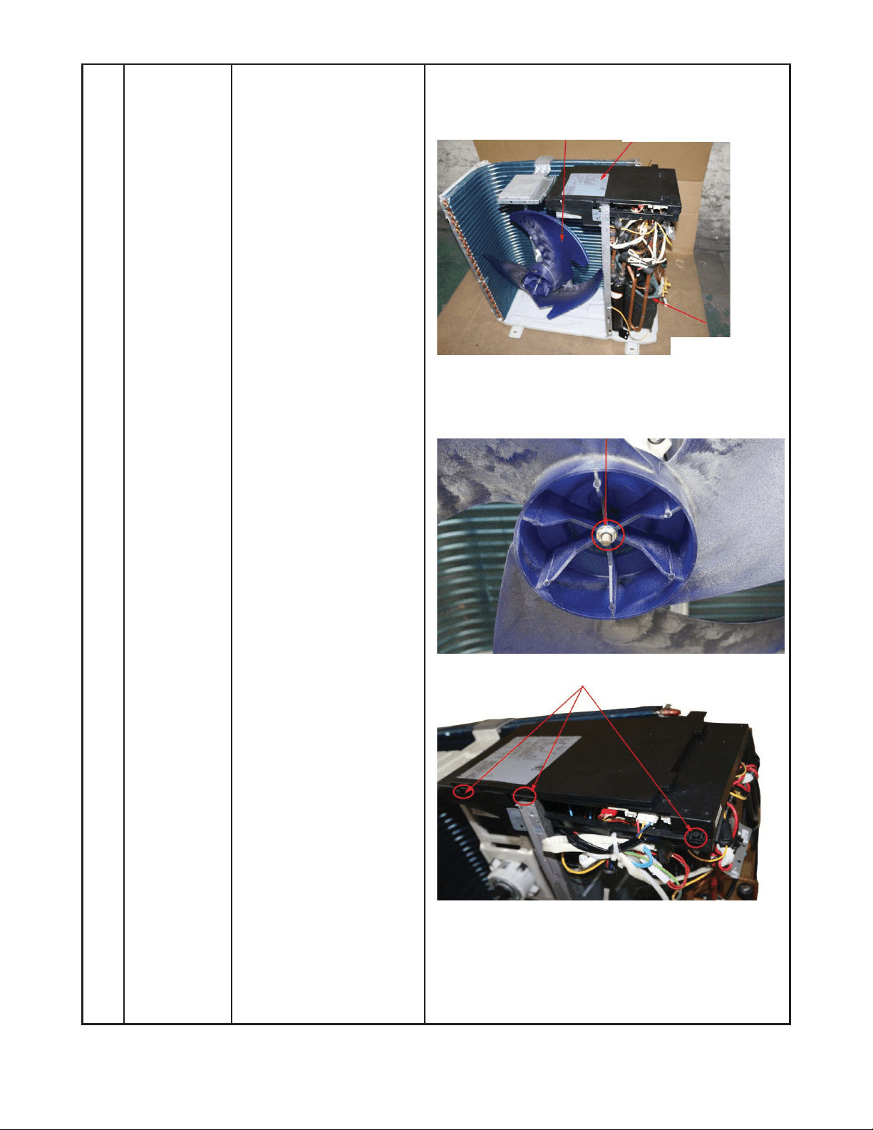
66
DISASSEMBLY INSTRUCTIONS SIZES 24K (208−230V) (CONT)
2 Fan
assembly
How to remove the fan
assembly.
1) Remove the panel
plate using the steps in
section 1.
2) Remove the nut
securing the fan, then
remove the fan.
3) Release the hooks and
remove the screws.
Open the electronic
control box cover.
ƻ
2
ƻ
3
Fan
Electronic control box
Compressor
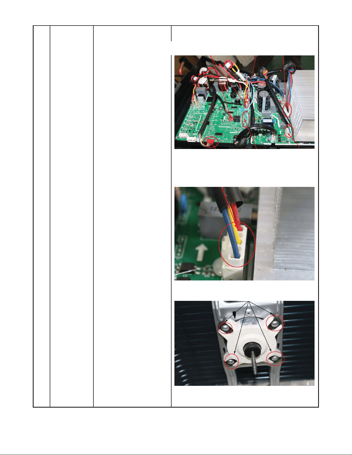
67
DISASSEMBLY INSTRUCTIONS SIZES 24K (208−230V) (CONT)
4) Disconnect the fan
motor connector from
the electronic control
board.
5) Remove the fan motor
screws (4) of the fan
motor, then remove
the motor.
ƻ
5
ƻ
4
T3, T4, T5, sensor
Pressure switch
Compressor
wire
Electronic expansion
4 wa
y
valve
Motor wire
ƻ
5
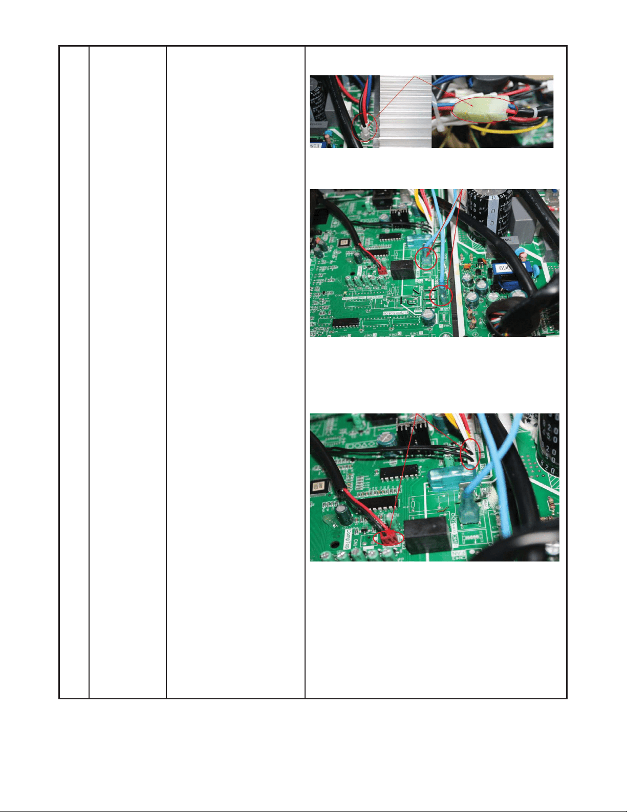
68
DISASSEMBLY INSTRUCTIONS SIZES 24K (208−230V) (CONT)
3 Electrical
parts
How to remove the
electrical parts.
1) After completing the
work in sections 1 and
2, remove the
compressor connector.
2) Pull out the two blue
3) wires connected with
the four way valve.
4) Pull out connectors of
the condenser coil
temp. sensor (T3),
outdoor ambient temp.
sensor (T4) and
discharge temp.
sensor (T5).
ƻ
1
ƻ
2
ƻ
3
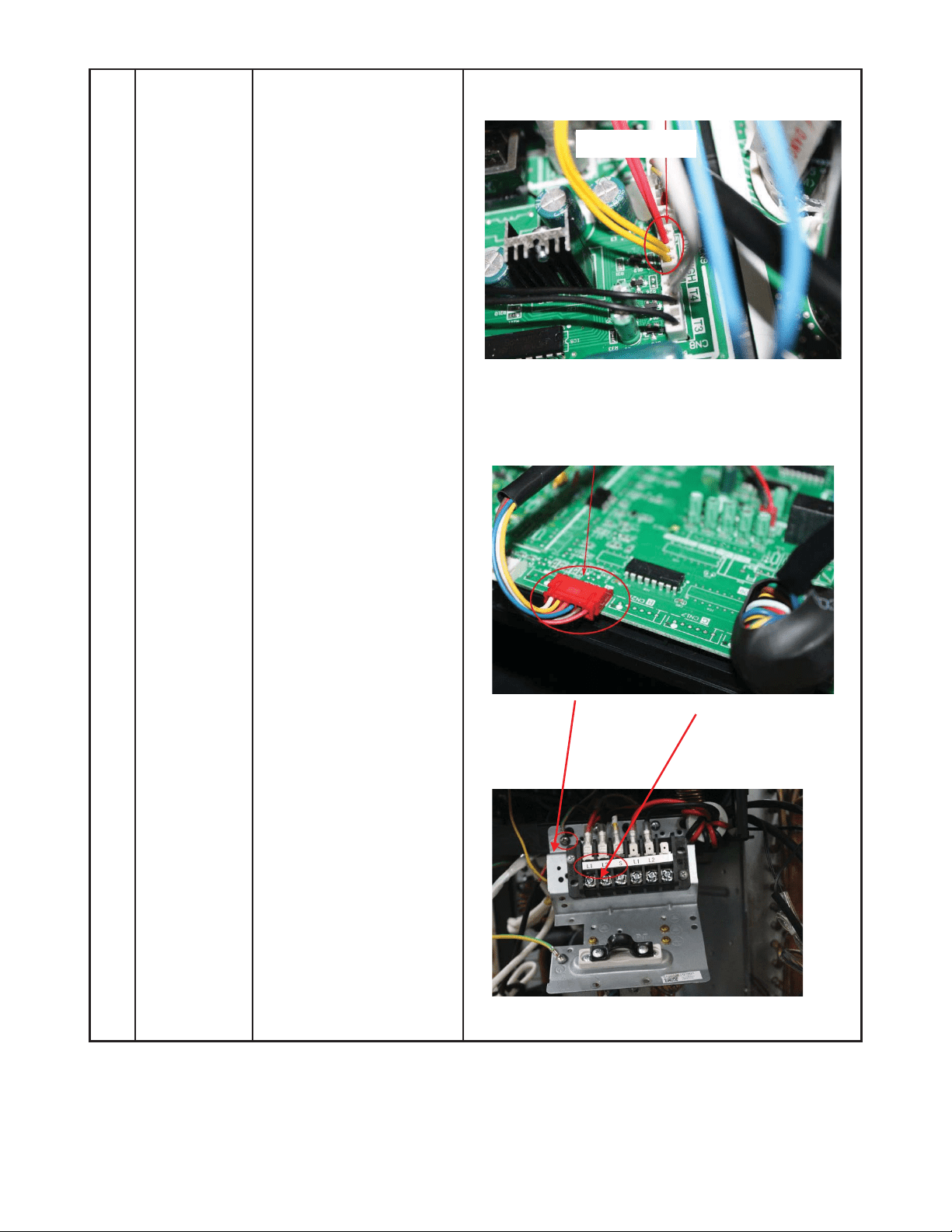
69
DISASSEMBLY INSTRUCTIONS SIZES 24K (208−230V) (CONT)
5) Disconnect the
pressure switch
connector.
6) Disconnect the
electronic expansion
valve wire from the
control board.
7) Remove the ground
wires.
8) Remove the wires (1,
2, 3 or L1, L2, S). Then
remove the electronic
control box.
ƻ
6
ƻ
7
ƻ
5
ƻ
4
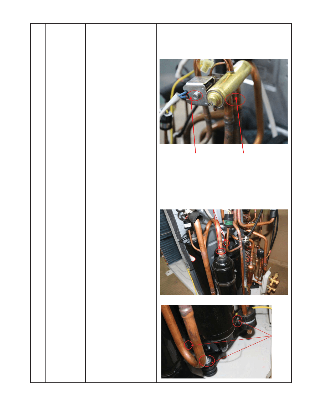
70
DISASSEMBLY INSTRUCTIONS SIZES 24K (208−230V) (CONT)
4 Four-way
valve
How to remove the
four-way valve.
1) Complete the steps in
sections 1, 3.
2) Recover the refrigerant
from the refrigerant
circuit.
3) Remove the coil screw
and then remove the
coil.
4) Detach the welded
parts of four-way valve
and pipe.
5) Remove the four-way
valve assembly.
The picture of four-way valve may differ from your
actual valve.
5 Compressor How to remove the
compressor.
1) Complete steps in
sections 1, 3. Recover
refrigerant from the
refrigerant circuit.
2) Remove the discharge
and suction pipes with
a burner.
3) Remove the hex nuts
and washers securing
the compressor to the
bottom plate.
4) Lift the compressor
from the base pan
assembly.
ƻ
2
Ĺ
ƻ
3
ƻ
4

71
APPENDIX
Appendix 1
Table 25—Temperature Sensor Resistance Value Table for T1, T2, T3, T4
°C
°F K Ohm °C °F K Ohm °C °F K Ohm °C °F K Ohm
-20 -4 115.266 20 68 12.6431 60 140 2.35774 100 212 0.62973
-19 -2 108.146 21 70 12.0561 61 142 2.27249 101 214 0.61148
-18 0 101.517 22 72 11.5 62 144 2.19073 102 216 0.59386
-17 1 96.3423 23 73 10.9731 63 145 2.11241 103 217 0.57683
-16 3 89.5865 24 75 10.4736 64 147 2.03732 104 219 0.56038
-15 5 84.219 25 77 10 65 149 1.96532 105 221 0.54448
-14 7 79.311 26 79 9.55074 66 151 1.89627 106 223 0.52912
-13 9 74.536 27 81 9.12445 67 153 1.83003 107 225 0.51426
-12 10 70.1698 28 82 8.71983 68 154 1.76647 108 226 0.49989
-11 12 66.0898 29 84 8.33566 69 156 1.70547 109 228 0.486
-10 14 62.2756 30 86 7.97078 70 158 1.64691 110 230 0.47256
-9 16 58.7079 31 88 7.62411 71 160 1.59068 111 232 0.45957
-8 18 56.3694 32 90 7.29464 72 162 1.53668 112 234 0.44699
-7 19 52.2438 33 91 6.98142 73 163 1.48481 113 235 0.43482
-6 21 49.3161 34 93 6.68355 74 165 1.43498 114 237 0.42304
-5 23 46.5725 35 95 6.40021 75 167 1.38703 115 239 0.41164
-4 25 44 36 97 6.13059 76 169 1.34105 116 241 0.4006
-3 27 41.5878 37 99 5.87359 77 171 1.29078 117 243 0.38991
-2 28 39.8239 38 100 5.62961 78 172 1.25423 118 244 0.37956
-1 30 37.1988 39 102 5.39689 79 174 1.2133 119 246 0.36954
0 32 35.2024 40 104 5.17519 80 176 1.17393 120 248 0.35982
1 34 33.3269 41 106 4.96392 81 178 1.13604 121 250 0.35042
2 36 31.5635 42 108 4.76253 82 180 1.09958 122 252 0.3413
3 37 29.9058 43 109 4.5705 83 181 1.06448 123 253 0.33246
4 39 28.3459 44 111 4.38736 84 183 1.03069 124 255 0.3239
5 41 26.8778 45 113 4.21263 85 185 0.99815 125 257 0.31559
6 43 25.4954 46 115 4.04589 86 187 0.96681 126 259 0.30754
7 45 24.1932 47 117 3.88673 87 189 0.93662 127 261 0.29974
8 46 22.5662 48 118 3.73476 88 190 0.90753 128 262 0.29216
9 48 21.8094 49 120 3.58962 89 192 0.8795 129 264 0.28482
10 50 20.7184 50 122 3.45097 90 194 0.85248 130 266 0.2777
11 52 19.6891 51 124 3.31847 91 196 0.82643 131 268 0.27078
12 54 18.7177 52 126 3.19183 92 198 0.80132 132 270 0.26408
13 55 17.8005 53 127 3.07075 93 199 0.77709 133 271 0.25757
14 57 16.9341 54 129 2.95896 94 201 0.75373 134 273 0.25125
15 59 16.1156 55 131 2.84421 95 203 0.73119 135 275 0.24512
16 61 15.3418 56 133 2.73823 96 205 0.70944 136 277 0.23916
17 63 14.6181 57 135 2.63682 97 207 0.68844 137 279 0.23338
18 64 13.918 58 136 2.53973 98 208 0.66818 138 280 0.22776
19 66 13.2631 59 138 2.44677 99 210 0.64862 139 282 0.22231

72
Appendix 2
Table 26—Temperature Sensor Resistance Value Table for T5
°C
°F K Ohm °C °F K Ohm °C °F K Ohm °C °F K Ohm
-20 -4 542.7 20 68 68.66 60 140 13.59 100 212 3.702
-19 -2 511.9 21 70 65.62 61 142 13.11 101 214 3.595
-18 0 483 22 72 62.73 62 144 12.65 102 216 3.492
-17 1 455.9 23 73 59.98 63 145 12.21 103 217 3.392
-16 3 430.5 24 75 57.37 64 147 11.79 104 219 3.296
-15 5 406.7 25 77 54.89 65 149 11.38 105 221 3.203
-14 7 384.3 26 79 52.53 66 151 10.99 106 223 3.113
-13 9 363.3 27 81 50.28 67 153 10.61 107 225 3.025
-12 10 343.6 28 82 48.14 68 154 10.25 108 226 2.941
-11 12 325.1 29 84 46.11 69 156 9.902 109 228 2.86
-10 14 307.7 30 86 44.17 70 158 9.569 110 230 2.781
-9 16 291.3 31 88 42.33 71 160 9.248 111 232 2.704
-8 18 275.9 32 90 40.57 72 162 8.94 112 234 2.63
-7 19 261.4 33 91 38.89 73 163 8.643 113 235 2.559
-6 21 247.8 34 93 37.3 74 165 8.358 114 237 2.489
-5 23 234.9 35 95 35.78 75 167 8.084 115 239 2.422
-4 25 222.8 36 97 34.32 76 169 7.82 116 241 2.357
-3 27 211.4 37 99 32.94 77 171 7.566 117 243 2.294
-2 28 200.7 38 100 31.62 78 172 7.321 118 244 2.233
-1 30 190.5 39 102 30.36 79 174 7.086 119 246 2.174
0 32 180.9 40 104 29.15 80 176 6.859 120 248 2.117
1 34 171.9 41 106 28 81 178 6.641 121 250 2.061
2 36 163.3 42 108 26.9 82 180 6.43 122 252 2.007
3 37 155.2 43 109 25.86 83 181 6.228 123 253 1.955
4 39 147.6 44 111 24.85 84 183 6.033 124 255 1.905
5 41 140.4 45 113 23.89 85 185 5.844 125 257 1.856
6 43 133.5 46 115 22.89 86 187 5.663 126 259 1.808
7 45 127.1 47 117 22.1 87 189 5.488 127 261 1.762
8 46 121 48 118 21.26 88 190 5.32 128 262 1.717
9 48 115.2 49 120 20.46 89 192 5.157 129 264 1.674
10 50 109.8 50 122 19.69 90 194 5 130 266 1.632
11 52 104.6 51 124 18.96 91 196 4.849
12 54 99.69 52 126 18.26 92 198 4.703
13 55 95.05 53 127 17.58 93 199 4.562
14 57 90.66 54 129 16.94 94 201 4.426
15 59 86.49 55 131 16.32 95 203 4.294
16 61 82.54 56 133 15.73 96 205 4.167
17 63 78.79 57 135 15.16 97 207 4.045
18 64 75.24 58 136 14.62 98 208 3.927
19 66 71.86 59 138 14.09 99 210 3.812

73
Appendix 3
Table 27—Celsius to Fahrenheit
°C °F °C °F °C °F °C °F °C °F
-5 23 21 69.8 51 123.8 82 179.6 113 235.4
-4 24.8 22 71.6 52 125.6 83 181.4 114 237.2
-3 26.6 23 73.4 53 127.4 84 183.2 115 239
-2 28.4 24 75.2 54 129.2 85 185 116 240.8
-1 30.2 25 77 55 131 86 186.8 117 242.6
0 32 25.5 77.9 56 132.8 87 188.6 118 244.4
0.5 32.9 26 78.8 57 134.6 88 190.4 119 246.2
1 33.8 27 80.6 58 136.4 89 192.2 120 248
1.5 34.7 28 82.4 59 138.2 90 194 121 249.8
2 35.6 29 84.2 60 140 91 195.8 122 251.6
2.5 36.5 30 86 61 141.8 92 197.6 123 253.4
3 37.4 31 87.8 62 143.6 93 199.4 124 255.2
3.5 38.3 32 89.6 63 145.4 94 201.2 125 257
4 39.2 33 91.4 64 147.2 95 203 126 258.8
4.5 40.1 34 93.2 65 149 96 204.8 127 260.6
5 41 35 95 66 150.8 97 206.6 128 262.4
6 42.8 36 96.8 67 152.6 98 208.4 129 264.2
7 44.6 37 98.6 68 154.4 99 210.2 130 266
8 46.4 38 100.4 69 156.2 100 212 131 267.8
9 48.2 39 102.2 70 158 101 213.8 132 269.6
10 50 40 104 71 159.8 102 215.6 133 271.4
11 51.8 41 105.8 72 161.6 103 217.4 134 273.2
12 53.6 42 107.6 73 163.4 104 219.2 135 275
13 55.4 43 109.4 74 165.2 105 221 136 276.8
14 57.2 44 111.2 75 167 106 222.8 137 278.6
15 59 45 113 76 168.8 107 224.6 138 280.4
16 60.8 46 114.8 77 170.6 108 226.4 139 282.2
17 62.6 47 116.6 78 172.4 109 228.2 140 284
18 64.4 48 118.4 79 174.2 110 230 141 285.8
19 66.2 49 120.2 80 176 111 231.8 142 287.6
20 68 50 122 81 177.8 112 233.6 143 289.4

74
Copyright 2018 CAC/BDP. S 7310 W. Morris St. S Indianapolis, IN 46231
Manufacturer reserves the right to change, at any time, specifications and designs without notice and without obligations.
Catalog No. SG-38MHRB-01
Replaces: NEW
Edition Date: 08/18