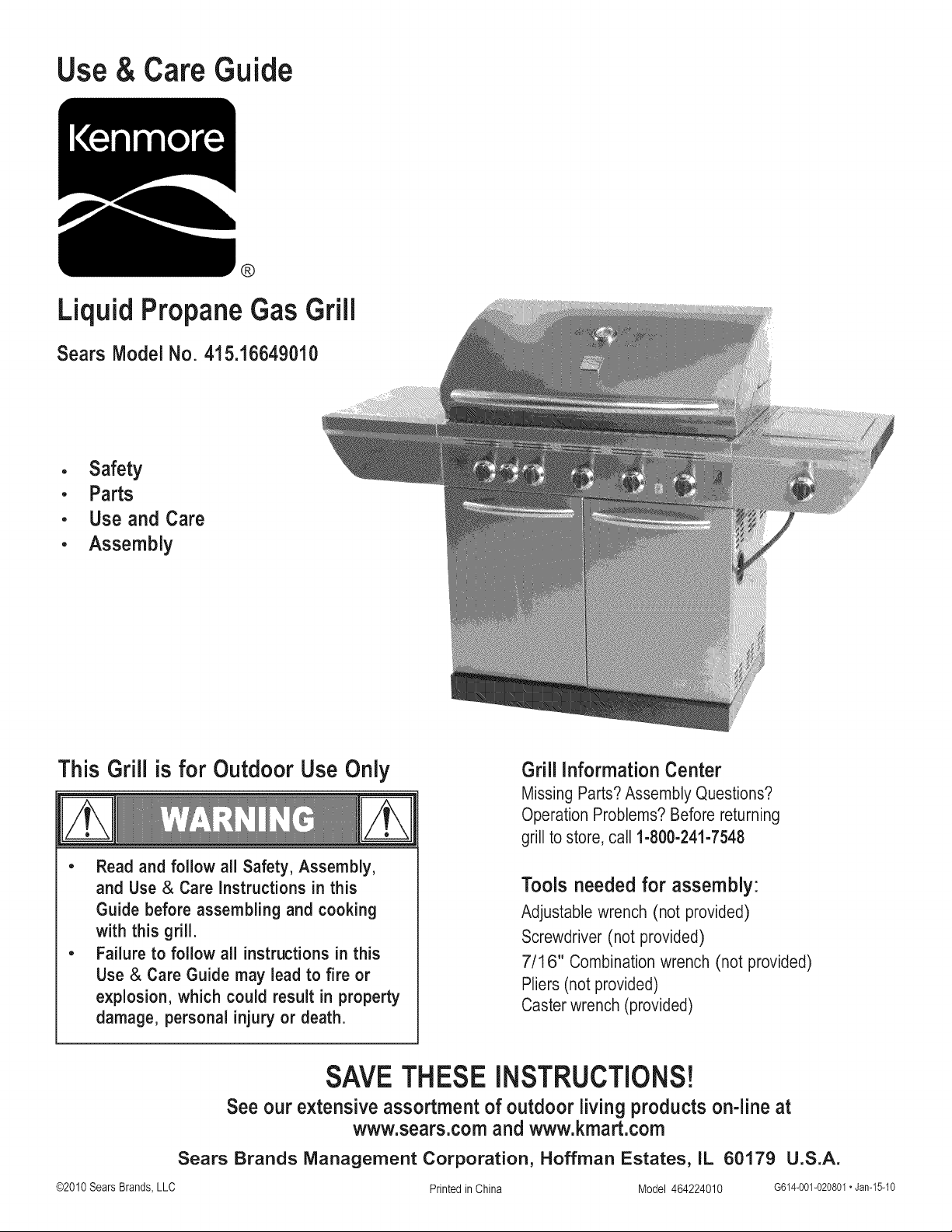
Use& Care Guide
• Safety
• Parts
• Use and Care
• Assembly
This Grill is for Outdoor Use Only
• Read and follow all Safety, Assembly,
and Use & Care instructions in this
Guide before assembling and cooking
with this grill.
• Failure to follow all instructions in this
Use & Care Guide may lead to fire or
explosion, which could result in property
damage, personal injury or death.
Grill InformationCenter
Missing Parts? Assembly Questions?
Operation Problems? Before returning
grill to store, call 1-800-241-7548
Tools needed for assembly:
Adjustable wrench (not provided)
Screwdriver (not provided)
7/16" Combination wrench (not provided)
Pliers (not provided)
Caster wrench (provided)
SAVETHESEiNSTRUCTiONS!
See our extensiveassortment of outdoor living products on-line at
www.sears.comand www.kmart.com
Sears Brands Management Corporation, Hoffman Estates, IL 60179 U.S.A.
©2010SearsBrands, LLC PrintedinChina Model 464224010 G614-001-020801•Jan-15-10
_l|_mmmm_l! / " _
if you smell gas:
1. Shut off gas to the appliance.
2. Extinguish any open flame.
3. Open lid.
4. if odor continues, keep away from the appliance
and immediatelycall your gas supplier or your
fire department.
1. Do not store or use gasoline or other
flammable liquids or vapors in the vicinity of
this or any other appliance.
2. An LP Tank not connected for use shall not
be stored in the vicinity of this or any other
appliance.
Call Grill informationCenter for Help and Parts
Missing Parts? Assembly Questions?
Operation Problems? Before returning
grill to store, call 1-800-241-7548
Product Record
IMPORTANT:Fill outthe productrecordinformationbelow.
Model Number
Serial Number
Date Purchased
Seeratinglabelongrillfor serialnumber.
To installedAssembler: Leave these instructions with
consumer.
To Consumer: Keep this manual for future reference.
CAUTioN/K
CALIFORNIA PROPOSITION 65
1. Combustion by-products produced when using
this product contain chemicals known to the State of
California to cause cancer, birth defects, and other
reproductive harm.
2. This product contains chemicals, including lead
and lead compounds, known to the State of
California to cause cancer, birth defects or other
reproductive harm.
Wash your hands after handlinq this product.
installation Safety Precautions
• Use grill, as purchased, only with LP (propane) gas and the
regulator/valve assembly supplied.
• Grill installation must conform with local codes, or in the
absence of local codes, with either the National Fuel Gas
Code,ANSI Z223.1/NFPA 54, Natural Gas and Propane
Installation Code, CSA B149.1, or Propane Storage and
Handling Code, B149.2, or the Standard for Recreational
Vehicles,ANSI A 119.2/NFPA1192,and CSAZ240 RV Series,
Recreational Vehicle Code, as applicable.
• All electrical accessories (such as rotisserie) must be
electrically grounded in accordance with local codes, or
National Electrical Code, ANSI / NFPA 70 or Canadian
Electrical Code, CSA C22.1. Keep any electrical cords and/or
fuel supply hoses away from any hot surfaces.
• Grill is not for use in or on recreational vehicles and/or boats.
• This grill is safety certified for use in the United States and/or
Canada only. Do not modify for use in any other location.
Modification will result in a safety hazard.
Safety Symbols
The symbols and boxes shown below explain what each heading
means. Read and follow all of the messages found throughout
the manual.
DANGER: Indicates an imminently hazardous situation
which, if not avoided, will result in death or serious injury.
, Some parts may contain sharp edges,
especially as noted in these instructions.
Wear protective gloves if necessary.
CAUT'O.
For residential use only. Do not use for commercial
cooking.
2" 464224010
WARNING: Be alert to the possibility of serious bodily injury
if the instructions are not followed. Be sure to read and
carefully follow all of the messages.
CAUTION
CAUTION: Indicates a potentially hazardous situation which,
if not avoided, may result in minor or moderate injury.
ForYourSafety...................................... 2
GrillInformationCenter................................ 2
ProductRecordInformation............................ 2
SafetySymbols...................................... 2
InstallationSafetyPrecautions.......................... 2
KenmoreGrillWarranty............................... 3
UseandCare.................................... 4-12
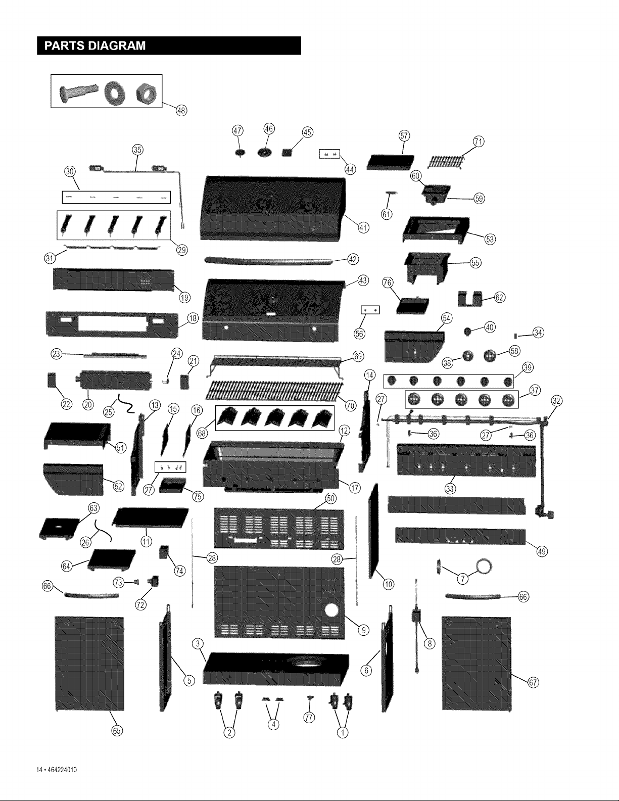
PartsList.......................................... 13
PartsDiagram...................................... 14
Assembly....................................... 15-32
Troubleshooting.................................. 33-35
RepairProtectionAgreements
Congratulations on making a smart purchase. Your new
Kenmore® product is designed and manufactured for years of
dependable operation. But like all products, it may require repair
from time to time. That's when having a Repair Protection
Agreement can save you money and aggravation.
Here's what the Repair Protection Agreement* includes:
[] Expert service by our 10,000 professional repair specialists
[] Unlimited service and no charge for parts and labor on all
covered repairs
[] Product replacement up to $1500 if your covered product
can't be fixed
[] Discount of 10% from regular price of service and related
installed parts not covered by the agreement; also, 10% off
regular price of preventive maintenance check
[] Fast help by phone - we call it Rapid Resolution -
phone support from a Sears representative. Think of us
as a "talking owner's manual."
Once you purchase the Repair Protection Agreement, a
simple phone call is all that it takes for you to schedule service.
You can call anytime day or night, or schedule a service
appointment online.
The Repair Protection Agreement is a risk-free purchase. If
you cancel for any reason during the product warranty period,
we will provide a full refund. Or, a prorated refund anytime after
the product warranty period expires. Purchase your Repair
Protection Agreement today!
Some limitations and exclusions apply. For prices and
additional information in the U.S.A. call 1-800-827-6655.
*Coverage in Canada varies on some items. For full details
call Sears Canada at 1-800-361-6665.
Sears installation Service
For Sears professional installation of home appliances, garage
door openers, water heaters, and other major home items, in the
U.S.A. or Canada call 1-800-4-MY-HOME®.
KENMORE GRILL WARRANTY
One Year Full Warranty on Kenmore Grill
If this grill fails due to a defect in material or workmanship
within one year from the date of purchase, call 1-800-4-MY-
HOME®to arrange for free repair (or replacement if repair
proves impossible).
Ten-Year Limited Warranty on Burners
For ten years from the date of purchase, any burner that
rusts through will be replaced free of charge. After the first
year from the date of purchase, you pay for labor if you wish
to have it installed.
All warranty coverage excludes ignitor batteries and grill part
paint loss, discoloration or surface rusting, which are either
expendable parts that can wear out from normal use within
the warranty period, or are conditions that can be the result
of normal use, accident or improper maintenance.
All warranty coverage is void if this grill is ever used for
commercial or rental purposes.
All warranty coverage applies only if this grill is used in the
United States.
This warranty gives you specific legal rights, and you may
also have other rights which vary from state to state.
Sears, Roebuck and Co., Hoffman Estates, IL 60179
CONVERSION READY
This grill easily converts from LP
liquid propane to NG natural gas.
Contact 1-800-4-MY-HOME®or
www.sears.com to purchase a
natural gas conversion kit, part
number 415.7116572.
Dual FuerrMis a registered trademarks of the W. C. Bradley
Company and used, with permission, by Sears Holdings
Corporation. All rights reserved.
464224010" 3
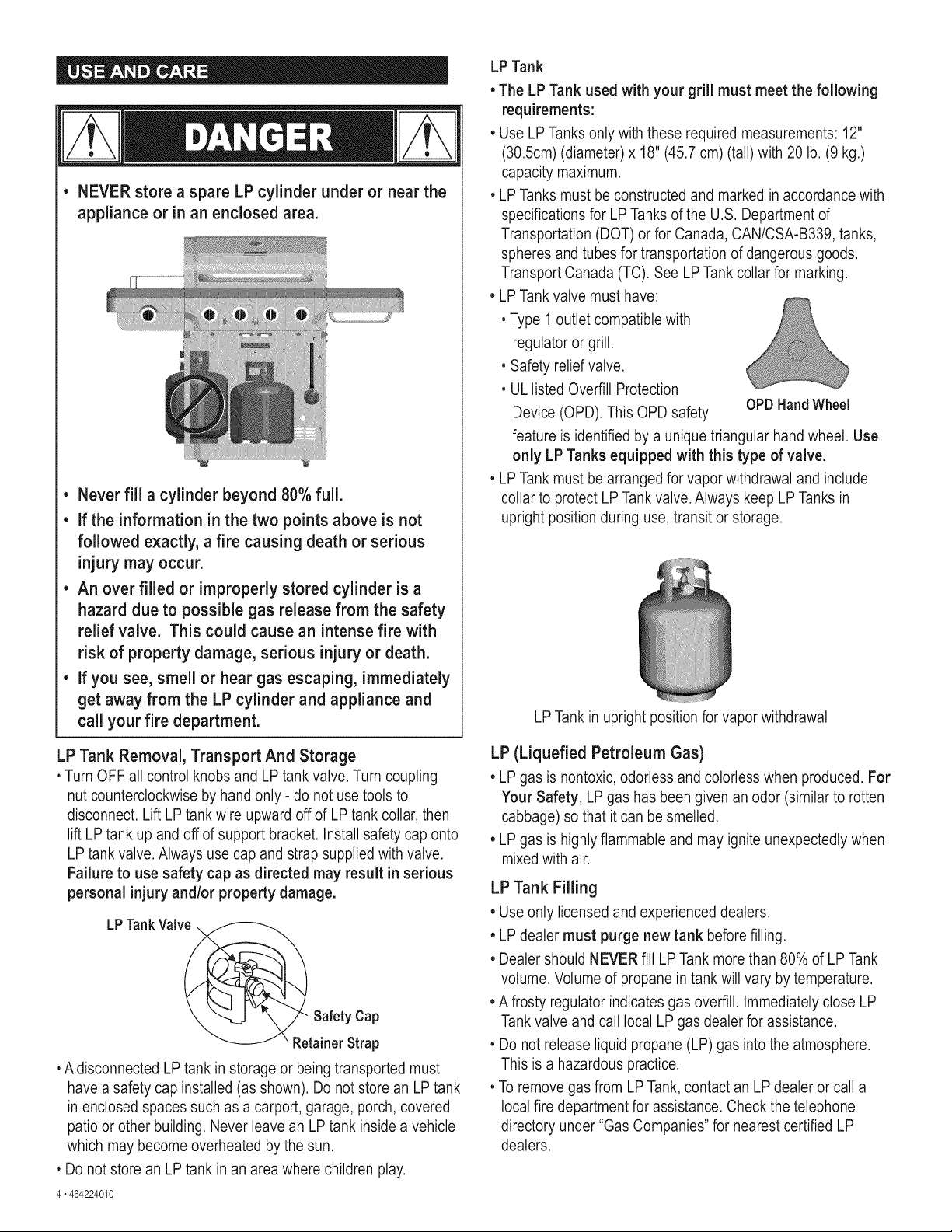
• NEVER store a spare LP cylinder under or near the
appliance or in an enclosed area.
• Never fill a cylinder beyond 80% full.
• If the information in the two points above is not
followed exactly, a fire causing death or serious
injury may occur.
• An over filled or improperly stored cylinder is a
hazard due to possible gas release from the safety
relief valve. This could cause an intense fire with
risk of property damage, serious injury or death.
• If you see, smell or hear gas escaping, immediately
get away from the LP cylinder and appliance and
call your fire department.
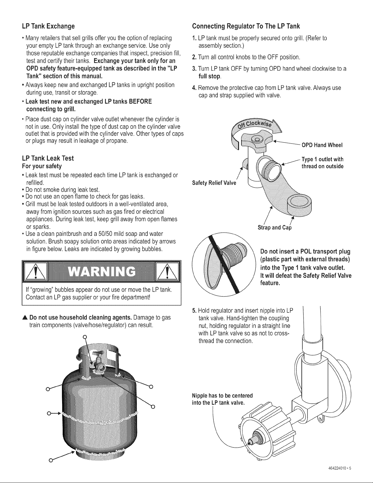
LP Tank Removal, Transport And Storage
• Turn OFF all control knobs and LP tank valve. Turn coupling
nut counterclockwise by hand only - do not use tools to
disconnect. Lift LP tank wire upward off of LP tank collar, then
lift LP tank up and off of support bracket. Install safety cap onto
LP tank valve. Always use cap and strap supplied with valve.
Failure to use safety cap as directed may result in serious
personal injury and/or property damage.
LPTankValve.
Safety Cap
RetainerStrap
• A disconnected LP tank in storage or being transported must
have a safety cap installed (as shown). Do not store an LPtank
in enclosed spaces such as a carport, garage, porch, covered
patio or other building. Never leave an LP tank inside a vehicle
which may become overheated by the sun.
• Do not store an LP tank in an area where children play.
4" 464224010
LP Tank
• The LP Tank used with your grill must meet the following
requirements:
• Use LP Tanks only with these required measurements: 12"
(30.5cm) (diameter) x 18" (45.7 cm) (tall) with 20 lb. (9 kg.)
capacity maximum.
• LP Tanks must be constructed and marked in accordance with
specifications for LP Tanks of the U.S. Department of
Transportation (DOT) or for Canada, CAN/CSA-B339, tanks,
spheres and tubes for transportation of dangerous goods.
Transport Canada (TC). See LP Tank collar for marking.
• LP Tank valve must have:
• Type 1 outlet compatible with
regulator or grill.
• Safety relief valve.
• UL listed Overfill Protection
Device (OPD). This OPD safety OPDHandWheel
feature is identified by a unique triangular hand wheel. Use
only LP Tanks equipped with this type of valve.
• LP Tank must be arranged for vapor withdrawal and include
collar to protect LPTank valve. Always keep LP Tanks in
upright position during use, transit or storage.
LP Tank in upright position for vapor withdrawal
LP (Liquefied Petroleum Gas)
• LP gas is nontoxic, odorless and colorless when produced. For
Your Safety, LP gas has been given an odor (similar to rotten
cabbage) so that it can be smelled.
• LP gas is highly flammable and may ignite unexpectedly when
mixedwith air.
LP Tank Filling
• Use only licensed and experienced dealers.
LP dealer must purge new tank before filling.
• Dealer should NEVER fill LPTank more than 80% of LP Tank
volume. Volume of propane in tank will vary by temperature.
• A frosty regulator indicates gas overfill. Immediately close LP
Tankvalve and call local LP gas dealer for assistance.
• Do not release liquid propane (LP) gas into the atmosphere.
This is a hazardous practice.
• To remove gas from LP Tank, contact an LP dealer or call a
local fire department for assistance. Check the telephone
directory under "Gas Companies" for nearest certified LP
dealers.
LPTank Exchange
• Many retailers that sell grills offer you the option of replacing
your empty LP tank through an exchange service. Use only
those reputable exchange companies that inspect, precision fill,
test and certify their tanks. Exchange your tank only for an
OPD safety feature-equipped tank as described in the "LP
Tank" section of this manual.
• Always keep new and exchanged LP tanks in upright position
during use, transit or storage.
• Leak test new and exchanged LP tanks BEFORE
connecting to grill.
• Place dust cap on cylinder valve outlet whenever the cylinder is
not in use. Only install the type of dust cap on the cylinder valve
outlet that is provided with the cylinder valve. Other types of caps
or plugs may result in leakage of propane.
LP Tank Leak Test
For your safety
• Leak test must be repeated each time LP tank is exchanged or
refilled.
• Do not smoke during leak test.
• Do not use an open flame to check for gas leaks.
• Grill must be leak tested outdoors in a well-ventilated area,
away from ignition sources such as gas fired or electrical
appliances. During leak test, keep grill away from open flames
or sparks.
• Use a clean paintbrush and a 50/50 mild soap and water
solution. Brush soapy solution onto areas indicated by arrows
in figure below. Leaks are indicated by growing bubbles.
If "growing" bubbles appear do not use or move the LP tank.
Contact an LP gas supplier or your fire department!
A Do not use household cleaning agents. Damage to gas
train components (valve/hose/regulator) can result.
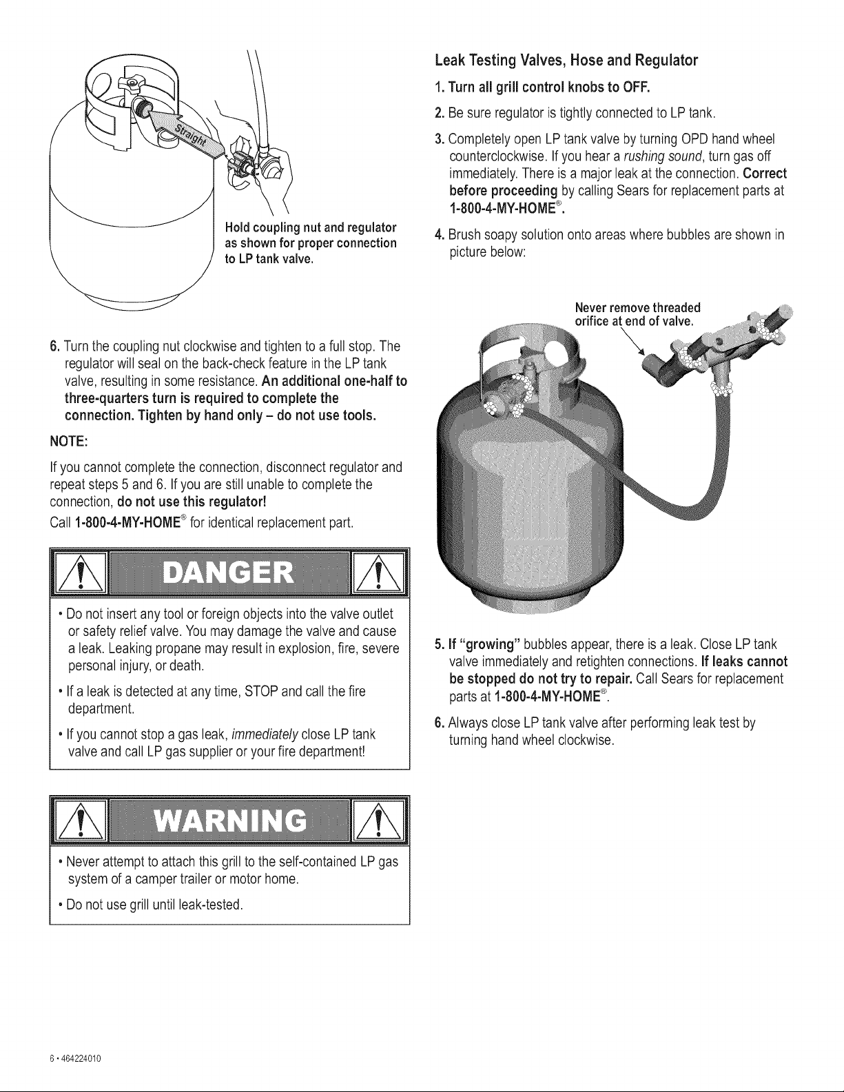
Connecting Regulator To The LP Tank
1. LP tank must be properly secured onto grill. (Refer to
assembly section.)
2. Turn all control knobs to the OFF position.
3. Turn LP tank OFF by turning OPD hand wheel clockwise to a
full stop.
4. Remove the protective cap from LPtank valve. Always use
cap and strap supplied with valve.
OPDHandWheel
//- Type1 outlet with
thread on outside
Safety Relief Valve
/
Strap and Cap
Do not insert a POL transport plug
(plastic part with external threads)
into the Type I tank valve outlet.
It will defeat the Safety Relief Valve
feature.
5. Hold regulator and insert nipple into LP
tank valve. Hand-tighten the coupling
nut, holding regulator in a straight line
with LP tank valve so as not to cross-
thread the connection.
Nipple has to be centered
intothe LPtank valve.
464224010• 5
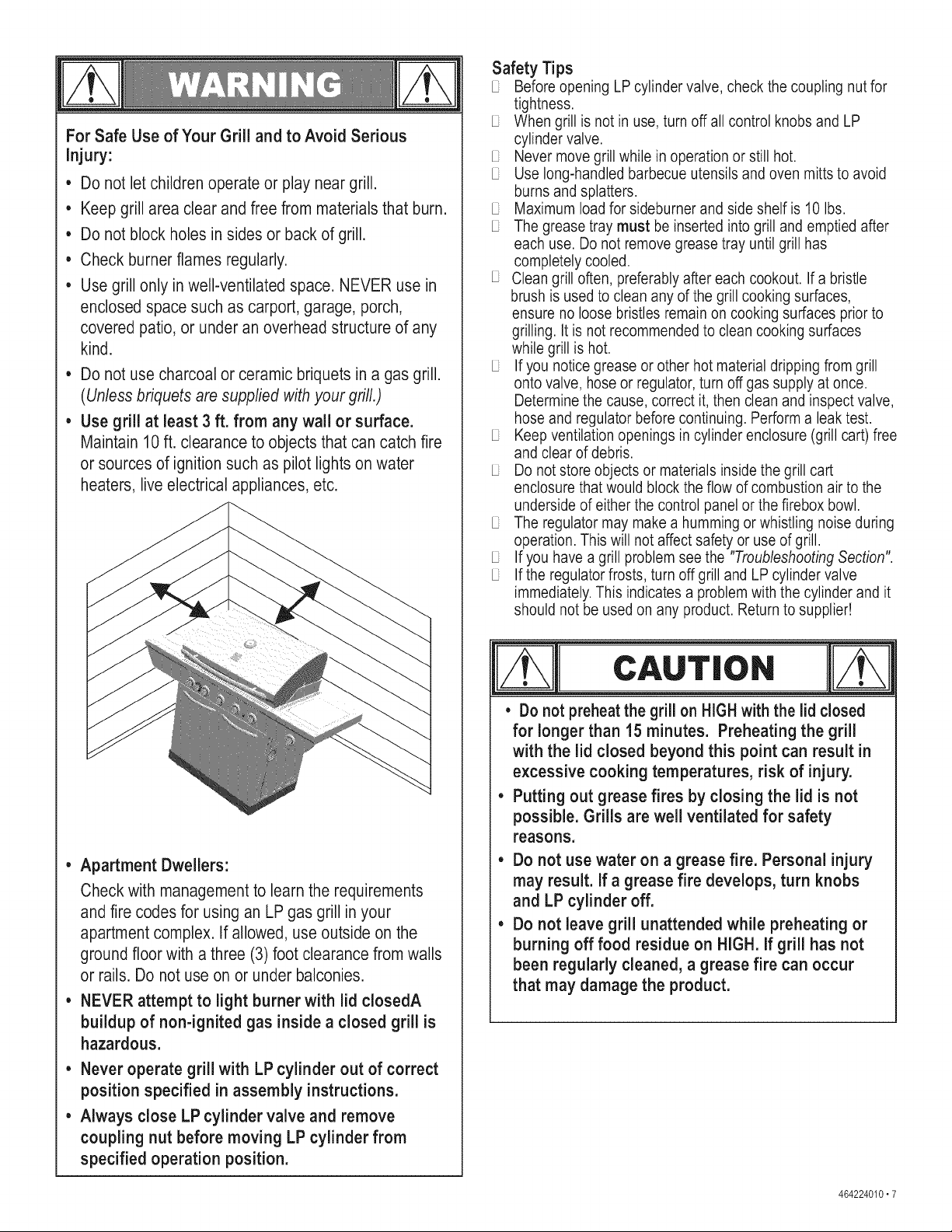
Hold coupling nut and regulator
as shownfor properconnection
to LPtank valve.
Leak Testing Valves, Hose and Regulator
1. Turn all grill control knobs to OFF.
2. Be sure regulator is tightly connected to LP tank.
3. Completely open LPtank valve by turning OPD hand wheel
counterclockwise. If you hear a rushing sound, turn gas off
immediately. There is a major leak at the connection. Correct
before proceeding by calling Sears for replacement parts at
1-800-4-MY-HOME®.
4. Brush soapy solution onto areas where bubbles are shown in
picture below:
6. Turn the coupling nut clockwise and tighten to a full stop. The
regulator will seal on the back-check feature in the LP tank
valve, resulting in some resistance. An additional one-half to
three-quarters turn is required to complete the
connection. Tighten by hand only - do not use tools.
NOTE:
If you cannot complete the connection, disconnect regulator and
repeat steps 5 and 6. If you are still unable to complete the
connection, do not use this regulator!
Call ®
1-800-4-MY-HOME for identical replacement part.
• Do not insert any tool or foreign objects into the valve outlet
or safety relief valve. You may damage the valve and cause
a leak. Leaking propane may result in explosion, fire, severe
personal injury,or death.
• If a leak is detected at any time, STOP and call the fire
department.
• If you cannot stop a gas leak, immediately close LP tank
valve and call LP gas supplier or your fire department!
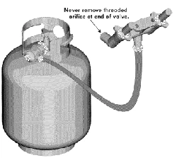
Neverremovethreaded
orificeat end of valve.
5. If "growing" bubbles appear, there is a leak. Close LP tank
valve immediately and retighten connections. If leaks cannot
be stopped do not try to repair. Call Sears for replacement
parts at 1-800-4-MY-HOME®.
6. Always close LP tank valve after performing leak test by
turning hand wheel clockwise.
• Never attempt to attach this grill to the self-contained LP gas
system of a camper trailer or motor home.
• Do not use grill until leak-tested.
6 • 464224010
For Safe Use of YourGrill and to Avoid Serious
injury:
• Do not let children operate or play near grill.
• Keep grill area clear and free from materials that burn.
• Do not block holes in sides or back of grill.
• Check burnerflames regularly.
• Use grill only inwell-ventilated space. NEVER use in
enclosed space such as carport, garage, porch,
covered patio, or under an overhead structure of any
kind.
Do not use charcoal or ceramic briquets in a gas grill.
(Unless briquets are supplied with your grill.)
Use grill at least 3 ft. from any wall or surface.
Maintain 10 ft. clearance to objects that can catch fire
or sources of ignition such as pilot lights on water
heaters, live electrical appliances, etc.
• Apartment Dwellers:
Check with managementto learn the requirements
and fire codes for using an LP gas grill in your
apartment complex. If allowed, use outside on the
ground floor with a three (3) foot clearance from walls
or rails. Do not use on or under balconies.
• NEVER attempt to light burner with lid closedA
buildup of non-ignited gas inside a closed grill is
hazardous.
• Never operate grill with LP cylinder out of correct
positionspecified in assembly instructions.
• Always close LP cylinder valve and remove
coupling nut before moving LP cylinder from
specified operation position.
Safety Tips
Before opening LP cylinder valve, check the coupling nut for
tightness.
When grill is not in use, turn off all control knobs and LP
cylinder valve.
Never move grill while in operation or still hot.
Use long-handled barbecue utensils and oven mitts to avoid
burns and splatters.
Maximum load for sideburner and side shelf is 10 Ibs.
The grease tray must be inserted into grill and emptied after
each use. Do not remove grease tray until grill has
completely cooled.
Clean grill often, preferably after each cookout. If a bristle
brush is used to clean any of the grill cooking surfaces,
ensure no loose bristles remain on cooking surfaces prior to
grilling. It is not recommended to clean cooking surfaces
while grill is hot.
If you notice grease or other hot material dripping from grill
onto valve, hose or regulator, turn off gas supply at once.
Determine the cause, correct it, then clean and inspect valve,
hose and regulator before continuing. Perform a leak test.
Keep ventilation openings in cylinder enclosure (grill cart) free
and clear of debris.
Do not store objects or materials inside the grill cart
enclosure that would block the flow of combustion air to the
underside of either the control panel or the firebox bowl.
The regulator may make a humming or whistling noise during
operation. This will not affect safety or use of grill.
If you have a grill problem see the "Troubleshooting Section".
If the regulator frosts, turn off grill and LP cylinder valve
immediately. This indicates a problem with the cylinder and it
should not be used on any product. Return to supplier!
CAuT,o.
, Do not preheat the grill on HIGHwiththe lid closed
for longer than 15 minutes. Preheating the grill
with the lid closed beyond this point can result in
excessive cooking temperatures, risk of injury.
• Putting out grease fires by closing the lid is not
possible. Grills are well ventilated for safety
reasons.
,, Do not use water on a grease fire. Personal injury
may result. If a grease fire develops, turn knobs
and LP cylinder off.
• Do not leave grill unattended while preheating or
burning off food residue on HIGH. If grill has not
been regularly cleaned, a grease fire can occur
that may damage the product.
464224010,7
Main Burner ignitor Lighting
Do not lean over grill while lighting.
1. Turn OFF all Gas Burner Control Valves.
2. Turn ON gas at LP cylinder.
3. Open main burner lid during Lighting.
4. To ignite any main burner, push in and turn the burner control
knob to the ,_ position. You will hear a clicking sound as the
burner is being ignited.
5. Once burner has ignited, turn knob to desired setting.
6. If Ignition does not occur in 5 seconds, turn the burner control
to OFF, wait 5 minutes for gas to clear away, and repeat the
lighting procedure.
7. Repeat steps 4 through 6 for the remaining main burners.
Searing Sideburner ignitor Lighting
Do not lean over grill while lighting.
1. Open sideburner lid during lighting, Turn on gas at LP
cylinder.
2. Push in and turn control knob to ,,_. You will hear a clicking
sound as the burner is being ignited. Ignition should occur
within 5 seconds, but leave the knob in the _ position for a
full 10 seconds to maintain ignition.
3. Once burner has ignited, turn knob to desired setting.
4. If ignition does NOT occur in 5 seconds, turn the burner
control OFF. Wait 5 minutes for gas to clear away, and repeat
the lighting procedure.
Rotisserie Burner ignitor Lighting
Do not lean over grill while lighting.
1. Open main burner lid during lighting. Turn on gas at LP
cylinder.
2. Push in and turn control knob to _ . Youwill hear a clicking
sound as the burner is being ignited. Ignition should occur
within 5 seconds, but leave the knob in the _ position for a
full 10 seconds to maintain ignition.
3. Once burner has ignited, turn knob to desired setting.
4. If ignition does NOT occur in 5 seconds, turn the burner
control OFF. Wait 5 minutes for gas to clear away, and repeat
the lighting procedure.
Match-Lighting
Do not lean over grill while lighting.
Open lid. Turn on gas at LP cylinder.
Light Burners one at time.
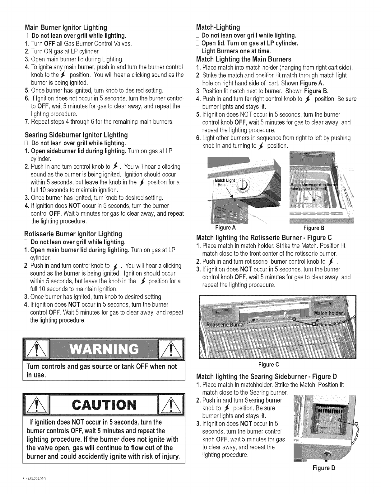
Match Lighting the Main Burners
1. Place match into match holder (hanging from right cart side).
2. Strike the match and position lit match through match light
hole on right hand side of cart. Shown Figure A.
3. Position lit match next to burner. Shown Figure B.
4. Push in and turn far right control knob to _ position. Be sure
burner lights and stays lit.
5. If ignition does NOT occur in 5 seconds, turn the burner
control knob OFF, wait 5 minutes for gas to clear away, and
repeat the lighting procedure.
6. Light other burners in sequence from right to left by pushing
knob in and turning to _ position.
Match
Hok
FigureA
Figure B
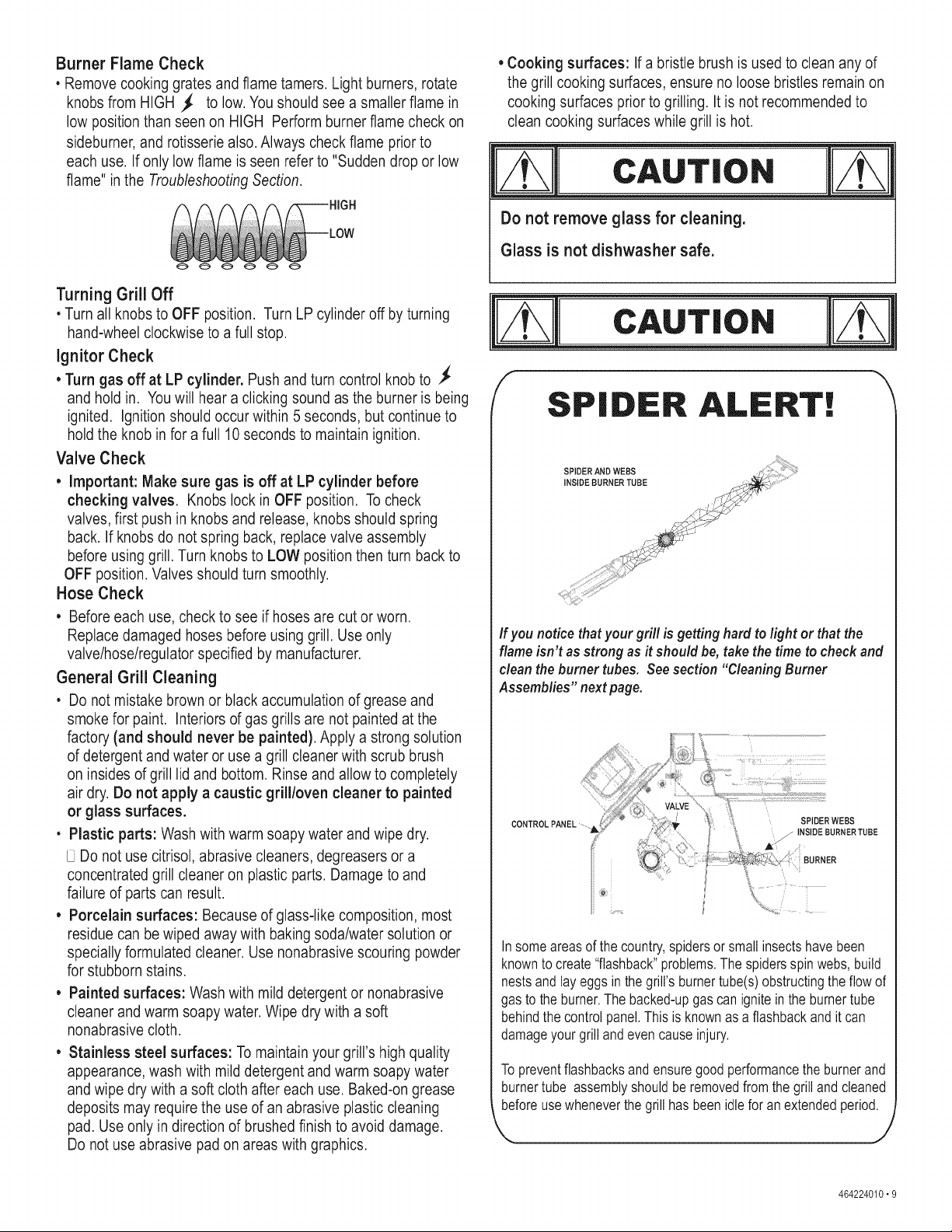
Match lighting the Rotisserie Burner- Figure C
1. Place match in match holder. Strike the Match. Position lit
match close to the front center of the rotisserie burner.
2. Push in and turn rotisserie burner control knob to
3. If ignition does NOT occur in 5 seconds, turn the burner
control knob OFF, wait 5 minutes for gas to clear away, and
repeat the lighting procedure.
Turn controls and gas source or tank OFF when not
in use.
CAUTION
If ignitiondoes NOToccurin 5 seconds, turn the
burner controlsOFF,wait 5 minutesand repeat the
lighting procedure. If the burner does not ignite with
the valve open, gas will continue to flow out of the
burner and could accidently ignite with risk of injury.
Figure C
Match lighting the Searing Sideburner- Figure D
1. Place match in matchholder. Strike the Match. Position lit
match close to the Searing burner.
2. Push in and turn Searing burner
knob to _ position. Be sure
burner lights and stays lit.
3. If ignition does NOT occur in 5
seconds, turn the burner control
knob OFF, wait 5 minutes for gas ___._.
to clear away, and repeat the
lighting procedure.
8.464224010
Figure D
Burner Flame Check
• Remove cooking grates and flame tamers. Light burners, rotate
knobs from HIGH _ to low. You should see a smaller flame in
low position than seen on HIGH Perform burner flame check on
sideburner, and rotisserie also. Always check flame prior to
each use. If only low flame is seen refer to "Sudden drop or low
flame" in the Troubleshooting Section.
Turning Grill Off
• Turn all knobs to OFF position. Turn LP cylinder off by turning
hand-wheel clockwise to a full stop.
Ignitor Check
• Turn gas off at LP cylinder. Push and turn control knob to ._
and hold in. Youwill hear a clicking sound as the burner is being
ignited. Ignition should occur within 5 seconds, but continue to
hold the knob in for a full 10 seconds to maintain ignition.
Valve Check
• Important: Make sure gas is off at LP cylinder before
checking valves. Knobs lock in OFF position. To check
valves, first push in knobs and release, knobs should spring
back. If knobs do not spring back, replace valve assembly
before using grill. Turn knobs to LOW position then turn back to
OFF position. Valves should turn smoothly.
Hose Check
• Before each use, check to see if hoses are cut or worn.
Replace damaged hoses before using grill. Use only
valve/hose/regulator specified by manufacturer.
General Grill Cleaning
• Do not mistake brown or black accumulation of grease and
smoke for paint. Interiors of gas grills are not painted at the
factory (and should never be painted). Apply a strong solution
of detergent and water or use a grill cleaner with scrub brush
on insides of grill lid and bottom. Rinse and allow to completely
air dry. Do not apply a caustic grill/oven cleaner to painted
or glass surfaces.
• Plastic parts: Wash with warm soapy water and wipe dry.
Do not use citrisol, abrasive cleaners, degreasers or a
concentrated grill cleaner on plastic parts. Damage to and
failure of parts can result.
• Porcelain surfaces: Because of glass-like composition, most
residue can be wiped away with baking soda/water solution or
specially formulated cleaner. Use nonabrasive scouring powder
for stubborn stains.
• Painted surfaces: Wash with mild detergent or nonabrasive
cleaner and warm soapy water. Wipe dry with a soft
nonabrasive cloth.
• Stainless steel surfaces: To maintain your grill's high quality
appearance, wash with mild detergent and warm soapy water
and wipe dry with a soft cloth after each use. Baked-on grease
deposits may require the use of an abrasive plastic cleaning
pad. Use only in direction of brushed finish to avoid damage.
Do not use abrasive pad on areas with graphics.
• Cooking surfaces: Ifa bristle brush is used to clean any of
the grill cooking surfaces, ensure no loose bristles remain on
cooking surfaces prior to grilling. It is not recommended to
clean cooking surfaces while grill is hot.
CAUTION
Do not remove glass for cleaning.
Glass is not dishwasher safe.
ciuT,o.
/ SPIDER ALERT! "
If you notice thatyour grill is getting hard to light or that the
flameisn't as strong as it should be, take thetimeto check and
clean the burner tubes. Seesection "Cleaning Burner
Assemblies" nextpage.
CONTROLPANEL--
SPIDERWEBS
_ INSIDE BURNERTUBE
BURNER
In someareasof the country,spidersor small insectshave been
knownto create"flashback"problems.The spidersspinwebs,build
nestsandlayeggs inthe grill'sburnertube(s)obstructingthe flowof
gasto theburner.Thebacked-upgascan igniteinthe burnertube
behindthecontrolpanel.Thisis knownas a flashbackandit can
damageyourgrilland evencause injury.
Topreventflashbacksand ensuregoodperformancetheburnerand
burnertube assemblyshouldberemovedfromthe grillandcleaned
beforeusewheneverthegrill hasbeenidlefor an extendedperiod.
\ J
464224010"9
Cleaning the Burner Assembly
Follow these instructions to clean and/or replace parts of burner
assembly or if you have trouble igniting grill.
1. Turn gas off at control knobs and LP Tank.
2. Remove cooking grates and heat diffusers.
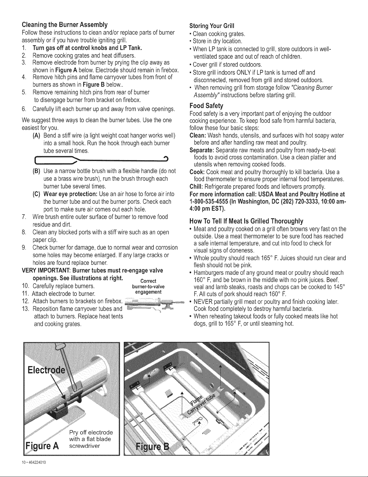
3. Remove electrode from burner by prying the clip away as
shown in Figure A below. Electrode should remain in firebox.
4. Remove hitch pins and flame carryover tubes from front of
burners as shown in Figure B below..
5. Remove remaining hitch pins from rear of burner
to disengage burner from bracket on firebox.
6. Carefully lift each burner up and away from valve openings.
We suggest three ways to clean the burner tubes. Use the one
easiest for you.
(A) Bend a stiff wire (a light weight coat hanger works well)
into a small hook. Run the hook through each burner
tube several times.
(B) Use a narrow bottle brush with a flexible handle (do not
use a brass wire brush), run the brush through each
burner tube several times.
(C) Wear eye protection: Use an air hose to force air into
the burner tube and out the burner ports. Check each
port to make sure air comes out each hole.
7. Wire brush entire outer surface of burner to remove food
residue and dirt.
8. Clean any blocked ports with a stiff wire such as an open
paper clip.
9. Check burner for damage, due to normal wear and corrosion
some holes may become enlarged. Ifany large cracks or
holes are found replace burner.
VERY iMPORTANT:Burner tubes must re-engage valve
openings. See illustrations at right. Correct
10. Carefully replace burners, burner-to-valve
11. Attach electrode to burner, engagement
12. Attach burners to brackets on firebox. ................
13. Reposition flame carryover tubes and
attach to burners. Replace heat tents
and cooking grates.
Storing Your Grill
• Clean cooking grates.
• Store in dry location.
• When LP tank is connected to grill, store outdoors in well-
ventilated space and out of reach of children.
• Cover grill if stored outdoors.
• Store grill indoors ONLY if LP tank is turned off and
disconnected, removed from grill and stored outdoors.
• When removing grill from storage follow "Cleaning Burner
Assembly" instructions before starting grill.
Food Safety
Food safety is a very important part of enjoying the outdoor
cooking experience. To keep food safe from harmful bacteria,
follow these four basic steps:
Clean: Wash hands, utensils, and surfaces with hot soapy water
before and after handling raw meat and poultry.
Separate: Separate raw meats and poultry from ready-to-eat
foods to avoid cross contamination. Use a clean platter and
utensils when removing cooked foods.
Cook: Cook meat and poultry thoroughly to kill bacteria. Use a
food thermometer to ensure proper internal food temperatures.
Chill: Refrigerate prepared foods and leftovers promptly.
For more information call: USDA Meat and Poultry Hotline at
1-800-535-4555 (In Washington, DC (202) 720-3333, 10:00 am-
4:00 pm EST).
How To Tell If Meat Is Grilled Thoroughly
• Meat and poultry cooked on a grill often browns very fast on the
outside. Use a meat thermometer to be sure food has reached
a safe internal temperature, and cut into food to check for
visual signs of doneness.
• Whole poultry should reach 165° F. Juices should run clear and
flesh should not be pink.
• Hamburgers made of any ground meat or poultry should reach
160° F, and be brown in the middle with no pink juices. Beef,
veal and lamb steaks, roasts and chops can be cooked to 145°
F.All cuts of pork should reach 160° F.
• NEVER partially grill meat or poultry and finish cooking later.
Cook food completely to destroy harmful bacteria.
• When reheating takeout foods or fully cooked meats like hot
dogs, grill to 165° F, or until steaming hot.
Pry off electrode
with a flat blade
A screwdriver
10"464224010
| Haic)ge. Lig
LIGHT OPERATION iNSTRUCTiONS
1. Make sure light switch on the control panel is in the "OFF" position.
2. Connect light plug to an extension cord, then put the extension
cord plug into the outlet on the wall.
3. Turn the light switch to "ON".
Keep any electrical supply cord away from any
heated surface.
Use the shortest length extension cord required.
Do not connect 2 or more extension cords together.
1. 2. 3.
Extension cord,
for out dooruse
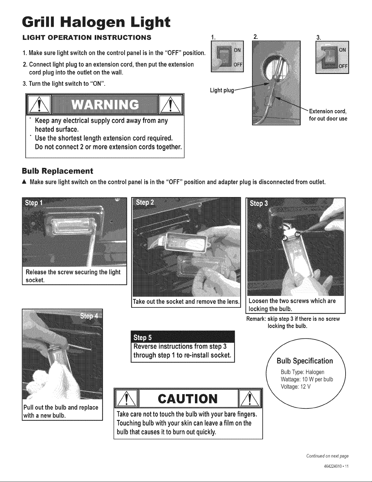
Bulb Replacement
A Make sure light switch on the control panel is in the "OFF" position and adapter plug is disconnected from outlet.
Release the screw securing the light
socket.
Take out the socket and remove the lens.
Loosen the two screws which are
locking the bulb.
Pull out the bulb and replace
with a new bulb.
Reverse instructionsfrom step 3
through step 1 to re-install socket.
Remark:skipstep3 if there isno screw
lockingthe bulb.
Takecarenotto touch the bulb with your barefingers.
Touchingbulb with your skin canleavea film on the
bulb that causesit to burn out quickly.
Bulb Specification
BulbType:Halogen
Wattage:10W per bulb
Voltage:12V
Continuedon nextpage
464224010•11
C|eaning the Lens
1. Prior to cleaning, make sure the light switch is in the "OFF" position and the light plug is
disconnected from the power supply.
2. Do not clean the glass lens when warm. Allow to cool before cleaning. Sudden change in
temperature may cause cracking of the glass lens.
3. Use a damp towel to clean the surface of the glass lens.
4. Allow the lens to dry before reconnecting the light plug to the power supply and turning the
light switch to the "ON" position.
I POITAq?
• Since 1971 the National Electric Code (NEC) has required Ground Fault Interrupter devices on all outdoor
circuits.
• If your residence was built before 1971, check with a qualified electrician to determine if a Ground Fault
Interrupter protector exists.
• Do not use this appliance if the circuit does not have GFI protection.
• Do not plug this appliance into an indoor circuit.
1. To protect against electric shock, do not immerse cord or plugs in water or other liquid.
2. Unplug from the outlet when not in use and before cleaning. Allow to cool before putting on or taking off parts.
3. Do not operate grill with a damaged cord, plug, or after the appliance malfunctions or has been damaged in any manner.
4. Do not let the cord hang over the edge of a table or touch hot surfaces.
5. Do not use an outdoor cooking gas appliance for purposes other than intended.
6. When connecting, first connect plug to the outdoor cooking gas appliance then plug appliance into the outlet.
7. Use only a Ground Fault Interrupter(GFI) protected circuit with this outdoor cooking gas appliance.
8. Never remove the grounding plug or use with an adapter of 2 prongs.
9. Use only extension cords with a 3 prong grounding plug, rated for the power of the equipment, and approved for
outdoor use with a W-A marking.
464224010"12

1 2 LOCKING CASTER G401-0061-W1
2 2 FIXED CASTER G606-0027-W1
3 1 BOTTOM SHELF G614-A300-W1
4 2 DOOR MAGNET ASSEMBLY G501-0016-W1
5 1 LEFT SIDE PANEL G614-A100-W1
6 1 RIGHT SIDE PANEL G614-A200-W1
7 2 GROMMET G501-0039-W1
8 1 12 VOLT ADAPTER G518-0076-W1
9 1 LOWER BACK PANEL G614-0072-W1
10 1 CART PARTITION PANEL G614-0082-W1
11 1 INSIDE SHELF G614-0083-W1
12 1 FIREBOX G614-4200-W1
13 1 LEFT PANEL, OUTER FIREBOX G614-1700-W1
14 1 RIGHT PANEL, OUTER FIREBOX G614-1800-W1
15 1 LEFT PANEL, INNER FIREBOX G614-0200-W1
16 1 RIGHT PANEL, INNER FIREBOX G614-0300-W1
17 1 HEAT SHIELD, FIREBOX G614-0047-W1
18 1 REAR UPPER PANEL, FIREBOX G614-0048-W1
19 1 BACK COVER, ROTISSERIE G614-0049-W1
BURNER
20 1 ROTISSERIE BURNER G614-1900-W1
21 1 RIGHT WIND SHIELD, ROTISSERIE G614-0052-W1
BURNER
22 1 LEFT WIND SHIELD, ROTISSERIE G614-0053-W1
BURNER
23 1 UPPER WIND SHIELD, G614-0093-W1
ROTISSERIE BURNER
24 1 ELECTRODE, F/ROTISSERIE G614-0094-W1
25 1 ELECTRODE WIRE, F/ROTISSERIE G614-0059-W1
26 1 GROUND WIRE, F/El MODULE G411-0004-W1
27 6 HOSE CLIP G608-0041-Wl
28 2 MATCH HOLDER AND CHAIN G508-0039-W1
29 5 MAIN BURNER G614-A000-W1
30 5 ELECTRODE, F/MAIN BURNER, W/ G515-0014-W1
WIRE & COLLECTOR BOX
31 4 FLAME CARRYOVER TUBE G614-0095-W1
32 1 HOSE VALVE REGULATOR G614-7200-W1
33 1 CONTROL PANEL G614-0063-W1
34 1 LIGHT SWITCH G520-0013-W1
35 1 HALOGEN LIGHT ASSEMBLY G614-8200-W1
36 2 PIN, F/DOOR G411-0054-W1
37 5 BEZEL, F/CONTROL KNOB G614-0064-W1
38 1 BEZEL, F/ROTISSERIE KNOB G614-0065-W1
39 6 CONTROL KNOB G614-4400-W1
40 1 CONTROL KNOB, F/ROTISSERIE G614-2300-W1
41 1 TOP LID G614-1500-W1
42 1 HANDLE, F/TOP LID G614-0042-W1
43 1 INNER INSERT, F/TOP LID G614-0041-Wl
44 2 RUBBER BUMPER, G413-0025-W1
RECTANGULAR, F/LID
45 1 LOGO PLATE G528-0002-W1
46 1 BEZEL, F/TEMPERATURE GAUGE G503-0002-W1
47 1 TEMPERATURE GAUGE G518-0075-W1
48 1 HARDWARE F/TOP LID ASSEMBLY G508-0019-W1
49 1 FRONT BRACE G614-6300-W1
50 1 UPPER BACK PANEL, CART G614-0081-W1
51 1 LEFT SIDE SHELF G614-A800-W1
52 1 FASCIA, LEFT SHELF G614-0085-W1
53 1 RIGHT SIDEBURNER SHELF G614-A600-W1
54 1 FASCIA, F/SB SHELF G614-0074-W1
55 1 SIDEBURNER PAN G614-A700-W1
56 2 RUBBER BUMPER, ROUND, F/SB G501-0066-W1
LID
57 1 LID, F/SIDE BURNER G507-0011-W1
58 1 BEZEL, F/SIDEBURNER KNOB G614-0064-W2
59 1 SIDEBURNER G614-A500-W 1
60 1 ELECTRODE COVER, F/ G614-0080-W1
SIDEBURNER
61 1 ELECTRODE, F/SIDEBURNER G614-0092-W1
SIDEBURNER WINDSHIELD
62 1 G614-0073-W1
(HEATSHIELD)
63 1 GREASE TRAY HEAT SHIELD G614-A400-W1
64 1 TANK HEAT SHIELD G614-0084-W1
65 1 LEFT DOOR, NO HANDLE G614-2400-W1
66 2 DOOR HANDLE G614-0088-W1
67 1 RIGHT DOOR, NO HANDLE G614-3400-W1
68 5 HEAT DIFFUSER G614-0045-W1
69 1 WARMING RACK G614-0043-W1
70 5 COOKING GRATE, MAIN G614-0044-W1
71 1 SIDEBURNER GRATE G614-0090-W1
72 1 ELECTRONIC IGNITION MODULE G614-0070-W1
73 1 CAP, F/ELECTRONIC IGNITION G515-0030-W1
MODULE
74 1 HEAT SHIELD, F/ELECTRONIC G513-0040-W1
IGNITION MODULE
75 1 GREASE TRAY G507-4600-W1
76 1 SIDEBURNER GREASE TRAY G614-0075-W1
CYLINDER SCREW F/TANK
77 1 G505-0047-W 1
SECURE
NOT Picture:
NN N
... 1 CASTER WRENCH G413-0032-W1
... 1 HARDWARE PACK G614-B002-W1
... 1 ASSEMBLY MANUAL, ENGLISH G614-020801-W1
... 1 ASSEMBLY MANUAL, SPANISH G614-020802-W1
If you are missing hardware or have damaged parts after
unpacking grill, call 1-800-241-7548 for replacement.
Toorderreplacementpartsafter usinggrill, call
1-800-4-1ViY-HOIViE®
464224010.13
\
4_
14,464224010

D Attach the two locking casters at the rear of the bottom shelf
and the two fixed casters at the front using the supplied wrench.
Fixedcaster
Qty.lCasterwrench "_..,_
Lockingcaster
Bottom shelf
Attach side panels to bottom shelf using three
1/4-20x1/2" screws, 7ram lock washers and
7ram flat washers per panel.
IMPORTANT: Panel with large hole must
be on right side of bottom shelf.
1/4-20x1/2"screw
Qty.6
7ram lock washer
Qty.6
©
7ram flat washer
Qty.6
Leftside panel
Makesuresidepanels
are pushedas far to the
rearof bottom shelf as
possiblebeforefully
tightening screws.
1/4-20x1/2"screw
lock washer
fiat washer
_ Right side panel
(withlarge hole)
464224010.15
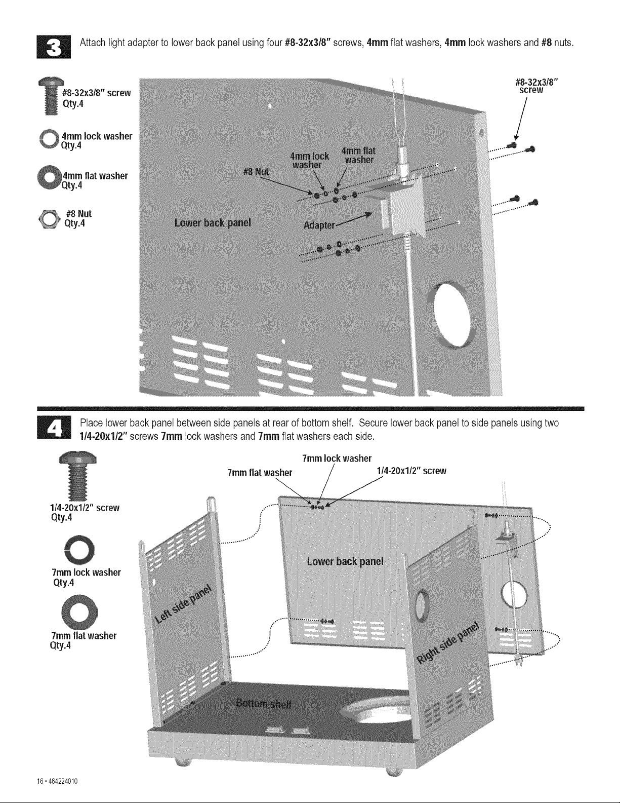
Attach light adapter to lower back panel using four #8-32x3/8" screws, 4ram flat washers, 4ram lock washers and #8 nuts.
#8-32x318"screw
Qty.4
4ram lock washer
Qty.4
#8-32x3/8"
screw
/
4ramflat washer
r.4
#8 Nut
Qty.4
.d
Place lower back panel between side panels at rear of bottom shelf. Secure lower back panel to side panels using two
1/4-20x1/2" screws 7ram lock washers and 7ram flat washers each side.
7ramflat washer
7ram lock washer
1/4-20x1/2"screw
1/4-20x1/2"screw
Qty.4 ""
7ramlock washer
Qty.4
0
7ramflat washer
Qty.4
16. 464224010
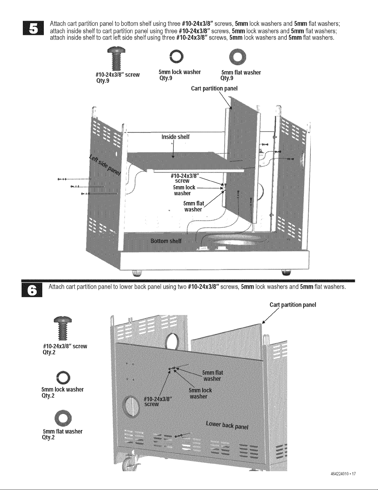
Attach cart partition panel to bottom shelf using three #10-24x3/8" screws, 5ram lock washers and 5ram flat washers;
attach inside shelf to cart partition panel using three #10-24x3/8" screws, 5ram lock washers and 5ram flat washers;
attach inside shelf to cart left side shelf using three #10-24x3/8" screws, 5ram lock washers and 5ram flat washers.
#10-24x3/8"screw 5ramlock washer 5ramflat washer
Qty.9 Qty.9 Qty.9
Cart partitionkpanel
Insideshelf
screw
5mrnlock
washer
Attach cart partition panel to lower back panel using two #10-24x3/8" screws, 5ram lock washers and 5ram flat washers.
Cart partition panel
F
#10-24x3/8"screw
Qty.2
5ram lock washer
Qty.2
5ramflat washer
Qty.2
464224010.17
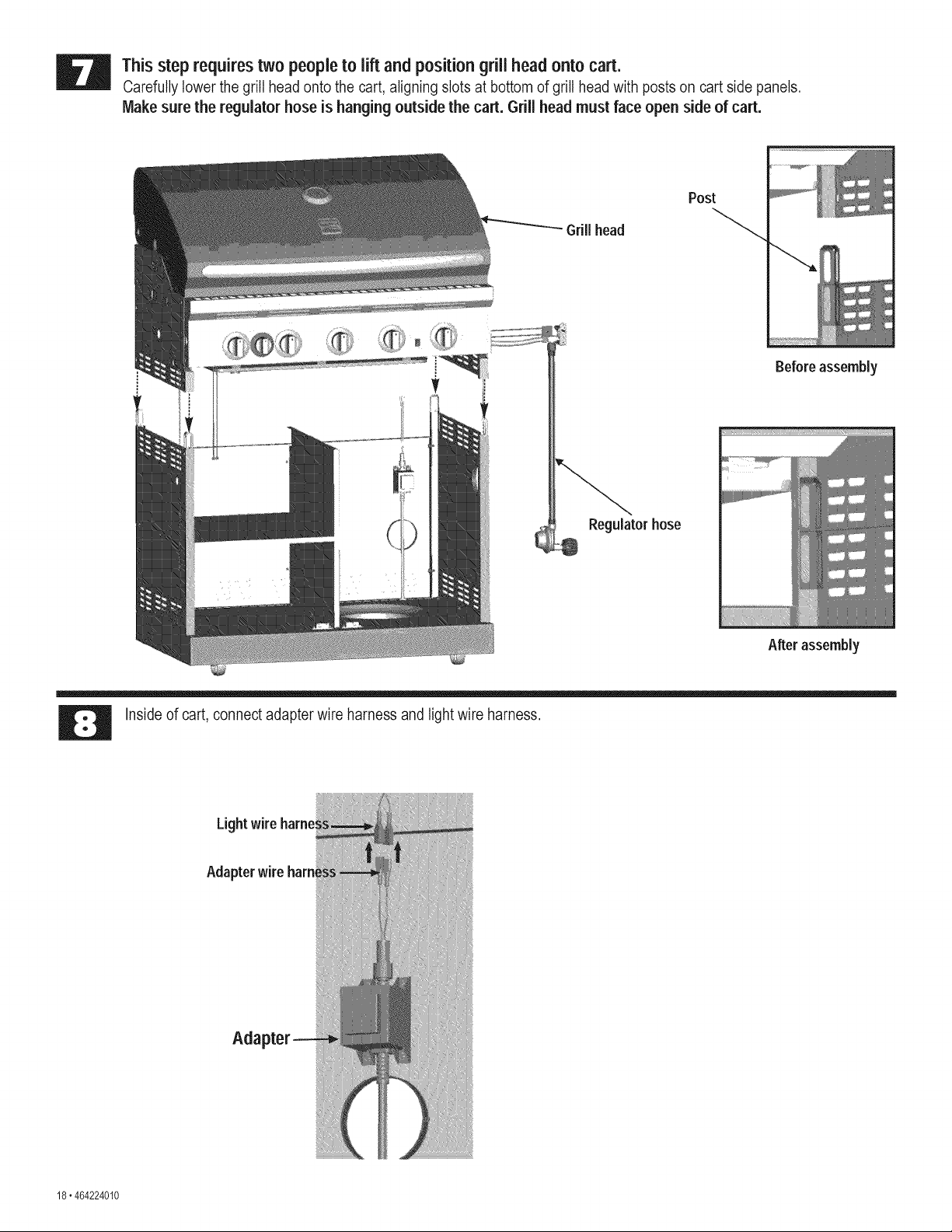
This step requires two people to lift and position grill head onto cart.
Carefully lower the grill head onto the cart, aligning slots at bottom of grill head with posts on cart side panels.
Make sure the regulator hose is hanging outside the cart. Grill head must face open side of cart.
GriBhead
Post
Regulator hose
O
Before assembly
After assembly
Inside of cart, connect adapter wire harness and light wire harness.
Lightwire
Adapter wire ham
Aria
18.464224010
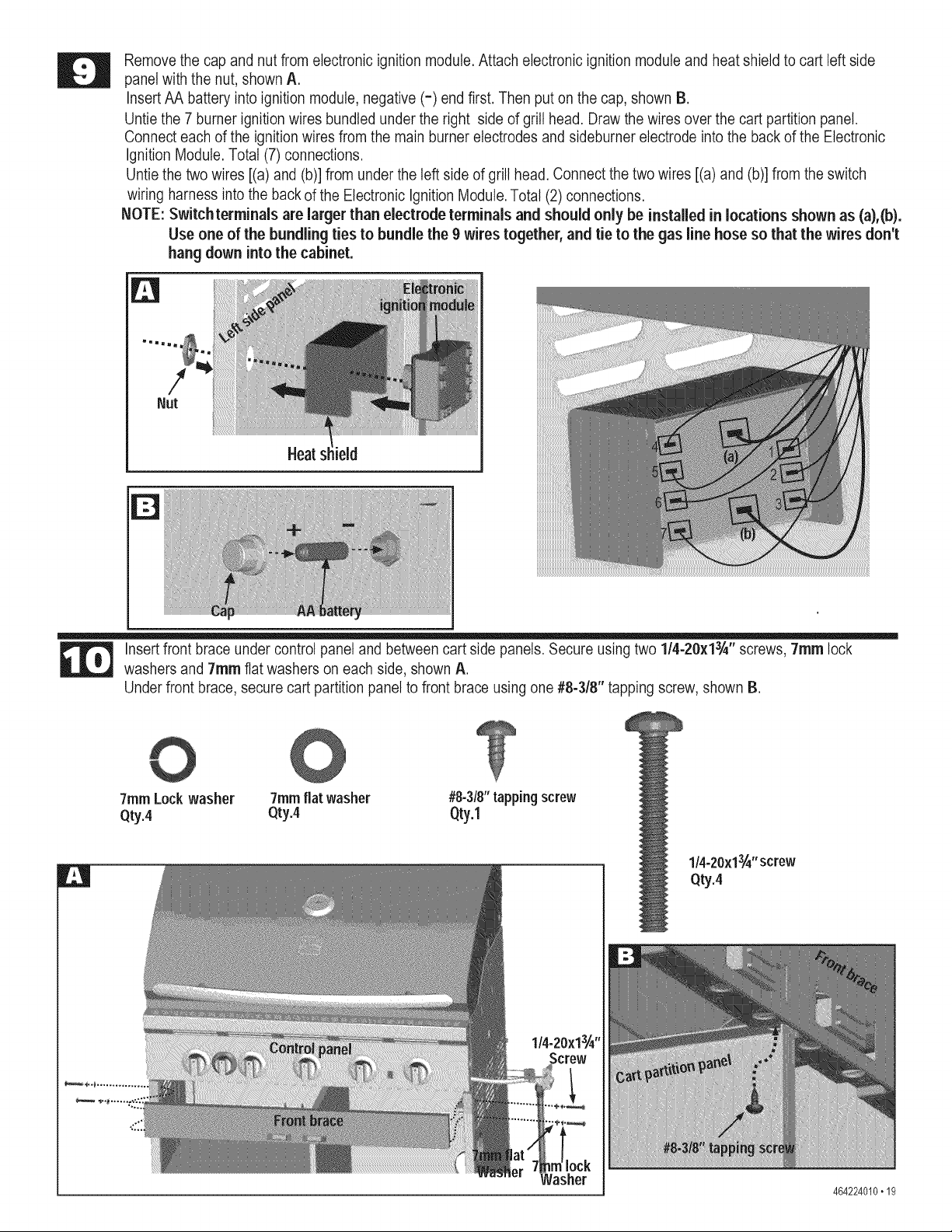
Remove the cap and nut from electronic ignition module. Attach electronic ignition module and heat shield to cart left side
panel with the nut, shown A.
Insert AA battery into ignition module, negative (=) end first. Then put on the cap, shown B.
Untie the 7 burner ignition wires bundled under the right side of grill head. Draw the wires over the cart partition panel.
Connect each of the ignition wires from the main burner electrodes and sideburner electrode into the back of the Electronic
Ignition Module. Total (7) connections.
Untie the two wires [(a) and (b)] from under the left side of grill head. Connect the two wires [(a) and (b)] from the switch
wiring harness into the back of the Electronic Ignition Module. Total (2) connections.
NOTE: Switchterminals are larger than electrode terminals and should only be installed in locations shown as (a),(b).
Use one of the bundling ties to bundle the 9 wires together, and tie to the gas line hose so that the wires don't
hang down into the cabinet.
!
Nut
Heat field
Insert front brace under control panel and between cart side panels. Secure using two 114-20x13/4'' screws, 7ram lock
washers and 7ram flat washers on each side, shown A.
Under front brace, secure cart partition panel to front brace using one #8-3/8" tapping screw, shown B.
7ramLockwasher #8-3/8"tapping screw
Qty.4 Qty.1
©
7ramflat washer
Qty.4
1/4-20x13A"screw
Qty.4
464224010.19
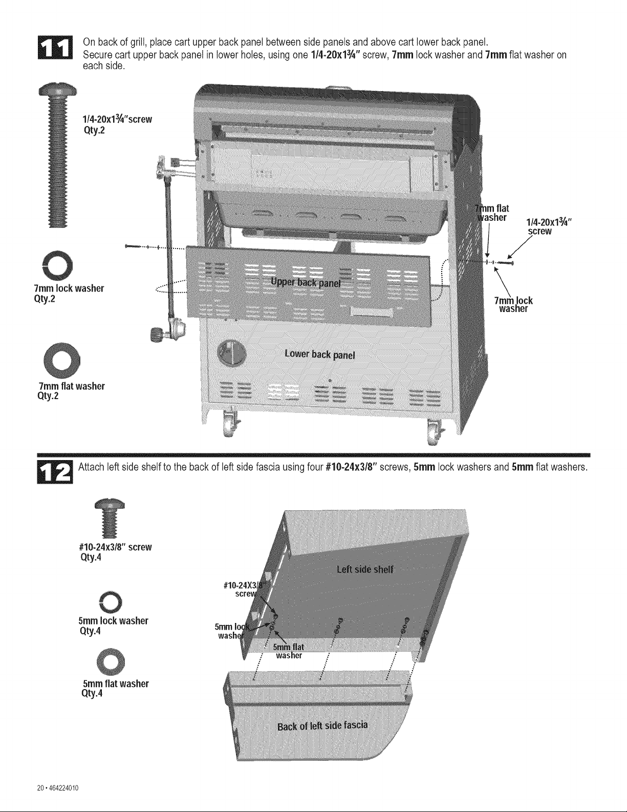
On back of grill, place cart upper back panel between side 3anels and above cart lower back panel.
Secure cart upper back panel in lower holes, using one 1/4-20x13/_'' screw, 7ram lock washer and 7ram flat washer on
each side.
1/4-20x13i_"screw
Qty.2
7ramlock washer
Qty.2 lock
washer
©
7ramflat washer
Qty.2
Attach left side shelf to the back of left side fascia using four #10-24x3/8" screws, 5ram lock washers and 5ram flat washers.
#10-24x3/8"screw
Qty.4
5ram lock washer
Qty.4 5ram
wash_
5ramflat washer
Qty.4
:" WaS .: :"
: / /
20.464224010
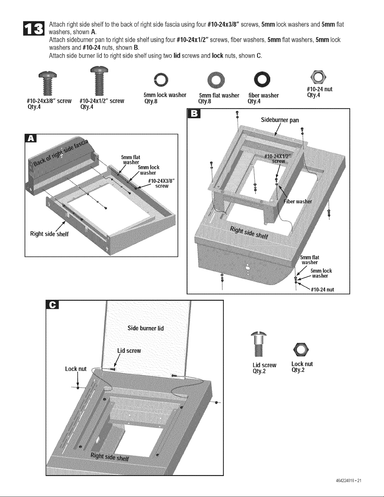
Attach right side shelf to the back of right side fascia using four #10-24x3/8" screws, 5ram lock washers and 5ram flat
washers, shown A.
Attach sideburner pan to right side shelf using four #10-24x1/2" screws, fiber washers, 5ram flat washers, 5ram lock
washers and #10-24 nuts, shown B.
Attach side burner lid to right side shelf using two lid screws and lock nuts, shown C.
#10-24x3/8"screw #10-24x1/2"screw
Qty.4 Qty.4
0
5ramfiat
washer
5ramlock
5ramlockwasher 5ramfiat washer fiber washer
Qty.8 Qty.8 Qty.4
#10-24X3/8"
screw
: Sideburner pan
#10-24nut
Qty.4
flat
washer
5turnlock
r,:J
Side burner lid
Locknut
Lidscrew
Qty.2
Locknut
Qty.2
464224010.21
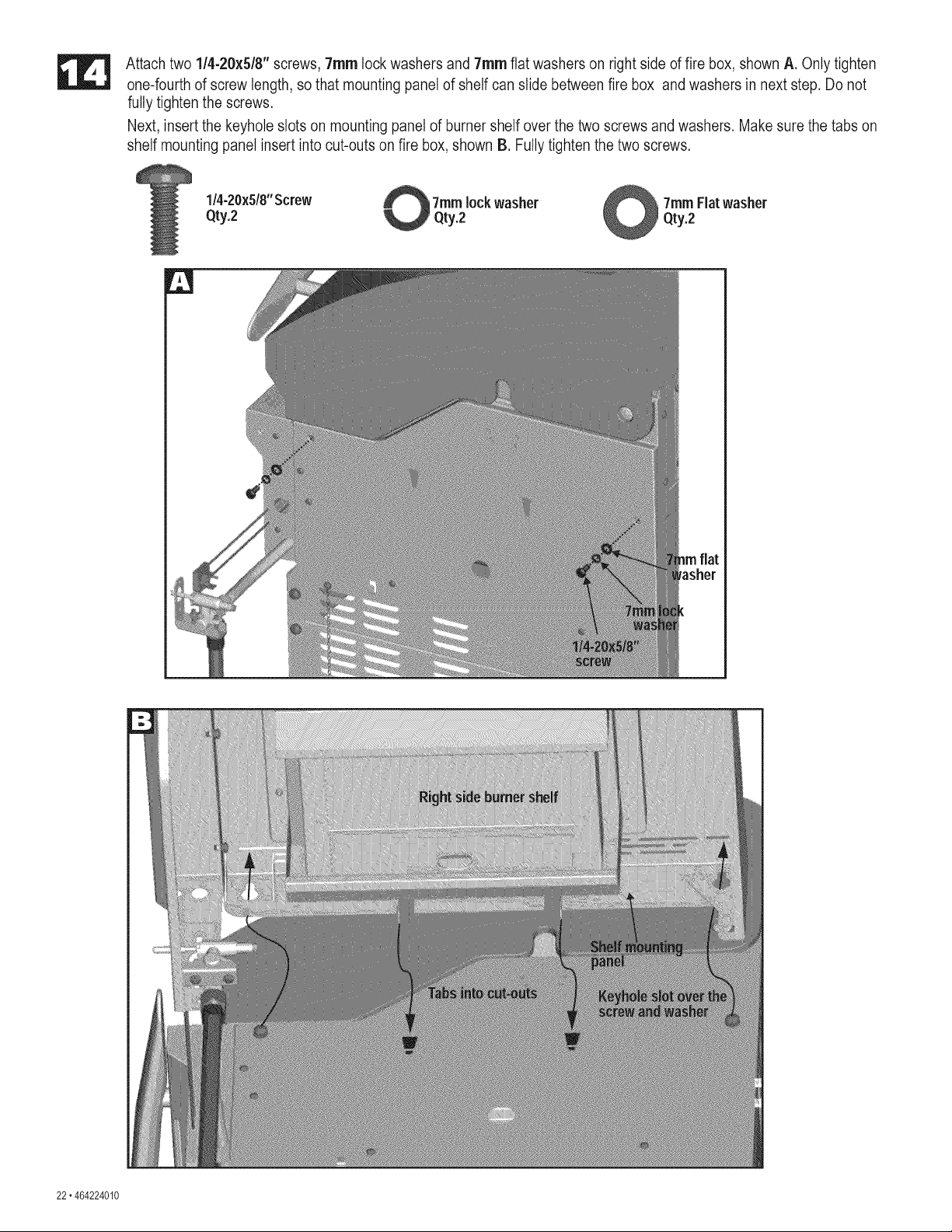
Attach two 1/4-20x5/8" screws, 7ram lock washers and 7ram flat washers on right side of fire box, shown A, Only tighten
one-fourth of screw length, so that mounting panel of shelf can slide between fire box and washers in next step. Do not
fully tighten the screws.
Next, insert the keyhole slots on mounting panel of burner shelf over the two screws and washers. Make sure the tabs on
shelf mounting panel insert into cut-outs on fire box, shown B. Fully tighten the two screws.
1/4.20x518"Screw lockwasher _ 7ram Fiatwasher
Qty.2 _ Qty.2
22.464224010
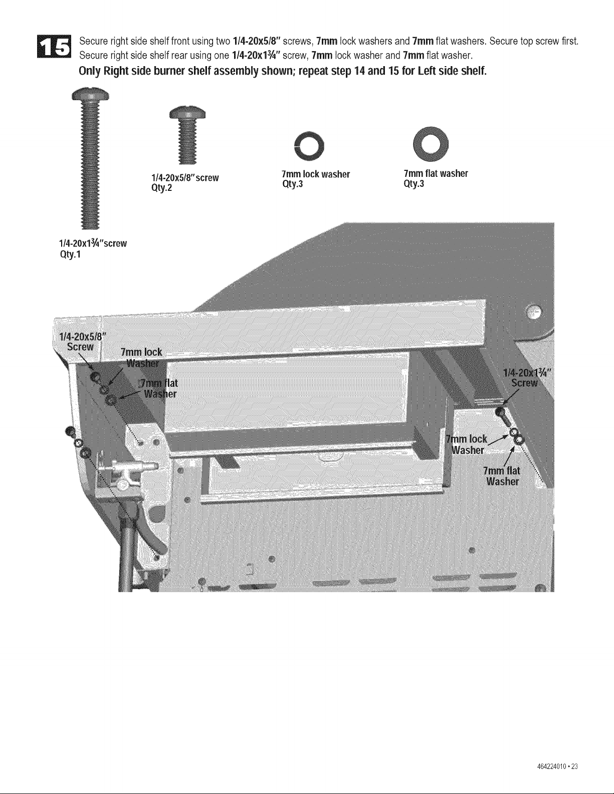
Secure right side shelf front using two 1/4-20x5/8" screws, 7ram lock washers and 7ram flat washers. Secure top screw first.
Secure right side shelf rear using one 1/4-20x13/_"screw, 7ram lock washer and 7ram flat washer.
Only Right side burner shelf assembly shown; repeat step 14 and 15 for Left side shelf.
1/4-20x5/8"screw 7rnmlockwasher
Qty.2 Qty.3
0
7ram flat washer
Qty.3
1/4-20x13A"screw
Qty.1
464224010.23
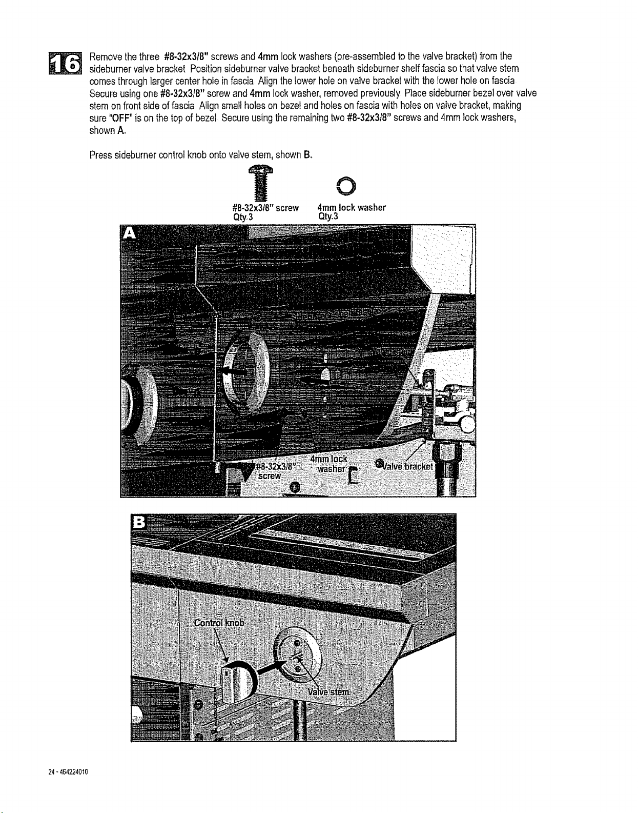
Removethe three #8.32x3f8" screwsand 4ram lock washers (pre-assembtedto the valvebracket)from the
sideburnervalvebracket Positionsideburnervatve bracketbeneath sideburnershelffascia so that valve stem
comes throughlarger center hole in fascia Align the lower hoie on valve bracketwith the lower holeon fascia
Secure usingone #8.32x3!8" screw and4ram lockwasher, removedpreviously Place sidebumer bezel over valve
stem on frontside of fascia Align small holes on bezel and holeson fascia with holes on vaivebracket,making
sure "OFF"is on the top of bezei Secureusing the remainingtwo #8-32x318"screwsand 4ram lock washers,
shownA,
Presssideburner control knob onto valve stem, shownB.
O
#8-32x3f8"screw 4mm lock washer
Q_3 Qty.3
24-464224010
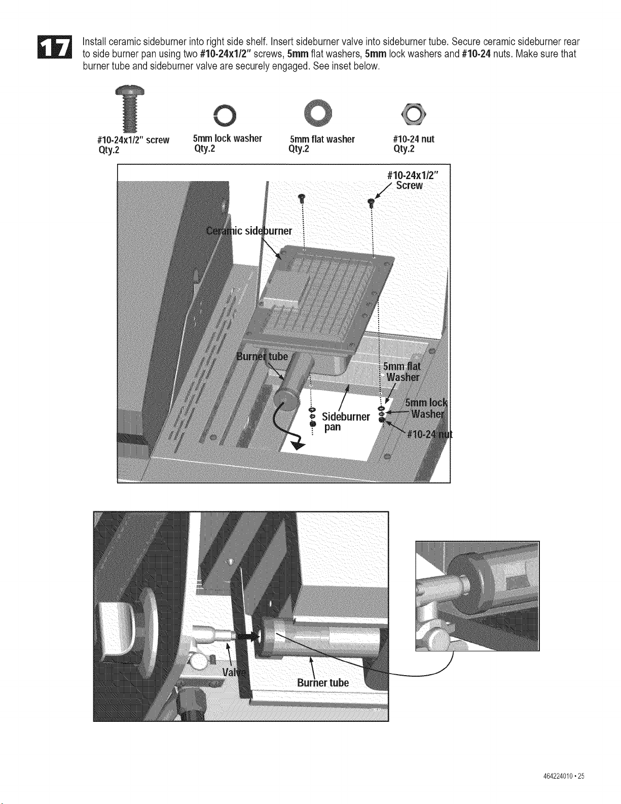
Install ceramic sideburner into right side shelf. Insert sideburner valve into sideburner tube. Secure ceramic sideburner rear
to side burner pan using two #10-24x1/2" screws, 5ram flat washers, 5ram lock washers and #10-24 nuts. Make sure that
burner tube and sideburner valve are securely engaged. See inset below.
#10-24xl/2" screw 5mmlock washer 5ramflat washer #10-24nut
Qty.2 Qty.2 Qty.2 Qty.2
I
#10-24x1/2"
Screw
T
464224010.25
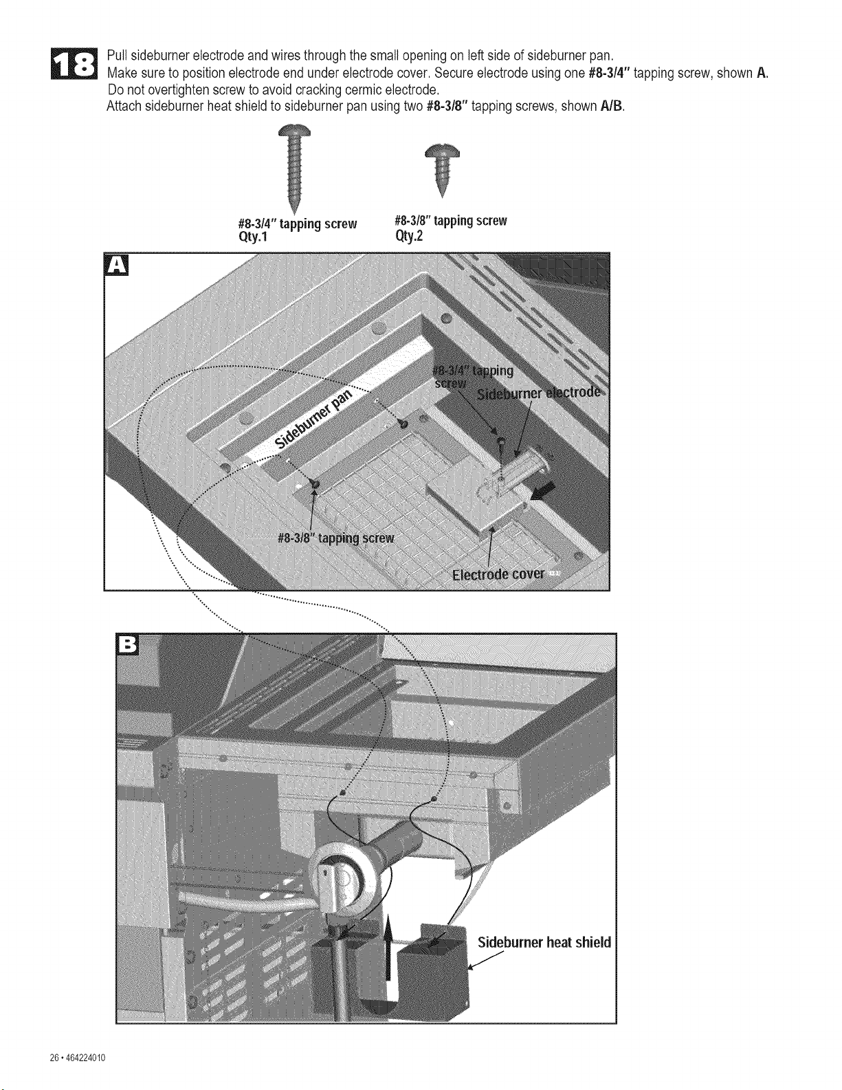
Pull sideburner electrode and wires through the small opening on left side of sideburner pan.
Make sure to position electrode end under electrode cover. Secure electrode using one #8-3/4" tapping screw, shown A.
Do not overtighten screw to avoid cracking cermic electrode.
Attach sidebumer heat shield to sideburner pan using two #8-3/8" tapping screws, shown A/B.
]'
#8-3/4" tapping screw #8-3/8"tapping screw
Qty.1 0ty.2
26.464224010
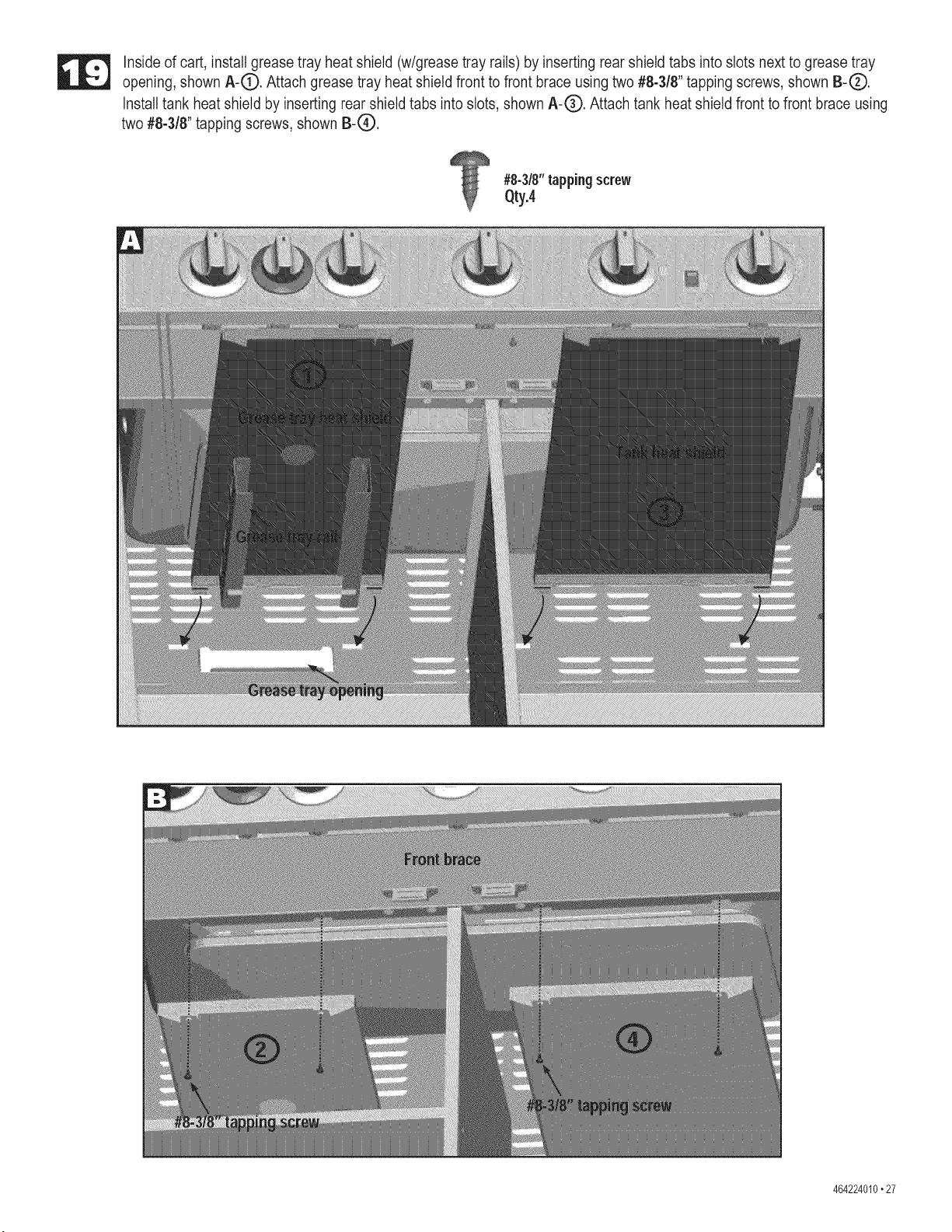
Inside of cart, install grease tray heat shield (w/grease tray rails) by inserting rear shield tabs into slots next to grease tray
opening, shown A-(D. Attach grease tray heat shield front to front brace using two #8-3/8" tapping screws, shown B-(_).
Install tank heat shield by inserting rear shield tabs into slots, shown A-O. Attach tank heat shield front to front brace using
two #8-3/8" tapping screws, shown B-O.
#8-3/8"tapping screw
Qty.4
464224010.27
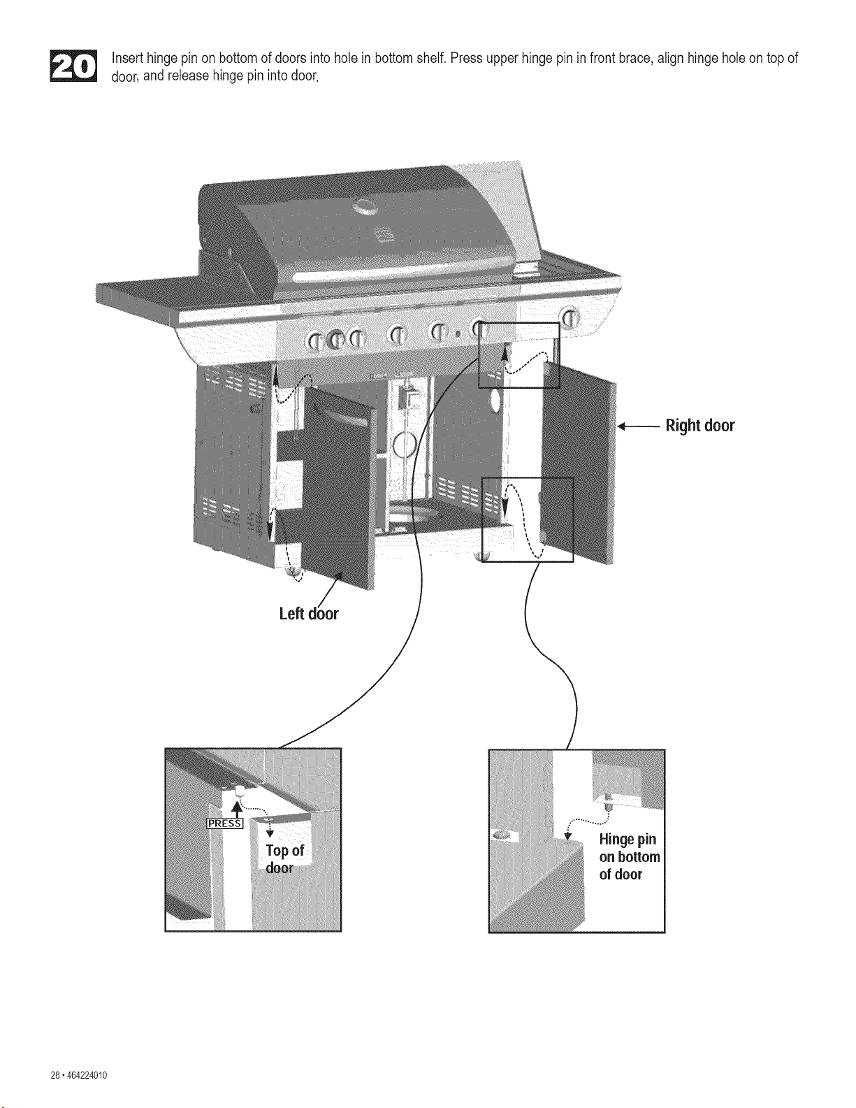
Insert hinge pin on bottom of doors into hole in bottom shelf. Press upper hinge pin in front brace, align hinge hole on top of
door, and release hinge pin into door.
Rightdoor
Hinge pin
on bottom
of door
28. 464224010
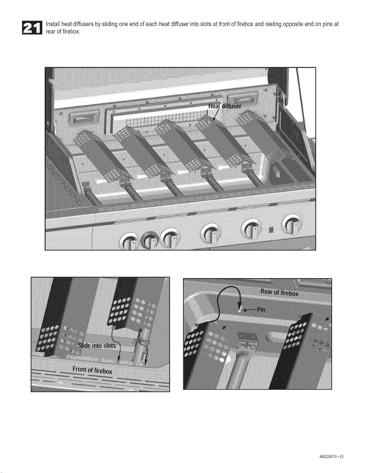
Install heat diffusers by sliding one end of each heat diffuser into slots at front of firebox and resting opposite end on pins at
rear of firebox.
464224010.29
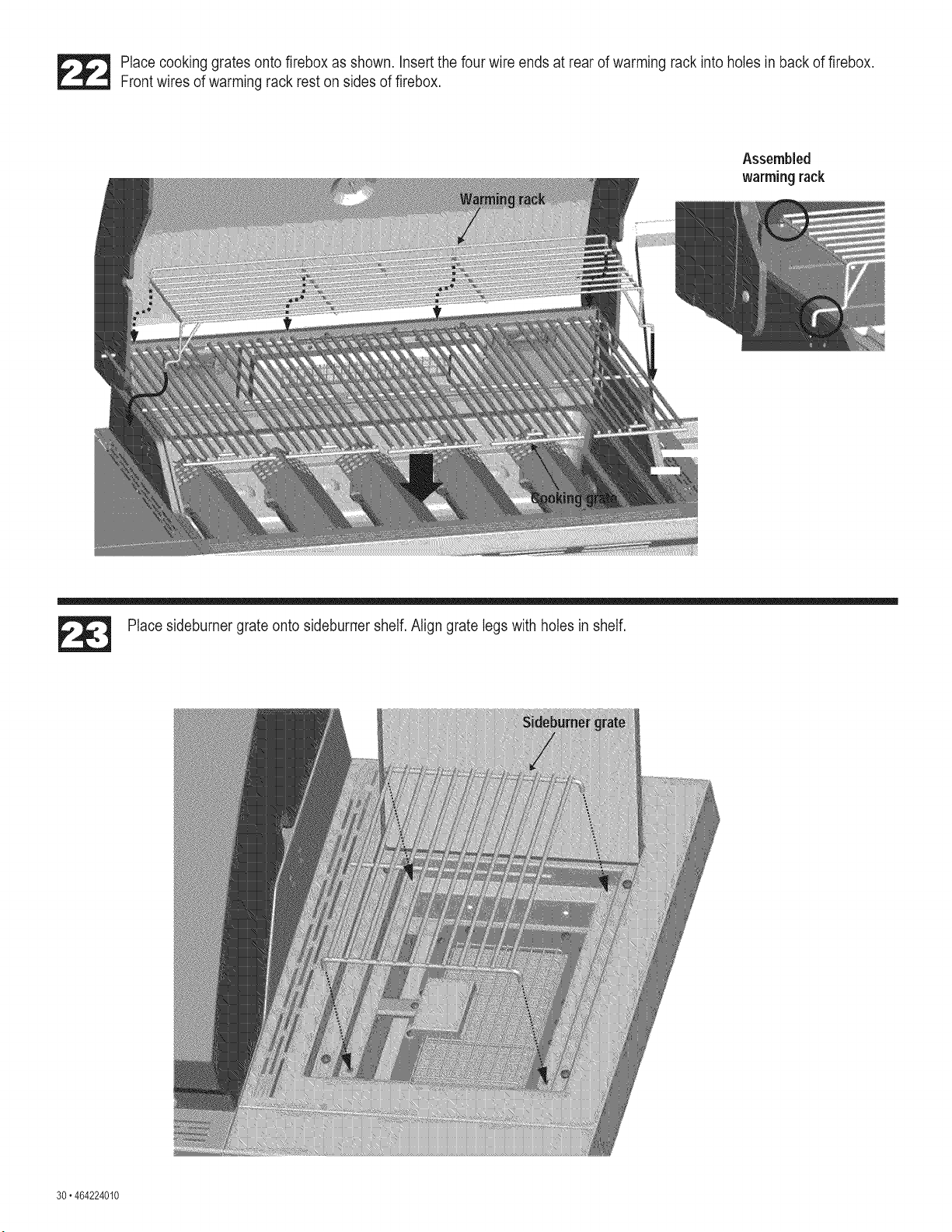
_ lace cooking grates onto firebox as shown. Insert the four wire ends at rear of warming rack into holes in back of firebox.
Frontwires of warming rack rest on sides of firebox.
Assembled
warming rack
Place sideburner grate onto sideburner shelf. Align grate legs with holes in shelf.
30.464224010
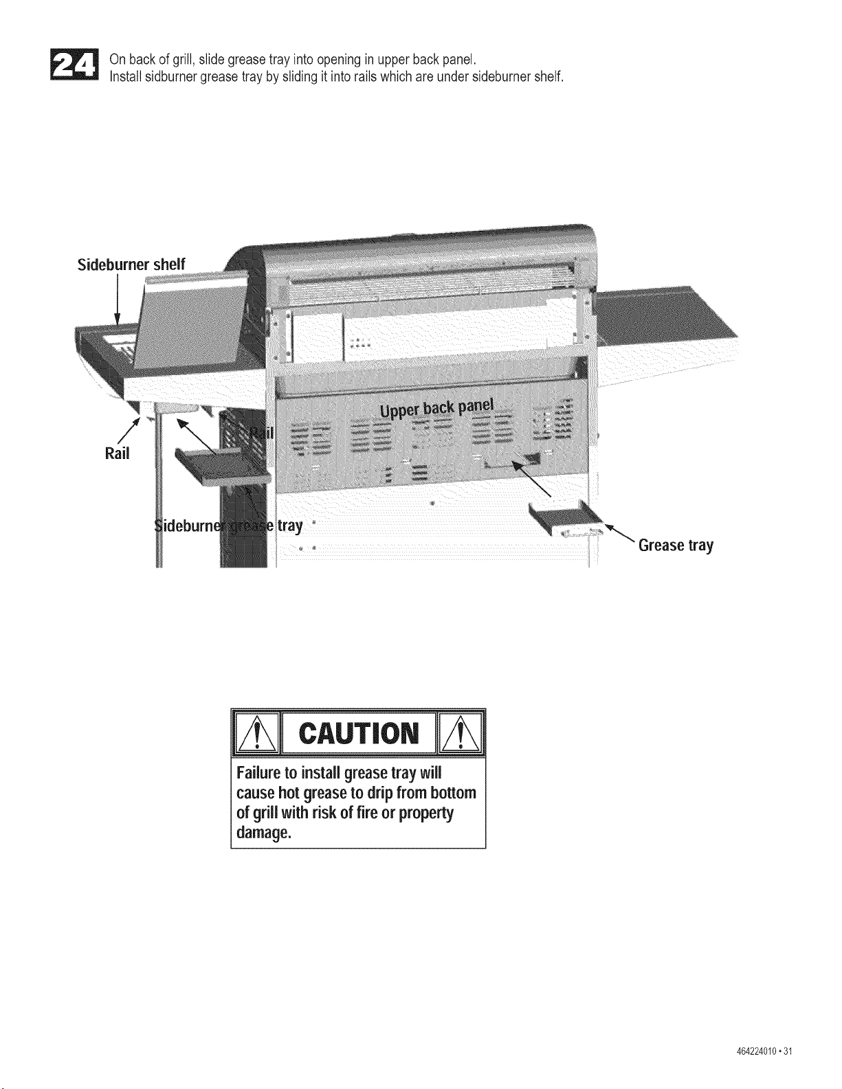
On back of grill, slide grease tray into opening in upper back panel.
Install sidburner grease tray by sliding it into rails which are under sideburner shelf.
Sideburner shelf
Grease tray
__ m
Failureto installgreasetray will
causehotgreaseto dripfrom bottom
of grillwithrisk of fire or property
damage.
464224010.31
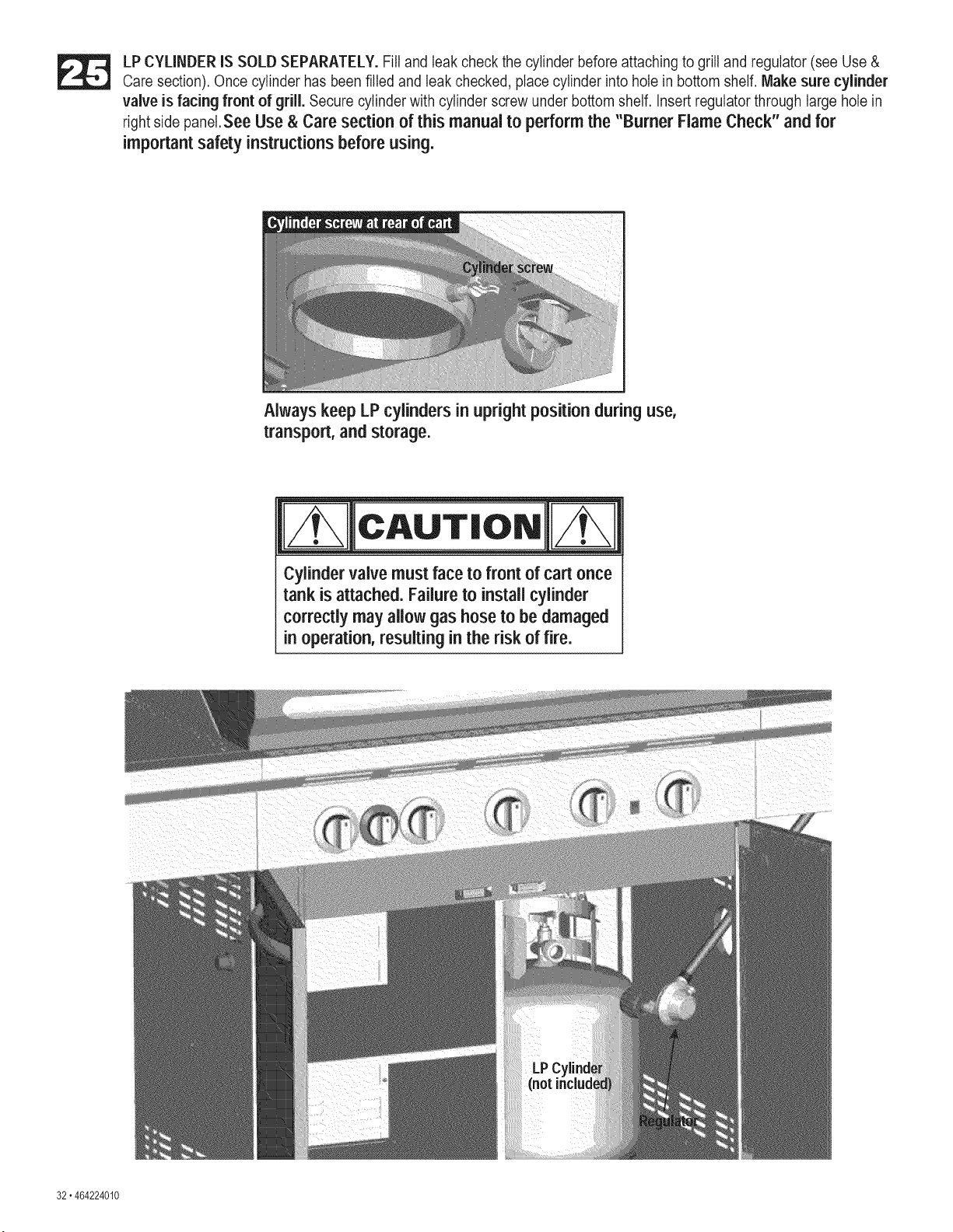
LP CYLINDER IS SOLD SEPARATELY. Fill and leak check the cylinder before attaching to grill and regulator (see Use &
Care section). Once cylinder has been filled and leak checked, place cylinder into hole in bottom shelf. Make sure cylinder
valve is facing front of grill. Secure cylinder with cylinder screw under bottom shelf. Insert regulator through large hole in
right side panel.See Use & Care section of this manual to perform the "Burner Flame Check" and for
important safety instructions before using.
Always keep LP cylinders in upright positionduring use,
transport, and storage.
CAUTION/
Cylinder valve must face to front of cart once
tank is attached. Failure to install cylinder
correctly may allow gas hose to be damaged
,n operation, resulting in the risk of fire.
32. 464224010
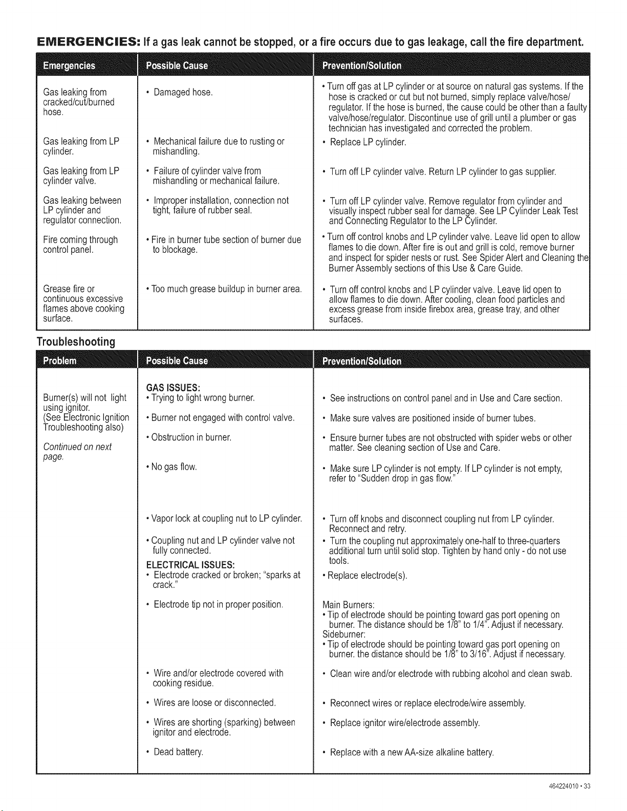
EMERGENCIES= If a gas leak cannot be stopped, or a fire occurs due to gas leakage, call the fire department.
Gasleakingfrom
cracked/cut/burned
hose.
Gasleakingfrom LP
cylinder.
Gasleakingfrom LP
cylindervalve.
Gasleakingbetween
LPcylinderand
regulatorconnection.
Firecomingthrough
controlpanel.
Greasefire or
continuousexcessive
flamesabovecooking
surface.
• Damagedhose.
, Mechanicalfailuredueto rustingor
mishandling.
, Failureof cylindervalvefrom
mishandlingormechanicalfailure.
, Improperinstallation,connectionnot
tight,failureof rubberseal.
, Firein burnertube sectionof burnerdue
to blockage.
, Toomuchgreasebuildupin burnerarea.
, Turnoffgas at LP cylinderor at sourceon naturalgassystems.If the
hoseis crackedorcut butnot burned,simplyreplacevalve/hose/
regulator.If the hoseis burned,the causecouldbe otherthana faulty
valve/hose/regulator.Discontinueuseof grilluntila plumberor gas
technicianhasinvestigatedandcorrectedtheproblem.
, ReplaceLPcylinder.
, Turnoff LPcylindervalve. ReturnLP cylinderto gassupplier.
, Turnoff LPcylindervalve. Removeregulatorfromcylinderand
visuallyinspectrubbersealfor damage.See LP CylinderLeakTest
andConnectingRegulatorto the LPCylinder.
, TurnoffcontrolknobsandLPcylindervalve.Leavelid opento allow
flamesto die down.After fireis out andgrillis cold,removeburner
and inspectfor spidernestsor rust.See SpiderAlertandCleaningthe
BurnerAssemblysectionsof this Use& CareGuide.
, Turnoff controlknobsandLPcylindervalve.Leavelid open to
allowflamesto diedown.Aftercooling,cleanfood particlesand
excessgreasefrominsidefireboxarea,greasetray,and other
surfaces.
Troubleshooting
Burner(s)will not light
usingignitor.
(SeeElectronicIgnition
Troubleshootingalso)
Continuedonnext
page.
GASISSUES:
•Tryingto lightwrongburner.
° Burnernot engagedwith controlvalve.
° Obstructioninburner.
• Nogas flow.
, Vaporlock at couplingnutto LPcylinder.
, Couplingnut andLPcylindervalve not
fullyconnected.
ELECTRICALISSUES:
, Electrodecrackedor broken;"sparksat
, Seeinstructionson controlpanelandin Use and Caresection.
, Makesurevalvesare positionedinsideof burnertubes.
, Ensureburnertubesare notobstructedwithspiderwebsor other
matter.Seecleaningsectionof UseandCare.
, Makesure LPcylinderis notempty.If LPcylinderis not empty,
referto "Suddendropin gasflow."
, Turnoff knobsanddisconnectcouplingnut fromLPcylinder.
Reconnectandretry.
, Turnthe couplingnut approximatelyone-halfto three-quarters
additionalturn untilsolidstop.Tightenby handonly- do not use
tools.
, Replaceelectrode(s).
crack."
, Electrodetip notin properposition.
, Wireand/orelectrodecoveredwith
cookingresidue.
, Wiresarelooseor disconnected.
, Wiresareshorting(sparking)between
ignitorand electrode.
, Deadbattery.
MainBurners:
, Tip of electrodeshouldbepointingtowardgasport openingon
burner.The distanceshouldbe 118"to 114".Adjustif necessary.
Sideburner:
, Tip of electrodeshouldbepointingtowardgasport openingon
burner,the distanceshouldbe 118"to 3116".Adjust if necessary.
, Cleanwire and/orelectrodewithrubbingalcoholandcleanswab.
, Reconnectwiresorreplaceelectrode/wireassembly.
, Replaceignitorwire/electrodeassembly.
, Replacewitha newAA-sizealkalinebattery.
464224010" 33
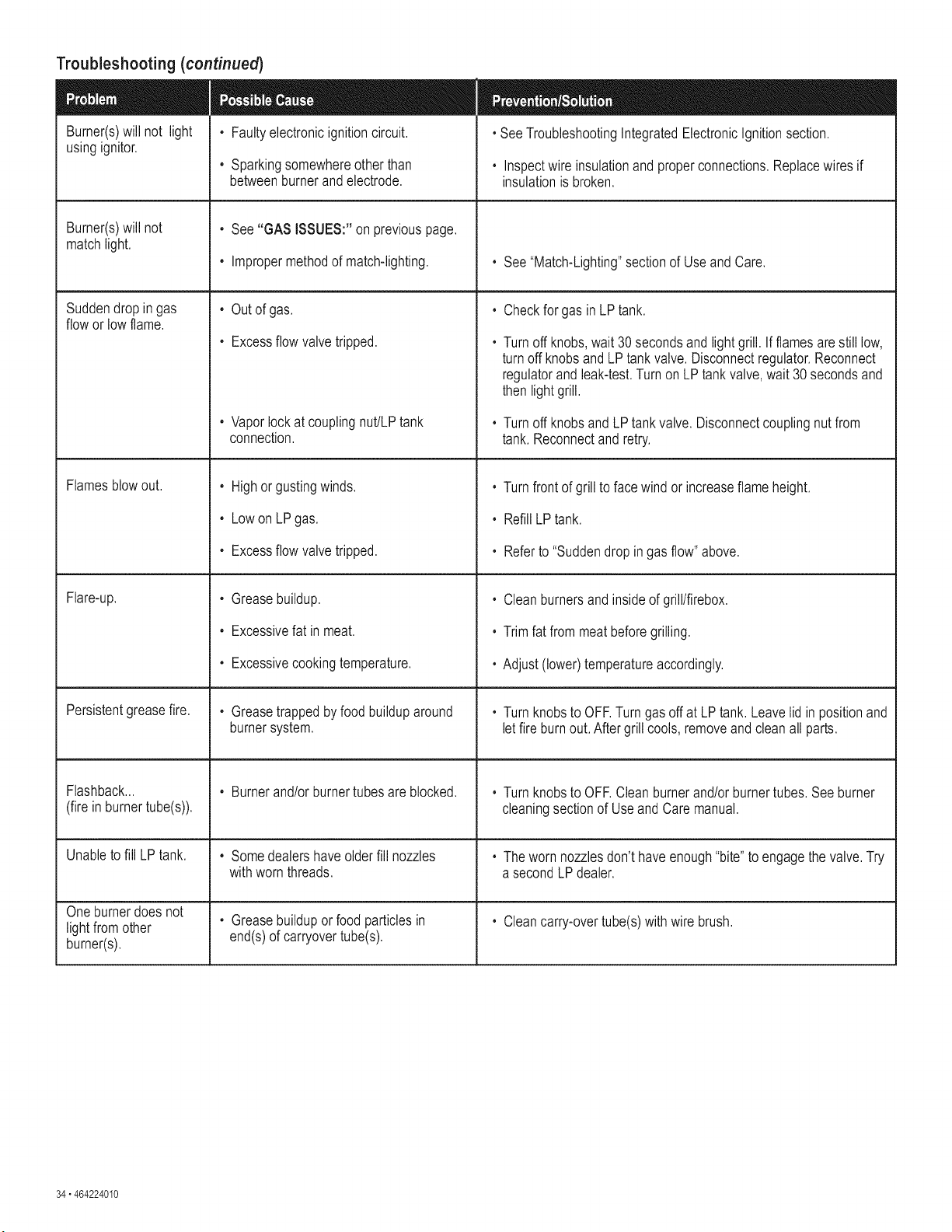
Troubleshooting(continued)
• Faultyelectronicignitioncircuit.
Burner(s)will not light
usingignitor.
Burner(s)will not
matchlight.
Suddendropingas
flowor lowflame.
Flamesblowout.
Flare-up.
Persistentgreasefire.
Flashback...
(fire in burnertube(s)).
Unableto fill LPtank.
Oneburnerdoesnot
light fromother
burner(s).
• Sparkingsomewhereotherthan
betweenburnerandelectrode.
• See"GAS ISSUES:"on previouspage.
• Impropermethodof match-lighting.
, Outof gas.
• Excessflowvalvetripped.
• Vaporlockat couplingnut/LPtank
connection.
, Highor gustingwinds.
, LowonLP gas.
• Excessflowvalvetripped.
, Greasebuildup.
• Excessivefat in meat.
• Excessivecookingtemperature.
• Greasetrappedbyfood builduparound
burnersystem.
• Burnerand/orburnertubesareblocked.
• Somedealershaveolderfill nozzles
withwornthreads.
• Greasebuildupor foodparticlesin
end(s)of carryovertube(s).
• SeeTroubleshootingIntegratedElectronicIgnitionsection.
• Inspectwire insulationand properconnections.Replacewires if
insulationis broken.
• See"Match-Lighting"sectionof UseandCare.
• Checkfor gas in LPtank.
• Turnoff knobs,wait 30secondsandlightgrill. If flamesarestill low,
turnoffknobsandLPtankvalve.Disconnectregulator.Reconnect
regulatorand leak-test.Turnon LP tank valve,wait 30 secondsand
thenlightgrill.
• Turnoff knobsandLPtankvalve. Disconnectcouplingnutfrom
tank.Reconnectandretry.
• Turnfrontof grillto facewindor increaseflameheight.
• RefillLPtank.
• Referto "Suddendropin gas flow"above.
, Cleanburnersandinsideof grill/firebox.
• Trimfat from meatbeforegrilling.
• Adjust(lower)temperatureaccordingly.
, Turnknobsto OFF.Turngas off at LPtank. Leavelid in positionand
letfire burn out.After grill cools,removeandcleanall parts.
• Turnknobsto OFF.Cleanburnerand/orburnertubes.Seeburner
cleaningsectionof Useand Caremanual.
• Theworn nozzlesdon'thaveenough"bite"to engagethe valve.Try
asecondLPdealer.
• Cleancarry-overtube(s)withwire brush.
34" 464224010

Troubleshooting- integrated Electronic ignition
• Batterynot installed
properly.
SECTIONI
Nosparksappearat
any electrodeswhen
burnercontrolknobs
areturnedto_ •no
noisecan be heard
fromsparkmodule.
• Deadbattery.
SECTION II
No sparks appear at
any electrodes when
burner control knobs
are turned to_; noise
can be heard from
spark module.
SECTION ill
Sparks are present
but not at all
electrodes and/or not
at full strength
• Check battery orientation. • Installbattery(makesurethat"+" and "-"
connectorsareorientedcorrectly,with"+" endup
, Hasbatterybeenused
previously?
and"-" enddown.)
, ReplacebatterywithnewAA-sizealkalinebattery.
, Batterycap not
installedproperly.
, Faultysparkmodule.
, Outputlead
connectionsnot
connected.
, Electrodetip not in
properposition.
, Outputlead
connectionsnot
connected.
, Arcingto grill away
fromburner(s).
, Weakbattery.
, Electrodesare wet.
, Electrodescrackedor
broken"sparksat
crack".
, Checkto ensurebatterycap
is fully engaged.
, If no sparksaregenerated
withnewbatteryandgood
wireconnections,moduleis
faulty.
, Areoutputconnectionson
andtight?
, Arethe electrodetips
pointingin the right
direction?Isthe gap too big?
, Areoutputconnectionson
andtight?
, If possible,observegrillin
darklocation.Operate
ignitionsystemand lookfor
arcingbetweenoutputwires
andgrillframe.
, All sparkspresentbutweak
orat slowrate.
, Hasmoistureaccumulated
onelectrodeand/orin burner
ports?
, Inspectelectrodesfor
cracks.
, Removebatterycap and reinstall,makingsure it
can be fully engaged.
, Replacesparkmoduleassembly.
, Removeandreconnectalloutputconnectionsat
moduleand electrodes.
MainBurners:
, Tipof electrodeshouldbepointingtowardport hole
in burner.The distanceshouldbe 1/8"to 3t16".
Adjustif necessary.
Sideburner:
, Tipof electrodeshouldbepointingtowardgas port
openingon burner.Thedistanceshouldbe 1/8"to
3t16".Adjustif necessary.
, Removeandreconnectalloutputconnectionsat
moduleand electrodes.
• If sparksare observedotherthan from burner(s),
wire insulationmaybe damaged.Replacewires.
, Replacebatterywitha newAA-sizealkalinebattery.
, Usepapertowelto removemoisture.
, Replacecrackedor brokenelectrodes.
464224010 • 35
Your Home
Forexperttroubleshooting and homesolutionsadvice:
aHage
For repair- in your home - of all major brand appliances,
lawn and garden equipment, orheating and cooling systems,
no matterwho madeit, no matterwhosold it!
Forthereplacementparts, accessoriesand
owner's manualsthatyou need todo-it-yourself.
For Sears professional installation of home appliances
and items like garage door openers and water heaters.
i8i8i8i8i8i_i
i8i8i8i8i8i_i
i8i8i8i8i8i_i
i8i8i8i8i8i_i
i8i8i8i8i8i_i
i8i8i8i8i8i_i
i8i8i8i8i8i_i
i8i8i8i8i8i_i
i8i8i8i8i8i_i
i8i8i8i8i8i_i
i8i8i8i8i8i_i
i8i8i8i8i8i_i
i8i8i8i8i8i_i
i8i8i8i8i8i_i
i8i8i8i8i8i_i
i8i8i8i8i8i_i
i8i8i8i8i8i_i
i8i8i8i8i8i_i
i8i8i8i8i8i_i
i8i8i8i8i8i_i
i8i8i8i8i8i_i
i8i8i8i8i8i_i
i8i8i8i8i8i_i
i8i8i8i8i8i_i
i8i8i8i8i8i_i
1-800-4-MY-HOME ® (1-8oo-46e-466s)
iiiiiiiiiiiiiiiiiiii_
Call anytime, day or night (U.S.A. and Canada)
Our Home
For repair of carry-in items like vacuums, lawn equipment,
and electronics, call anytime for the location of your nearest
Sears Parts & Repair Service Center
1-800-488-1222 (U.S.A.) 1-800-469-4663 (Canada)
www.sears.com www.sears.ca
SM
® Registered Trademark / TMTrademark / Service Mark of Sears Brands, LLC
TM
® Marca Registrada / Marca de Fabrics / SM Marca de Servicio de Sears Brands, LLC
MC Marque de commerce / MD Marque deposde de Sears Brands, LLC ® Sears Brands, LLC