Loading ...
Loading ...
Loading ...
Section 2 -OPERATING INSTRUCTIONS
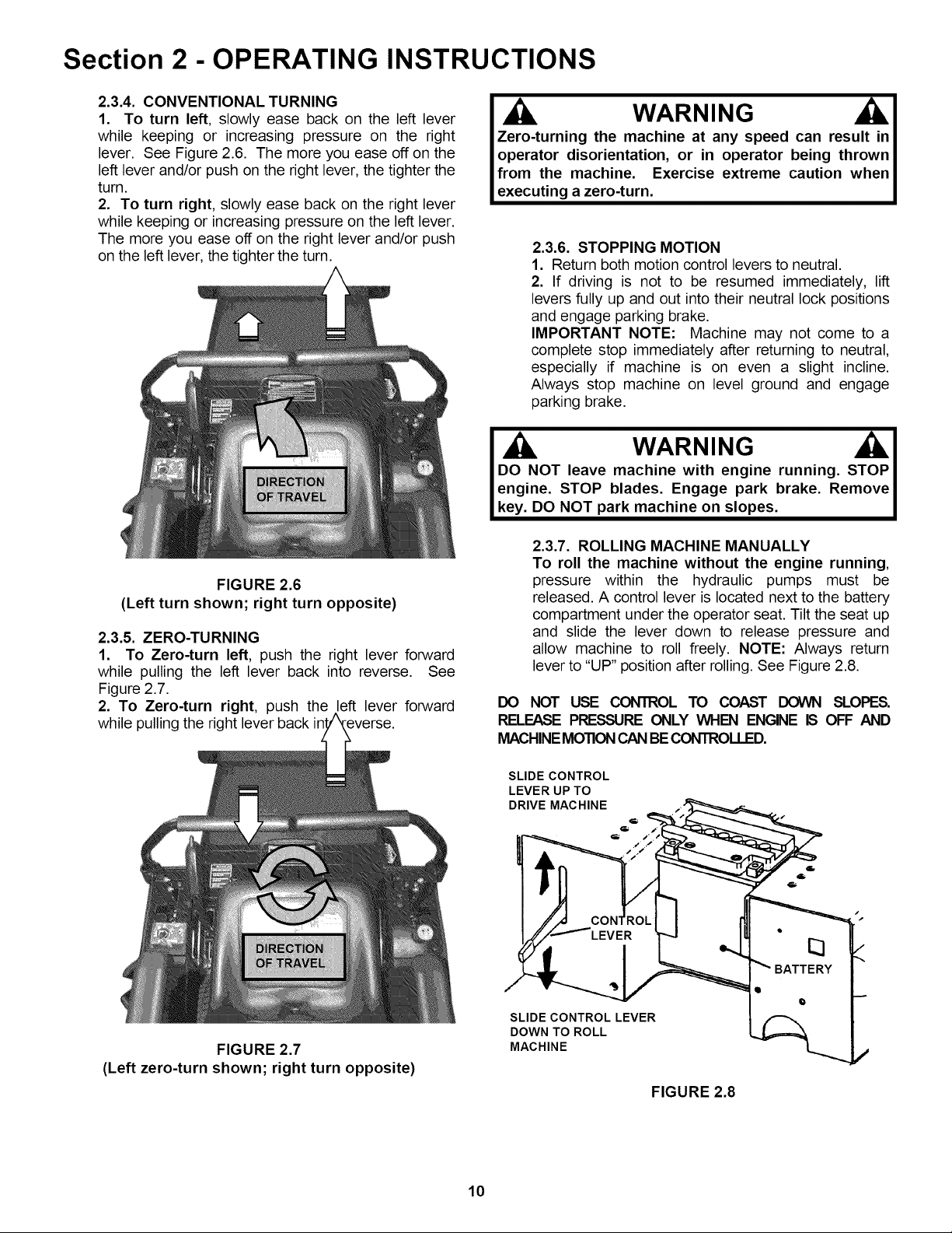
2.3.4. CONVENTIONAL TURNING
1. To turn left, slowly ease back on the left lever
while keeping or increasing pressure on the right
lever. See Figure 2.6. The more you ease off on the
left lever and/or push on the right lever, the tighter the
turn.
2. To turn right, slowly ease back on the right lever
while keeping or increasing pressure on the left lever.
The more you ease off on the right lever and/or push
on the left lever, the tighter the turn.
FIGURE 2.6
(Left turn shown; right turn opposite)
2.3.5. ZERO-TURNING
1. To Zero-turn left, push the right lever forward
while pulling the left lever back into reverse. See
Figure 2.7.
2. To Zero-turn right, push the left lever forward
while pulling the right lever back
WARNING h,J
Zero-turning the machine at any speed can result in
operator disorientation, or in operator being thrown
from the machine. Exercise extreme caution when
executing a zero-turn.
2.3.6. STOPPING MOTION
1. Return both motion control levers to neutral.
2. If driving is not to be resumed immediately, lift
levers fully up and out into their neutral lock positions
and engage parking brake.
IMPORTANT NOTE: Machine may not come to a
complete stop immediately after returning to neutral,
especially if machine is on even a slight incline.
Always stop machine on level ground and engage
parking brake.
WARNING
DO NOT leave machine with engine running, STOP
engine, STOP blades, Engage park brake, Remove
key, DO NOT park machine on slopes,
2.3.7. ROLLING MACHINE MANUALLY
To roll the machine without the engine running,
pressure within the hydraulic pumps must be
released. A control lever is located next to the battery
compartment under the operator seat. Tilt the seat up
and slide the lever down to release pressure and
allow machine to roll freely. NOTE: Always return
lever to "UP" position after rolling. See Figure 2.8.
DO NOT USE CONTROL TO COAST DOWN SLOPES.
RELEASE PRESSURE ONLY WHEN ENGINE IS OFF AND
MACHINEMOTIONCANBE CONTROLLED.
FIGURE 2.7
(Left zero-turn shown; right turn opposite)
SLIDE CONTROL
LEVER UP TO
DRIVE MACHINE _ _'_=_--=.,_,_ .._.- _ -_.=
_ f
LJI. I _ BATTERY "
SLIDE CONTROL LEVER
DOWN TO ROLL
MACHINE /
FIGURE 2.8
10
Loading ...
Loading ...
Loading ...