Loading ...
Loading ...
Loading ...
EZ-LINK SYSTEM DUAL INSTALLATION
62
EZ-LINK CABLE CONNECTION
The references in steps 5 to 8 are to the
‘Control Board with Ez-Link Connection’ diagram on page 63. To
connect the Ez-Link cable to the water heaters:
1. Close any hot taps and ensure the burners on both water heaters are not operating.
2. Switch off the electrical supply at the power outlet to each water heater.
3. Remove the screws holding the front panel to the jacket on each water heater.
4. Gently disengage the front panel and pull forward to remove from each water heater.
5. Connect one end of the EZ-Link cable to the first water heater.
Draw the cable through the cable grommet on the underside of the water heater.
Plug the cable into the connector marked “E” in the upper right-hand corner of the Control Board
(refer to the Control Board diagram).
The connector will only fit one way.
Press until the connector snaps into place.
Secure the EZ-Link cable with the clamp and screw provided to the bottom right of the Control
Board (refer to the
Control Board diagram).
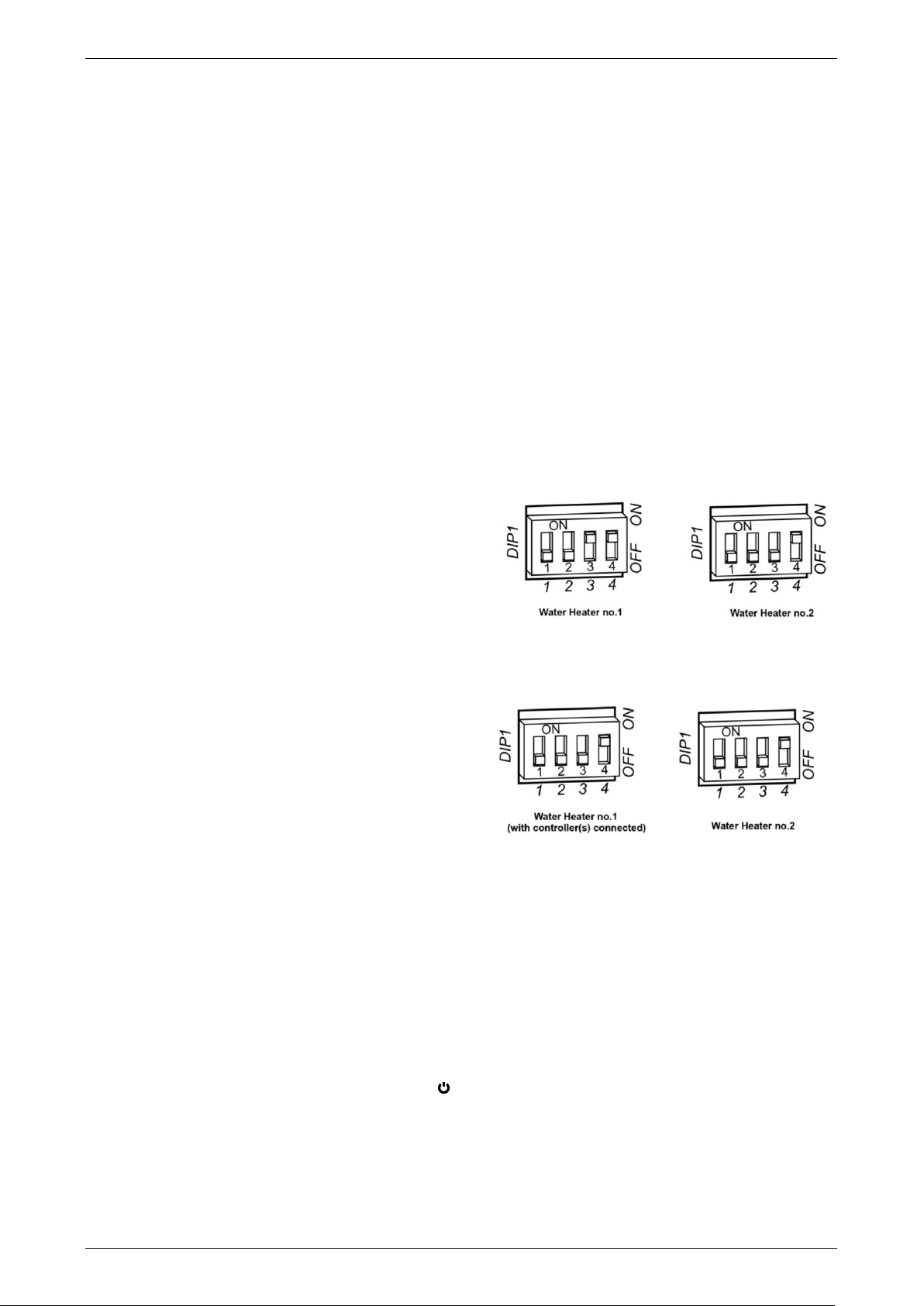
6. Switch DIP SWITCH 4 to the on (up) position on
the first water heater (refer to the
Control Board
diagram).
If a temperature controller is not installed, then
also switch DIP SWITCH 3 to the on (up)
position on the first water heater.
7. Connect the other end of the EZ-Link cable to the
second water heater.
Draw the cable through the cable grommet on
the underside of the water heater.
Plug the cable into the connector marked “E” in
the upper right-hand corner of the Control
Board (refer to the
Control Board diagram).
The connector will only fit one way.
Press until the connector snaps into place.
Secure the EZ-Link cable with the clamp and
screw provided to the bottom right of the
Control Board (refer to the Control Board
diagram).
8. Switch DIP SWITCH 4 to the on (up) position on the second water heater (refer to the
Control Board
diagram).
9. Refit the front panel and screws to each water heater.
10. Check the main gas isolation valve and the isolation valves at the gas inlet to each water heater are fully
open.
11. Switch on the electrical supply at the power outlet to the water heater.
12. Turn on the controller by pressing the on / off ( ) button, if one is installed.
The on / off operating light and the priority light will both glow.
dip switch settings
without temperature controller
dip switch settings
with temperature controller connected
Loading ...
Loading ...
Loading ...