Loading ...
Loading ...
Loading ...
EZ-LINK SYSTEM DUAL INSTALLATION
61
DUAL INSTALLATION
The two continuous flow water heaters can be installed side by side with minimal clearance between them.
The AGA has approved the installation of two of this model water heater with an exemption from the 300 mm
minimum clearance requirements between flue terminals, as stated in AS/NZS 5601, clause 5.13.6.5 and
AS/NZS 5601.1, clause 6.9.3.
Install two continuous flow water heaters of the same model in a parallel plumbing arrangement. It is good
practice, but not essential, to install the two water heaters in an Equa-Flow
®
manifold plumbing arrangement.
There are basic installation requirements which must be followed:
1. The pipe work must be sized to meet the requirements of both AS/NZS 3500.4 and the application. It is
recommended to use minimum DN25 pipe for the cold water line, cold and hot headers and hot water
line and DN20 for the cold and hot water branch lines of each water heater.
2. A full flow gate valve or ball valve must be installed on the cold water line to the system. A non-return
valve or stop tap must not be installed.
3. A full flow gate valve or ball valve (not a stop tap) should be installed on both the cold water branch and
hot water branch of each water heater.
4. An isolation valve must be installed on the gas branch of each water heater.
5. Non-return valves or pressure limiting valves must not be installed on the branch lines to the water
heaters.
6. All fittings, valves and branch lines should be matched sets to each of the water heaters.
7. Sufficient space must be left to enable access, servicing or removal of either water heater.
Refer to the
‘Typical Two Unit Manifold with Ez-Link Connection’ diagram on page 64 for installation and
plant layout details.
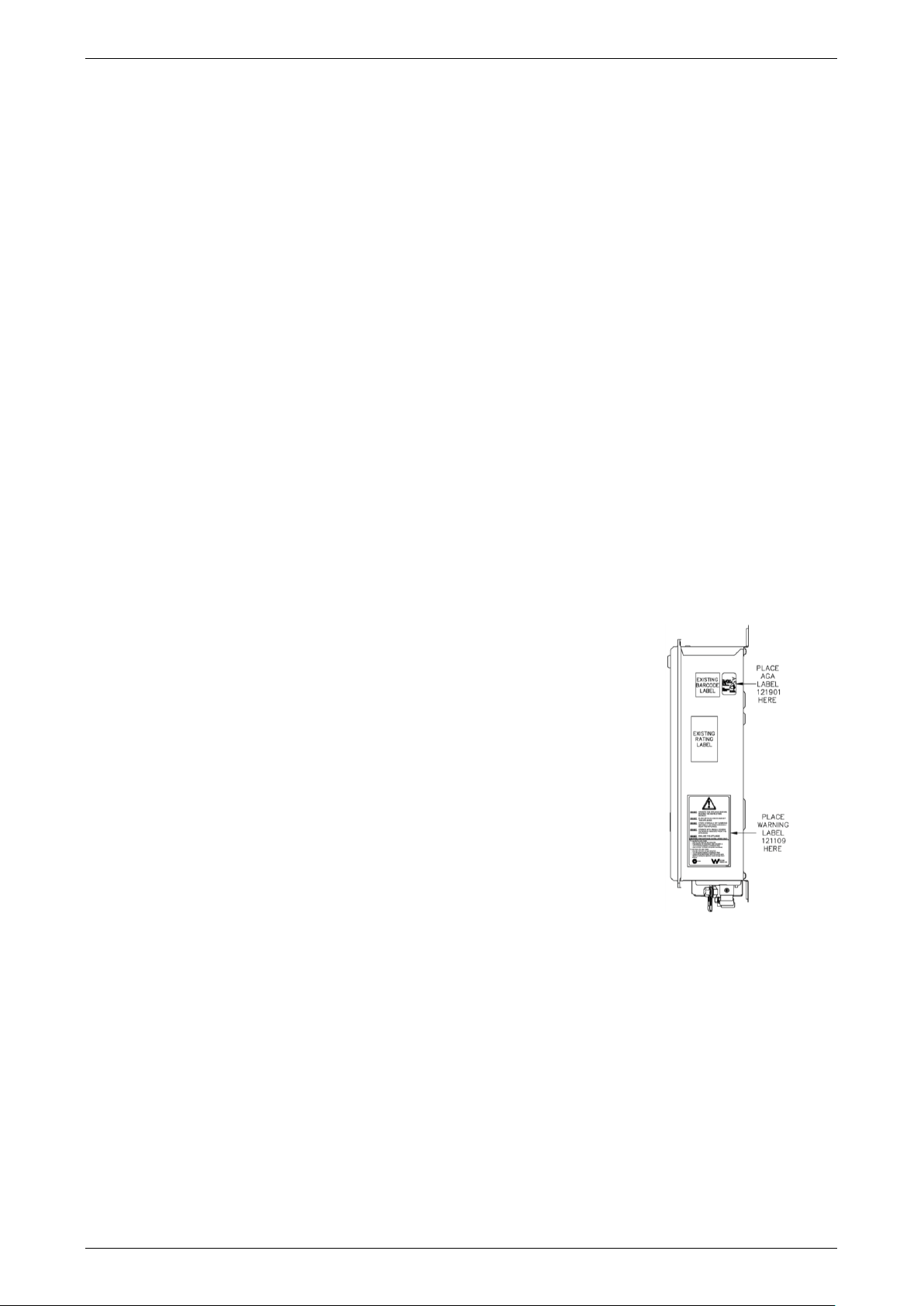
LABELS
A warning label (121109) and an AGA approval label (121901) are
supplied in the Ez-Link kit. Where the two water heaters are installed close
together and the warning label and AGA approval label on the inside face
of the right hand water heater cannot be read, it is necessary to adhere the
two labels supplied to the right-hand face of the water heater.
1. Place the warning label below the rating label.
2. Place the AGA approval label beside the barcode label.
Refer to the
‘Label Positioning’ diagram on page 61 for the position of the
two labels to be adhered to the water heater.
A second rating label is attached to the inside of the front cover. This can
be referenced to determine details of the left hand water heater.
TEMPERATURE CONTROLLER
A temperature controller may be installed with the EZ-Link system. The controller can be either a standard or
Deluxe controller. Rheem 874 and 876 series 612, 616, E16, 618 and 620 model water heaters do not
require a temperature controller to be installed as part of an Ez-link system installation.
Connect a temperature controller to one only of the two water heaters. Up to three temperature controllers of
the same family can be installed to this water heater. Refer to
“Installation – Controllers” on page 65.
The water heater connected with the temperature controller(s) will become the “master” water heater. The
installed temperature controller(s) will control the temperature and functionality of both water heaters. The
maximum outlet temperature of the water heaters will be limited by the maximum temperature setting of the
temperature controller.
A temperature controller should not be installed if two 874 series 612, 616, E16, 618 or 620 model water
heaters have been Ez-Linked together and they are part of a circulated hot water flow and return system in a
building. Refer to
“Circulated Hot Water Flow And Return System” on page 51.
Label Positioning
Loading ...
Loading ...
Loading ...