1
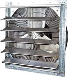
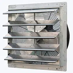
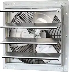
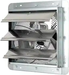
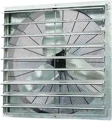
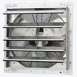
SHUTTER MOUNTED EXHAUST FAN
Models: ILG8SF7V/ILG8SF10V/ILG8SF12V/ILG8SF16V
ILG8SF18V/ILG8SF18S/ILG8SF20V/ILG8SF24V
ILG8SF30S/ILG8SF36S
OWNER'S MANUAL
PLEASE READ AND SAVE THESE
INSTRUCTIONS
2
PLEASE READ AND SAVE THESE INSTRUCTIONS. READ CAREFULLY BEFORE
ATTEMPTING TO ASSEMBLE, INSTALL, OPERATE, OR MAINTAIN THE PRODUCT
DESCRIBED. PROTECT YOURSELF AND OTHERS BY OBSERVING ALL SAFETY
INFORMATION. FAILURE TO COMPLY WITH INSTRUCTIONS COULD RESULT IN
PERSONAL INJURY AND/OR PROPERTY DAMAGE! RETAIN INSTRUCTIONS FOR
FUTURE REFERENCE.
BEFORE YOU BEGIN
WARNING!
Installation, trouble shooting, and replacement of parts are to be performed
only by authorized service technicians.
Electrical Requirements:
• The motor amperage and voltage ratings must be checked for
compatibility to supply voltage prior to final electrical connection. Please
refer to the motor's nameplate label.
• Wiring must conform to local, state, and national codes.
Tools / Materials Needed:
• Mounting Fasteners (8)
• Sealant or Caulk
• Regular Screwdriver Set
UNPACKING
Contents:
• Shutter Mounted Exhaust Fan
• Owner’s Manual
Inspect:
• After unpacking fan, carefully inspect for any damage that may have
occurred during transit. Check for loose, missing, or damaged parts.
• Check all bolts, screws, set-screws, etc. for looseness that may have
occurred during transit. Tighten as needed. Rotate propeller by hand to
ensure it turns freely.
• See General Safety Instructions on page 3, and Cautions and Warnings
as shown.

3
Fans are UL/CUL Listed.
1. Do not depend on any switch as the sole means of disconnecting
power when installing or servicing the fan.
2. Always disconnect, lock-out, and tag-out power source before installing
or servicing. Failure to disconnect power source can result in fire, shock,
or serious injury.
3. Motor will restart without warning after thermal protector trips. Do not
touch operating motor; it may be hot enough to cause injury.
4. Do not place body parts or objects in fan or motor openings while motor
is connected to the power source.
5. All electrical connections should be made by a qualified electrician.
6. These utility exhaust fans are for general purpose exhaust applications
only. Do not use these exhaust fans in an area where corrosive or
explosive materials may be found.
7. Follow all local and state/provincial electrical and safety codes in the
United States and Canada, as well as the National Electrical Code (NEC)
and the Occupational Safety and Health Act (OSHA) in the United States,
and the Canadian Electric Code (CEC) in Canada.
8. Always disconnect power source before working on or near a motor or its
connected load.
9. Protect the power cable from coming in contact with sharp objects.
10. Do not kink or create tight bends in the power cable and never allow the
cable to come in contact with oil, grease, hot surfaces, or chemicals.
11. Make certain that the power source conforms to the requirements of
your specific exhaust fan model. The fan frame and motor must be
electrically grounded to a suitable electrical ground, such as a grounded
water pipe or ground wire system.
12. To reduce the risk of injury to persons, please observe the following:
In the United States, OSHA compliant guards are required when fan is
installed within 7 feet of the floor or working level. In Canada, CSA
compliant guards are required when fan is installed below 2.5 meters
(8.2 feet) above the floor or grade level.
13. Questions? Please contact our service center by calling 1-800-317-
1688.
WARNING – To Reduce The Risk Of Electric Shock, This Fan Must Be
Installed With An Isolating Wall Control/Switch.
GENERAL SAFETY INSTRUCTIONS
4
INSTALLATION INSTRUCTION
1. The unit should be securely mounted in a rigid framework.
NOTE: Allowing the fan frame to flex or move will result in excess
vibrations, which may cause possible premature motor, propeller, or
shutter failure.
2. Install any auxiliary components such as thermostats, switches, or speed
controls.
3. Connect power to the motor using an approved wiring method.
Refer to the following wiring diagrams.
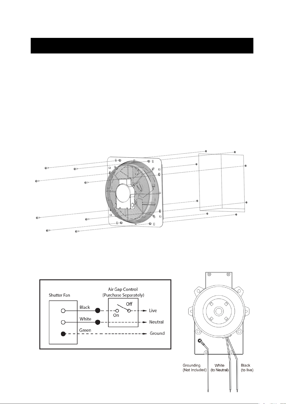
4. Install the shutter fan through 8 holes with screws. (Screws are not
included.) Please refer to page 7 for detailed dimensions.
5. Follow all local electrical and safety codes. Connect wires as shown
in wiring diagrams.
INSTALLATION INSTRUCTIONS
5
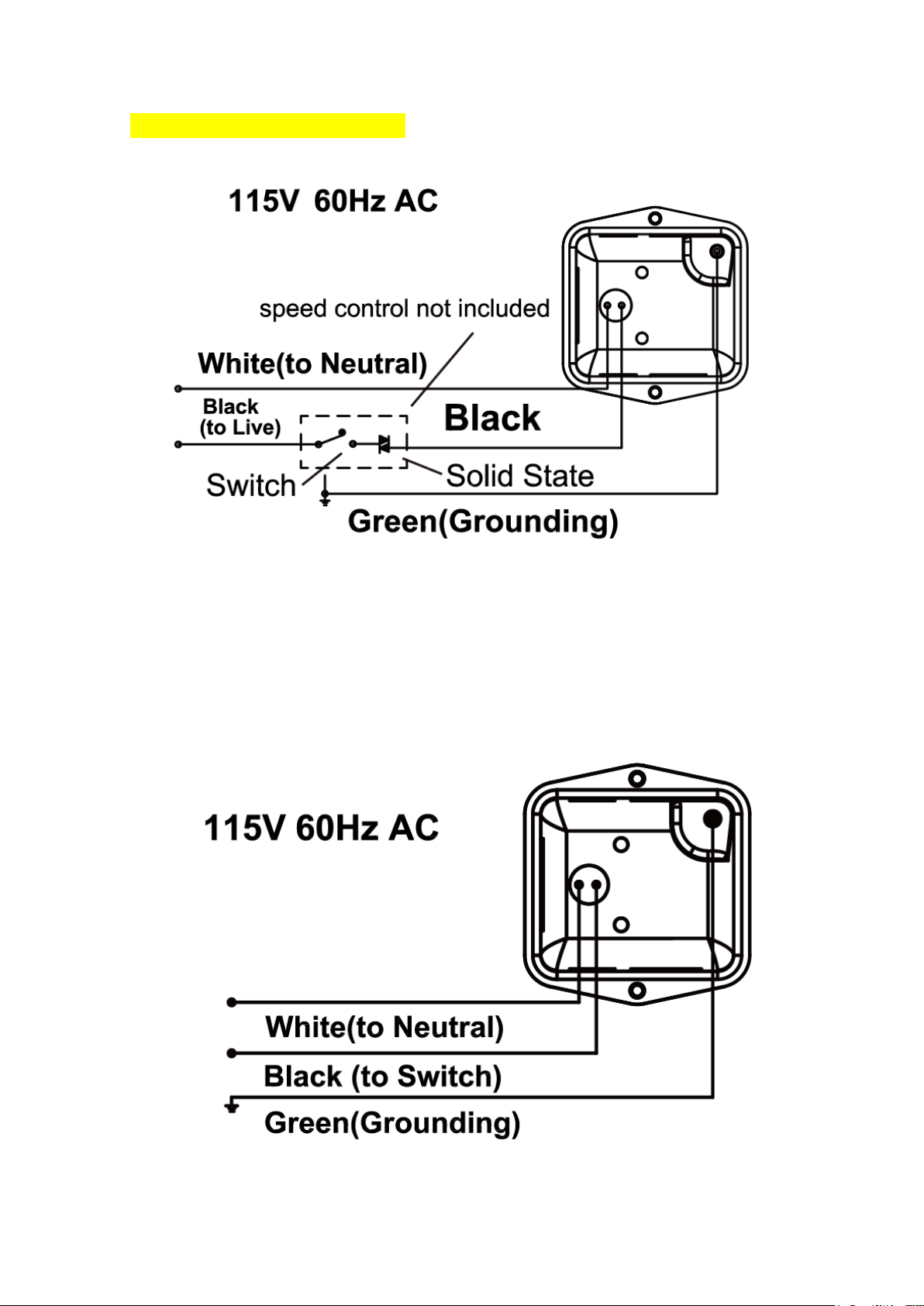
Wiring Diagram - 115-volt connection
for ILG8SF10V and ILG8SF12V.
Wiring Diagram - Speed Controllable. 115-volt connection.
for ILG8SF7V, ILG8SF16V,ILG8SF18V, ILG8SF20V, ILG8SF24V
6
Wiring Diagram - Single speed. 115-volt connection.
for ILG8SF18S, ILG8SF30S, ILG8SF36S
6. Using wire nut, connect the house power cable to the shutter fan wires
18 AWG (0.8 mm2 ) is the smallest conductor that shall be used for
branch-circuit wiring.
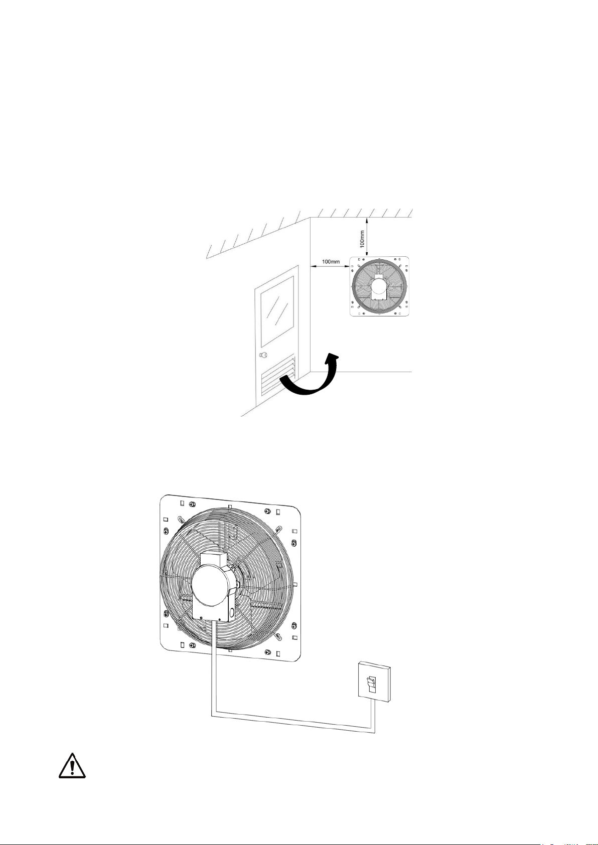
7. Please ensure the space has a gap for enough air to get into the
space. The fan installed on free space of at least 100mm above the
upper edges of the corner.
8. Please sleeve the connected wires with tube to prevent pulling.
Fan frame and motor must be securely and adequately grounded
Air Flow
For Indoor Use.
7
to a suitable electrical ground, such as a ground water pipe or ground
wiring system.
Power source
115V, 60Hz
Mounting Position
Vertical
Frame Material
Galvanized Steel
Shutter Blade Material
Aluminum Alloy
Propeller Material
Aluminum Alloy and Galvanized Steel
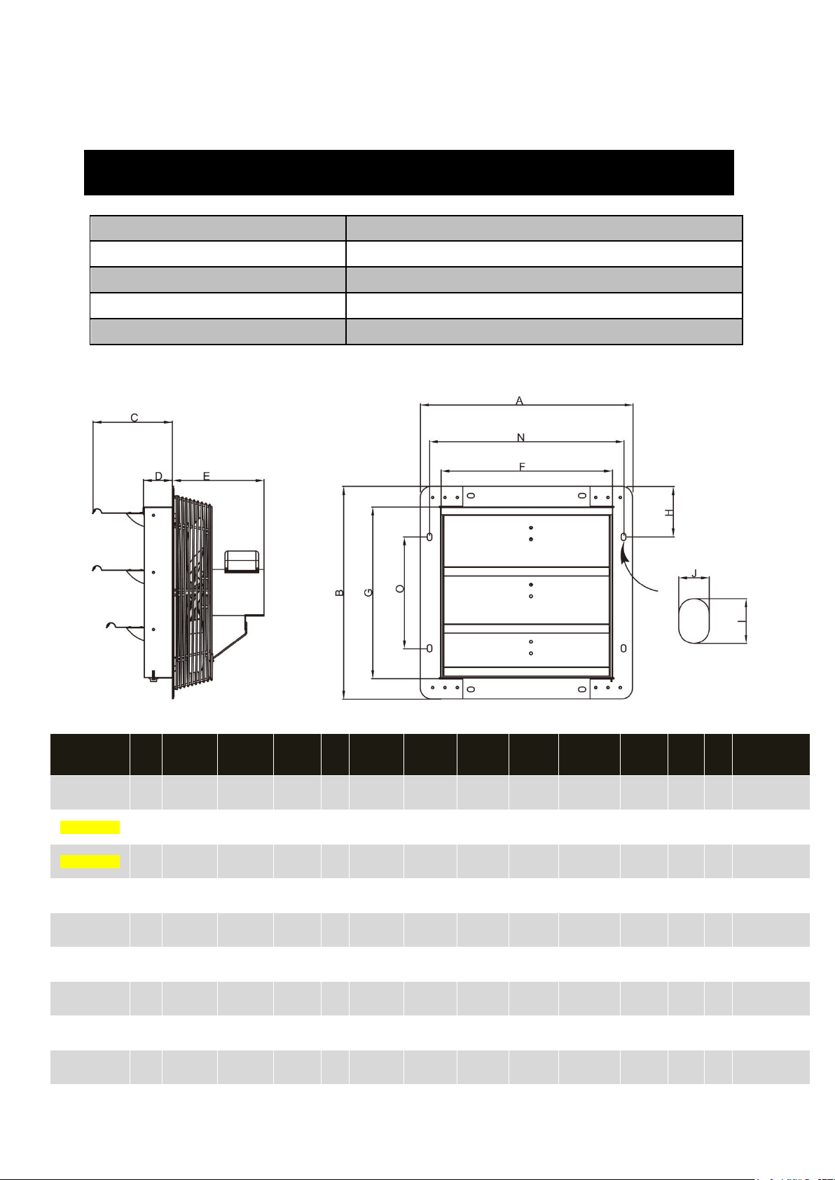
Dimensions (Inches)
MODEL
Prop
. Dia.
A
B
C
D
E
N
G
F
O
H
J
I
Suggested wall
opening (Sq)
ILG8SF7V 7" 11" 11" 5 3/4" 2" 5 7/8" 9 21/32" 8 1/8" 8 1/8" 4 1/16" 3 17/32"
9/32" 1/2"
8 1/2"
ILG8SF10V 10" 13" 13" 5 3/4" 2" 5 5/8" 11 21/32"
10 1/8" 10 1/8" 6" 3 17/32"
9/32" 1/2"
10 1/2"
ILG8SF12V 12" 15" 15" 5 3/4" 2" 5 5/8" 13 5/8" 12 1/8" 12 1/8" 8" 3 1/2" 9/32" 1/2"
13"
ILG8SF16V 16" 18 29/32"
18 29/32"
5 3/4" 2" 7 7/8" 17 3/4" 16" 16" 11 29/32" 3 17/32"
9/32" 1/2"
17"
ILG8SF18V 18" 21" 21" 5 3/4" 2" 8 3/4" 19 11/16"
18" 18" 14" 3 17/32"
9/32" 1/2"
19"
ILG8SF18S 18" 21" 21" 5 3/4" 2" 10 13/16"
19 11/16"
18" 18" 14" 3 17/32"
9/32" 1/2"
19"
ILG8SF20V 20" 23" 23" 5 3/4" 2" 11" 21 25/32"
20" 20" 16" 3 17/32"
9/32" 1/2"
21"
ILG8SF24V 24" 27" 27" 5 3/4" 2" 11" 25 21/32"
24 1/8" 24 1/8" 20 1/32" 3 17/32"
9/32" 1/2"
25"
ILG8SF30S 30" 33" 33" 5 3/4" 3" 13 3/32" 31 5/8" 30 1/8" 30 1/8" 26" 3 17/32"
9/32" 1/2"
31"
GENERAL SPECIFICATIONS
Figure 3

8
Performance
MODEL
Prop.
Dia.
Nom.
HP
Amps
Nom.
RPM
Bearing
Type
Sones @
0.0" SP @
5'
CFM Air Delivery @ Static
Pressure Shown
0.00"
0.125"
0.25"
ILG8SF7V 7" 1/25 0.40 1550 Sleeve 5.37 242 N/A N/A
ILG8SF10V 10" 1/20 0.60 1600 Sleeve 6.19 820 588 1200
ILG8SF12V 12" 1/20 0.60 1670 Sleeve 5.9 960 496 1300
ILG8SF16V 16" 1/20 0.85 1550 Ball 6.39 1200 416 180
ILG8SF18V 18" 1/15 0.85 1075 Ball 7.4 1736 1108 N/A
ILG8SF18S 18" 1/4 3.50 1725 Ball 7.28 3852 2836 2172
ILG8SF20V 20" 1/4 2.75 1075 Ball 6.67 3368 2312 1868
ILG8SF24V 24" 1/4 2.75 1075 Ball 7 4244 2676 2220
ILG8SF30S 30" 1/3 3.30 825 Ball 7.01 5088 3432 1552
ILG8SF36S 36" 1/2 6.00 825 Ball 8.24 6128 4380 2620
1. Keep the area free of objects that could impede air flow on both the
intake and exhaust side of fan.
2. For proper exhaust operation, a window, door, or louver should be
opened for fresh air intake on the opposite side of the area to be
ventilated.
3. Turn the fan ON; the shutter will open automatically. When the unit is
turned OFF, the shutter will close.
ILG8SF36S 36" 39" 39" 5 3/4" 3" 13 11/16"
37 21/32"
36 5/32" 36 5/32"
32" 3 17/32"
9/32" 1/2"
37"
OPERATING INSTRUCTIONS
9
1. Disconnect power source before servicing.
2. Periodically clean off accumulated dirt from the propeller, guard, motor,
and shutter.
Do not depend on any switch as the sole means of
disconnecting power when installing or servicing. If power
disconnect is not visible, utilize OSHA Lock out/Tag out procedure.
Failure to do so may result in fatal electrical shock.
Employ proper lock-out/tag-out procedures when performing
maintenance.
Symptom
Possible Cause(s)
Solution
Excessive noise
Dry motor bearings
Re-lubricate motor
bearings as per instructions
or replace motor.
Loose propeller
Tighten set screws on
propeller hub.
Bent or damaged
propeller
Replace propeller
Loose guard assembly or
motor fasteners.
Tighten as required to 15-
20 lbs. per inch.
Fan inoperative
Blown fuse or open
circuit breaker
Replace fuse or reset
circuit breaker
Defective motor
Replace motor
Switch in OFF position
Turn switch ON
Insufficient air
flow
Blocked intake or
exhaust opening
Clear intake and exhaust
openings of any
obstructions.
Clean motor, guard,
propeller, and shutter
assembly. Increase the
opening of the fresh air
intake.
Low voltage
Check electrical wiring.
Speed control set too low
Increase speed with
TROUBLESHOOTING
MAINTAINANCE
10
controller
Warranty Information
Register your product at our website:
Or visit iLivingUSA.com/register-product
Feedback
Love it? Help us make the product more for you.
Let us know with a customer review.
Please visit: https://www.amazon.com/review/review-your-purchases#
At iLiving USA, we are committed to bringing top quality products to our customers.
iLIVING USA
860 Mahler Road,
Burlingame, CA 94010
Tel: 1-800-317-1688
Email: [email protected]om
Like us on Facebook: https://www.facebook.com/ilivingusa/
Follow us on Twitter: @iLIVINGUSA