USER GUIDE & SERVICE MANUAL
ADA Collection
●
UANB115 / UANP115
●
15” Nugget Ice Machine
USER GUIDE & SERVICE MANUAL
u-line.com
Table of Contents
Intro
Safety
Safety and Warning
Disposal And Recycling
Installation
Environmental Requirements
Electrical
Cutout & Product Dimensions
Side by Side Installation
Water Hookup
Drain
Anti-Tip Bracket
General Installation
Grille Installation
Door Swing
Door Adjust
Maintenance
Cleaning
Cleaning Condenser
Extended Non-Use
Operating Instructions
Control Operation
Ice
Airflow and Product Loading
Service
Quick Guide
Troubleshooting
Wire Diagram
Reference diagrams
Product Liability
Warranty Claims
Parts
Ordering Replacement Parts
R600a Specifications
System Diagnosis Guide
Compressor Specifications
Troubleshooting Extended
Control Operation - Service
Thermistor
Warranty
USER GUIDE
u-line.com
Introduction
WELCOME TO U-LINE
Congratulations on your U-Line purchase. Your product comes from a company with over ve decades of premium modular ice
making, refrigeration, and wine preservation experience. U-Line creates products focused on functionality, style, and inspired
innovations — paying close attention to even the smallest details. Applications include residential, outdoor, ADA height
compliant, marine, and commercial. Complete product categories include Beverage Centers, Wine Refrigerators, Ice Machines,
Refrigerators, Freezers, and Dispensers.
Our advanced refrigeration systems, large and exible capacities, and Built-In to Stand Out
®
clean integrated look allow you
to preserve the right product, in the right place, at the right temperature. Since 2014, U-Line has been part of the Middleby
family of brands. All products are designed, engineered, and assembled in Milwaukee, Wisconsin, USA, and select products
are available worldwide.
PRODUCT INFORMATION
Looking for additional information on your product? User Guides, Spec Sheets, CAD Drawings, Compliance Documentation,
and Product Warranty information are all available for reference and download at u-line.com.
PROPERTY DAMAGE / INJURY CONCERNS
In the unlikely event property damage or personal injury is suspected related to a U-Line product, please take the following
steps:
1. U-Line Customer Care must be contacted immediately at +1.414.354.0300.
2. Service or repairs performed on the unit without prior written approval from U-Line is not permitted. If the unit has been
altered or repaired in the eld without prior written approval from U-Line, claims will not be eligible.
GENERAL INQUIRIES
U-Line Corporation
8900 N. 55th Street
Milwaukee, Wisconsin 53223 USA
Monday - Friday 8:00 am to 4:30 pm CST
T: +1.414.354.0300
Email: sales@u-line.com
u-line.com
CONNECT WITH US
SERVICE & PARTS ASSISTANCE
Monday - Friday 8:00 am to 4:30 pm CST
T: +1.414.354.0300
Service Email: onlineservice@u-line.com
Parts Email: onlineparts@u-line.com
Designed, engineered and assembled in WI, USA
3
USER GUIDE
u-line.com
Safety and Warning
Safety and Warning
NOTICE
Please read all instructions before installing,
operating, or servicing the appliance.
Use this appliance for its intended purpose only and follow
these general precautions with those listed throughout this
guide:
SAFETY ALERT DEFINITIONS
Throughout this guide are safety items labeled with a
Danger, Warning, or Caution based on the risk type:
Danger means that failure to follow this safety
statement will result in severe personal injury or
death.
Warning means that failure to follow this safety
statement could result in serious personal injury
or death.
Caution means that failure to follow this safety
statement may result in minor or moderate
personal injury, property, or equipment damage.
This unit contains R600a (Isobutane) which is a
ammable hydrocarbon. It is safe for regular
use. Do not use sharp objects to expedite
defrosting. Do not service without consulting the
“R600a specications” section included in the
User Guide. Do not damage the refrigerant
circuit.
Service must be done by factory authorized
service personnel. Any parts shall be replaced
with like components. Failure to comply could
increase the risk of possible ignition due to
incorrect parts or improper service.
CALIFORNIA PROPOSITION 65
This product contains chemicals known to the
state of California to cause cancer and birth
defects or other reproductive harm.
www.P65warnings.CA.gov
This equipment is to be installed with adequate
backow protection to comply with applicable
federal, state and local codes.
DANGER
!
DANGER
!
WARNING
!
CAUTION
!
CAUTION
!
WARNING
!
4
USER GUIDE
u-line.com
Disposal and Recycling
Disposal and Recycling
RISK OF CHILD ENTRAPMENT. Before you throw
away your old refrigerator or freezer, take o
the doors and leave shelves in place so children
may not easily climb inside.
If the unit is being removed from service for disposal,
check and obey all federal, state, and local regulations
regarding the disposal and recycling of refrigeration
appliances, and follow these steps completely:
1. Remove all consumable contents from the unit.
2. Unplug the electrical cord from its socket.
3. Remove the door(s)/drawer(s).
DANGER
!
5
USER GUIDE
Environmental Requirements
u-line.com
Environmental Requirements
This model is intended for indoor/interior applications only
and is not to be used in installations that are open/
exposed to natural elements.
This unit is designed to operate between 50°F (10°C) and
100°F (38°C). Higher ambient temperatures may reduce
the unit’s ability to reach low temperatures and/or reduce
ice production on applicable models.
For best performance, keep the unit out of direct sunlight
and away from heat generating equipment.
In climates where high humidity and dew points are
present, condensation may appear on outside surfaces.
This is considered normal. The condensation will
evaporate when the humidity drops.
CAUTION
!
Damages caused by ambient temperatures of
40°F (4°C) or below are not covered by the
warranty.
6
USER GUIDE
Electrical
u-line.com
Electrical
WARNING
!
SHOCK HAZARD — Electrical Grounding
Required. Never attempt to repair or perform
maintenance on the unit until the electricity has
been disconnected.
Never remove the round grounding prong from
the plug and never use a two-prong grounding
adapter.
Altering, cutting or removing power cord,
removing power plug, or direct wiring can cause
serious injury, fire, loss of property and/or life,
and will void the warranty.
Never use an extension cord to connect power to
the unit.
Always keep your working area dry.
NOTICE
Electrical installation must observe all state and
local codes. This unit requires connection to a
grounded (three-prong), polarized receptacle
that has been placed by a qualified electrician.
The unit requires a grounded and polarized 115 VAC,
60 Hz, 15A power supply (normal household current). An
individual, properly grounded branch circuit or circuit
breaker is recommended. A GFCI (ground fault circuit
interrupter) is usually not required for fixed location
appliances and is not recommended for your unit because
it could be prone to nuisance tripping. However, be sure
to consult your local codes.
See CUTOUT & PRODUCT DIMENSIONS for recommended
receptacle location.
7
USER GUIDE
u-line.com
Cutout & Product Dimensions
Cutout & Product Dimensions
PREPARE SITE
Your U-Line product has been designed for either free-
standing or built-in installation. When built-in, your unit
does not require additional air space for top, sides, or
rear. However, the front grille must NOT be obstructed,
and clearance is required for an electrical connection in
the rear.
CAUTION
!
Unit can NOT be installed behind a closed cabinet
door.
If you would like to align the face of the unit with
other adjacent cabinet doors, you may need to
alter the wall just behind the drain connection on
the unit to accommodate the drain.
CUTOUT DIMENSIONS
*15” Cutout width sucient if door protrudes beyond
adjacent cabinetry
PRODUCT DIMENSIONS
REAR
FRONT
TOP
SIDE
23-3/4"
(603 mm)
Minimum
15-1/4"
(387 mm)
32"
(813 mm)
to
33"
(838 mm)
See Electrical
Specifications
for Power Supply
4"
(102 mm)
7"
(178 mm)
Preferred location
for water line and
eletrical outlet is in
adjacent cabinet.
5/8"
(16 mm)
2”
(51 mm)
4”
(102 mm)
Drain
Water Line
7
½
”
(191 mm)
3
1⁄8
”
(80 mm)
4”
(102 mm)
7
½
”
(191 mm)
Power Cord
6 ft (183 cm)
14 15⁄16”
(379 mm)
3 ½”
(89 mm)
32” to 33”
(813 mm to
838 mm)
28”
(711 mm)
15 ½”
(394 mm)
1 7⁄8”
(48 mm)
21 1⁄16”
(535 mm)
10 3⁄16”
(259 mm)
22 11⁄16”
(576 mm)
24 9⁄16”
(624 mm)
4 3⁄16“ (106 mm)
8
USER GUIDE
Side-by-Side Installation
u-line.com
Side-by-Side Installation
Two units may be installed side-by-side.
Cutout width for a side-by-side installation is the cutout
dimension of a single unit times two.
No trim kit is required. However, 1/4" (6 mm) of space
needs to be maintained between the units to ensure
unobstructed door swing.
Units must operate from separate, properly grounded
electrical receptacles placed according to each unit’s
electrical specifications requirements.
Side-by-Side Installation with Bracket
1. Slide both units out so screws on top of units are easily
accessible.
2. Remove screws as shown below.
3. Place bracket over holes and attach to unit with two
screws removed in step 2 using a T-25 Torx driver.
Tighten screws fully.
4. Gently push units into position. Be careful not to
entangle the electrical cord or water line, if applicable.
5. Re-check the leveling, from front to back and side to
side. Make any necessary adjustments. The unit’s top
surface should be approximately 1/8" (3 mm) below
the countertop.
9
USER GUIDE
u-line.com
Water Hookup
Water Hookup
PREPARE PLUMBING
The water valve uses a standard 1/4” (6.35 mm)
compression tting. U-Line recommends using accessory
water hook up kit – part # 80-54674-00. The kit includes
a 10’ (3 m) braided exible water supply line and a brass
hose tting.
Plumbing installation must observe all state
and local codes. All water and drain connections
MUST BE made by a licensed/qualied plumbing
contractor. Failure to follow recommendations
and instructions may result in damage and/or
harm.
Water Supply
When connecting the water supply, please note the
following:
• Water Mineral Content:
◦
TDS: greater than 5 ppm (mg/l) but less than
400 ppm (mg/l)
◦
Hardness: Less than 200 mg/l (12 gpg)
• Not recommended for use with softened water
• A TDS meter is included with your unit
• Water Treatment Options
◦
TDS between 400-600 and/or hardness
between 13-20 can be treated by U-Line’s in-line water
filter accessories available at u-line.com or your local
dealer:
ULALINEFILTER — Standard
ULALINEFILTERL — Large
ULALINEFILTERHEAD — 3/8” NPT, initial
setup requires head & filter
• Use bypass level 6
Water Quality 1-3 Users 4+ Users
400 TDS and/or 12
gpg hardness or less
Optional
Standard Filter
Change 1x per year
Optional
Large Filter
Change 1x per year
401-600 TDS and/or
13-20 gpg hardness
Required
Large Filter
Change 1x per year
Required
Large Filter
Change 2x per year
601+ TDS, and/or
21+ gpg hardness
Contact your local water professional
• The water pressure should be between 20 and 120 psi
(138 and 827 kPa).
• The water line MUST have a shut-o valve in the
supply line.
• The water line should be looped into 2 coils. This
will allow the unit to be removed for cleaning and
servicing. Make certain that the tubing is not pinched
or damaged during installation.
Do not use any plastic water supply line. The line
is under pressure at all times. Plastic may crack
or rupture with age and cause damage to your
home.
Do not use tape or joint compound when
attaching a braided exible water supply line
that includes a rubber gasket. The gasket
provides an adequate seal – other materials
could cause blockage of the valve.
Failure to follow recommendations and
instructions may result in damage and/or harm,
ooding or void the product warranty.
Use new hose set. Do not reuse old hose set.
Turn o water supply and disconnect electrical
supply to unit prior to installation.
Use caution when handling back panel. The edges
could be sharp.
HOOKUP WATER
1. Turn o water supply and disconnect electrical supply
to product prior to attempting installation.
2. Remove the back panel.
CAUTION
!
CAUTION
!
CAUTION
!
10

USER GUIDE
u-line.com
Water Hookup
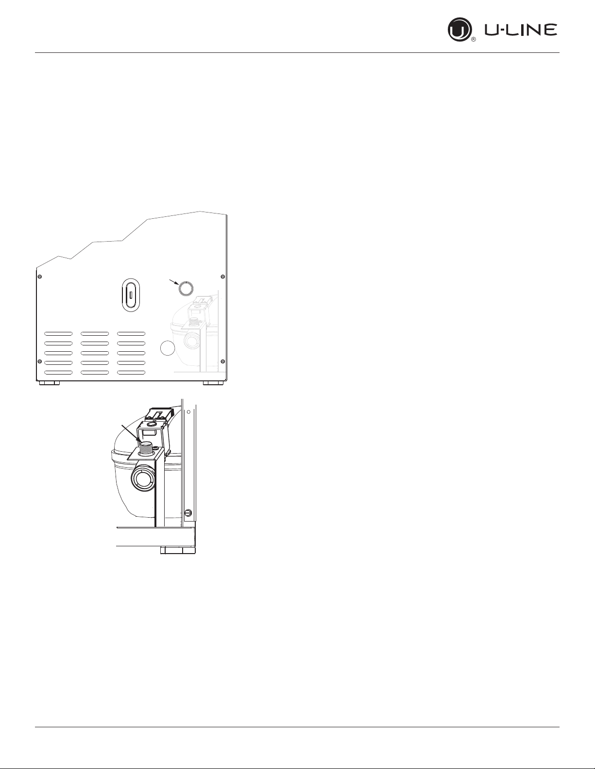
3. Thread water line through back panel hole (with
bushing).
4. Locate water valve inlet and connect to valve.
5. Turn on water supply and check for leaks.
6. Reinstall back panel.
3
4
11
USER GUIDE
u-line.com
Drain
If your U-Line unit did not come with a factory
installed drain pump you must use a gravity
style drain connection. For assistance in
determining if your unit has a pump please
contact U-Line. The oor drain must be large
enough to accommodate drainage from all
attached drains. Follow these guidelines when
installing drain lines to prevent water from
owing back into the ice maker storage bin and/
or potentially owing onto the oor, which may
result in personal injury or property damage
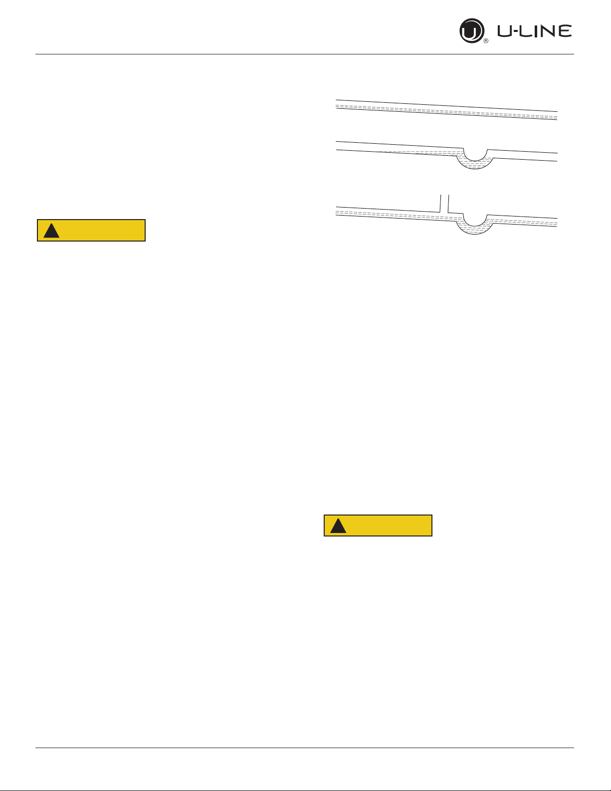
Failure to connect water supply or drain line
connections properly can result in personal injury
and property damage. Gravity drain connections
must be routed downward from the rest of the
unit at the rate of 1/4” per foot (1 cm per 50 cm).
Drain can NOT be located directly below the
unit. Unit has a solid base that will not allow the
unit to drain below itself.
There is a possibility that hose connections may
have loosened during shipment.
Verify all connections and ttings are free from
leaks.
This equipment is to be installed with adequate
backow protection to comply with applicable
federal, state and local codes
Model numbers including “CL” or “NB” do not include a
factory installed drain pump.
Model numbers including “CP” or “NP” include a factory
installed drain pump.
A gravity drain may be used if:
Drain line has at least a 1” drop per 48” (approximately
2 cm drop per 100 cm) of run.
Drain line does not create traps and is vented per local
code.
1. Cut the pre-installed drain tube to length.
2. Connect to your local plumbing per the local code.
3. If necessary, insulate drain line to prevent
condensation.
DRAIN CONNECTION
GRAVITY DRAIN
NOTICE
Drain
CAUTION
!
CAUTION
!
CAUTION
!
Normal
Proper Drain
With Trap
Poor Drainage, Water Will Back Up
With Trap and Vent
Proper Drain
12
USER GUIDE
u-line.com
Drain
The maximum lift for the P60 drain pump is
10 feet. This must be done as close to the rear of
the unit as possible.
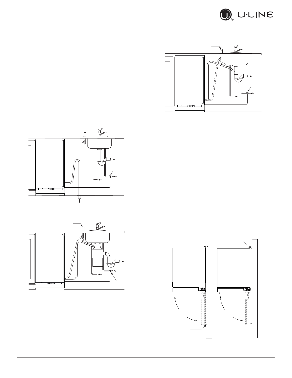
If your drain line will run up to a stand pipe, disposal
or spigot assembly, or does not otherwise meet the
requirements for a gravity drain, you may have ordered a
pre-installed U-Line P60 drain pump.
If you need to install a P60 drain pump into your unit, see
DRAIN PUMP section in the User Manual.
See below for typical installations requiring a drain pump.
FACTORY INSTALLED DRAIN PUMP
NOTICE
Cold
Water
Hot
Water
Waste
Waste
Shut-Off
Valve
Stand Pipe
P60 Pump Required
Air Gap
(Optional Hook-Up)
Cold
Water
Hot
Water
Waste
Shut-Off
Valve
Disposal Assembly
P60 Pump Required
Waste
Cold
Water
Shut-Off
Valve
Hot
Water
Air Gap
(Optional Hook-Up)
Y-Branch Tailpiece
P60 Pump Required
13
USER GUIDE
u-line.com
Anti-Tip Bracket
Anti-Tip Bracket
Use one of the methods below to secure the unit
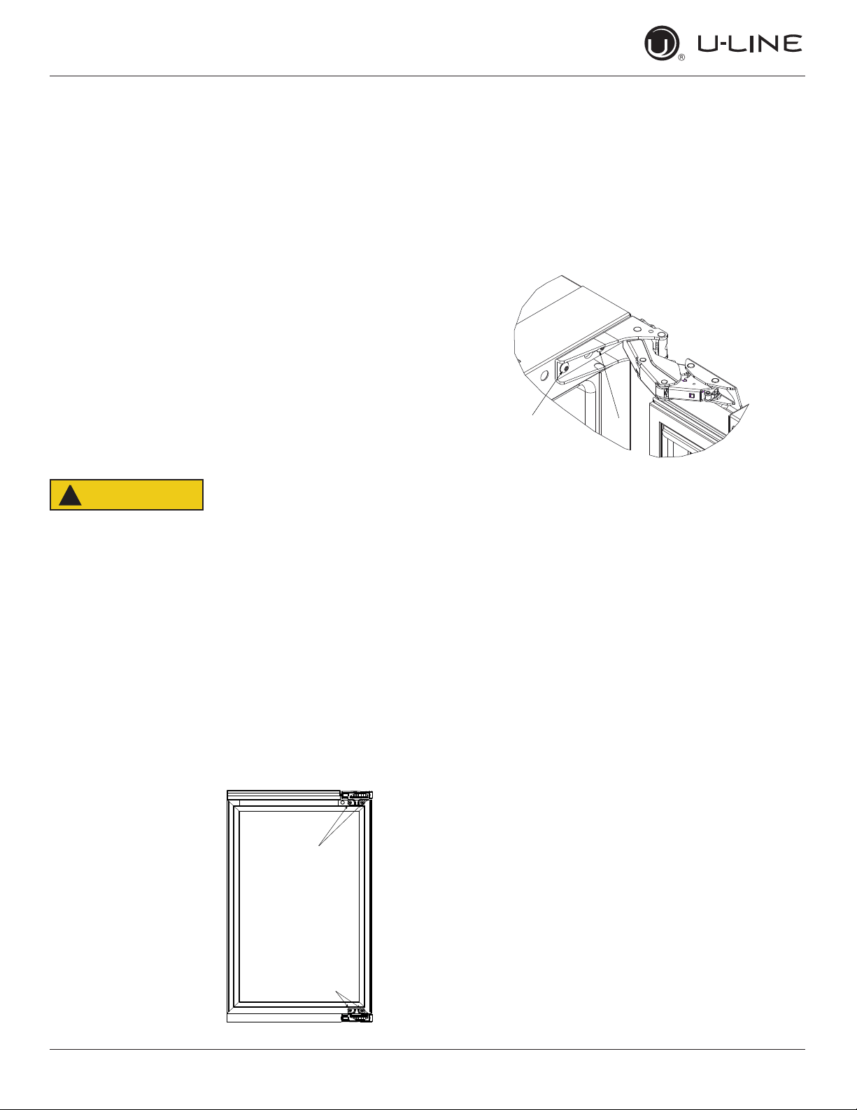
CABINET/COUNTER ANTI-TIP INSTALLATION
(For built-in applications)
1. Slide unit out so screws on front of unit are easily
accessible.
2. Remove the two screws from the front of the unit.
3. Bend bracket along one of the perforations to allow
attachment to the desired adjoining surface.
4. Gently push unit into position. Be careful not to
entangle the electrical cord or water line, if applicable.
5. Check to be sure the unit is level from front to back
and side to side. Make any necessary adjustments.
The unit’s top surface should be approximately 1⁄8”
(3 mm) below the countertop.
6. Secure bracket to adjoining surface.
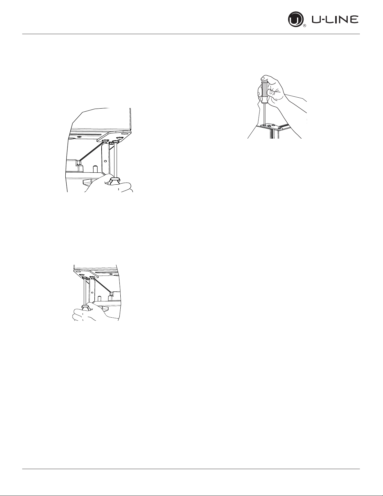
FLOOR MOUNTED ANTI-TIP INSTALLATION
(For free-standing applications)
1. Locate two anti-tip brackets included with the kit.
2. Place the unit into the area where it will be installed.
Check the door, sides, and top for a proper t. Also
test to make sure the door opens and closes freely.
3. Remove grille and place a mark on the oor at the
front of the unit. Also place a mark on the oor in the
center of the unit.
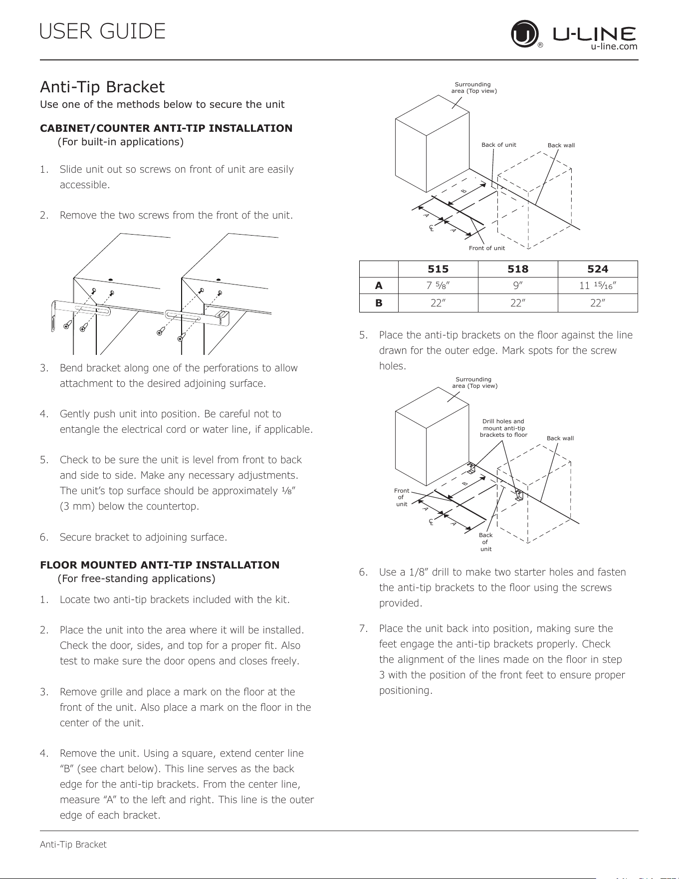
4. Remove the unit. Using a square, extend center line
“B” (see chart below). This line serves as the back
edge for the anti-tip brackets. From the center line,
measure “A” to the left and right. This line is the outer
edge of each bracket.
C
L
Back wall
Back of unit
Front of unit
Surrounding
area (Top view)
A
A
B
515 518 524
A 7 5⁄8” 9” 11 15⁄16”
B 22” 22” 22”
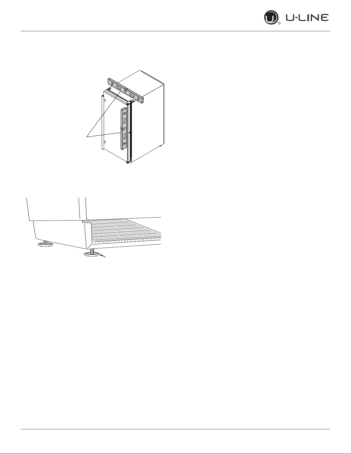
5. Place the anti-tip brackets on the oor against the line
drawn for the outer edge. Mark spots for the screw
holes.
C
L
Surrounding
area (Top view)
Drill holes and
mount anti-tip
brackets to floor
Back wall
Front
of
unit
Back
of
unit
A
A
B
6. Use a 1/8” drill to make two starter holes and fasten
the anti-tip brackets to the oor using the screws
provided.
7. Place the unit back into position, making sure the
feet engage the anti-tip brackets properly. Check
the alignment of the lines made on the oor in step
3 with the position of the front feet to ensure proper
positioning.
14
USER GUIDE
u-line.com
General Installation
General Installation
LEVELING INFORMATION
1. Use a level to
conrm the unit is
level. Level should
be placed along top
edge and side edge
as shown.
2. If the unit is not level, adjust the legs on the corners of
the unit as necessary.
3. Conrm the unit is level after each adjustment and
repeat the previous steps as needed.
INSTALLATION TIP
If the room oor is higher than the oor in the cutout
opening, adjust the rear legs to achieve a total unit rear
height of
1⁄8” (3 mm) less than opening’s rear height.
Shorten the unit height in the front by adjusting the front
legs. This allows the unit to be gently tipped into the
opening. Readjust the front legs to level the unit after it is
correctly positioned in the opening.
INSTALLATION
1. Plug in the power/electrical cord.
2. Gently push the unit into position. Be careful not
to entangle the cord or water and drain lines, if
applicable.
3. Re-check the leveling, from front to back and side to
side. Make any necessary adjustments. The unit’s top
surface should be approximately
1⁄8” (3 mm) below
the countertop.
4. Install the anti-tip bracket.
5. Remove interior packing material and wipe out the
inside of the unit with a clean, water-dampened cloth.
1
Turn to Adjust
15
USER GUIDE
Grille Installation
u-line.com
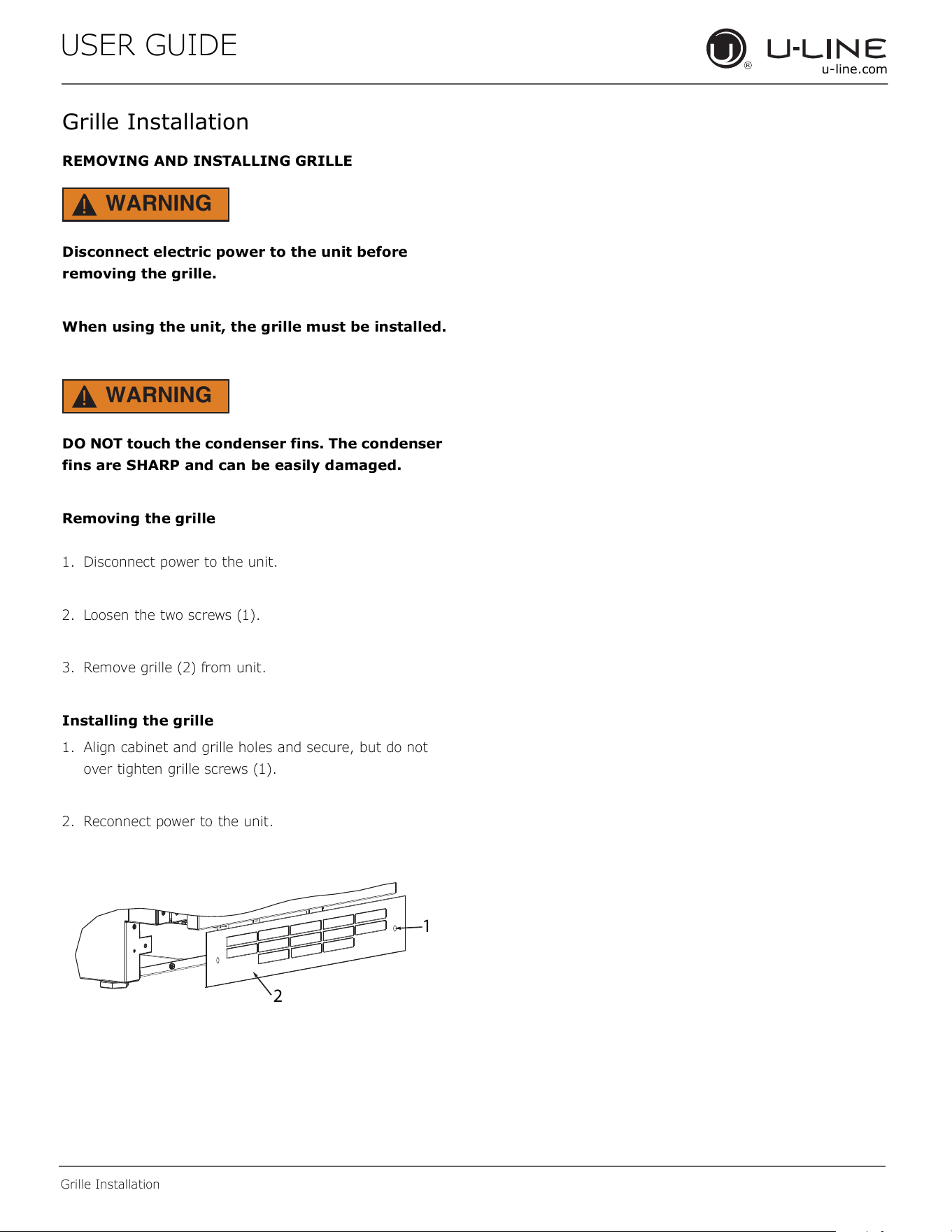
Grille Installation
REMOVING AND INSTALLING GRILLE
WARNING
!
Disconnect electric power to the unit before
removing the grille.
When using the unit, the grille must be installed.
WARNING
!
DO NOT touch the condenser fins. The condenser
fins are SHARP and can be easily damaged.
Removing the grille
1. Disconnect power to the unit.
2. Loosen the two screws (1).
3. Remove grille (2) from unit.
Installing the grille
1. Align cabinet and grille holes and secure, but do not
over tighten grille screws (1).
2. Reconnect power to the unit.
1
2
16

USER GUIDE
Door Swing
u-line.com
Door Swing
Units have a zero clearance for the door to open 90°,
when installed adjacent to cabinets.
Stainless Steel models require 2-1/8" (54 mm) door
clearance to accommodate the handle if installed next to a
wall.
Wall
90°
Door Swing
2-1/8" Min.
(54 mm)
17
USER GUIDE
u-line.com
Door Adjustments
Door Adjustments
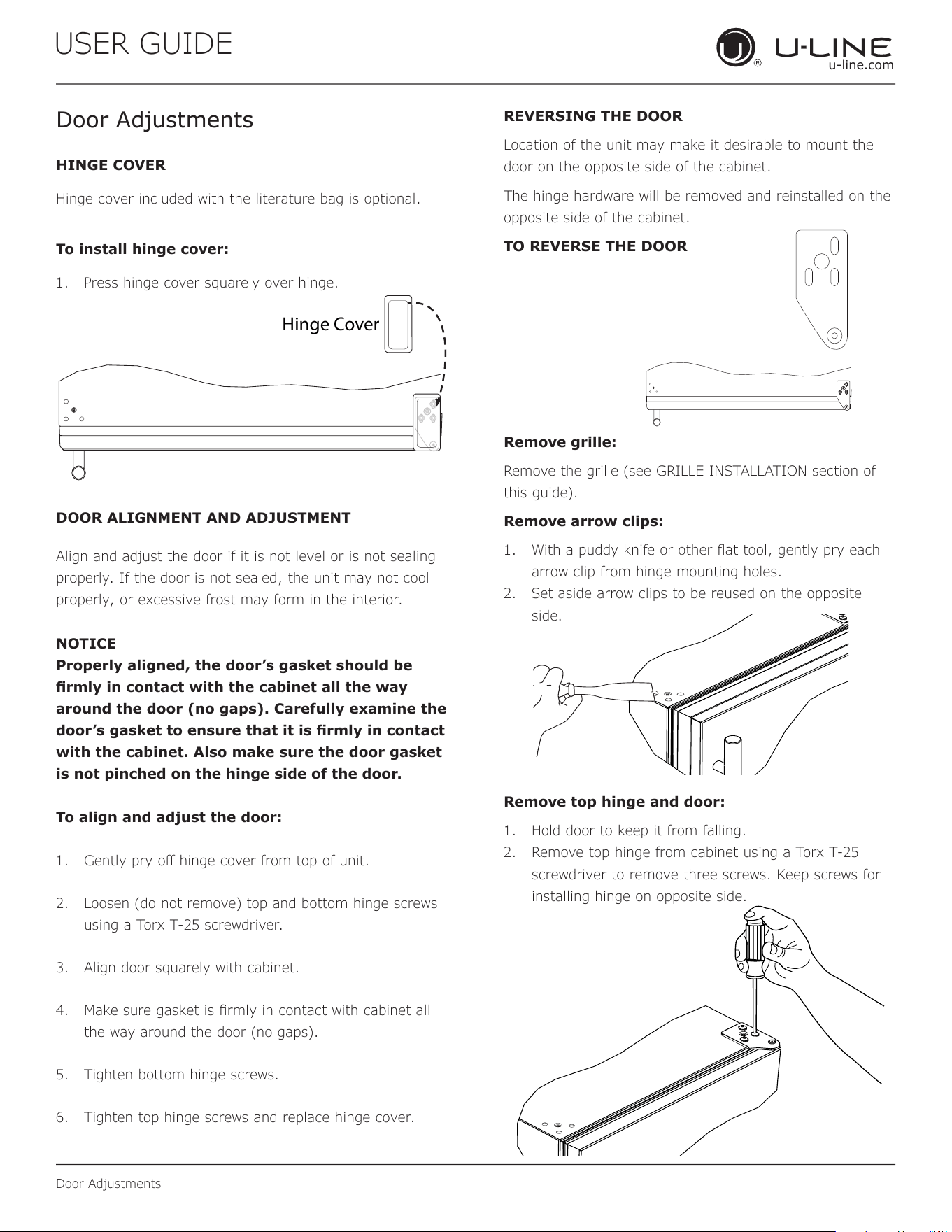
HINGE COVER
Hinge cover included with the literature bag is optional.
To install hinge cover:
1. Press hinge cover squarely over hinge.
DOOR ALIGNMENT AND ADJUSTMENT
Align and adjust the door if it is not level or is not sealing
properly. If the door is not sealed, the unit may not cool
properly, or excessive frost may form in the interior.
NOTICE
Properly aligned, the door’s gasket should be
rmly in contact with the cabinet all the way
around the door (no gaps). Carefully examine the
door’s gasket to ensure that it is rmly in contact
with the cabinet. Also make sure the door gasket
is not pinched on the hinge side of the door.
To align and adjust the door:
1. Gently pry o hinge cover from top of unit.
2. Loosen (do not remove) top and bottom hinge screws
using a Torx T-25 screwdriver.
3. Align door squarely with cabinet.
4. Make sure gasket is rmly in contact with cabinet all
the way around the door (no gaps).
5. Tighten bottom hinge screws.
6. Tighten top hinge screws and replace hinge cover.
REVERSING THE DOOR
Location of the unit may make it desirable to mount the
door on the opposite side of the cabinet.
The hinge hardware will be removed and reinstalled on the
opposite side of the cabinet.
TO REVERSE THE DOOR
Remove grille:
Remove the grille (see GRILLE INSTALLATION section of
this guide).
Remove arrow clips:
1. With a puddy knife or other at tool, gently pry each
arrow clip from hinge mounting holes.
2. Set aside arrow clips to be reused on the opposite
side.
Remove top hinge and door:
1. Hold door to keep it from falling.
2. Remove top hinge from cabinet using a Torx T-25
screwdriver to remove three screws. Keep screws for
installing hinge on opposite side.
Hinge Cover
18

USER GUIDE
u-line.com
Door Adjustments
3. Remove door by tilting forward and lifting door o
bottom hinge. Retain shoulder washers; they will be
reused.
4. Insert arrow clips into holes.
Remove bottom hinge:
1. Remove bottom hinge from cabinet using a T-25 TORX
screw driver to remove three screws.
2. Remove corresponding screws on opposite side of
cabinet. On some models there may be a nut behind
one or both screws on either side.
Install bottom hinge:
Install two or three screws, depending on model. Replace
nuts if used.
Prepare door for reinstallation:
1. Remove gasket. This will reveal mounting holes for the
magnet assembly.
2. Remove magnet assembly from door with T-10 TORX
driver. Be sure to only remove the two screws holding
the assembly to the door. Reinstall on the opposite
end of the door.
3. Rotate gasket 180°, aligning notch with magnet
assembly and pressing rmly into the gasket channel
starting at the corners.
4. Rotate door 180° to reverse.
USER GUIDE
u-line.com
Door Adjustments
4. Remove door by tilting forward and lifting door o
bottom hinge. Retain shoulder washers; they will be
reused.
5. Remove three screws from hinge holes on the
opposite side. Reinstall into holes where the hinge was
removed. Take care not to scratch cabinet.
Remove bottom hinge:
1. Remove bottom hinge from cabinet using a 1/4”
socket.
2. Remove corresponding screws on opposite side of
cabinet. On some models there may be a nut behind
one or both screws on either side.
Install bottom hinge:
Install two or three screws, depending on model. Replace
nuts if used.
Prepare door for reinstallation:
1. Remove outside gasket.
2. Rotate gasket 180
º and press firmly into the gasket
channel starting at the corners.
3. Reposition inside gasket.
a.
b.
c. Using a flat tool, such as a putty knife, gently pry
off inside gasket.
d. Rotate door 180
º
and
line up top edge of gasket to
marks on door and rmly press gasket into place.
(If the original adhesive no longer holds the gasket
in place, it may be necessary to apply a strip of
two-sided tape.)
Install top hinge and door:
1. Remove pivot screw from hinge, ip hinge over, and
install the pivot screw in the same hole from the
opposite surface.
2. Lift the door onto the bottom hinge.
3. Align edge of the hinge with the outer edge of the unit.
4. Tighten three screws and replace hinge cover.
Align and adjust the door:
Align and adjust the door (see DOOR ALIGNMENT AND
ADJUSTMENT)
Install grille
Before rotating door,
measure distance from
top of outside gasket to
top of inside gasket.
Measure the same
distance up from the
outside edge of the
gasket and place a light
mark on each side of
door.
Place a mark
on each side
Top of Door
a
b
Top Hinge
Right Side
Top Hinge
Left Side
Pivot
Screw
19
USER GUIDE
u-line.com
Control Operation
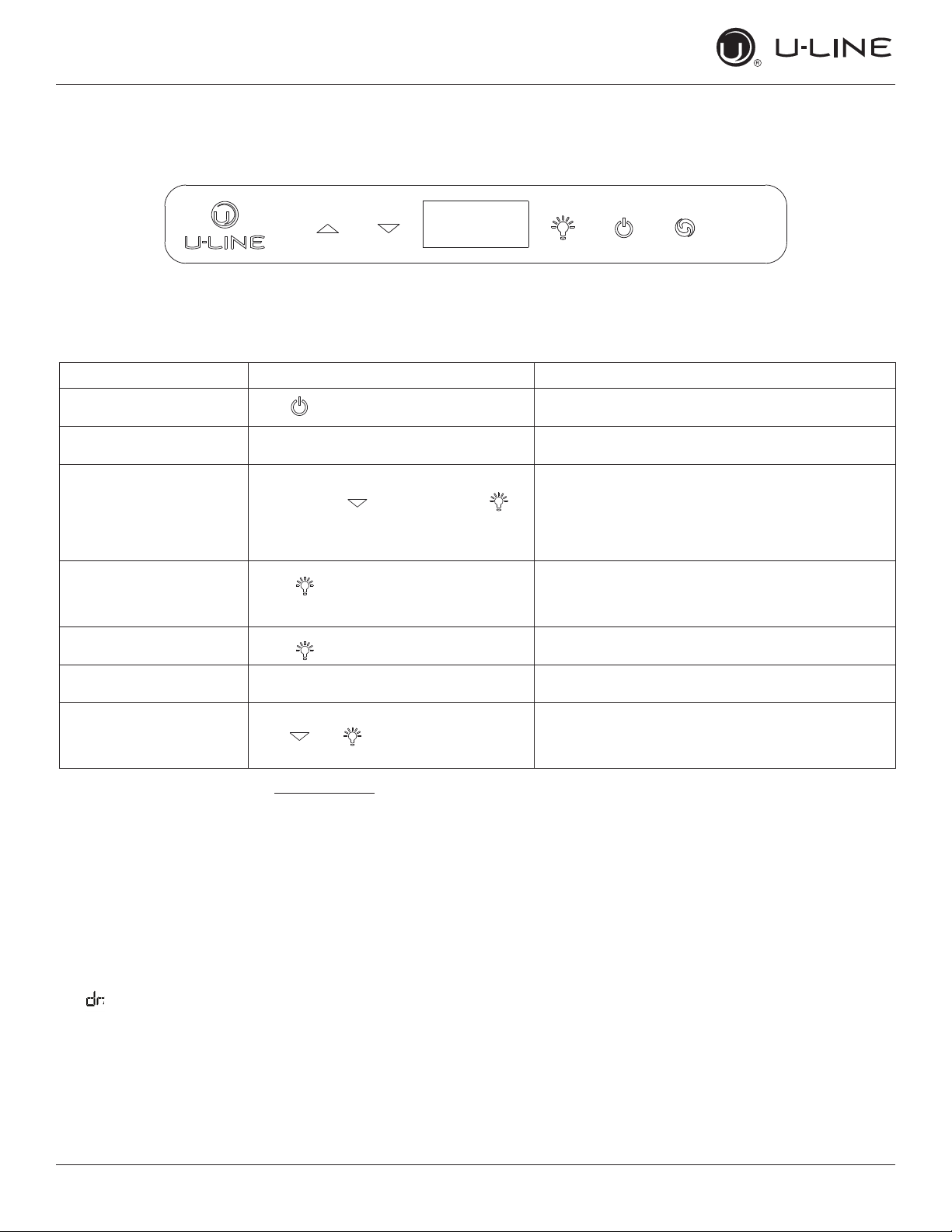
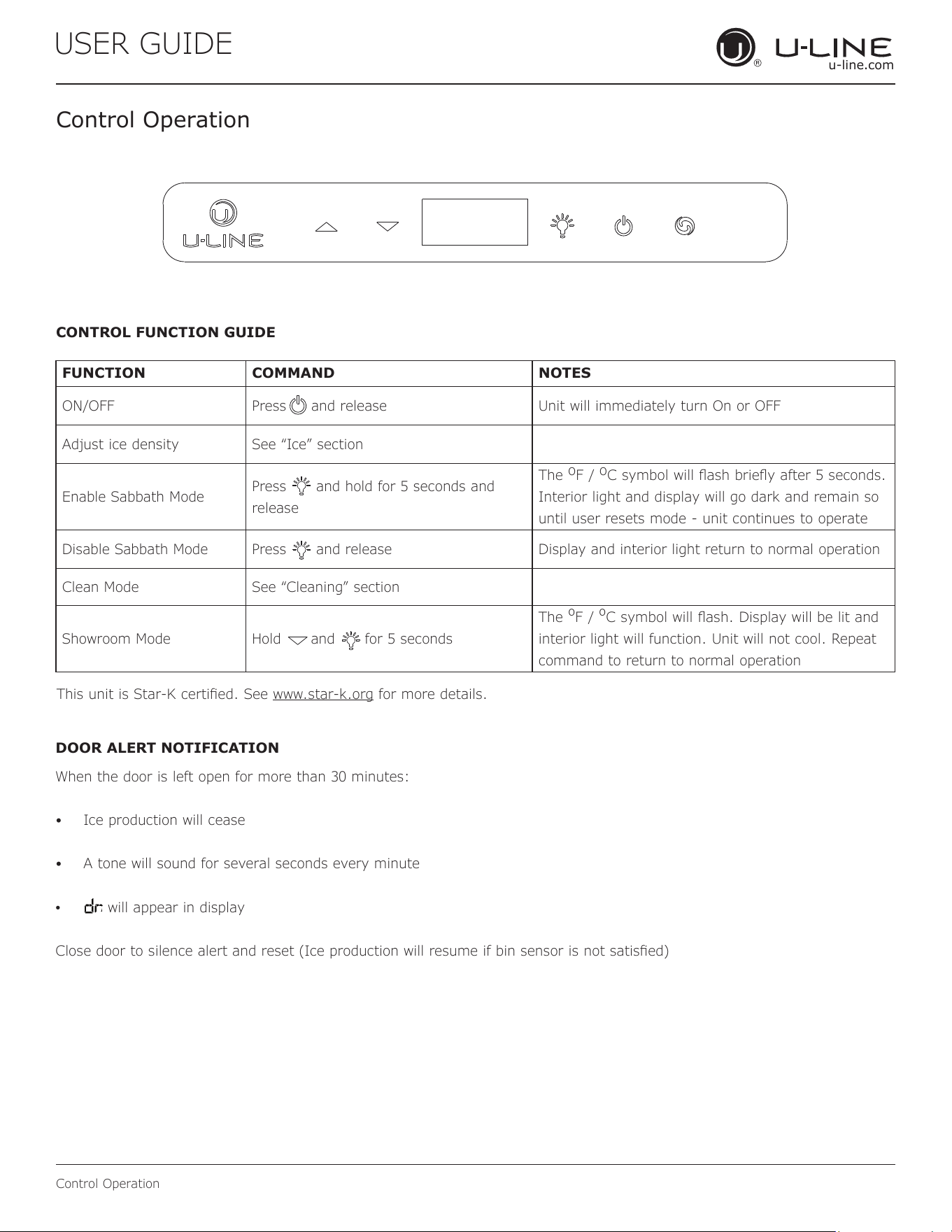
Control Operation
CONTROL FUNCTION GUIDE
FUNCTION COMMAND NOTES
ON/OFF Press and release Unit will immediately turn On or OFF
Adjust ice density See “Ice” section
Enable Sabbath Mode
Press and hold for 5 seconds and
release
The
o
F /
o
C symbol will ash briey after 5 seconds.
Interior light and display will go dark and remain so
until user resets mode - unit continues to operate
Disable Sabbath Mode Press and release Display and interior light return to normal operation
Clean Mode See “Cleaning” section
Showroom Mode Hold and for 5 seconds
The
º
F /
º
C symbol will ash. Display will be lit and
interior light will function. Unit will not cool. Repeat
command to return to normal operation
This unit is Star-K certied. See www.star-k.org for more details.
DOOR ALERT NOTIFICATION
When the door is left open for more than 30 minutes:
• Ice production will cease
• A tone will sound for several seconds every minute
• will appear in display
Close door to silence alert and reset (Ice production will resume if bin sensor is not satised)
20
USER GUIDE
Ice
u-line.com
Ice
The Nugget Ice Machine produces cylindrical bits of
compressed ice approximately
3
/
4
” x
1
/
2
”.
Ice is produced until the machine senses the bin is full. As
ice slowly melts in the bin, the level of ice drops and ice
production resumes. This ensures a constant supply of
fresh ice is always available.
The factory default ice setting is 0, which produces a firm
and compact ice nugget. U-Line’s exclusive U-Choose™
ice adjustability feature allows you five levels of
adjustment from 0 to -5. At -5 the ice is soft and
chewable.
To adjust the ice density:
1. Hold for 5 seconds - display will flash current ice
setting
2. Adjust using or
3. Confirm setting by pressing
21
USER GUIDE
Airflow and Product Loading
u-line.com
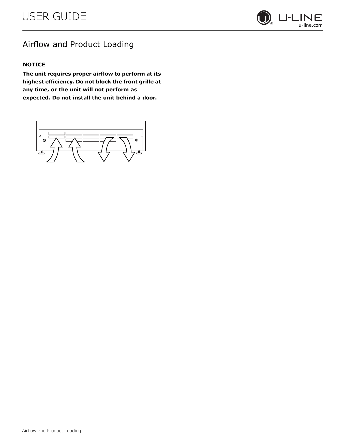
Airflow and Product Loading
NOTICE
The unit requires proper airflow to perform at its
highest efficiency. Do not block the front grille at
any time, or the unit will not perform as
expected. Do not install the unit behind a door.
22
USER GUIDE
u-line.com
Cleaning
Integrated Models
To clean integrated panels, use household cleaner per the
cabinet manufacturer’s recommendations.
INTERIOR CLEANING
Disconnect power to the unit.
Clean the interior and all removed components using a mild
nonabrasive detergent and warm solution applied with a
soft sponge or non-abrasive cloth.
Rinse the interior using a soft sponge and clean water.
Do not use any solvent-based or abrasive
cleaners. These types of cleaners may transfer taste
and/or odor to the interior products and damage or discolor
the interior.
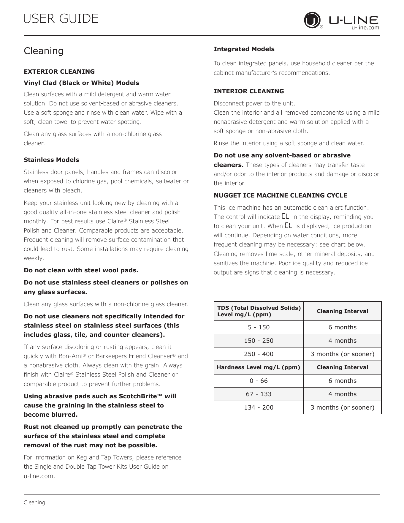
NUGGET ICE MACHINE CLEANING CYCLE
This ice machine has an automatic clean alert function.
The control will indicate CL in the display, reminding you
to clean your unit. When CL is displayed, ice production
will continue. Depending on water conditions, more
frequent cleaning may be necessary: see chart below.
Cleaning removes lime scale, other mineral deposits, and
sanitizes the machine. Poor ice quality and reduced ice
output are signs that cleaning is necessary.
Clean surfaces with a mild detergent and warm water
solution. Do not use solvent-based or abrasive cleaners.
Use a soft sponge and rinse with clean water. Wipe with a
soft, clean towel to prevent water spotting.
Clean any glass surfaces with a non-chlorine glass
cleaner.
EXTERIOR CLEANING
Vinyl Clad (Black or White) Models
Stainless Models
Stainless door panels, handles and frames can discolor
when exposed to chlorine gas, pool chemicals, saltwater or
cleaners with bleach.
Keep your stainless unit looking new by cleaning with a
good quality all-in-one stainless steel cleaner and polish
monthly. For best results use Claire
®
Stainless Steel
Polish and Cleaner. Comparable products are acceptable.
Frequent cleaning will remove surface contamination that
could lead to rust. Some installations may require cleaning
weekly.
Do not clean with steel wool pads.
Do not use stainless steel cleaners or polishes on
any glass surfaces.
Clean any glass surfaces with a non-chlorine glass cleaner.
Do not use cleaners not specically intended for
stainless steel on stainless steel surfaces (this
includes glass, tile, and counter cleaners).
If any surface discoloring or rusting appears, clean it
quickly with Bon-Ami
®
or Barkeepers Friend Cleanser
®
and
a nonabrasive cloth. Always clean with the grain. Always
nish with Claire
®
Stainless Steel Polish and Cleaner or
comparable product to prevent further problems.
Using abrasive pads such as ScotchBrite™ will
cause the graining in the stainless steel to
become blurred.
Rust not cleaned up promptly can penetrate the
surface of the stainless steel and complete
removal of the rust may not be possible.
For information on Keg and Tap Towers, please reference
the Single and Double Tap Tower Kits User Guide on
u-line.com.
Cleaning
TDS (Total Dissolved Solids)
Level mg/L (ppm)
Cleaning Interval
5 - 150 6 months
150 - 250 4 months
250 - 400 3 months (or sooner)
Hardness Level mg/L (ppm) Cleaning Interval
0 - 66 6 months
67 - 133 4 months
134 - 200 3 months (or sooner)
23
USER GUIDE
u-line.com
Cleaning
Under normal conditions cleaning should be done
when the display shows CL. You may initiate a
cleaning cycle at any time by pressing and holding
the clean button for 10 seconds. 0 1 will appear
in the display indicating the start of the cleaning
process.
Failure to clean may reduce the quality and quantity of ice
produced. Once the clean cycle begins, it can be canceled
by pressing three times. Press once more to start
making ice. The clean cycle will automatically cancel if user
fails to activate control at steps 2, 3b, and 5b within 2 hours.
Required for cleaning:
• Clean potable water
• Bucket and cleaning sponge
• Internal water lter (if applicable) —
ULANUGGETFILTER**
• SafeCLEAN Plus™ Cleaner — ULANUGGETCLEAN**
• Hose (7⁄16” ID x 9⁄16” OD) and funnel
◦
Register your product at u-line.com and receive
a free cleaning kit - ULANUGGETCLEANKIT**
(cleaner, hose, & funnel)
** available for purchase at u-line.com or your local dealer
Need more cleaner? Visit u-line.com
CAUTION
!
Use only SafeCLEAN Plus™ Cleaner. Use of any
other cleaner may damage the nish of the
evaporator and will void the warranty.
Follow safety and handling instructions printed on
the SafeCLEAN Plus™ bottle.
Notice:
Select models include a water lter. The lter
must remain in place when using and cleaning
the machine. The lter is designed to lter out
scale, sediment, particles and cloudiness as well
as reduce chlorine and other o tastes and odors.
U-Line recommends replacing the lter (Part No.
ULANUGGETFILTER) when you clean your machine.
The lter is available at u-line.com.
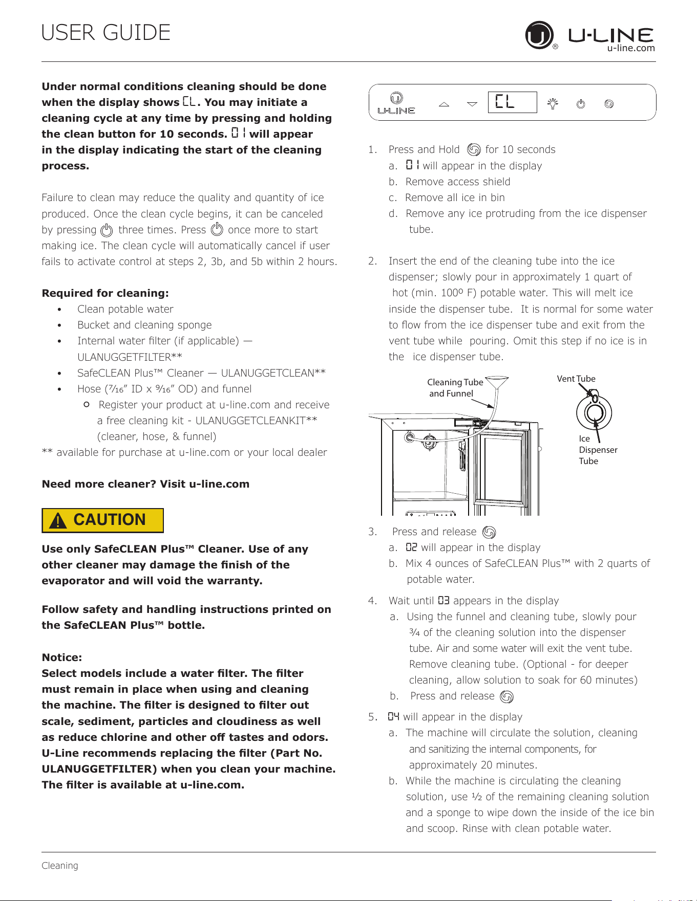
1. Press and Hold for 10 seconds
a. 0 1 will appear in the display
b. Remove access shield
c. Remove all ice in bin
d. Remove any ice protruding from the ice dispenser
tube.
2. Insert the end of the cleaning tube into the ice
dispenser; slowly pour in approximately 1 quart of
hot (min. 100º F) potable water. This will melt ice
inside the dispenser tube. It is normal for some water
to ow from the ice dispenser tube and exit from the
vent tube while pouring. Omit this step if no ice is in
the ice dispenser tube.
3. Press and release
a. 02 will appear in the display
b. Mix 4 ounces of SafeCLEAN Plus™ with 2 quarts of
potable water.
4. Wait until 03 appears in the display
a. Using the funnel and cleaning tube, slowly pour
3⁄4 of the cleaning solution into the dispenser
tube. Air and some water will exit the vent tube.
Remove cleaning tube. (Optional - for deeper
cleaning, allow solution to soak for 60 minutes)
b. Press and release
5. 04 will appear in the display
a. The machine will circulate the solution, cleaning
and sanitizing the internal components, for
approximately 20 minutes.
b. While the machine is circulating the cleaning
solution, use 1⁄2 of the remaining cleaning solution
and a sponge to wipe down the inside of the ice bin
and scoop. Rinse with clean potable water.
Cl
Cleaning Tube
and Funnel
Ice
Dispenser
Tube
Vent Tube
24
USER GUIDE
u-line.com
Cleaning
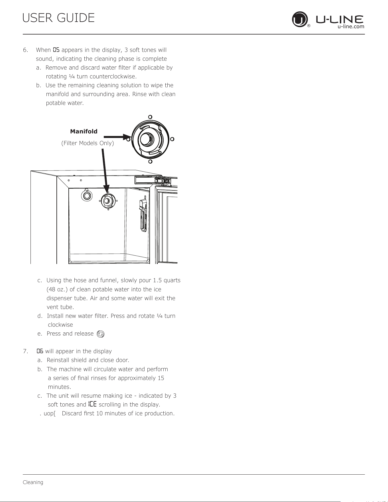
6. When 05 appears in the display, 3 soft tones will
sound, indicating the cleaning phase is complete
a. Remove and discard water lter if applicable by
rotating 1⁄4 turn counterclockwise.
b. Use the remaining cleaning solution to wipe the
manifold and surrounding area. Rinse with clean
potable water.
c. Using the hose and funnel, slowly pour 1.5 quarts
(48 oz.) of clean potable water into the ice
dispenser tube. Air and some water will exit the
vent tube.
d. Install new water lter. Press and rotate 1⁄4 turn
clockwise
e. Press and release
7. 06 will appear in the display
a. Reinstall shield and close door.
b. The machine will circulate water and perform
a series of nal rinses for approximately 15
minutes.
c. The unit will resume making ice - indicated by 3
soft tones and ICE scrolling in the display.
. uop[ Discard rst 10 minutes of ice production.
Manifold
(Filter Models Only)
25
USER GUIDE
Cleaning Condenser
u-line.com
Cleaning Condenser
INTERVAL - EVERY SIX MONTHS
To maintain operational efficiency, keep the front grille
free of dust and lint, and clean the condenser when
necessary. Depending on environmental conditions, more
or less frequent cleaning may be necessary.
WARNING
!
Disconnect electric power to the unit before
cleaning the condenser.
DO NOT touch the condenser fins. The condenser
fins are SHARP and can be easily damaged.
NOTICE
DO NOT use any type of cleaner on the
condenser unit. Condenser may be cleaned using
a vacuum, soft brush or compressed air.
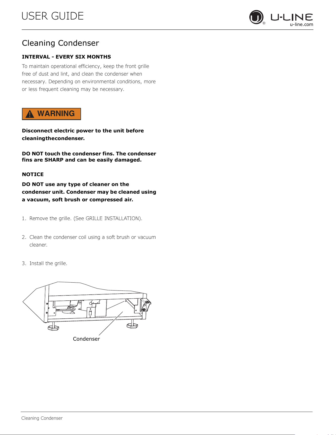
1. Remove the grille. (See GRILLE INSTALLATION).
2. Clean the condenser coil using a soft brush or vacuum
cleaner.
3. Install the grille.
Condenser
26
USER GUIDE
Extended Non-Use
u-line.com
Extended Non-Use
VACATION/HOLIDAY, PROLONGED SHUTDOWN
The following steps are recommended for periods of
extended non-use:
1. Remove all consumable content from the unit.
2. Disconnect the power cord from its outlet/socket and
leave it disconnected until the unit is returned to
service.
3. Turn off the water supply.
4. If ice is on the evaporator, allow ice to thaw naturally.
5. Clean and dry the interior of the cabinet. Ensure all
water has been removed from the unit.
6. Disconnect the water and drain line (if applicable)
making sure all water is removed from the lines.
7. The door must remain open to prevent formation of
mold and mildew. Open door a minimum of 2"
(50 mm) to provide the necessary ventilation.
WINTERIZATION
If the unit will be exposed to temperatures of 40°F (5°C)
or less, the steps above must be followed. In addition, P60
drain pumps in clear ice machines must be drained
according to the following procedure:
1. Remove the drain pump from the ice machine.
2. Drain the water in the pump’s reservoir by turning the
pump upside down and allowing the water to drain
through the pump’s inlet and vent tube fittings.
3. After water is drained, reinstall the drain pump and
reattach all connections.
For questions regarding winterization, please
call U-Line at 800.779.2547.
CAUTION
!
Damage caused by freezing temperatures is not
covered by the warranty.
Do not put anti-freeze in your unit.
27
USER GUIDE
u-line.com
Quick Guide
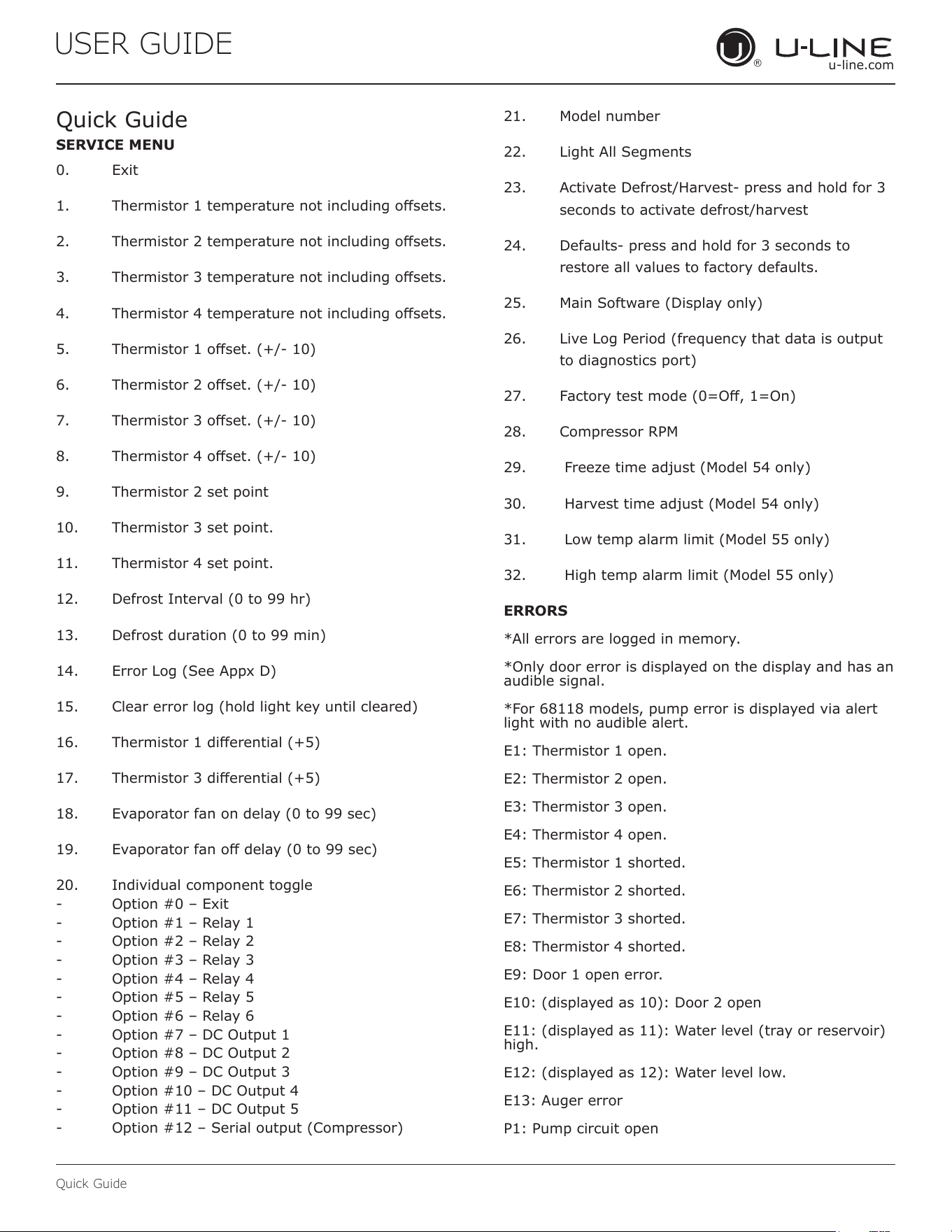
Quick Guide
0. Exit
1. Thermistor1temperaturenotincludingosets.
2. Thermistor2temperaturenotincludingosets.
3. Thermistor3temperaturenotincludingosets.
4. Thermistor4temperaturenotincludingosets.
5. Thermistor1oset.(+/-10)
6. Thermistor2oset.(+/-10)
7. Thermistor3oset.(+/-10)
8. Thermistor4oset.(+/-10)
9. Thermistor 2 set point
10. Thermistor 3 set point.
11. Thermistor 4 set point.
12. DefrostInterval(0to99hr)
13. Defrostduration(0to99min)
14. ErrorLog(SeeAppxD)
15. Clearerrorlog(holdlightkeyuntilcleared)
16. Thermistor1dierential(+5)
17. Thermistor3dierential(+5)
18. Evaporatorfanondelay(0to99sec)
19. Evaporatorfanodelay(0to99sec)
20. Individual component toggle
- Option#0–Exit
- Option#1–Relay1
- Option#2–Relay2
- Option#3–Relay3
- Option#4–Relay4
- Option#5–Relay5
- Option#6–Relay6
- Option#7–DCOutput1
- Option#8–DCOutput2
- Option#9–DCOutput3
- Option#10–DCOutput4
- Option#11–DCOutput5
- Option#12–Serialoutput(Compressor)
21. Model number
22. LightAllSegments
23. ActivateDefrost/Harvest-pressandholdfor3
secondstoactivatedefrost/harvest
24. Defaults-pressandholdfor3secondsto
restoreallvaluestofactorydefaults.
25. MainSoftware(Displayonly)
26. LiveLogPeriod(frequencythatdataisoutput
todiagnosticsport)
27. Factorytestmode(0=O,1=On)
28. CompressorRPM
29. Freezetimeadjust(Model54only)
30. Harvesttimeadjust(Model54only)
31. Lowtempalarmlimit(Model55only)
32. Hightempalarmlimit(Model55only)
ERRORS
*Allerrorsareloggedinmemory.
*Onlydoorerrorisdisplayedonthedisplayandhasan
audible signal.
*For68118models,pumperrorisdisplayedviaalert
lightwithnoaudiblealert.
E1: Thermistor 1 open.
E2: Thermistor 2 open.
E3: Thermistor 3 open.
E4: Thermistor 4 open.
E5: Thermistor 1 shorted.
E6: Thermistor 2 shorted.
E7: Thermistor 3 shorted.
E8: Thermistor 4 shorted.
E9: Door 1 open error.
E10:(displayedas10):Door2open
E11:(displayedas11):Waterlevel(trayorreservoir)
high.
E12:(displayedas12):Waterlevellow.
E13:Augererror
P1: Pump circuit open
SERVICE MENU
28
USER GUIDE
u-line.com
Quick Guide
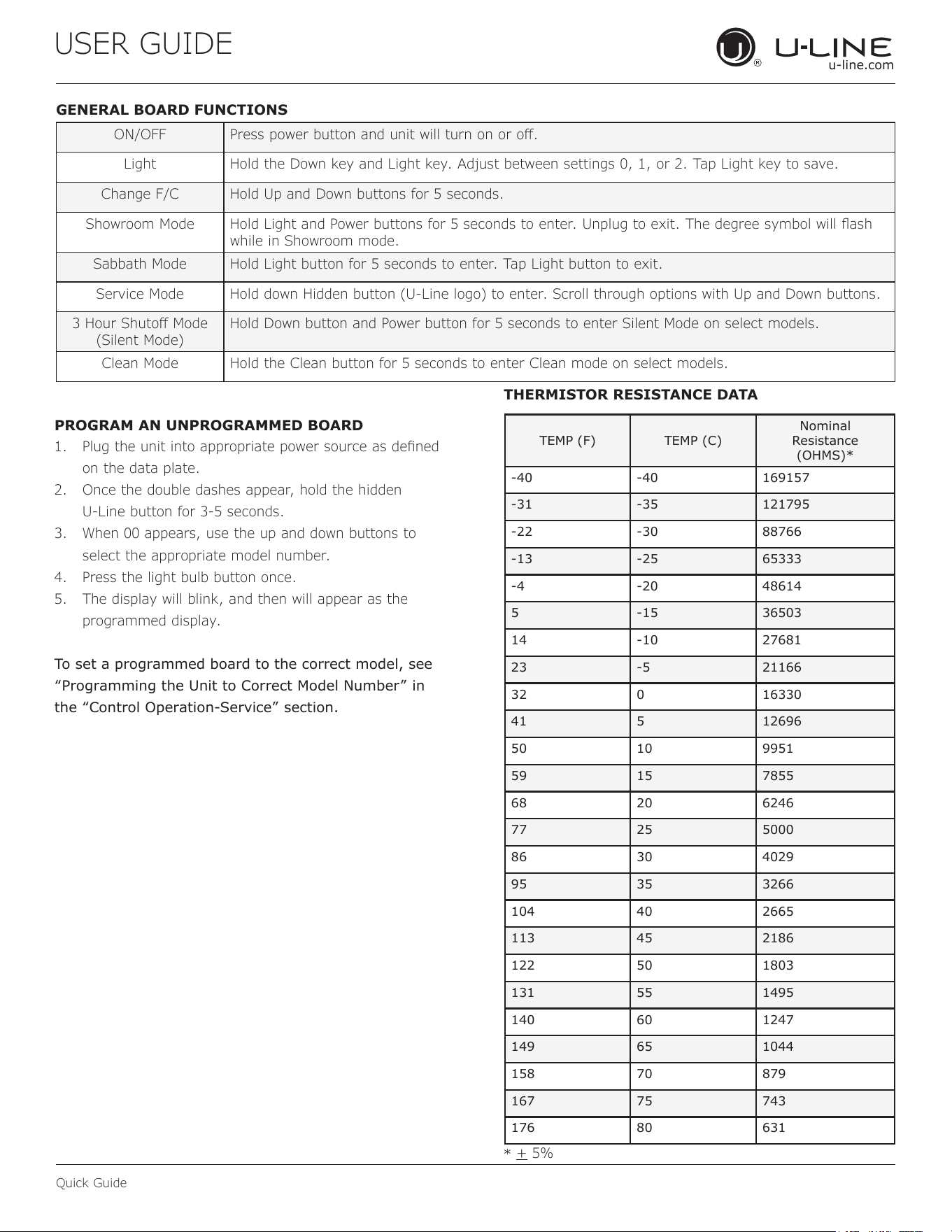
GENERAL BOARD FUNCTIONS
PROGRAM AN UNPROGRAMMED BOARD
THERMISTOR RESISTANCE DATA
ON/OFF Press power button and unit will turn on or o.
Light Hold the Down key and Light key. Adjust between settings 0, 1, or 2. Tap Light key to save.
Change F/C Hold Up and Down buttons for 5 seconds.
Showroom Mode Hold Light and Power buttons for 5 seconds to enter. Unplug to exit. The degree symbol will ash
while in Showroom mode.
Sabbath Mode Hold Light button for 5 seconds to enter. Tap Light button to exit.
Service Mode Hold down Hidden button (U-Line logo) to enter. Scroll through options with Up and Down buttons.
3 Hour Shuto Mode
(Silent Mode)
Hold Down button and Power button for 5 seconds to enter Silent Mode on select models.
Clean Mode Hold the Clean button for 5 seconds to enter Clean mode on select models.
1. Plug the unit into appropriate power source as dened
on the data plate.
2. Once the double dashes appear, hold the hidden
U-Line button for 3-5 seconds.
3. When 00 appears, use the up and down buttons to
select the appropriate model number.
4. Press the light bulb button once.
5. The display will blink, and then will appear as the
programmed display.
Tosetaprogrammedboardtothecorrectmodel,see
“Programming the Unit to Correct Model Number” in
the“ControlOperation-Service”section.
TEMP(F) TEMP(C)
Nominal
Resistance
(OHMS)*
-40 -40 169157
-31 -35 121795
-22 -30 88766
-13 -25 65333
-4 -20 48614
5 -15 36503
14 -10 27681
23 -5 21166
32 0 16330
41 5 12696
50 10 9951
59 15 7855
68 20 6246
77 25 5000
86 30 4029
95 35 3266
104 40 2665
113 45 2186
122 50 1803
131 55 1495
140 60 1247
149 65 1044
158 70 879
167 75 743
176 80 631
*
+ 5%
29
USER GUIDE
u-line.com
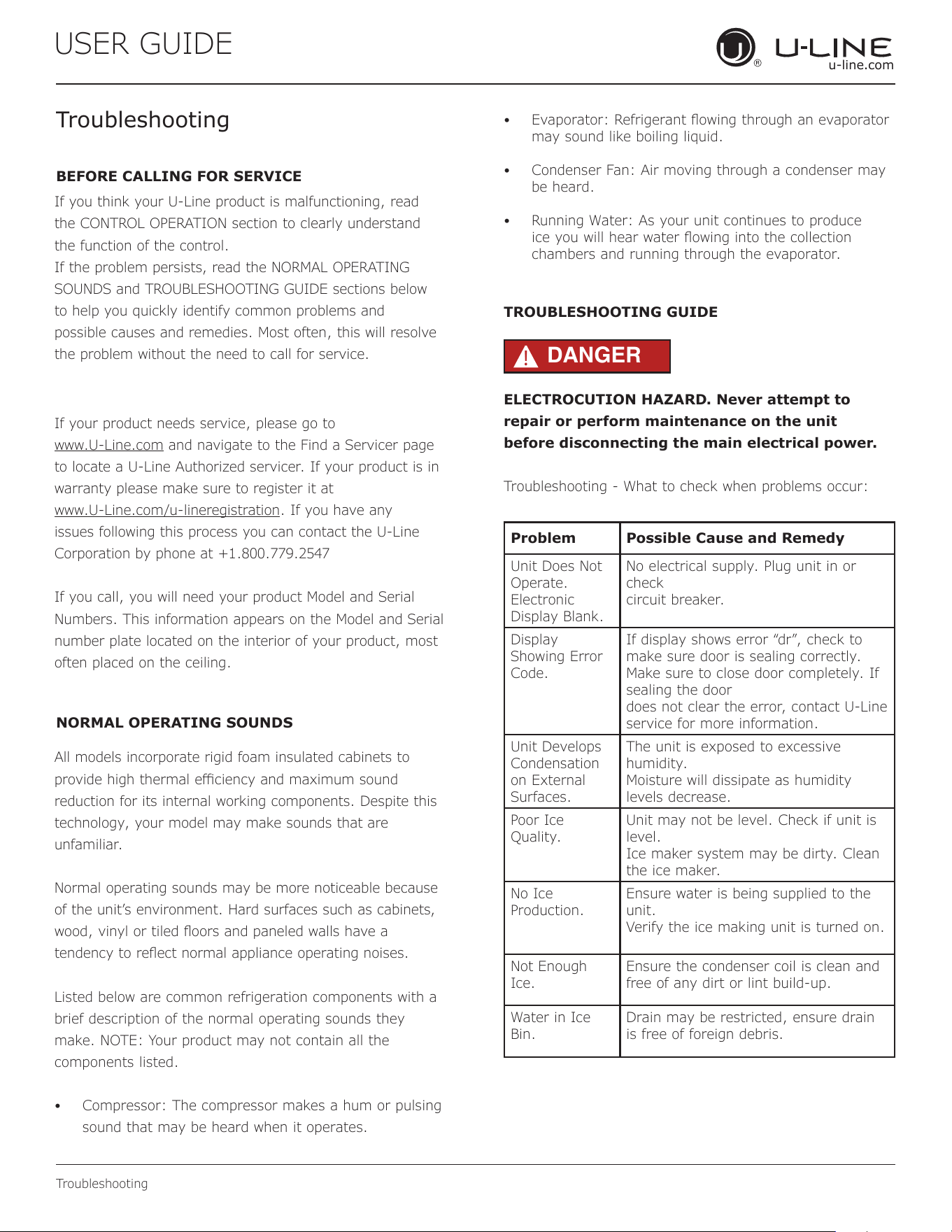
Troubleshooting
If you think your U-Line product is malfunctioning, read
the CONTROL OPERATION section to clearly understand
the function of the control.
If the problem persists, read the NORMAL OPERATING
SOUNDS and TROUBLESHOOTING GUIDE sections below
to help you quickly identify common problems and
possible causes and remedies. Most often, this will resolve
the problem without the need to call for service.
If your product needs service, please go to
www.U-Line.com and navigate to the Find a Servicer page
to locate a U-Line Authorized servicer. If your product is in
warranty please make sure to register it at
www.U-Line.com/u-lineregistration. If you have any
issues following this process you can contact the U-Line
Corporation by phone at +1.800.779.2547
If you call, you will need your product Model and Serial
Numbers. This information appears on the Model and Serial
number plate located on the interior of your product, most
often placed on the ceiling.
All models incorporate rigid foam insulated cabinets to
provide high thermal eciency and maximum sound
reduction for its internal working components. Despite this
technology, your model may make sounds that are
unfamiliar.
Normal operating sounds may be more noticeable because
of the unit’s environment. Hard surfaces such as cabinets,
wood, vinyl or tiled oors and paneled walls have a
tendency to reect normal appliance operating noises.
Listed below are common refrigeration components with a
brief description of the normal operating sounds they
make. NOTE: Your product may not contain all the
components listed.
• Compressor: The compressor makes a hum or pulsing
sound that may be heard when it operates.
BEFORE CALLING FOR SERVICE
TROUBLESHOOTING GUIDE
ELECTROCUTION HAZARD. Never attempt to
repair or perform maintenance on the unit
before disconnecting the main electrical power.
Troubleshooting - What to check when problems occur:
NORMAL OPERATING SOUNDS
Troubleshooting
• Evaporator: Refrigerant owing through an evaporator
may sound like boiling liquid.
• Condenser Fan: Air moving through a condenser may
be heard.
• Running Water: As your unit continues to produce
ice you will hear water owing into the collection
chambers and running through the evaporator.
DANGER
!
Problem Possible Cause and Remedy
Unit Does Not
Operate.
Electronic
Display Blank.
No electrical supply. Plug unit in or
check
circuit breaker.
Display
Showing Error
Code.
If display shows error “dr”, check to
make sure door is sealing correctly.
Make sure to close door completely. If
sealing the door
does not clear the error, contact U-Line
service for more information.
Unit Develops
Condensation
on External
Surfaces.
The unit is exposed to excessive
humidity.
Moisture will dissipate as humidity
levels decrease.
Poor Ice
Quality.
Unit may not be level. Check if unit is
level.
Ice maker system may be dirty. Clean
the ice maker.
No Ice
Production.
Ensure water is being supplied to the
unit.
Verify the ice making unit is turned on.
Not Enough
Ice.
Ensure the condenser coil is clean and
free of any dirt or lint build-up.
Water in Ice
Bin.
Drain may be restricted, ensure drain
is free of foreign debris.
30
USER GUIDE
u-line.com
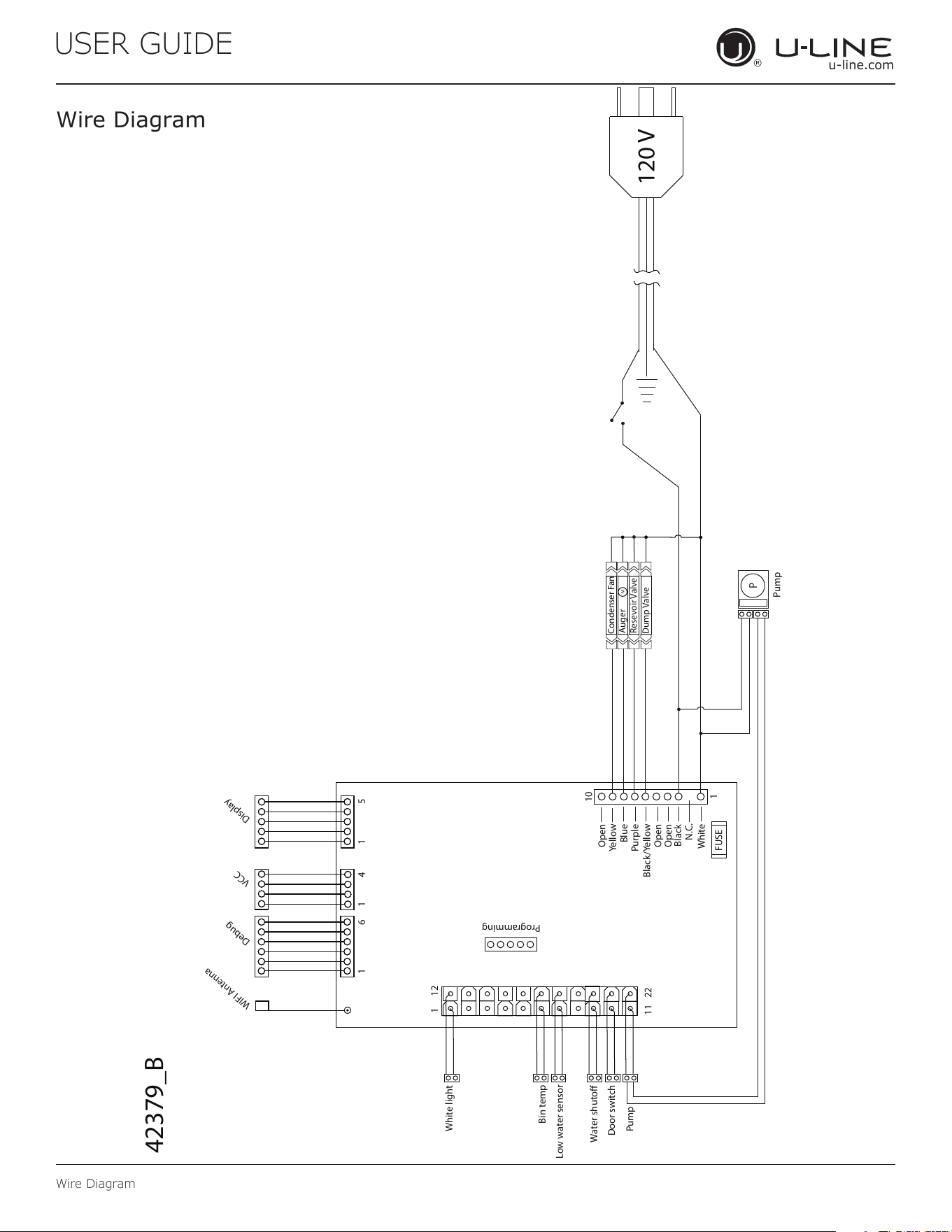
Wire Diagram
Wire Diagram
M
P
120 V
Blue
Yellow
Open
Purple
Black/Yellow
Open
Black
White
FUSE
N.C.
11 22
1
10
1
1 51 6 1 4
12
Pump
White light
Bin temp
Door switch
Pump
Low water sensor
Water shuto
Dump Valve
Resevoir Valve
Auger
Condenser Fan
Open
Programming
Debug
VCC
Display
42379_B
WIFI Antenna
31
USER GUIDE
u-line.com
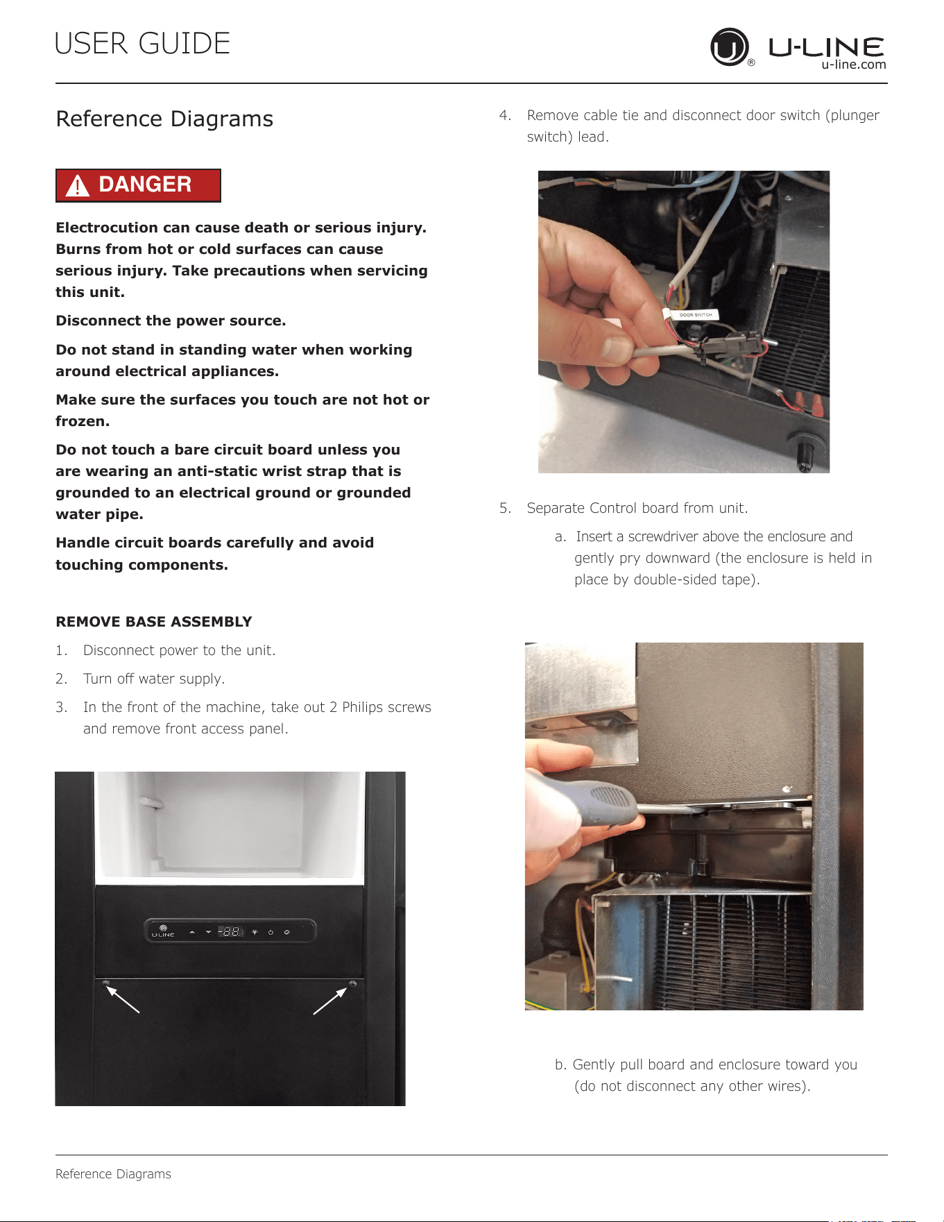
Reference Diagrams
Reference Diagrams
DANGER
!
Electrocution can cause death or serious injury.
Burns from hot or cold surfaces can cause
serious injury. Take precautions when servicing
this unit.
Disconnect the power source.
Do not stand in standing water when working
around electrical appliances.
Make sure the surfaces you touch are not hot or
frozen.
Do not touch a bare circuit board unless you
are wearing an anti-static wrist strap that is
grounded to an electrical ground or grounded
water pipe.
Handle circuit boards carefully and avoid
touching components.
REMOVE BASE ASSEMBLY
1. Disconnect power to the unit.
2. Turn o water supply.
3. In the front of the machine, take out 2 Philips screws
and remove front access panel.
4. Remove cable tie and disconnect door switch (plunger
switch) lead.
5. Separate Control board from unit.
a. Insert a screwdriver above the enclosure and
gently pry downward (the enclosure is held in
place by double-sided tape).
b. Gently pull board and enclosure toward you
(do not disconnect any other wires).
32
USER GUIDE
u-line.com
Reference Diagrams
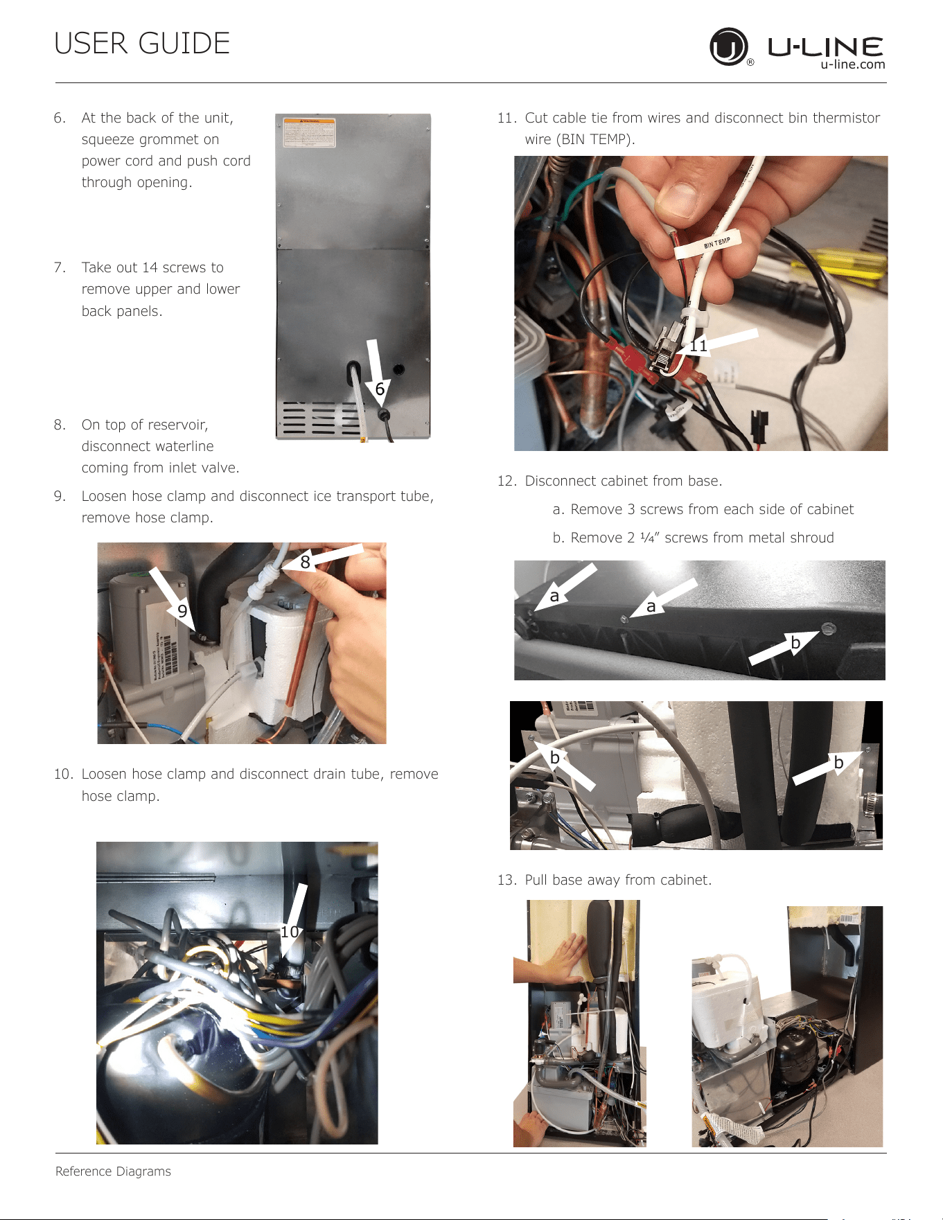
6. At the back of the unit,
squeeze grommet on
power cord and push cord
through opening.
7. Take out 14 screws to
remove upper and lower
back panels.
8. On top of reservoir,
disconnect waterline
coming from inlet valve.
9. Loosen hose clamp and disconnect ice transport tube,
remove hose clamp.
10. Loosen hose clamp and disconnect drain tube, remove
hose clamp.
11. Cut cable tie from wires and disconnect bin thermistor
wire (BIN TEMP).
12. Disconnect cabinet from base.
a. Remove 3 screws from each side of cabinet
b. Remove 2 1⁄4” screws from metal shroud
13. Pull base away from cabinet.
9
8
10
11
a
a
b
b
b
33
USER GUIDE
u-line.com
Reference Diagrams
Reference Diagrams
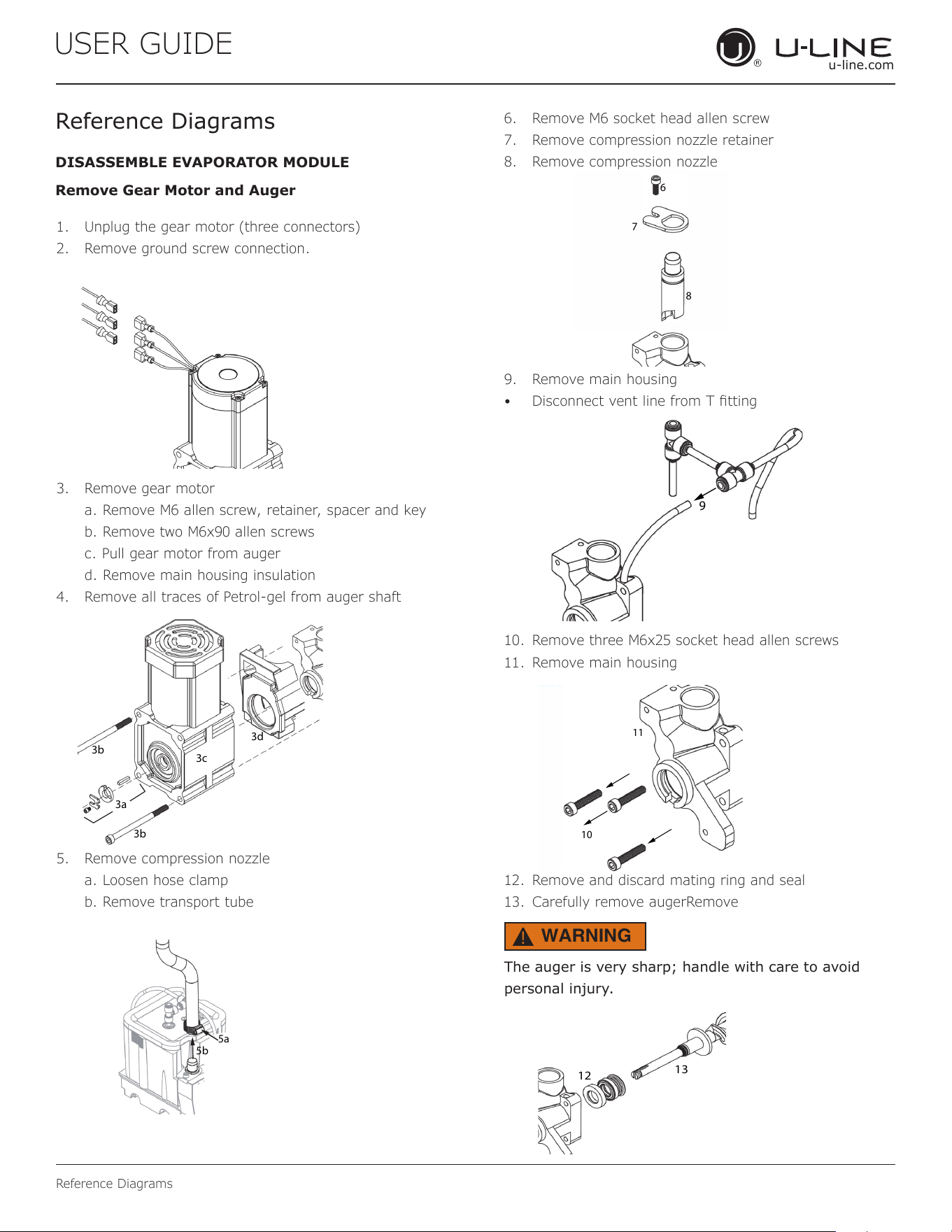
1. Unplug the gear motor (three connectors)
2. Remove ground screw connection.
3. Remove gear motor
a. Remove M6 allen screw, retainer, spacer and key
b. Remove two M6x90 allen screws
c. Pull gear motor from auger
d. Remove main housing insulation
4. Remove all traces of Petrol-gel from auger shaft
5. Remove compression nozzle
a. Loosen hose clamp
b. Remove transport tube
6. Remove M6 socket head allen screw
7. Remove compression nozzle retainer
8. Remove compression nozzle
9. Remove main housing
• Disconnect vent line from T tting
10. Remove three M6x25 socket head allen screws
11. Remove main housing
12. Remove and discard mating ring and seal
13. Carefully remove augerRemove
The auger is very sharp; handle with care to avoid
personal injury.
DISASSEMBLE EVAPORATOR MODULE
Remove Gear Motor and Auger
3a
3b
3c
3d
3b
5a
5b
6
7
8
9
10
11
12
13
WARNING
!
34
USER GUIDE
u-line.com
Reference Diagrams
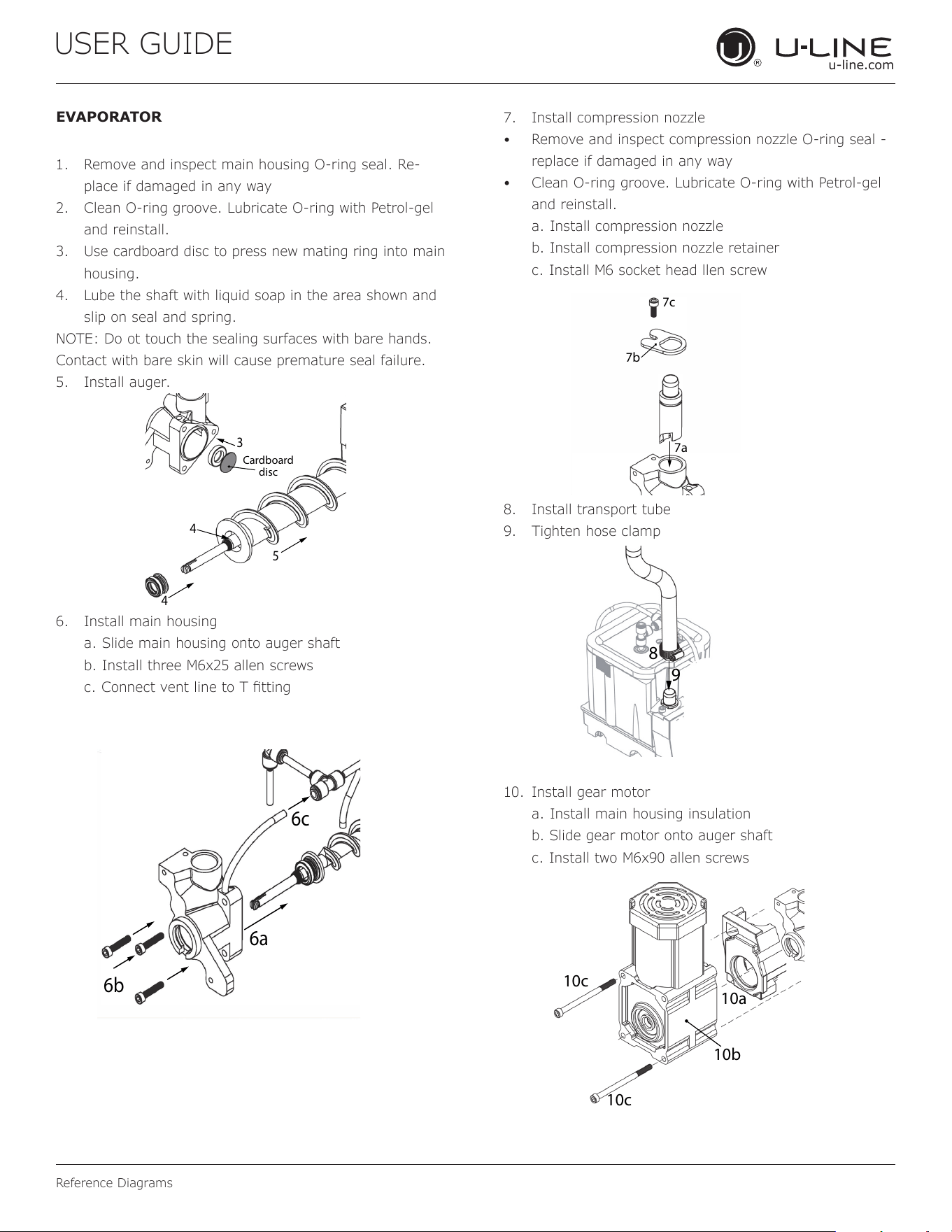
EVAPORATOR
1. Remove and inspect main housing O-ring seal. Re-
place if damaged in any way
2. Clean O-ring groove. Lubricate O-ring with Petrol-gel
and reinstall.
3. Use cardboard disc to press new mating ring into main
housing.
4. Lube the shaft with liquid soap in the area shown and
slip on seal and spring.
NOTE: Do ot touch the sealing surfaces with bare hands.
Contact with bare skin will cause premature seal failure.
5. Install auger.
6. Install main housing
a. Slide main housing onto auger shaft
b. Install three M6x25 allen screws
c. Connect vent line to T tting
7. Install compression nozzle
• Remove and inspect compression nozzle O-ring seal -
replace if damaged in any way
• Clean O-ring groove. Lubricate O-ring with Petrol-gel
and reinstall.
a. Install compression nozzle
b. Install compression nozzle retainer
c. Install M6 socket head llen screw
8. Install transport tube
9. Tighten hose clamp
10. Install gear motor
a. Install main housing insulation
b. Slide gear motor onto auger shaft
c. Install two M6x90 allen screws
3
4
4
5
Cardboard
disc
6a
6b
6c
7b
7a
7c
8
9
10c
10c
10a
10b
35
USER GUIDE
u-line.com
Reference Diagrams
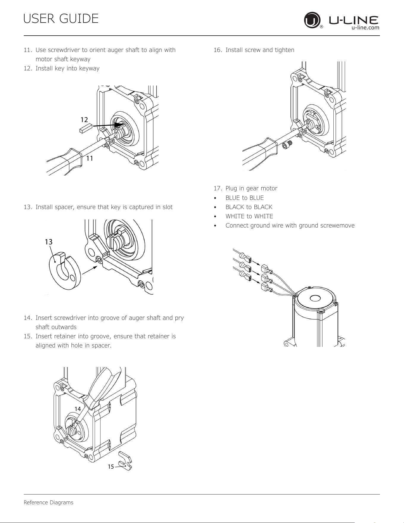
11. Use screwdriver to orient auger shaft to align with
motor shaft keyway
12. Install key into keyway
13. Install spacer, ensure that key is captured in slot
14. Insert screwdriver into groove of auger shaft and pry
shaft outwards
15. Insert retainer into groove, ensure that retainer is
aligned with hole in spacer.
16. Install screw and tighten
17. Plug in gear motor
• BLUE to BLUE
• BLACK to BLACK
• WHITE to WHITE
• Connect ground wire with ground screwemove
14
15
11
12
13
36
USER GUIDE
u-line.com
Product Liability
Product Liability
Field service technicians are authorized to make an initial
assessment in the event of reported damages. If there are
any questions about the process involved, the technician
shou
ld call U-Line for further explanation.
While inspecting for defects or installation issues, photos
should be taken to document any damages or issues found.
During the assessment, if the service technician is able to
nd the source of the damage and it can be resolved by
replacement of a part, the servicer is authorized to replace
the part in question. The part that caused the damage
must be returned to U-Line in its entirety. The part must
be clearly labeled with the serial number of the unit it was
removed from, the date, and the servicer who removed the
part.
If the service technician determines the damage is the
result of installation issues (water connection/drain, etc.),
the consumer would be notied and the issues shall be
resolved at the direction of the consumer.
If damage is evident and the service technician is
unable to nd the source, U-Line must be contacted at
1.800.799.2547 for further direction.
8900 N. 55th Street • Milwaukee, WI 53223
T: +1.414.354.0300 • F: +1.414.354.5696
Website: www.u-line.com
Right product. Right place.
Right temperature Since 1962.
37
USER GUIDE
u-line.com
Warranty Claims
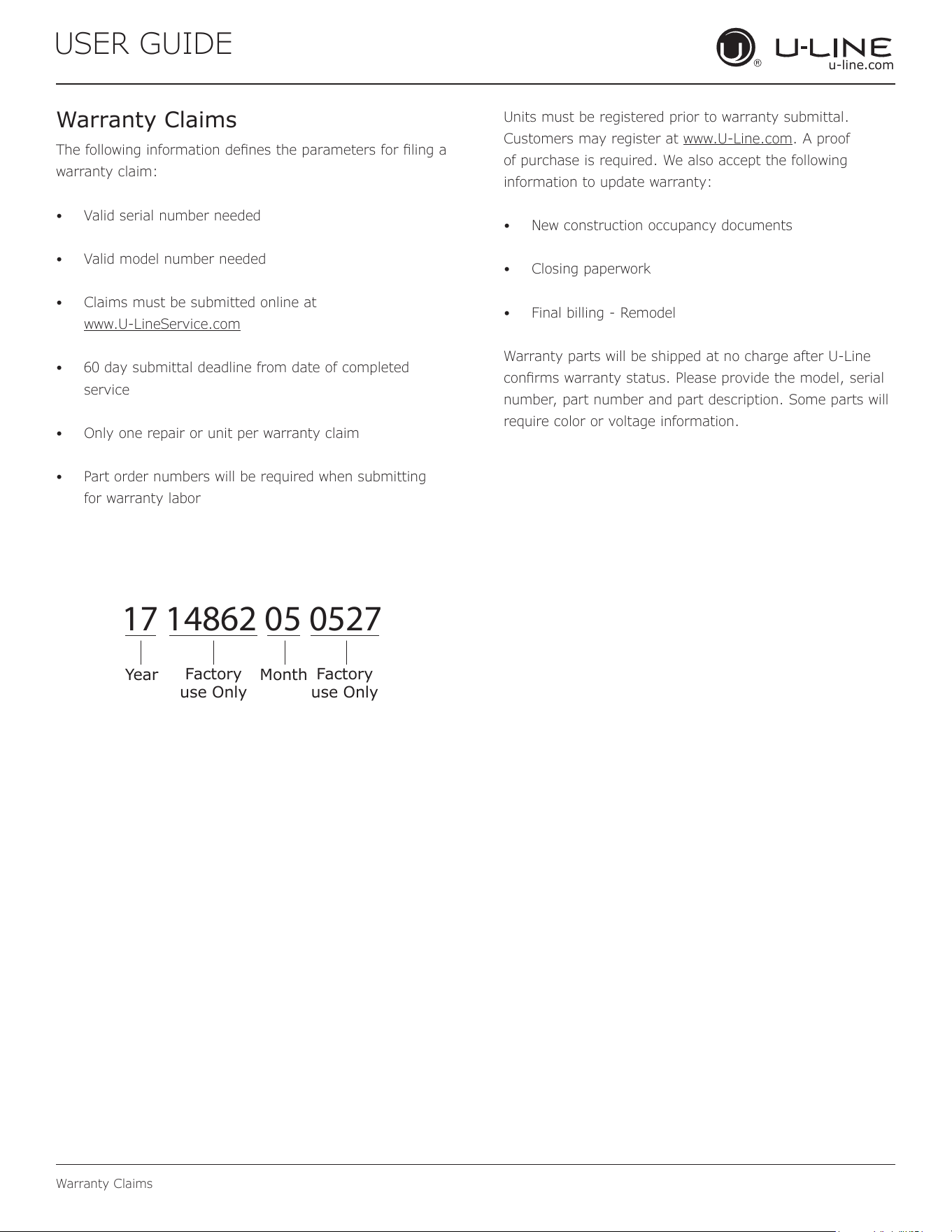
The following information denes the parameters for ling a
warranty claim:
• Valid serial number needed
• Valid model number needed
• Claims must be submitted online at
www.U-LineService.com
• 60 day submittal deadline from date of completed
service
• Only one repair or unit per warranty claim
• Part order numbers will be required when submitting
for warranty labor
Units must be registered prior to warranty submittal.
Customers may register at www.U-Line.com. A proof
of purchase is required. We also accept the following
information to update warranty:
• New construction occupancy documents
• Closing paperwork
• Final billing - Remodel
Warranty parts will be shipped at no charge after U-Line
conrms warranty status. Please provide the model, serial
number, part number and part description. Some parts will
require color or voltage information.
Warranty Claims
17 14862 05 0527
Year
Factory
use Only
Factory
use Only
Month
38
USER GUIDE
u-line.com
Parts
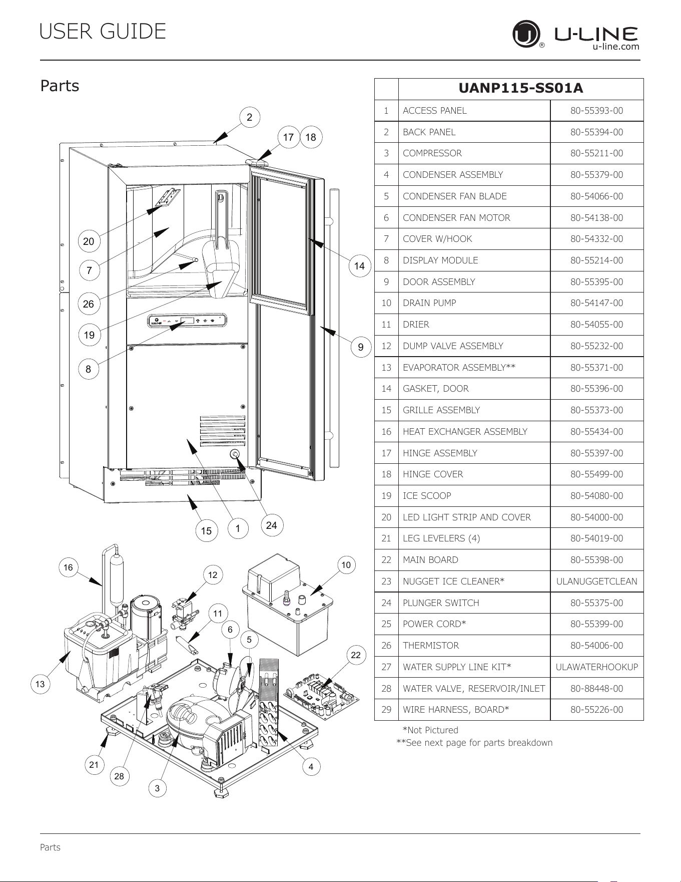
Pa rts
UANP115-SS01A
1 ACCESS PANEL 80-55393-00
2 BACK PANEL 80-55394-00
3 COMPRESSOR 80-55211-00
4 CONDENSER ASSEMBLY 80-55379-00
5 CONDENSER FAN BLADE 80-54066-00
6 CONDENSER FAN MOTOR 80-54138-00
7 COVER W/HOOK 80-54332-00
8 DISPLAY MODULE 80-55214-00
9 DOOR ASSEMBLY 80-55395-00
10 DRAIN PUMP 80-54147-00
11 DRIER 80-54055-00
12 DUMP VALVE ASSEMBLY 80-55232-00
13 EVAPORATOR ASSEMBLY** 80-55371-00
14 GASKET, DOOR 80-55396-00
15 GRILLE ASSEMBLY 80-55373-00
16 HEAT EXCHANGER ASSEMBLY 80-55434-00
17 HINGE ASSEMBLY 80-55397-00
18 HINGE COVER 80-55499-00
19 ICE SCOOP 80-54080-00
20 LED LIGHT STRIP AND COVER 80-54000-00
21 LEG LEVELERS (4) 80-54019-00
22 MAIN BOARD 80-55398-00
23 NUGGET ICE CLEANER* ULANUGGETCLEAN
24 PLUNGER SWITCH 80-55375-00
25 POWER CORD* 80-55399-00
26 THERMISTOR 80-54006-00
27 WATER SUPPLY LINE KIT* ULAWATERHOOKUP
28 WATER VALVE, RESERVOIR/INLET 80-88448-00
29 WIRE HARNESS, BOARD* 80-55226-00
17 18
2
14
9
24
1
15
20
7
26
19
8
5
11
12
13
16
21
28
3
4
10
22
6
*Not Pictured
**See next page for parts breakdown
39
USER GUIDE
u-line.com
Parts
6
4
3
1
9
5
2
14
13
13
10
11
12
8
7
15
16
16
16
16
16
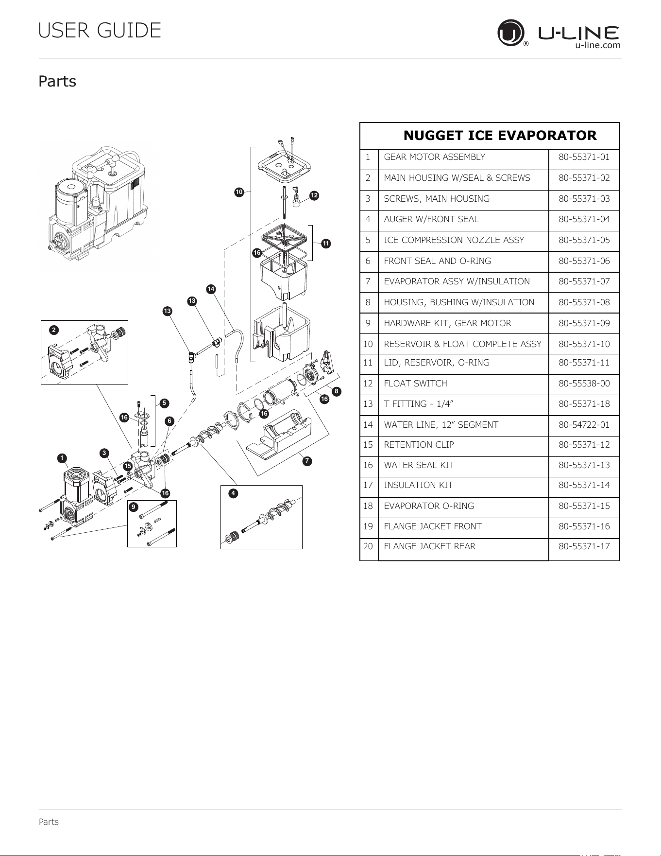
NUGGET ICE EVAPORATOR
1 GEAR MOTOR ASSEMBLY 80-55371-01
2 MAIN HOUSING W/SEAL & SCREWS 80-55371-02
3 SCREWS, MAIN HOUSING 80-55371-03
4 AUGER W/FRONT SEAL 80-55371-04
5 ICE COMPRESSION NOZZLE ASSY 80-55371-05
6 FRONT SEAL AND O-RING 80-55371-06
7 EVAPORATOR ASSY W/INSULATION 80-55371-07
8 HOUSING, BUSHING W/INSULATION 80-55371-08
9 HARDWARE KIT, GEAR MOTOR 80-55371-09
10 RESERVOIR & FLOAT COMPLETE ASSY 80-55371-10
11 LID, RESERVOIR, O-RING 80-55371-11
12 FLOAT SWITCH 80-55538-00
13 T FITTING - 1/4” 80-55371-18
14 WATER LINE, 12” SEGMENT 80-54722-01
15 RETENTION CLIP 80-55371-12
16 WATER SEAL KIT 80-55371-13
17 INSULATION KIT 80-55371-14
18 EVAPORATOR O-RING 80-55371-15
19 FLANGE JACKET FRONT
80-55371-16
20 FLANGE JACKET REAR 80-55371-17
Pa rts
40
USER GUIDE
u-line.com
Ordering Replacement Parts
Parts may be ordered online at www.U-Line.com
See our contact information below:
www.U-LineService.com (with service login)
Phone Number: +1.800.779.2547
NOTICE
Use only genuine U-Line replacement parts.
The use of non-U-Line parts can reduce speed
of ice production, cause water to overow from
ice maker mold, damage the unit, and void the
warranty.
Warranty parts will be shipped at no charge after U-Line
conrms warranty status. Please provide the model, serial
number, part number and part description. Some parts will
require color or voltage information.
If U-Line requires the return of original parts, we will
inform you when the parts order is taken. This
requirement will be noted on your packing list. A
prepaid shipping label will be emailed to you. Please
enclose a copy of the parts packing list and be sure the
model and serial numbers are legible on the paperwork.
Tag the part with the reported defect.
Customers and non-authorized servicers may order non-
warranty parts at www.u-line.com. Authorized servicers
with a servicer login may order non-warranty parts at
www.u-lineservice.com.
Ordering Replacement Parts
41
USER GUIDE
u-line.com
R-600A Specications
USER GUIDE
R-600A Specifications 1
u-line.com
SAFETY • INSTALLATION & INTEGRATION • OPERATING INSTRUCTIONS • MAINTENANCE • SERVICE
R-600A Specifications
For R-600a refrigerant service tips and more videos, go
to: www.u-line.com/videos
.
WARNING
!
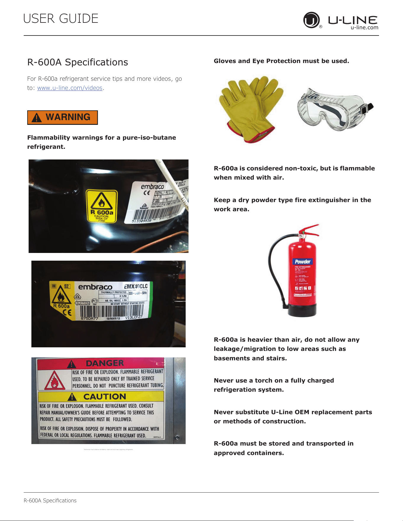
Flammability warnings for a pure-iso-butane
refrigerant.
Technician m ust observe al l federal, st ate and local la ws regarding r efrigerants .
Gloves and Eye Protection must be used.
R-600a is considered non-toxic, but is flammable
when mixed with air.
Keep a dry powder type fire extinguisher in the
work area.
R-600a is heavier than air, do not allow any
leakage/migration to low areas such as
basements and stairs.
Never use a torch on a fully charged
refrigeration system.
Never substitute U-Line OEM replacement parts
or methods of construction.
R-600a must be stored and transported in
approved containers.
42
R-600A Specications
USER GUIDE
u-line.com
USER GUIDE
R-600A Specifications 2
u-line.com
SAFETY • INSTALLATION & INTEGRATION • OPERATING INSTRUCTIONS • MAINTENANCE • SERVICE
WARNING
!
Only skilled and well trained service technicians
permitted to service R-600a equipped products.
All tools and equipment must be approved for
use with R-600a refrigerant.
Local, state and federal laws, standards must be
observed along with proper certification and
licensing.
Ventilation is required during servicing.
No conversions to R-600a from any other
refrigerants. OEM R-600a equipped unit only.
Service area must be free of ignition sources.
No smoking is allowed in the service area.
All replacement electrical components must be
OEM and installed properly (sealed and
covered).
If the evaporator is cold prior to service, it must
be thawed prior to service.
When using a vacuum pump, start pump before
opening refrigeration system.
Vacuum pump and recovery equipment should
be at least 10 feet from the work area.
It is recommended that a simple LPG gas
detector is on site during service.
Ensure that all R-600a is removed from the
system prior to brazing any part of the sealed
system.
Only a clean, dry leak free system should be
charged with R-600a.
R-600A SPECIFICATIONS/LABELING
R-600a equipped products are labeled (both the unit and
the compressor).
R-600a is colorless and odorless.
R-600a is considered non-toxic, but is flammable when
mixed with air.
Do not remove or alter any R-600a labeling on the
product.
Use only a refrigerant grade R-600a from a properly
labeled container.
RECOVERING/RECLAIMING R-600A
(R-600a has been exempted from recovery/reclaiming
requirements by the US EPA)
Recovery/Reclaiming equipment must be approved for use
with R-600a.
Ensure the evaporator is at room temperature prior to
recovery/reclaiming R-600a.
Use a common piercing pliers or piercing valve to remove
R-600a from the compressor process tube. (Note: Piercing
devices must not be left on the system and must be
replaced with a Schrader type valve.)
43
USER GUIDE
u-line.com
R-600A Specications
USER GUIDE
R-600A Specifications 3
u-line.com
SAFETY • INSTALLATION & INTEGRATION • OPERATING INSTRUCTIONS • MAINTENANCE • SERVICE
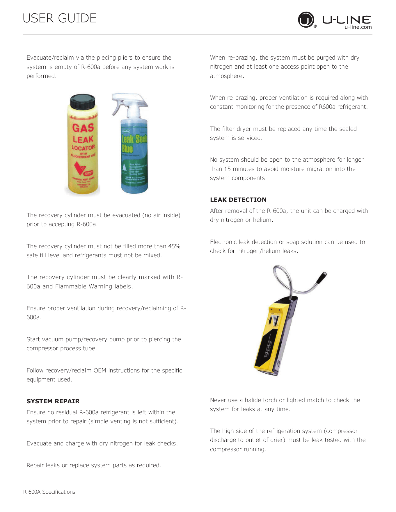
Evacuate/reclaim via the piecing pliers to ensure the
system is empty of R-600a before any system work is
performed.
The recovery cylinder must be evacuated (no air inside)
prior to accepting R-600a.
The recovery cylinder must not be filled more than 45%
safe fill level and refrigerants must not be mixed.
The recovery cylinder must be clearly marked with R-
600a and Flammable Warning labels.
Ensure proper ventilation during recovery/reclaiming of R-
600a.
Start vacuum pump/recovery pump prior to piercing the
compressor process tube.
Follow recovery/reclaim OEM instructions for the specific
equipment used.
SYSTEM REPAIR
Ensure no residual R-600a refrigerant is left within the
system prior to repair (simple venting is not sufficient).
Evacuate and charge with dry nitrogen for leak checks.
Repair leaks or replace system parts as required.
When re-brazing, the system must be purged with dry
nitrogen and at least one access point open to the
atmosphere.
When re-brazing, proper ventilation is required along with
constant monitoring for the presence of R600a refrigerant.
The filter dryer must be replaced any time the sealed
system is serviced.
No system should be open to the atmosphere for longer
than 15 minutes to avoid moisture migration into the
system components.
LEAK DETECTION
After removal of the R-600a, the unit can be charged with
dry nitrogen or helium.
Electronic leak detection or soap solution can be used to
check for nitrogen/helium leaks.
Never use a halide torch or lighted match to check the
system for leaks at any time.
The high side of the refrigeration system (compressor
discharge to outlet of drier) must be leak tested with the
compressor running.
44
R-600A Specications
USER GUIDE
u-line.com
USER GUIDE
R-600A Specifications 4
u-line.com
SAFETY • INSTALLATION & INTEGRATION • OPERATING INSTRUCTIONS • MAINTENANCE • SERVICE
The low side of the refrigeration system (evaporator,
compressor and suction line) must be leak tested with the
compressor off (equalized pressure).
RECHARGING
No air is ever to be allowed inside the refrigeration system
(R-600a refrigerant or dry nitrogen only).
Never use a torch on a fully charged refrigeration system.
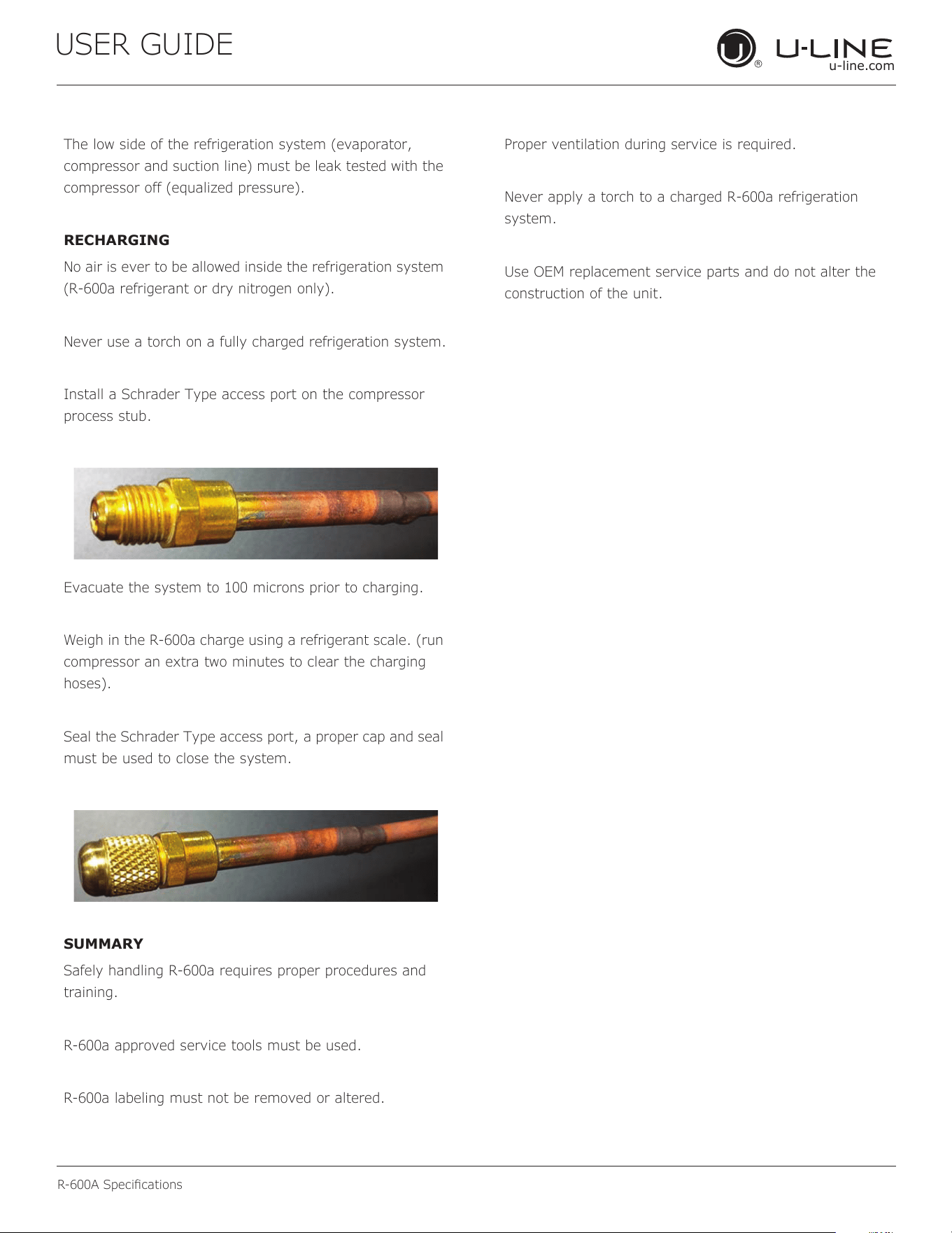
Install a Schrader Type access port on the compressor
process stub.
Evacuate the system to 100 microns prior to charging.
Weigh in the R-600a charge using a refrigerant scale. (run
compressor an extra two minutes to clear the charging
hoses).
Seal the Schrader Type access port, a proper cap and seal
must be used to close the system.
SUMMARY
Safely handling R-600a requires proper procedures and
training.
R-600a approved service tools must be used.
R-600a labeling must not be removed or altered.
Proper ventilation during service is required.
Never apply a torch to a charged R-600a refrigeration
system.
Use OEM replacement service parts and do not alter the
construction of the unit.
45
USER GUIDE
u-line.com
System Diagnosis Guide
System Diagnosis Guide
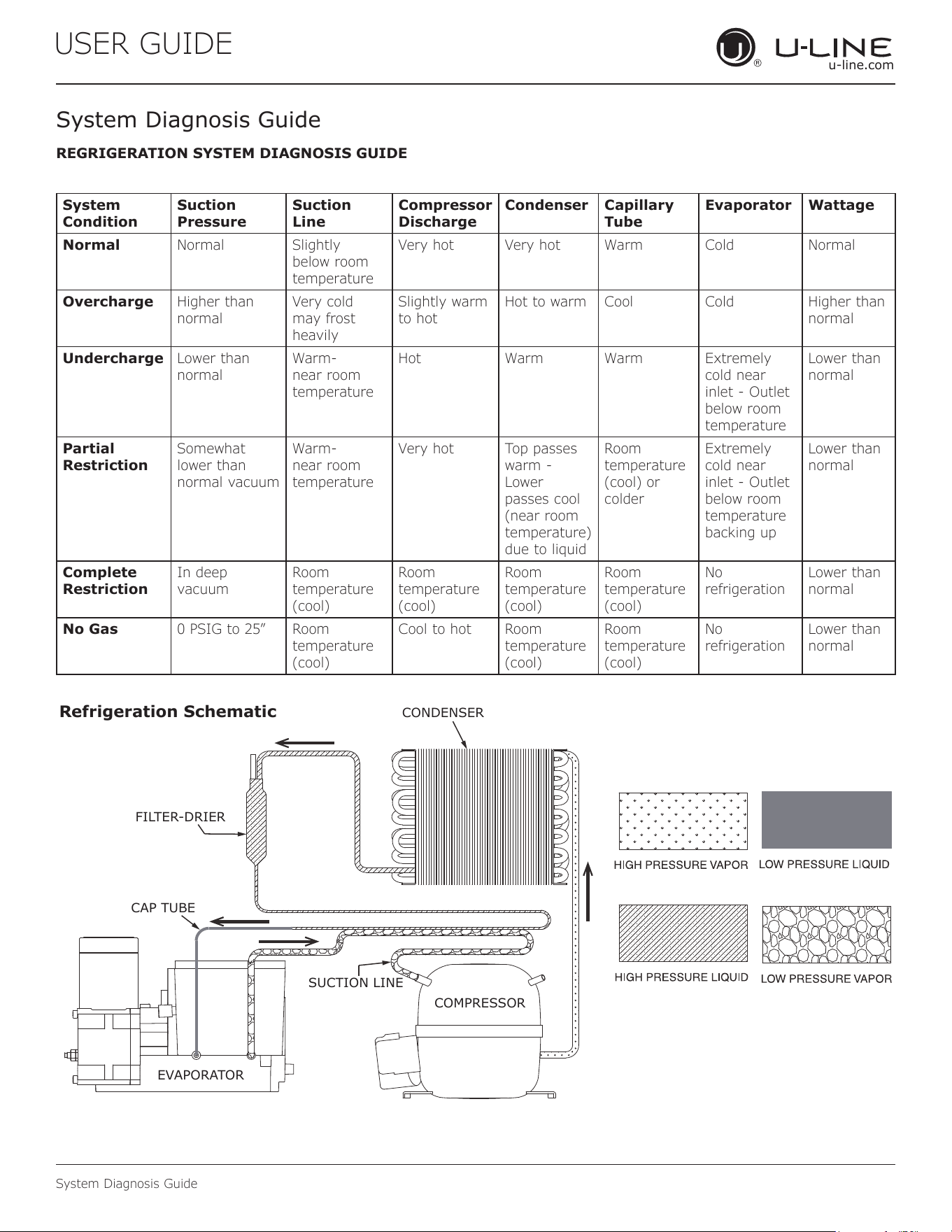
REGRIGERATION SYSTEM DIAGNOSIS GUIDE
System
Condition
Suction
Pressure
Suction
Line
Compressor
Discharge
Condenser Capillary
Tube
Evaporator Wattage
Normal Normal Slightly
below room
temperature
Very hot Very hot Warm Cold Normal
Overcharge Higher than
normal
Very cold
may frost
heavily
Slightly warm
to hot
Hot to warm Cool Cold Higher than
normal
Undercharge Lower than
normal
Warm-
near room
temperature
Hot Warm Warm Extremely
cold near
inlet - Outlet
below room
temperature
Lower than
normal
Partial
Restriction
Somewhat
lower than
normal vacuum
Warm-
near room
temperature
Very hot Top passes
warm -
Lower
passes cool
(near room
temperature)
due to liquid
Room
temperature
(cool) or
colder
Extremely
cold near
inlet - Outlet
below room
temperature
backing up
Lower than
normal
Complete
Restriction
In deep
vacuum
Room
temperature
(cool)
Room
temperature
(cool)
Room
temperature
(cool)
Room
temperature
(cool)
No
refrigeration
Lower than
normal
No Gas 0 PSIG to 25” Room
temperature
(cool)
Cool to hot Room
temperature
(cool)
Room
temperature
(cool)
No
refrigeration
Lower than
normal
CONDENSER
Refrigeration Schematic
CAP TUBE
SUCTION LINE
EVAPORATOR
COMPRESSOR
FILTER-DRIER
46
USER GUIDE
u-line.com
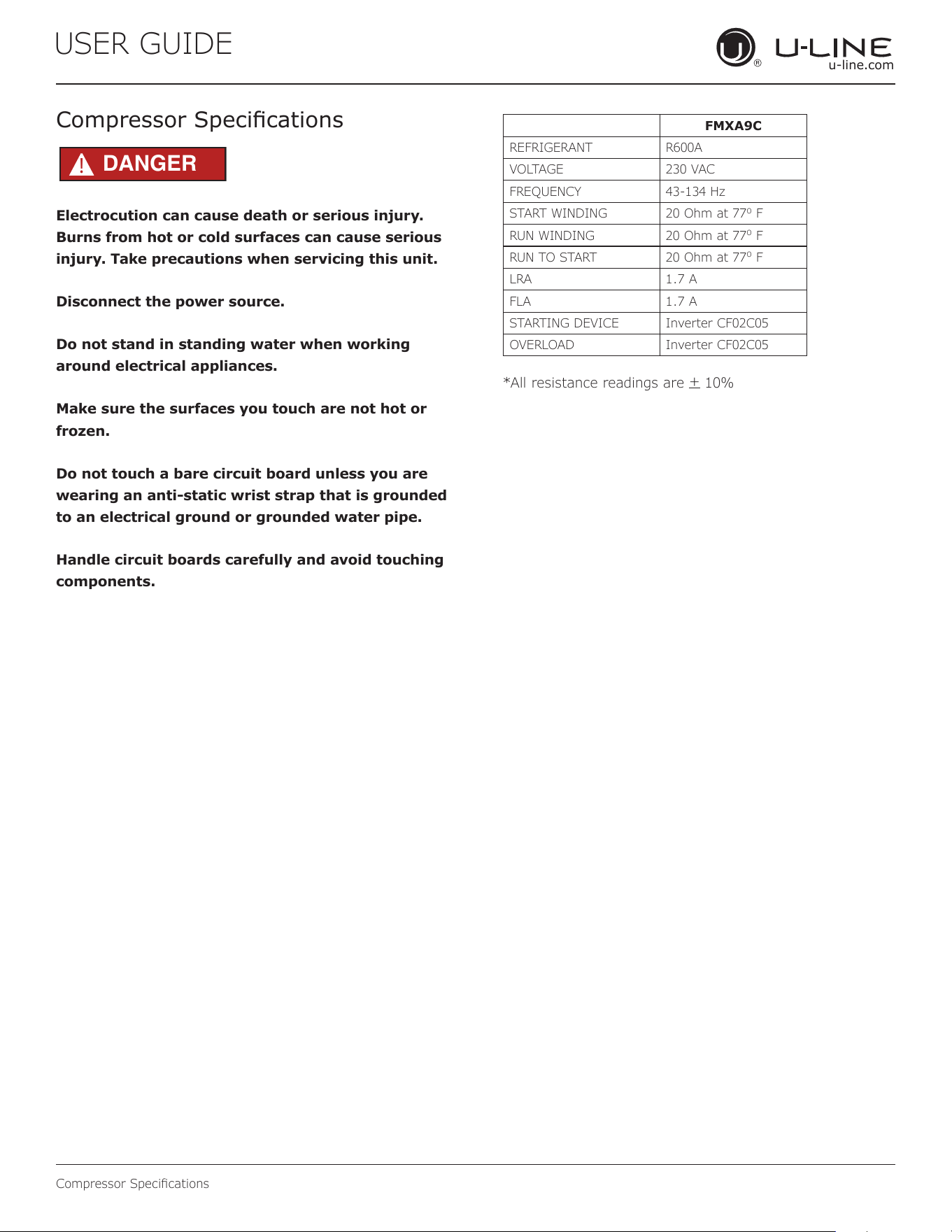
Compressor Specications
Electrocution can cause death or serious injury.
Burns from hot or cold surfaces can cause serious
injury. Take precautions when servicing this unit.
Disconnect the power source.
Do not stand in standing water when working
around electrical appliances.
Make sure the surfaces you touch are not hot or
frozen.
Do not touch a bare circuit board unless you are
wearing an anti-static wrist strap that is grounded
to an electrical ground or grounded water pipe.
Handle circuit boards carefully and avoid touching
components.
Compressor Specications
FMXA9C
REFRIGERANT R600A
VOLTAGE 230 VAC
FREQUENCY 43-134 Hz
START WINDING 20 Ohm at 77
o
F
RUN WINDING 20 Ohm at 77
o
F
RUN TO START 20 Ohm at 77
o
F
LRA 1.7 A
FLA 1.7 A
STARTING DEVICE Inverter CF02C05
OVERLOAD Inverter CF02C05
*All resistance readings are
+
10%
DANGER
!
47
USER GUIDE
u-line.com
Troubleshooting Extended
Troubleshooting - Extended
SPECIFIC ERRORS AND ISSUES
The advanced diagnostic capabilities of the electronic
controls utilized on the 1, 3, and 5 Class units allow for
easy and thorough troubleshooting.
Navigation of the control is the key and is explained in
the CONTROL OPERATION section of the manual, along
with control button layout, control function descriptions,
a service mode menu and service menu selection
explanations.
Verication of temperature and thermistor performance can
be identied by directly viewing thermistor readings in the
service mode.
Component failure issues can be identied through
service mode menu #20, “Component Testing.” Individual
components can be switched on and o to check for both
proper function of a specic component and also delivery of
supply voltage to the components through the relays and
DC outputs located on the relay/power board.
Included in this section are some diagnostic tips and of
course, if additional help is required, please contact the
U-Line Corp, “Customer Care Facility” at +1.800.779.2547
for assistance.
NORMAL OPERATING SOUNDS
All models incorporate rigid foam insulated cabinets to
provide high thermal eciency and maximum sound
reduction for its internal working components. Despite
this technology, your model may make sounds that are
unfamiliar.
Normal operating sounds may be more noticeable because
of the unit’s environment. Hard surfaces such as cabinets,
wood, vinyl or tiled oors and paneled walls have a
tendency to reect normal appliance operating noises.
Listed below are common refrigeration components with a
brief description of the normal sounds they make. NOTE:
Your product may not contain all the components listed.
• Compressor: The compressor makes a hum or pulsing
sound that may be heard when it operates.
• Evaporator: Refrigerant owing through an evaporator
may sound like boiling liquid.
• Condenser Fan: Air moving through a condenser may
be heard.
• Water Valve: Running water and clicking as valve
opens and closes.
• Ice Dropping: Ice falling into the bin makes a dull thud
sound. The sound decreases as the bin lls with ice.
• Solenoid Valves: An occasional clicking sound may be
heard as solenoid valves are operated.
48
USER GUIDE
u-line.com
Troubleshooting Extended
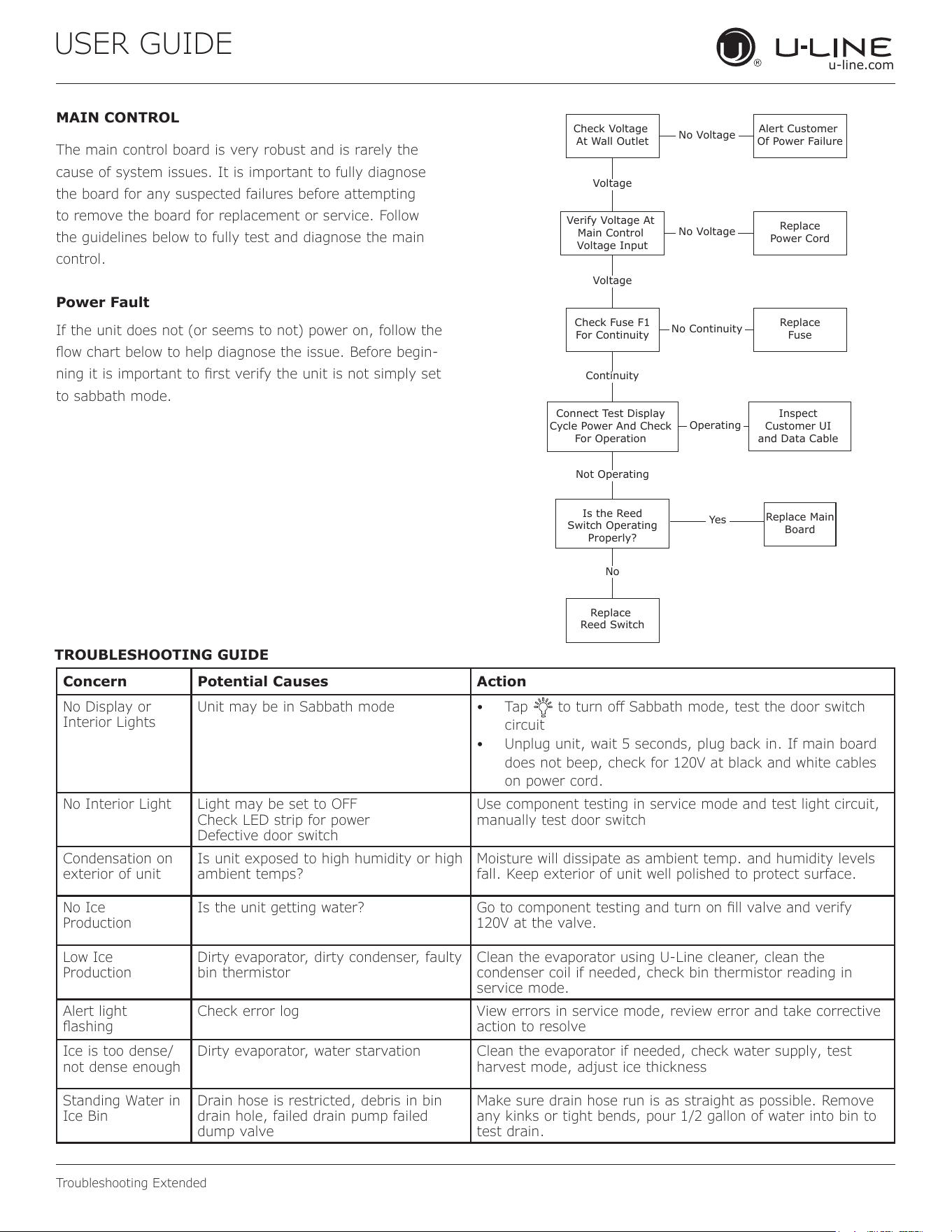
MAIN CONTROL
The main control board is very robust and is rarely the
cause of system issues. It is important to fully diagnose
the board for any suspected failures before attempting
to remove the board for replacement or service. Follow
the guidelines below to fully test and diagnose the main
control.
Power Fault
If the unit does not (or seems to not) power on, follow the
ow chart below to help diagnose the issue. Before begin-
ning it is important to rst verify the unit is not simply set
to sabbath mode.
Check Voltage
At Wall Outlet
Verify Voltage At
Main Control
Voltage Input
Check Fuse F1
For Continuity
Replace
Reed Switch
Replace Main
Board
Replace
Fuse
Replace
Power Cord
Alert Customer
Of Power Failure
Is the Reed
Switch Operating
Properly?
Inspect
Customer UI
and Data Cable
Connect Test Display
Cycle Power And Check
For Operation
No Voltage
No Voltage
Voltage
Continuity
Operating
Not Operating
No Continuity
No
Yes
Voltage
TROUBLESHOOTING GUIDE
Concern Potential Causes Action
No Display or
Interior Lights
Unit may be in Sabbath mode • Tap to turn o Sabbath mode, test the door switch
circuit
• Unplug unit, wait 5 seconds, plug back in. If main board
does not beep, check for 120V at black and white cables
on power cord.
No Interior Light Light may be set to OFF
Check LED strip for power
Defective door switch
Use component testing in service mode and test light circuit,
manually test door switch
Condensation on
exterior of unit
Is unit exposed to high humidity or high
ambient temps?
Moisture will dissipate as ambient temp. and humidity levels
fall. Keep exterior of unit well polished to protect surface.
No Ice
Production
Is the unit getting water? Go to component testing and turn on ll valve and verify
120V at the valve.
Low Ice
Production
Dirty evaporator, dirty condenser, faulty
bin thermistor
Clean the evaporator using U-Line cleaner, clean the
condenser coil if needed, check bin thermistor reading in
service mode.
Alert light
ashing
Check error log View errors in service mode, review error and take corrective
action to resolve
Ice is too dense/
not dense enough
Dirty evaporator, water starvation Clean the evaporator if needed, check water supply, test
harvest mode, adjust ice thickness
Standing Water in
Ice Bin
Drain hose is restricted, debris in bin
drain hole, failed drain pump failed
dump valve
Make sure drain hose run is as straight as possible. Remove
any kinks or tight bends, pour 1/2 gallon of water into bin to
test drain.
49
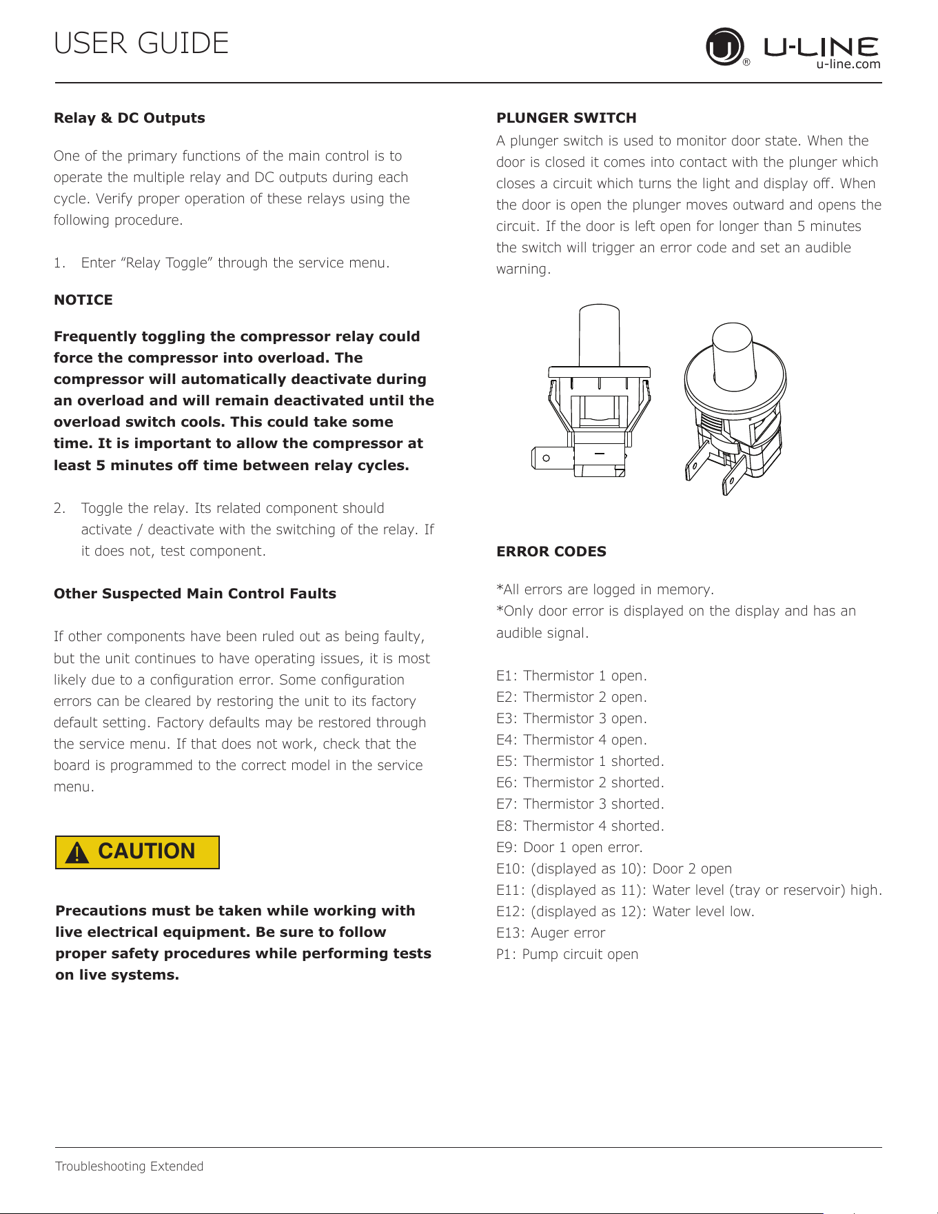
USER GUIDE
u-line.com
Troubleshooting Extended
Relay & DC Outputs
One of the primary functions of the main control is to
operate the multiple relay and DC outputs during each
cycle. Verify proper operation of these relays using the
following procedure.
1. Enter “Relay Toggle” through the service menu.
NOTICE
Frequently toggling the compressor relay could
force the compressor into overload. The
compressor will automatically deactivate during
an overload and will remain deactivated until the
overload switch cools. This could take some
time. It is important to allow the compressor at
least 5 minutes o time between relay cycles.
2. Toggle the relay. Its related component should
activate / deactivate with the switching of the relay. If
it does not, test component.
Other Suspected Main Control Faults
If other components have been ruled out as being faulty,
but the unit continues to have operating issues, it is most
likely due to a conguration error. Some conguration
errors can be cleared by restoring the unit to its factory
default setting. Factory defaults may be restored through
the service menu. If that does not work, check that the
board is programmed to the correct model in the service
menu.
CAUTION
!
Precautions must be taken while working with
live electrical equipment. Be sure to follow
proper safety procedures while performing tests
on live systems.
PLUNGER SWITCH
ERROR CODES
A plunger switch is used to monitor door state. When the
door is closed it comes into contact with the plunger which
closes a circuit which turns the light and display o. When
the door is open the plunger moves outward and opens the
circuit. If the door is left open for longer than 5 minutes
the switch will trigger an error code and set an audible
warning.
*All errors are logged in memory.
*Only door error is displayed on the display and has an
audible signal.
E1: Thermistor 1 open.
E2: Thermistor 2 open.
E3: Thermistor 3 open.
E4: Thermistor 4 open.
E5: Thermistor 1 shorted.
E6: Thermistor 2 shorted.
E7: Thermistor 3 shorted.
E8: Thermistor 4 shorted.
E9: Door 1 open error.
E10: (displayed as 10): Door 2 open
E11: (displayed as 11): Water level (tray or reservoir) high.
E12: (displayed as 12): Water level low.
E13: Auger error
P1: Pump circuit open
50
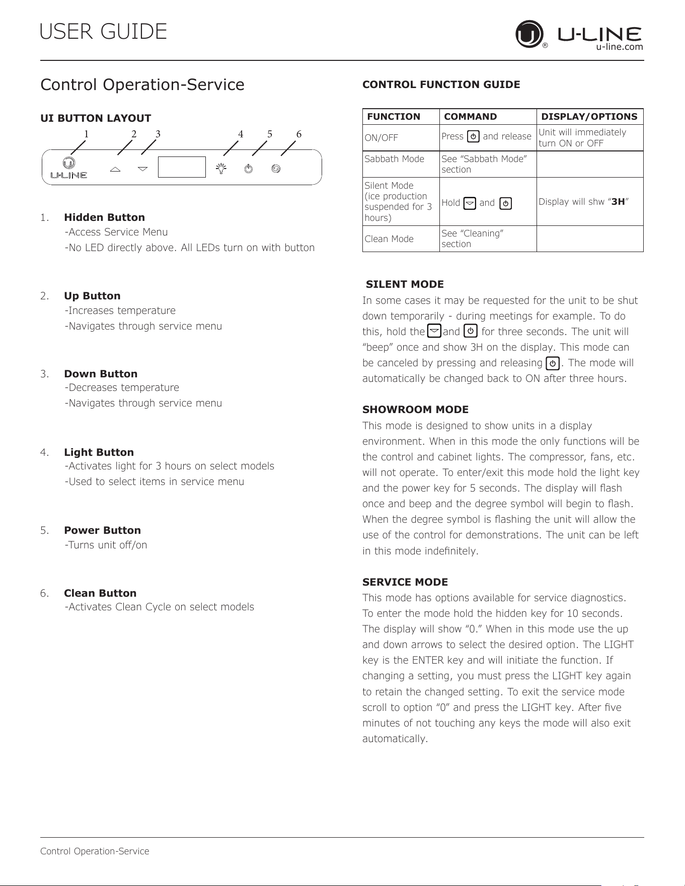
USER GUIDE
u-line.com
Control Operation-Service
Control Operation-Service
UI BUTTON LAYOUT
CONTROL FUNCTION GUIDE
FUNCTION COMMAND DISPLAY/OPTIONS
ON/OFF
Press
and release
Unit will immediately
turn ON or OFF
Sabbath Mode See “Sabbath Mode”
section
Silent Mode
(ice production
suspended for 3
hours)
Hold
and
Display will shw “3H”
Clean Mode
See “Cleaning”
section
1. Hidden Button
2. Up Button
3. Down Button
4. Light Button
5. Power Button
6. Clean Button
-Access Service Menu
-No LED directly above. All LEDs turn on with button
-Increases temperature
-Navigates through service menu
-Decreases temperature
-Navigates through service menu
-Activates light for 3 hours on select models
-Used to select items in service menu
-Turns unit o/on
-Activates Clean Cycle on select models
SILENT MODE
In some cases it may be requested for the unit to be shut
down temporarily - during meetings for example. To do
this, hold the and for three seconds. The unit will
“beep” once and show 3H on the display. This mode can
be canceled by pressing and releasing . The mode will
automatically be changed back to ON after three hours.
SHOWROOM MODE
This mode is designed to show units in a display
environment. When in this mode the only functions will be
the control and cabinet lights. The compressor, fans, etc.
will not operate. To enter/exit this mode hold the light key
and the power key for 5 seconds. The display will ash
once and beep and the degree symbol will begin to ash.
When the degree symbol is ashing the unit will allow the
use of the control for demonstrations. The unit can be left
in this mode indenitely.
SERVICE MODE
This mode has options available for service diagnostics.
To enter the mode hold the hidden key for 10 seconds.
The display will show “0.” When in this mode use the up
and down arrows to select the desired option. The LIGHT
key is the ENTER key and will initiate the function. If
changing a setting, you must press the LIGHT key again
to retain the changed setting. To exit the service mode
scroll to option “0” and press the LIGHT key. After ve
minutes of not touching any keys the mode will also exit
automatically.
1 2 3 4 5 6
51
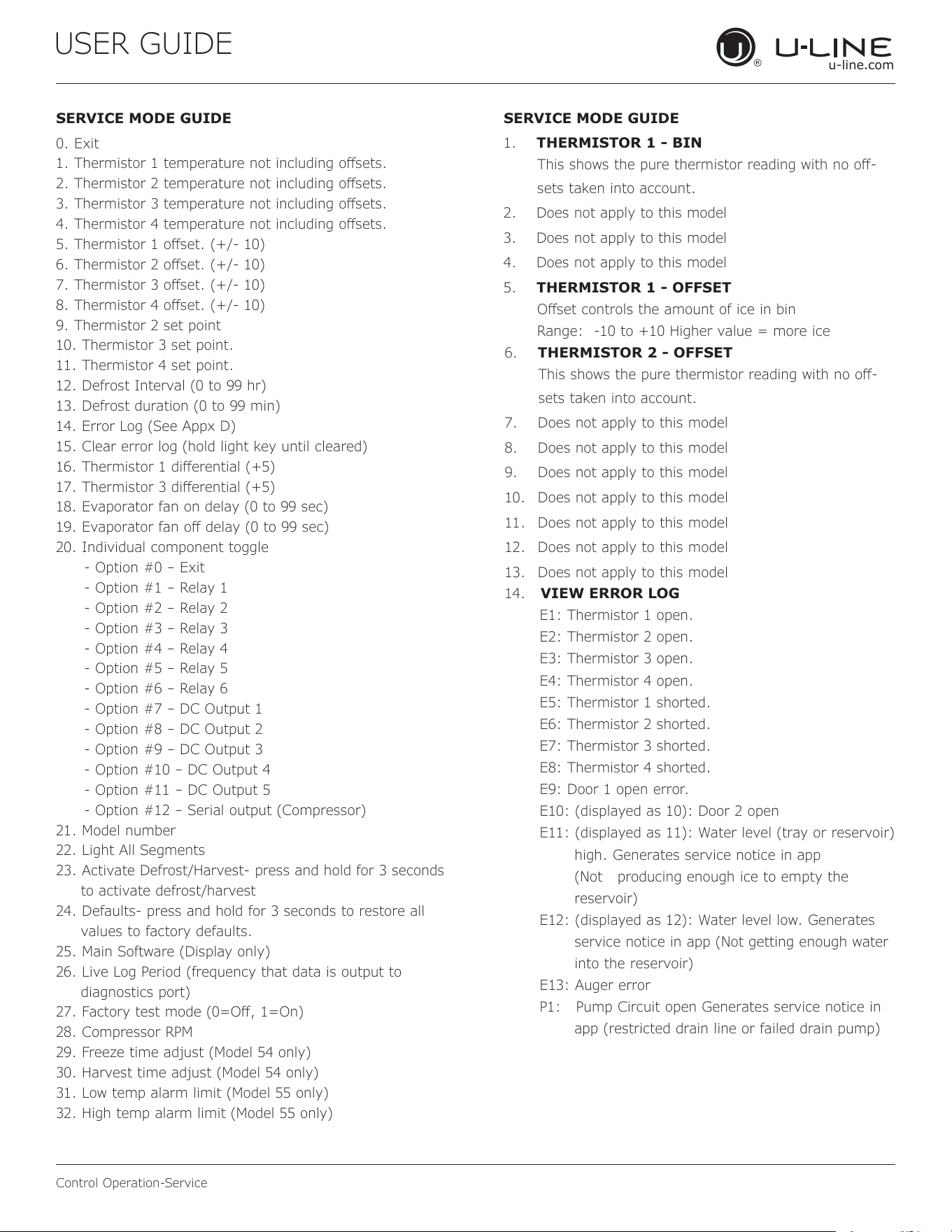
USER GUIDE
u-line.com
Control Operation-Service
SERVICE MODE GUIDE SERVICE MODE GUIDE
0. Exit
1. Thermistor 1 temperature not including osets.
2. Thermistor 2 temperature not including osets.
3. Thermistor 3 temperature not including osets.
4. Thermistor 4 temperature not including osets.
5. Thermistor 1 oset. (+/- 10)
6. Thermistor 2 oset. (+/- 10)
7. Thermistor 3 oset. (+/- 10)
8. Thermistor 4 oset. (+/- 10)
9. Thermistor 2 set point
10. Thermistor 3 set point.
11. Thermistor 4 set point.
12. Defrost Interval (0 to 99 hr)
13. Defrost duration (0 to 99 min)
14. Error Log (See Appx D)
15. Clear error log (hold light key until cleared)
16. Thermistor 1 dierential (+5)
17. Thermistor 3 dierential (+5)
18. Evaporator fan on delay (0 to 99 sec)
19. Evaporator fan o delay (0 to 99 sec)
20. Individual component toggle
- Option #0 – Exit
- Option #1 – Relay 1
- Option #2 – Relay 2
- Option #3 – Relay 3
- Option #4 – Relay 4
- Option #5 – Relay 5
- Option #6 – Relay 6
- Option #7 – DC Output 1
- Option #8 – DC Output 2
- Option #9 – DC Output 3
- Option #10 – DC Output 4
- Option #11 – DC Output 5
- Option #12 – Serial output (Compressor)
21. Model number
22. Light All Segments
23. Activate Defrost/Harvest- press and hold for 3 seconds
to activate defrost/harvest
24. Defaults- press and hold for 3 seconds to restore all
values to factory defaults.
25. Main Software (Display only)
26. Live Log Period (frequency that data is output to
diagnostics port)
27. Factory test mode (0=O, 1=On)
28. Compressor RPM
29. Freeze time adjust (Model 54 only)
30. Harvest time adjust (Model 54 only)
31. Low temp alarm limit (Model 55 only)
32. High temp alarm limit (Model 55 only)
1. THERMISTOR 1 - BIN
This shows the pure thermistor reading with no o-
sets taken into account.
2. Does not apply to this model
3. Does not apply to this model
4. Does not apply to this model
5. THERMISTOR 1 - OFFSET
Oset controls the amount of ice in bin
Range: -10 to +10 Higher value = more ice
6. THERMISTOR 2 - OFFSET
This shows the pure thermistor reading with no o-
sets taken into account.
7. Does not apply to this model
8. Does not apply to this model
9. Does not apply to this model
10.
Does not apply to this model
11.
Does not apply to this model
12.
Does not apply to this model
13.
Does not apply to this model
14. VIEW ERROR LOG
E1: Thermistor 1 open.
E2: Thermistor 2 open.
E3: Thermistor 3 open.
E4: Thermistor 4 open.
E5: Thermistor 1 shorted.
E6: Thermistor 2 shorted.
E7: Thermistor 3 shorted.
E8: Thermistor 4 shorted.
E9: Door 1 open error.
E10: (displayed as 10): Door 2 open
E11: (displayed as 11): Water level (tray or reservoir)
high. Generates service notice in app
(Not producing enough ice to empty the
reservoir)
E12: (displayed as 12): Water level low. Generates
service notice in app (Not getting enough water
into the reservoir)
E13: Auger error
P1: Pump Circuit open Generates service notice in
app (restricted drain line or failed drain pump)
52
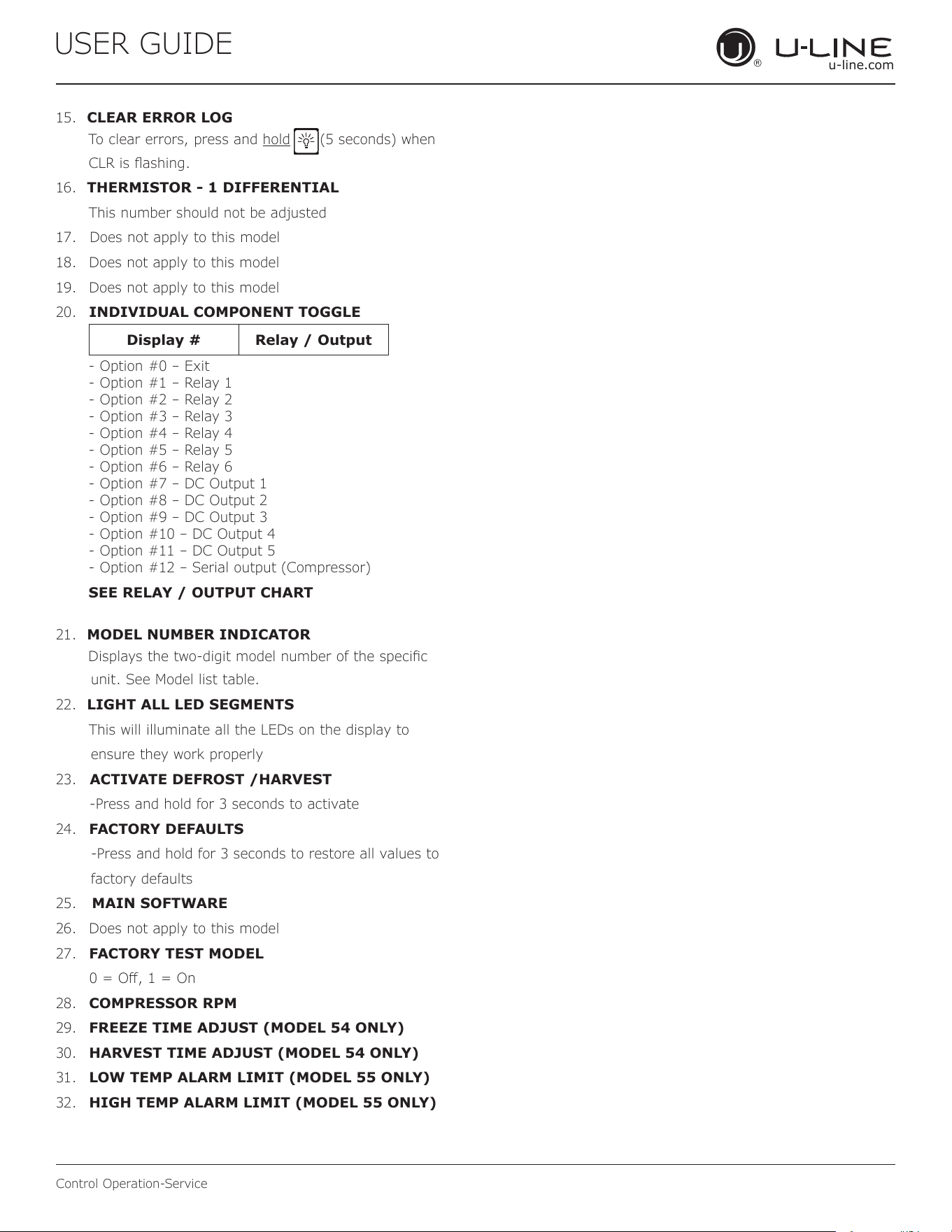
USER GUIDE
u-line.com
Control Operation-Service
15. CLEAR ERROR LOG
To clear errors, press and hold (5 seconds) when
CLR is ashing.
16. THERMISTOR - 1 DIFFERENTIAL
This number should not be adjusted
17. Does not apply to this model
18.
Does not apply to this model
19.
Does not apply to this model
20.
INDIVIDUAL COMPONENT TOGGLE
21. MODEL NUMBER INDICATOR
Displays the two-digit model number of the specic
unit. See Model list table.
22. LIGHT ALL LED SEGMENTS
This will illuminate all the LEDs on the display to
ensure they work properly
23. ACTIVATE DEFROST /HARVEST
-Press and hold for 3 seconds to activate
24.
FACTORY DEFAULTS
-Press and hold for 3 seconds to restore all values to
factory defaults
25. MAIN SOFTWARE
26.
Does not apply to this model
27.
FACTORY TEST MODEL
0 = O, 1 = On
28.
COMPRESSOR RPM
29.
FREEZE TIME ADJUST (MODEL 54 ONLY)
30.
HARVEST TIME ADJUST (MODEL 54 ONLY)
31.
LOW TEMP ALARM LIMIT (MODEL 55 ONLY)
32.
HIGH TEMP ALARM LIMIT (MODEL 55 ONLY)
Display # Relay / Output
- Option #0 – Exit
- Option #1 – Relay 1
- Option #2 – Relay 2
- Option #3 – Relay 3
- Option #4 – Relay 4
- Option #5 – Relay 5
- Option #6 – Relay 6
- Option #7 – DC Output 1
- Option #8 – DC Output 2
- Option #9 – DC Output 3
- Option #10 – DC Output 4
- Option #11 – DC Output 5
- Option #12 – Serial output (Compressor)
SEE RELAY / OUTPUT CHART
53
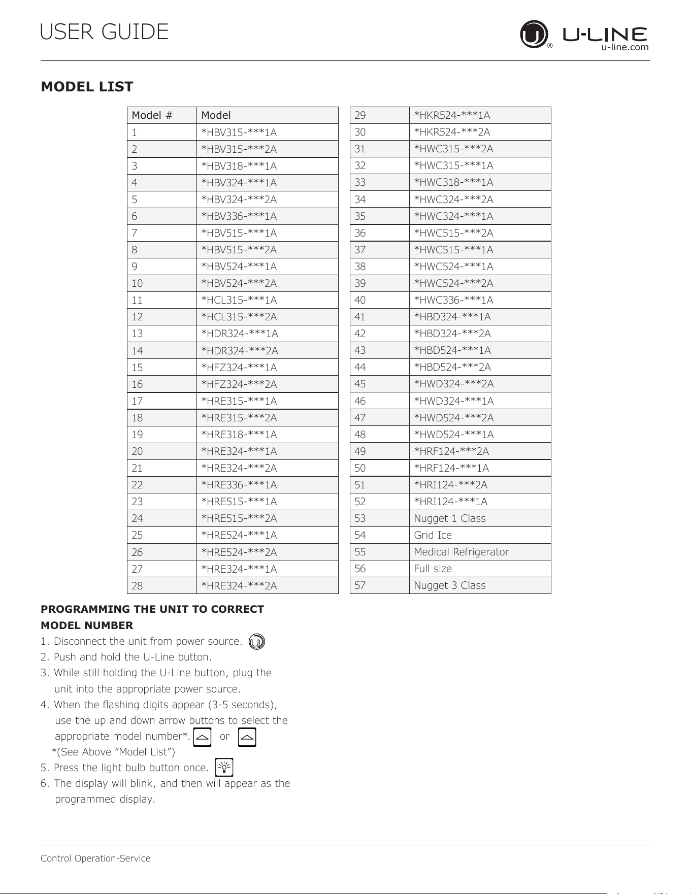
USER GUIDE
u-line.com
Control Operation-Service
MODEL LIST
Model # Model
1 *HBV315-***1A
2 *HBV315-***2A
3 *HBV318-***1A
4 *HBV324-***1A
5 *HBV324-***2A
6 *HBV336-***1A
7 *HBV515-***1A
8 *HBV515-***2A
9 *HBV524-***1A
10 *HBV524-***2A
11 *HCL315-***1A
12 *HCL315-***2A
13 *HDR324-***1A
14 *HDR324-***2A
15 *HFZ324-***1A
16 *HFZ324-***2A
17 *HRE315-***1A
18 *HRE315-***2A
19 *HRE318-***1A
20 *HRE324-***1A
21 *HRE324-***2A
22 *HRE336-***1A
23 *HRE515-***1A
24 *HRE515-***2A
25 *HRE524-***1A
26 *HRE524-***2A
27 *HRE324-***1A
28 *HRE324-***2A
29 *HKR524-***1A
30 *HKR524-***2A
31 *HWC315-***2A
32 *HWC315-***1A
33 *HWC318-***1A
34 *HWC324-***2A
35 *HWC324-***1A
36 *HWC515-***2A
37 *HWC515-***1A
38 *HWC524-***1A
39 *HWC524-***2A
40 *HWC336-***1A
41 *HBD324-***1A
42 *HBD324-***2A
43 *HBD524-***1A
44 *HBD524-***2A
45 *HWD324-***2A
46 *HWD324-***1A
47 *HWD524-***2A
48 *HWD524-***1A
49 *HRF124-***2A
50 *HRF124-***1A
51 *HRI124-***2A
52 *HRI124-***1A
53 Nugget 1 Class
54 Grid Ice
55 Medical Refrigerator
56 Full size
57 Nugget 3 Class
PROGRAMMING THE UNIT TO CORRECT
MODEL NUMBER
1. Disconnect the unit from power source.
2. Push and hold the U-Line button.
3. While still holding the U-Line button, plug the
unit into the appropriate power source.
4. When the ashing digits appear (3-5 seconds),
use the up and down arrow buttons to select the
appropriate model number*. or
*(See Above “Model List”)
5. Press the light bulb button once.
6. The display will blink, and then will appear as the
programmed display.
54
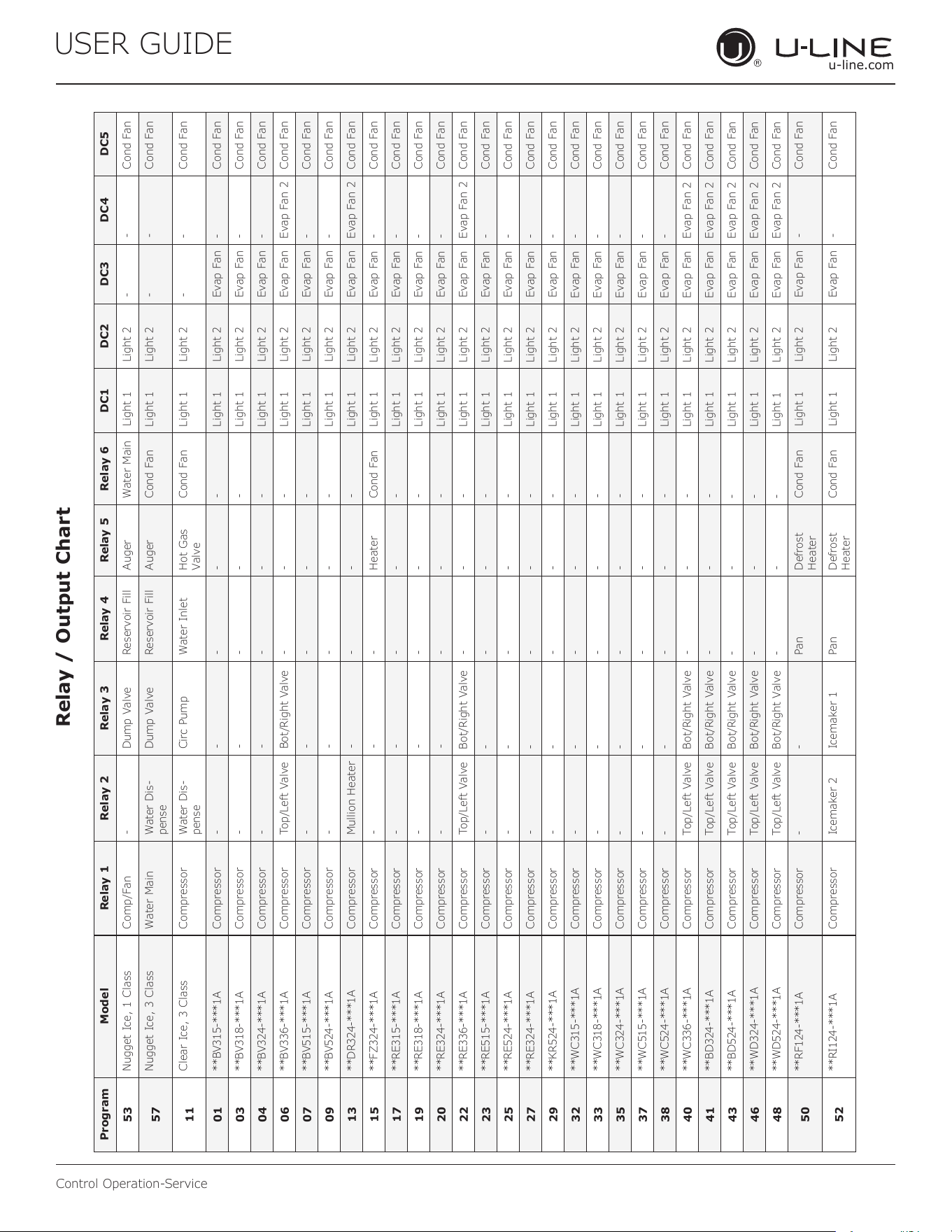
USER GUIDE
u-line.com
Control Operation-Service
Program Model Relay 1 Relay 2 Relay 3 Relay 4 Relay 5 Relay 6 DC1 DC2 DC3 DC4 DC5
53
Nugget Ice, 1 Class Comp/Fan - Dump Valve Reservoir Fill Auger Water Main Light 1 Light 2 - - Cond Fan
57
Nugget Ice, 3 Class Water Main Water Dis-
pense
Dump Valve Reservoir Fill Auger Cond Fan Light 1 Light 2 - - Cond Fan
11
Clear Ice, 3 Class Compressor Water Dis-
pense
Circ Pump Water Inlet Hot Gas
Valve
Cond Fan Light 1 Light 2 - - Cond Fan
01
**BV315-***1A Compressor - - - - - Light 1 Light 2 Evap Fan - Cond Fan
03
**BV318-***1A Compressor - - - - - Light 1 Light 2 Evap Fan - Cond Fan
04
**BV324-***1A Compressor - - - - - Light 1 Light 2 Evap Fan - Cond Fan
06
**BV336-***1A Compressor Top/Left Valve Bot/Right Valve - - - Light 1 Light 2 Evap Fan Evap Fan 2 Cond Fan
07
**BV515-***1A Compressor - - - - - Light 1 Light 2 Evap Fan - Cond Fan
09
**BV524-***1A Compressor - - - - - Light 1 Light 2 Evap Fan - Cond Fan
13
**DR324-***1A Compressor Mullion Heater - - - - Light 1 Light 2 Evap Fan Evap Fan 2 Cond Fan
15
**FZ324-***1A Compressor - - - Heater Cond Fan Light 1 Light 2 Evap Fan - Cond Fan
17
**RE315-***1A Compressor - - - - - Light 1 Light 2 Evap Fan - Cond Fan
19
**RE318-***1A Compressor - - - - - Light 1 Light 2 Evap Fan - Cond Fan
20
**RE324-***1A Compressor - - - - - Light 1 Light 2 Evap Fan - Cond Fan
22
**RE336-***1A Compressor Top/Left Valve Bot/Right Valve - - - Light 1 Light 2 Evap Fan Evap Fan 2 Cond Fan
23
**RE515-***1A Compressor - - - - - Light 1 Light 2 Evap Fan - Cond Fan
25
**RE524-***1A Compressor - - - - - Light 1 Light 2 Evap Fan - Cond Fan
27
**RE324-***1A Compressor - - - - - Light 1 Light 2 Evap Fan - Cond Fan
29
**KR524-***1A Compressor - - - - - Light 1 Light 2 Evap Fan - Cond Fan
32
**WC315-***1A Compressor - - - - - Light 1 Light 2 Evap Fan - Cond Fan
33
**WC318-***1A Compressor - - - - - Light 1 Light 2 Evap Fan - Cond Fan
35
**WC324-***1A Compressor - - - - - Light 1 Light 2 Evap Fan - Cond Fan
37
**WC515-***1A Compressor - - - - - Light 1 Light 2 Evap Fan - Cond Fan
38
**WC524-***1A Compressor - - - - - Light 1 Light 2 Evap Fan - Cond Fan
40
**WC336-***1A Compressor Top/Left Valve Bot/Right Valve - - - Light 1 Light 2 Evap Fan Evap Fan 2 Cond Fan
41
**BD324-***1A Compressor Top/Left Valve Bot/Right Valve - - - Light 1 Light 2 Evap Fan Evap Fan 2 Cond Fan
43
**BD524-***1A Compressor Top/Left Valve Bot/Right Valve - - - Light 1 Light 2 Evap Fan Evap Fan 2 Cond Fan
46
**WD324-***1A Compressor Top/Left Valve Bot/Right Valve - - - Light 1 Light 2 Evap Fan Evap Fan 2 Cond Fan
48
**WD524-***1A Compressor Top/Left Valve Bot/Right Valve - - - Light 1 Light 2 Evap Fan Evap Fan 2 Cond Fan
50
**RF124-***1A Compressor - -
Pan Defrost
Heater
Cond Fan Light 1 Light 2 Evap Fan - Cond Fan
52
**RI124-***1A Compressor Icemaker 2 Icemaker 1 Pan Defrost
Heater
Cond Fan Light 1 Light 2 Evap Fan - Cond Fan
Relay / Output Chart
55
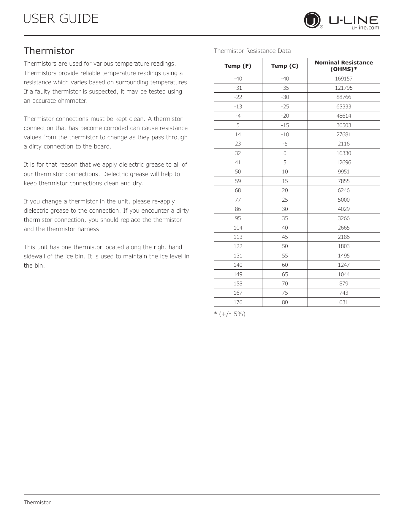
USER GUIDE
u-line.com
Thermistor
Thermistors are used for various temperature readings.
Thermistors provide reliable temperature readings using a
resistance which varies based on surrounding temperatures.
If a faulty thermistor is suspected, it may be tested using
an accurate ohmmeter.
Thermistor connections must be kept clean. A thermistor
connection that has become corroded can cause resistance
values from the thermistor to change as they pass through
a dirty connection to the board.
It is for that reason that we apply dielectric grease to all of
our thermistor connections. Dielectric grease will help to
keep thermistor connections clean and dry.
If you change a thermistor in the unit, please re-apply
dielectric grease to the connection. If you encounter a dirty
thermistor connection, you should replace the thermistor
and the thermistor harness.
This unit has one thermistor located along the right hand
sidewall of the ice bin. It is used to maintain the ice level in
the bin.
Thermistor Resistance Data
* (+/- 5%)
Thermistor
Temp (F) Temp (C)
Nominal Resistance
(OHMS)*
-40 -40 169157
-31 -35 121795
-22 -30 88766
-13 -25 65333
-4 -20 48614
5 -15 36503
14 -10 27681
23 -5 2116
32 0 16330
41 5 12696
50 10 9951
59 15 7855
68 20 6246
77 25 5000
86 30 4029
95 35 3266
104 40 2665
113 45 2186
122 50 1803
131 55 1495
140 60 1247
149 65 1044
158 70 879
167 75 743
176 80 631
56
Copyright © 2020 U-Line Corporation. All Rights Reserved. | Publication Number 30379 | 11/2020 Rev. O
U-Line Corporation (U-Line) Limited Warranty
One Year Limited Warranty
For one year from the date of original purchase, this warranty covers all parts and labor to repair or replace any part of the product that
proves to be defective in materials or workmanship. For products installed and used for normal residential use, material cosmetic defects
are included in this warranty, with coverage limited to 60 days from the date of original purchase. All service provided by U-Line under the
above warranty must be performed by a U-Line factory authorized servicer, unless otherwise specified by U-Line. Service provided during
normal business hours.
Two Year Limited Warranty (5 Class Product)
For two years from the date of original purchase, this warranty covers all parts and labor to repair or replace any part of the product that
proves to be defective in materials or workmanship. For products installed and used for normal residential use, material cosmetic defects
are included in this warranty, with coverage limited to 60 days from the date of original purchase. All service provided by U-Line under the
above warranty must be performed by a U-Line factory authorized servicer, unless otherwise specified by U-Line. Service provided during
normal business hours.
Available Second & Third Year Limited Warranty
In addition to the standard one and two year warranties outlined above, U-Line offers a one year extension of the warranties from the date
of purchase, free of charge. To take advantage of this extension, you must register your product with U-Line within 60 days from the date
of purchase at u-line.com and provide proof of purchase.
Five Year Sealed System Limited Warranty
For five years from the date of original purchase, U-Line will repair or replace the following parts, labor not included, that prove to be
defective in materials or workmanship: compressor, condenser, evaporator, drier, and all connecting tubing. All service provided by U-Line
under the above warranty must be performed by a U-Line factory authorized servicer, unless otherwise specified by U-Line. Service
provided during normal business hours.
Terms
These warranties apply only to products installed in any one of the fifty states of the United States, the District of Columbia, or the ten
provinces of Canada. The warranties do not cover any parts or labor to correct any defect caused by negligence, accident or improper use,
maintenance, installation, service, repair, acts of God, fire, flood or other natural disasters. The product must be installed, operated, and
maintained in accordance with your product’s User Guide.
The remedies described above for each warranty are the only ones that U-Line will provide, either under these warranties or under any
warranty arising by operation of law. U-Line will not be responsible for any consequential or incidental damages arising from the breach of
these warranties or any other warranty, whether express, implied, or statutory. Some states do not allow the exclusion or limitation of
incidental or consequential damages, so the above limitation or exclusion may not apply to you. These warranties give you specific legal
rights, and you may also have other rights which vary from state to state.
Any warranty that may be implied in connection with your purchase or use of the product, including any warranty of merchantability or any
warranty fit for a particular purpose is limited to the duration of these warranties, and only extends to five years in duration for the parts
described in the section related to the five year limited warranty above. Some states do not allow limitations on how long an implied warranty
lasts, so the above limitations may not apply to you.
• The warranties only apply to the original purchaser and are non-transferable.
• The second, third, and five year warranties cover products installed and used for normal residential or designated marine use only.
• The warranties apply to units operated outside only if designed for outdoor use by model and serial number.
• U-Line Commercial products are covered by the one year and 5 year limited warranties and are not eligible for the second and
third year limited warranties.
• Replacement water filters, light bulbs, and other consumable parts are not covered by these warranties.
• The start of U-Line’s obligation is limited to four years after the shipment date from U-Line.
• In-home instruction on how to use your product is not covered by these warranties.
• Food, beverage, and medicine loss are not covered by these warranties.
• If the product is located in an area where U-Line factory authorized service is not available, you may be responsible for a trip
charge or you may be required to bring the product to a U-Line factory authorized service location at your own cost and expense.
• Units purchased after use as floor displays, and/or certified reconditioned units, are covered by the limited one year warranty only
and no coverage is provided for cosmetic defects.
• Signal issues related to Wi-Fi connectivity are not covered by these warranties.
For parts and service assistance, or to find U-Line factory authorized service near you, contact U-Line:
8900 N. 55
th
Street, Milwaukee, WI 53223 • u-line.com • onlineservice@u-line.com •
+1.414.354.0300
57