USER GUIDE & SERVICE MANUAL
Model: URNP115-IS01A

USER GUIDE
u-line.com
Introduction
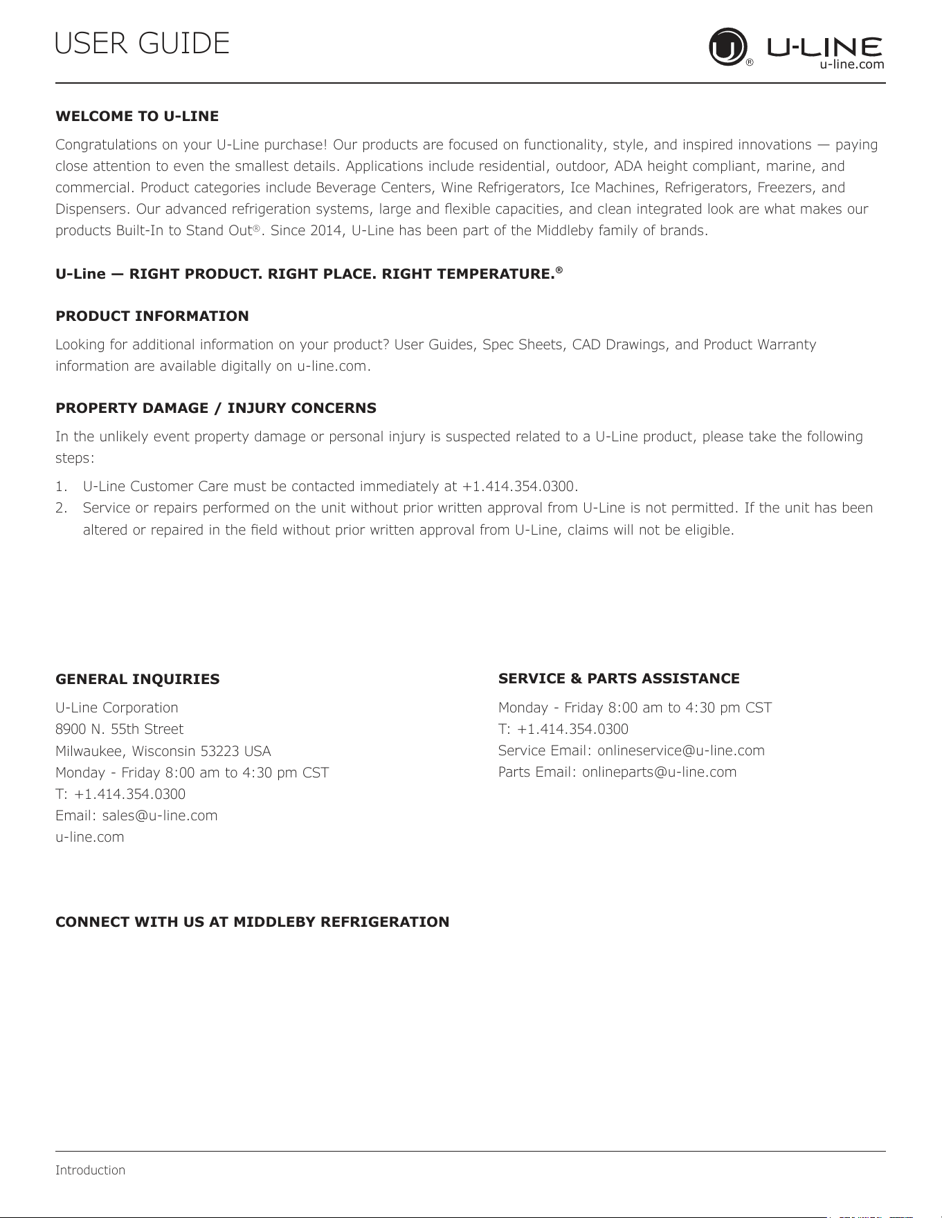
WELCOME TO U-LINE
Congratulations on your U-Line purchase! Our products are focused on functionality, style, and inspired innovations — paying
close attention to even the smallest details. Applications include residential, outdoor, ADA height compliant, marine, and
commercial. Product categories include Beverage Centers, Wine Refrigerators, Ice Machines, Refrigerators, Freezers, and
Dispensers. Our advanced refrigeration systems, large and exible capacities, and clean integrated look are what makes our
products Built-In to Stand Out
®
. Since 2014, U-Line has been part of the Middleby family of brands.
U-Line — RIGHT PRODUCT. RIGHT PLACE. RIGHT TEMPERATURE.
®
PRODUCT INFORMATION
Looking for additional information on your product? User Guides, Spec Sheets, CAD Drawings, and Product Warranty
information are available digitally on u-line.com.
PROPERTY DAMAGE / INJURY CONCERNS
In the unlikely event property damage or personal injury is suspected related to a U-Line product, please take the following
steps:
1. U-Line Customer Care must be contacted immediately at +1.414.354.0300.
2. Service or repairs performed on the unit without prior written approval from U-Line is not permitted. If the unit has been
altered or repaired in the eld without prior written approval from U-Line, claims will not be eligible.
GENERAL INQUIRIES
U-Line Corporation
8900 N. 55th Street
Milwaukee, Wisconsin 53223 USA
Monday - Friday 8:00 am to 4:30 pm CST
T: +1.414.354.0300
Email: sales@u-line.com
u-line.com
CONNECT WITH US AT MIDDLEBY REFRIGERATION
SERVICE & PARTS ASSISTANCE
Monday - Friday 8:00 am to 4:30 pm CST
T: +1.414.354.0300
Service Email: onlineservice@u-line.com
Parts Email: onlineparts@u-line.com
3

USER GUIDE
Integrated Panel Dimensions
Integrated Panel Dimensions
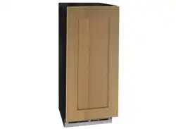
INTEGRATED PANEL
Due to dierences in surrounding cabinetry, the
panel may not perfectly align with door. The pro-
cedure below is designed to prepare a nished
integrated panel that seamlessly integrates with
surrounding cabinetry.
The door panel must not weigh more than 20 lbs
(10 kg).
It is important to ensure that all drilled holes
are drilled to the correct depth in order to avoid
splits in the wood when hardware is installed.
When applying an integrated panel to a unit
ensure that both sides are nished in order to
prevent warping.
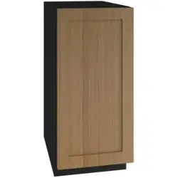
A full integrated door panel completely covers the door
frame and provides a built-in appearance.
Integrated Panel Preparation
1. Cut the panels to the dimensions listed in the diagram
below. For optimal results, have a qualied carpenter
verify all measurements.
2. Optional: Stain or Finish panel to desired stain or col-
or. Be sure to closely follow the instructions provided
by the manufacturer.
3. Optional: Install handles and hardware.
Integrated Panel Dimensions
NOTICE
BACK SURFACE MUST HAVE AMPLE FLAT SURFACE
TO MOUNT OVERLAY PANEL FLAT AND WITHOUT
INTERFERENCE
30”
(762 mm)
14 15⁄16”
(379 mm)
3/4”
(19 mm)
4
USER GUIDE
Integrated Panel Installation
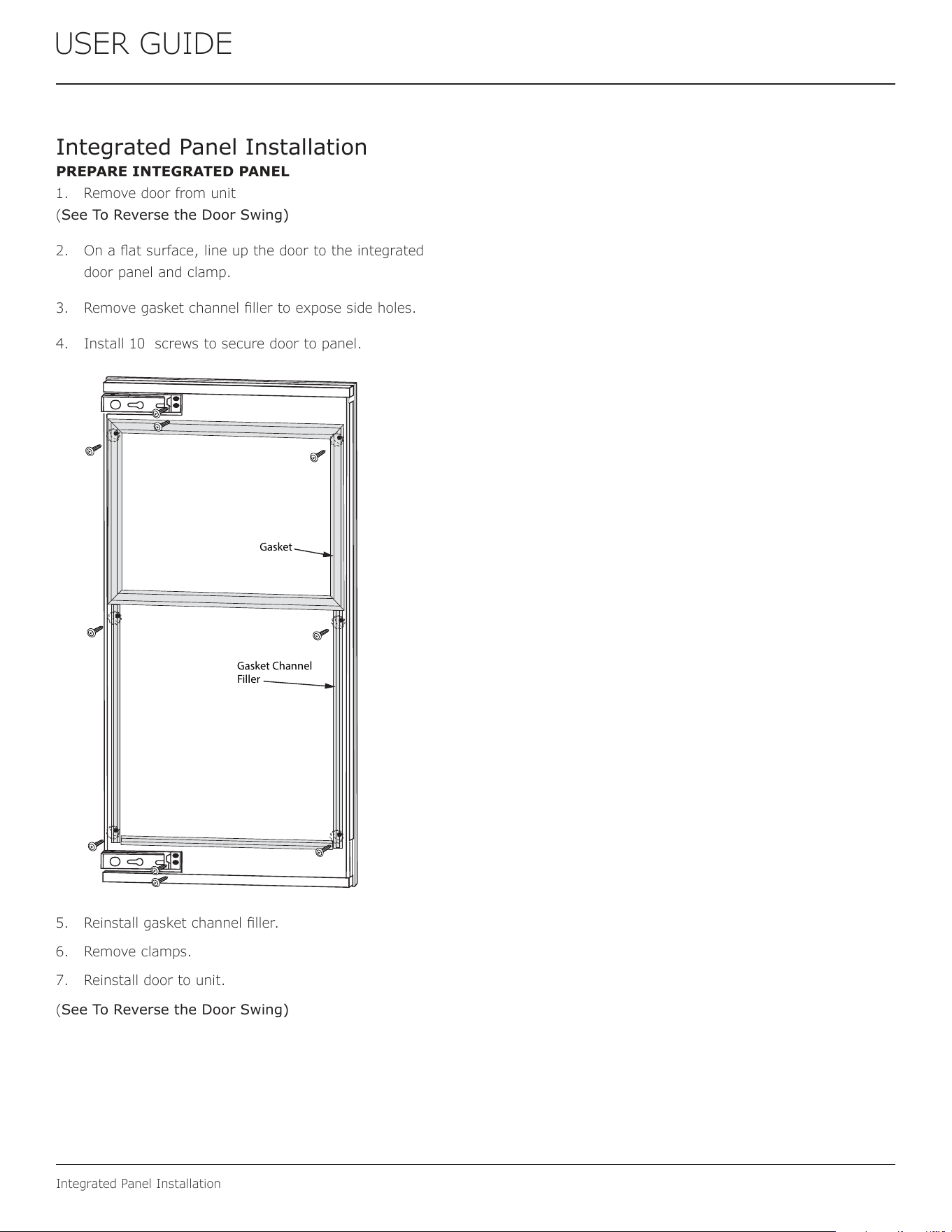
Integrated Panel Installation
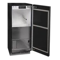
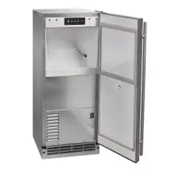
PREPARE INTEGRATED PANEL
1. Remove door from unit
(See To Reverse the Door Swing)
2. On a at surface, line up the door to the integrated
door panel and clamp.
3. Remove gasket channel ller to expose side holes.
4. Install 10 screws to secure door to panel.
5. Reinstall gasket channel ller.
6. Remove clamps.
7. Reinstall door to unit.
(See To Reverse the Door Swing)
Gasket
Gasket Channel
Filler
5