Loading ...
Loading ...
Loading ...
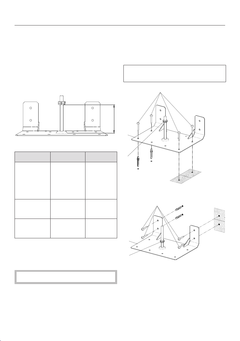
Anti-tip device
*INSTALLATION*
99
Included accessories
- 1 anti-tip device
- 4 screws
- 4 plugs
Installation dimensions of
locking bolt
X
Anti-tip device, front view
Model Width X
HR1124-3
HR1421-3*
HR1622-3
HR1724-3
HR1924-3
2915/16"
(762mm)
313/16"
(97mm)
HR113x-3
HR193x-3
3515/16"
(915mm)
313/16"
(97mm)
HR195x-3 4715/16"
(1,220mm)
31/4"
(82mm)
* Only available in Canada.
Installing the Range with the
anti-tip device
Wear safety shoes and gloves.
The anti-tip device should be installed
at the bottom rear of the Range at the
midpoint of the width.
Measure the installation space for the
Range close to floor level.
Mark the wall at the middle of the
space width.
Position the notch of the anti-tip
device on the wall marking.
The anti-tip device must fit tightly on
the floor or the wall.
1
3
2
Attaching to the floor
1
2
3
Attaching to the wall
a
Anti-tip device
b
Screws
c
Locking nut
Loading ...
Loading ...
Loading ...