Loading ...
Loading ...
Loading ...
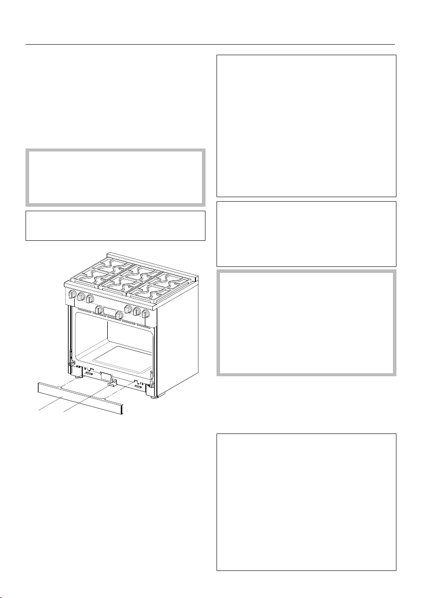
Anti-tip device
*INSTALLATION*
100
Using four screws , secure the anti-
tip device to the floor surface with
suitable bearing capacity, either to
the floor or wall.
Screw the locking nut to the bolt;
see the “Installation dimensions of
locking bolt” table.
Do not push the Range into
position before all supply
connections have been
established.
The toe kick panel is attached to the
toe kick of the Range by magnets.
21
a
Toe kick panel
b
Locking clamp
Remove the toe kick panel from
the Range.
Pull out the locking clamp .
The locking clamp extends through
the toe kick panel of the Range
housing. It can be pulled out and
pushed back in again. Its length is
approximately equal to the depth of
the Range.
A slot is located in the non-visible rear
section of the locking latch. This slot
engages with the bolt of the anti-tip
device when you slide the locking
latch into the Range.
Complete all necessary connections
for the Range. Read the information in
the “Electrical connection”, “Gas
connection”, and “Plumbed water
connection” sections.
The Range can be damaged if it is
lifted using the panel, the island trim,
or the door handle.
Open the oven door and hold the
appliance by the front of the oven
cavity.
Lift the Range and move it with the
help of the rear wheels.
Slide the Range into position, guiding
the middle of the appliance onto the
anti-tip device. Slide the appliance all
the way back to the wall.
The Range can be aligned if
necessary. Check it with a level.
- Rear adjustment right and left:
You will need an open-end wrench
(3/8" (10mm)).
-
Front adjustment right and left:
You will need an open-end wrench
(5/8" (16mm)) for the locknut and
an open-end wrench (1/2" (13mm))
for the adjustable nut.
Loading ...
Loading ...
Loading ...