Operator's Manual
CRRFr MRN
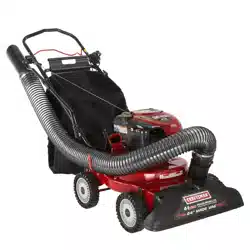
POWER PROPELLED YARD VACUUM
Model No. 247.770131
CAUTION" Before using this
product, read this manual and
follow all safety rules and operating
instructions.
,, SAFETY
o ASSEMBLY
OPERATION
MAINTENANCE
PARTS LIST
o ESPANOL
Sears Brands Management Corporation, Hoffman Estates, IL 60179, U.S.A.
Visit our website: www.craftsman.com FormNo. 769-05107C
(June 12,2012)
Warranty Statement .................................. Page 2
Safe Operation Practices .......................... Page 3
Safety Labels ............................................ Page 7
Assembly .................................................. Page 8
Operation .................................................. Page 12
Service and Maintenance ......................... Page 16
Off-Season Storage .................................. Page 22
Trouble Shooting ....................................... Page 23
Parts List ................................................... Page 24
Repair Protection Agreement ................... Page 38
Espa_ol ..................................................... Page 39
Service Numbers ...................................... Back Cover
CRAFTSMAN TWO YEAR FULL WARRANTY
FORTWOYEAR(S)fromthe dateof purchase,thisproductiswarrantedagainstanydefectsinmaterialor workmanship.A defectiveproductwill
receivefree repairor replacementif repairis unavailable.
Forwarrantycoveragedetailsto obtainfree repairor replacement,visitthe web site:www.craftsman.com
ThiswarrantycoversONLYdefectsin materialand workmanship.Warrantycoveragedoes NOTinclude:
• Expendableitemsthatcan wearout from normaluse withinthe warrantyperiod,suchas the blades, sparkplug,aircleaner,flail
screenand catcherbag.
• Productdamageresultingfromuserattemptsat productmodificationor repairor causedby productaccessories.
• Repairsnecessarybecauseof accidentor failureto operateor maintainthe productaccordingto all suppliedinstructions.
• Preventivemaintenance,or repairsnecessarydue to improperfuel mixture,contaminatedor stalefuel.
Thiswarrantyis voidif this productis everusedwhileprovidingcommercialservicesor if rentedto anotherperson.
Thiswarrantygives youspecificlegal rights,andyoumay also haveother rightswhichvary from stateto state.
Sears Brands Management Corporation, Hoffman Estates, IL 60179
EngineSeries: 675
EngineOilType: SAE30
EngineOilCapacity: 18ounces
FuelCapacity: 1.5Quarts
SparkPlug Gap: .020"
Model Number.................................................................
Serial Number.................................................................
Dateof Purchase .............................................................
Recordthe modelnumber,serialnumber
anddateof purchaseabove
© Sears Brands,LLC 2
Thissymbolpointsout importantsafetyinstructionswhich,if not
followed,couldendangerthe personalsafetyand/orpropertyof
yourselfandothers. Readandfollowall instructionsin this manual
beforeattemptingto operatethismachine.Failureto complywith
theseinstructionsmayresultin personalinjury.Whenyou seethis
symbol,HEEDITSWARNING!
CALIFORNIA PROPOSITION 65
EngineExhaust,someof itsconstituents,and certainvehicle
componentscontainoremit chemicalsknownto Stateof California
to causecancerandbirthdefectsor other reproductiveharm.
Thismachinewas built to be operatedaccordingto the safe opera-
tion practicesin thismanual.As with any type of powerequipment,
carelessnessor erroronthe part of the operatorcan resultin
seriousinjury.Thismachineis capableof amputatingfingers,hands,
toesandfeet andthrowingdebris. Failureto observethe following
safetyinstructionscouldresultin seriousinjuryordeath.
Your Responsibility--Restrictthe use of this powermachineto
personswho read,understandand followthewarningsand instruc-
tionsin thismanualandon the machine.
SAVETHESEINSTRUCTIONS!
TRAINING
• Read,understand,and followall instructionson the machineand
in themanualbeforeattemptingto assembleandoperate.Keep
thismanualina safeplacefor futureandregularreferenceand for
orderingreplacementparts.
• Readthe Operator'sManualand followall warningsand safety
instructions.Failureto do so can resultin seriousinjuryto the
operatorand/orbystanders.Forquestionscall, 1-800-4MY-
HOME.
• Befamiliarwith all controlsandtheir properoperation.Knowhow
to stopthe machineand disengagethemquickly.
• Neverallowchildrenunder16 yearsof age to operatethis
machine.Children16 andovershouldreadand understandthe
instructionsand safeoperationpracticesin this manualandon
the machineandbe trainedand supervisedby an adult.
• Neverallowadultsto operatethis machinewithoutproper
instruction.
• Keepbystanders,pets,andchildrenat least75 feetfromthe
machinewhile it is in operation.Stopmachineif anyoneenters
the area.
• Neverrunan engineindoorsor in a poorlyventilatedarea.Engine
exhaustcontainscarbonmonoxide,an odorlessanddeadlygas.
• Do not puthandsand feetnearrotatingpartsor in the feeding
chambersanddischargeopening.Contactwiththe rotating
impellercan amputatefingers,hands,and feet.
• Neverattemptto unclogeitherthe feed intakeordischarge
opening,removeor emptybag,or inspectand repairthe machine
whilethe engineis running.Shutthe engineoff and waituntilall
movingpartshavecome to a completestop.Disconnectthe spark
plugwireandgroundit againstthe engine.
PREPARATION
• Thoroughlyinspectthearea wherethe equipmentis to be used.
Removeall rocks,bottles,cans,or otherforeignobjectswhich
could bepickedupor thrownand causepersonalinjuryor
damageto the machine.
• Alwayswear safetyglassesor safetygogglesduringoperation
andwhile performingan adjustmentor repair,to protectyour
eyes.Thrownobjectswhichricochetcan cause seriousinjuryto
the eyes.
• Wearsturdy,rough-soledworkshoesand close-fittingslacksand
shirts.Loosefittingclothesor jewelrycan be caughtin movable
parts.Neveroperatethismachinein barefeetor sandals.Wear
leatherworkgloveswhenfeedingmaterialin the chipperchute.
• Beforestarting,checkallboltsand screwsfor propertightnessto
besurethe machineis insafeworkingcondition.Also,visually
inspectmachinefor any damageat frequentintervals.
• Maintainor replacesafetyand instructionslabels,as necessary.
3
Safe Handling of Gasoline:
Toavoidpersonalinjuryor propertydamageuseextremecare in
handlinggasoline.Gasolineis extremelyflammableandthe vaporsare
explosive.Seriouspersonalinjurycan occurwhengasolineis spilled
onyourselfor yourclotheswhichcan ignite.Washyour skinand
changeclothesimmediately.
• Useonlyan approvedgasolinecontainer.
• Neverfill containersinsidea vehicleor on a truckor trailerbed
witha plasticliner.Alwaysplacecontainerson the groundaway
fromyour vehiclebeforefilling.
• Whenpractical,removegas-poweredequipmentfromthe truck
ortrailerand refuelitonthe ground.Ifthisis notpossible,then
refuelsuchequipmenton a trailerwith a portablecontainer,rather
thanfrom a gasolinedispensernozzle.
• Keepthe nozzleincontactwith the rimof the fuel tankor
containeropeningat alltimes untilfuelingis complete.Do not use
a nozzlelock-opendevice.
• Extinguishall cigarettes,cigars,pipesandother sourcesof
ignition.
• Neverfuel machineindoors.
• Neverremovegas capor add fuel whilethe engineishot or run-
ning.Allowengineto cool at leasttwo minutesbeforerefueling.
• Neveroverfill fueltank. Fill tankto nomorethan1/2inchbelow
bottomof filler neck to allowspacefor fuel expansion.
• Replacegasolinecapand tightensecurely.
• Ifgasolineisspilled,wipe itoff theengineandequipment.Move
unitto anotherarea.Wait5 minutesbeforestartingthe engine.
• To reducefire hazards,keepmachinefreeof grass, leaves,or
otherdebrisbuild-up.Cleanupoil or fuel spillageand removeany
fuel soakeddebris.
• Neverstorethe machineorfuel containerinsidewherethereis an
openflame,spark or pilotlightas on awater heater,spaceheater,
furnace,clothesdryer or othergas appliances.
OPERATION
• Do not puthandsand feetnearrotatingpartsor in thefeeding
chambersand dischargeopening.Contactwiththe rotating
impellercan amputatefingers,hands,and feet.
• Beforestartingthe machine,makesurethe chipperchute,feed
intake,andcuttingchamberare emptyandfreeof all debris.
• Thoroughlyinspectall materialto be shreddedand removeany
metal,rocks,bottles,cans,or otherforeignobjectswhichcould
causepersonalinjuryor damageto the machine.
• Ifthe impellerstrikesa foreignobjector if yourmachineshould
start makinganunusualnoiseor vibration,immediatelyshut
the engineoff. Allowthe impellerto come toa completestop.
Disconnectthe sparkplug wire,grounditagainstthe engineand
performthe followingsteps:
a. Inspectfor damage.
b. Repairor replaceanydamagedparts.
c. Checkfor anyloose partsandtightento assurecontinued
safeoperation.
• Donot allowanaccumulationof processedmaterialto build upin
the dischargearea.Thiscan preventproperdischargeandresult
inkickbackof materialthroughthe feedopening.
• Donot attemptto shredorchip materiallargerthanspecified
on the machineor inthis manual.Personalinjuryor machine
damagecould result.
• Neverattemptto unclogeitherthe feedintakeor discharge
openingwhilethe engineis running.Shuttheengineoff,waituntil
all movingpartshavestopped,disconnectthe spark plug wireand
grounditagainsttheengine beforeclearingdebris.
• Neveroperatewithoutvacuumbag and dischargechuteproperly
attachedtothe machine.Neveremptyor changevacuumbag
whilethe engine isrunning.Vacuumbagmustbe keptclosedat
all timesduringoperation.
• Neveroperatewithouteitherthe inletnozzleor optionalhose
attachment(if applicable)properlyattachedto the machine.
Neverattemptto attachor changeeitherattachmentwhile the
engineis running.
• Keepallguards,deflectorsand safetydevicesin placeand
operatingproperly.
• Keepyourface andbodybackandto the sideof the chipper
chutewhilefeedingmaterialintothe machineto avoidaccidental
kickbackinjuries.
• Neveroperatethis machinewithoutgoodvisibilityor light.Always
be sureof yourfootingand keepa firm holdon the handles.
• Donot operatethismachineona paved,gravelor non-level
surface.
• Donot operatethismachinewhileunderthe influenceof alcohol
or drugs.
• Mufflerandenginebecomehot and cancause a burn.Do not
touch.
• Neverpick upor carrymachinewhilethe engineis running.
• Ifsituationsoccur whichare notcoveredinthis manual,use care
andgoodjudgement.ContactCustomerSupportforassistance
andthe nameof the nearestservicedealer.
4
MAINTENANCE & STORAGE
• Nevertamperwithsafetydevices.Checktheirproperoperation
regularly.
• Checkboltsand screwsfor propertightnessat frequentintervals
to keepthe machinein safeworkingcondition.Also,visually
inspectmachinefor anydamageand repair,if needed.
Beforecleaning,repairing,or inspecting,stopthe engineand
makecertainthe impellerand allmovingparts havestopped.
Disconnectthe spark plugwire and groundit againstthe engine
to preventunintendedstarting.
Do notchangetheenginegovernorsettingsor overspeedthe
engine.Thegovernorcontrolsthe maximumsafeoperatingspeed
of the engine.
Maintainor replacesafetyandinstructionlabels,as necessary.
Followthismanualfor safe loading,unloading,transporting,and
storageof thismachine.
Neverstorethe machineorfuel containerinsidewherethereis an
openflame,spark orpilot lightsuchas a waterheater,furnace,
clothesdryer,etc.
Allowmachineto cool at least 5 minutesbeforestoring.
• Alwaysreferto the operator'smanualfor properinstructionson
off-seasonstorage.
• If thefuel tank hasto be drained,do thisoutdoors.
• Observeproperdisposallawsand regulationsfor gas,oil,etc. to
protectthe environment.
• Accordingto the ConsumerProductsSafetyCommission(CPSC)
andthe U.S.EnvironmentalProtectionAgency(EPA),this product
hasan Average UsefulLifeof seven(7) years,or 60 hoursof
operation.At the endof theAverageUsefulLifehavethe machine
inspectedannuallybyan authorizedservicedealer to ensurethat
allmechanicaland safetysystemsareworkingproperlyand not
wornexcessively.Failureto do so can resultinaccidents,injuries
ordeath.
DO NOT MODIFY ENGINE
Toavoidseriousinjuryordeath,do not modifyenginein anyway.
Tamperingwiththe governorsettingcan leadto a runawayengineand
causeit to operateat unsafespeeds.Nevertamperwithfactory setting
of enginegovernor.
NOTICE REGARDING EMISSIONS
Engineswhich arecertifiedtocomplywithCaliforniaand federal
EPAemissionregulationsfor SORE(SmallOff RoadEquipment)are
certifiedto operateon regularunleadedgasoline,and mayinclude
the followingemissioncontrol systems:EngineModification(EM),
OxidizingCatalyst(OC), SecondaryAirInjection(SAI)and ThreeWay
Catalyst(TWO)if so equipped.
SPARK ARRESTOR
Thismachineis equippedwith an internalcombustionengineand
shouldnotbe usedonor nearanyunimprovedforest-covered,
brushcoveredor grass-coveredlandunlessthe engine'sexhaust
systemis equippedwitha sparkarrestormeetingapplicablelocal or
statelaws (if any).
Ifa sparkarrestoris used,it shouldbe maintainedin effectiveworking
orderby theoperator.Inthe State of Californiathe aboveis required
bylaw (Section4442 of the CaliforniaPublicResourcesCode).Other
statesmayhavesimilarlaws. Federallawsapplyon federallands.
A sparkarrestorfor the muffleris availablethroughyournearestSears
PartsandRepairServiceCenter.
SAFETY SYMBOLS
Thispagedepictsanddescribessafetysymbolsthat mayappearonthis product. Read,understand,andfollowall instructionson the machine
beforeattemptingto assembleand operate.
i
i
• ®
® •
llm
il
READ THE OPERATOR'S MANUAL(S)
Read, understand, and follow all instructions in the manual(s) before attempting to assemble and
operate
WARNING-- ROTATING BLADES
Keep hands out of inlet and discharge openings while machine is running. There are rotating blades
inside
BYSTAN DARDS
Keep bystanders, pets, and children at least 75 feet from the machine while it is in operation. Stop
machine if anyone enters the area.
BYSTAN DARDS
Keep bystanders, pets, and children at least 75 feet from the machine while it is in operation. Stop
machine if anyone enters the area.
WARNING-- THROWN OBJECTS
This machine may pick up and throw and objects which can ricochet.
EYE PROTECTION
Always wear safety glasses or safety goggles when operating this machine.
WARNING-- GASOLINE IS FLAMMABLE
Allow the engine to cool at least two minutes before refueling.
WARNING-- CARBON MONOXIDE
Never run an engine indoors or in a poorly ventilated area. Engine exhaust contains carbon
monoxide, an odorless and deadly gas.
6

Thispageleftintentionallyblank.
7
IMPORTANT:Thisunit isshippedwithoutgasolineoroil inthe engine.
Becertainto serviceenginewithgasolineandoilas instructedinthe
Operationsectionof this manualbeforeoperatingyourmachine.
NOTE:Referenceto rightand left handsideof the YardVacuumis
observedfromthe operatingpositionlookingforwardto the frontof the
machine.
OPENING CARTON
1. Cut eachcornerof the cartonverticallyfromtop to bottom.
2. Removeall looseparts.
3. Removeloosepackingmaterial.
REMOVING UNIT FROM CARTON
1. Lift unit from the rearto detachit from underlyingcarton material
androllunit out of carton.
2. Checkcartonthoroughlyfor anyotherlooseparts.
NOTE:Makesurenot to crimp cableswhile removinglooseparts or
theentire unitfromthecarton.
LOOSE PARTS IN CARTON
(See Figure 1)
* Upperand LowerHandle
. HoseAssembly
* SafetyGlasses
. EngineOil(May belocatedin bag)
* Bag
. BlowerChute
* Operator'sManual
f
Safety Glasses
Operator'sManual
Bottle of EngineOil
Figure1
\
Hose
Assembly
Blower Chute
J
8

ATTACHING THE HANDLE
1. Removethehairpinclipsfrom the handlebracketsand removethe
carriagescrewsandwingnutsfrom the lowerhandle.
a. Placethe bottomholesinlowerhandleoverthe pinson the
handlebracketsand securewith hairpinclips. SeeFigure2.
b. insert carriagescrewsthroughupperholeinlowerhandlefrom
the insideandsecurewith wingnuts.SeeFigure2.
2. a. Unfoldthe upperhandleuntil italignswithlowerhandle.Make
surethe rope guideis onthe rightside of upperhandle.See
Figure3.
IMPORTANT:Makesurethe cables areroutedoutsidethe lower
handle.Also,do not crimpthe cableswhile liftingupthe handles.
.
.
b. Securethe two handlesbytighteningthe handleknobs(carriage
boltsmustbeseatedproperlyintothe handle).See Figure3.
Pullthetwo cabletiesattachedto the cablestightapproximately
8 inchesfromeachcableend andplacethe cables intothe cable
guide.
Loosenthe wingnut thatsecuresthe rope guideto the rightsideof
upperhandle.
a. Pull the starterropeout of the engineslowly.SeeFigure4.
b. Slip the starterropeinto the ropeguide.Tightenthe wingnut.
SeeFigure4.
Figure2
Figure3
J
9
Figure4
J
f
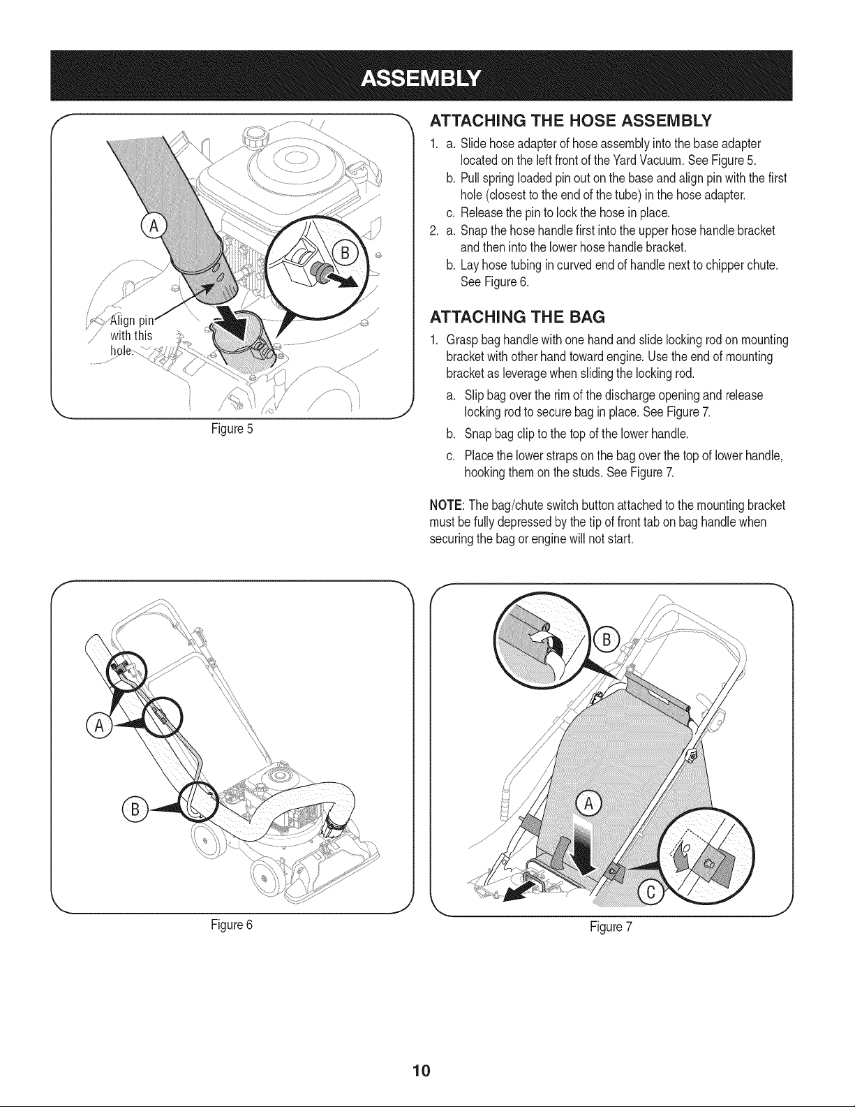
Figure5
_, ATTACHING THE HOSE ASSEMBLY
1. a. Slidehoseadapterof hoseassemblyintothe baseadapter
locatedon the leftfront of theYardVacuum.See Figure5.
b. Pullspringloadedpinout on the baseandalignpinwith the first
hole(closestto the end of the tube) in the hoseadapter.
c. Releasethe pinto lock the hosein place.
2. a. Snapthe hosehandlefirst intothe upperhose handlebracket
andthen intothe lowerhosehandlebracket.
b. Layhosetubingincurved endof handlenextto chipperchute.
SeeFigure6.
ATTACHING THE BAG
Graspbag handlewithonehand andslide lockingrodon mounting
bracketwith otherhandtowardengine.Usethe end of mounting
bracketas leveragewhenslidingthe lockingrod.
a. Slip bagoverthe rim of the dischargeopeningandrelease
lockingrodto securebag in place.SeeFigure7.
b. Snap bagclipto the topof the lowerhandle.
c. Placethe lowerstrapson the bag overthe topof lowerhandle,
hookingthemon the studs.See Figure7.
NOTE:The bag/chuteswitchbuttonattachedto the mountingbracket
must befully depressedby thetip of fronttab on bag handlewhen
securingthe bagorenginewill not start.
Figure6
Figure7
10
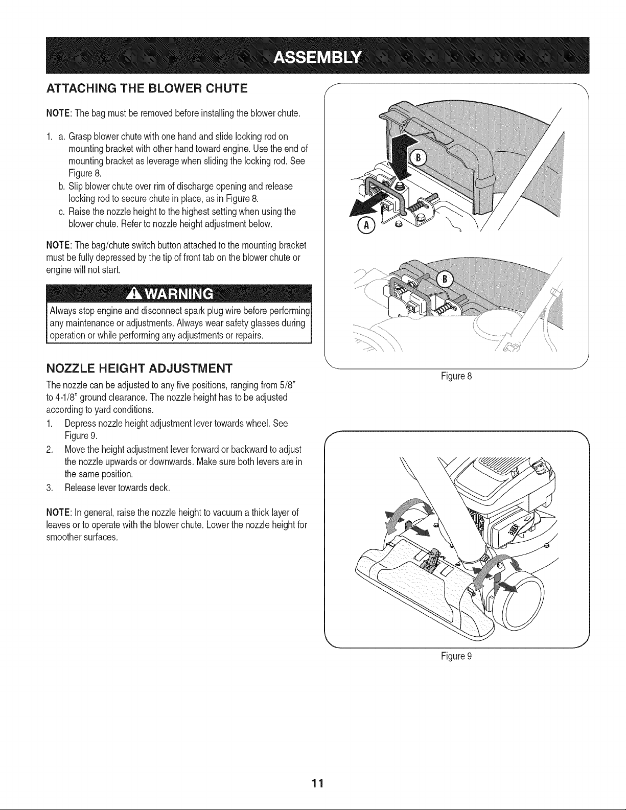
ATTACHING THE BLOWER CHUTE f
NOTE:Thebagmust be removedbeforeinstallingthe blowerchute.
1. a. Graspblowerchutewithone handand slide lockingrod on
mountingbracketwith otherhand towardengine.Usethe end of
mountingbracketas leveragewhenslidingthe lockingrod.See
Figure8.
b. Slipblowerchute overrimof dischargeopeningandrelease
lockingrodto securechute in place,as in Figure8.
c. Raisethe nozzleheightto the highestsettingwhen usingthe
blowerchute.Referto nozzleheightadjustmentbelow.
NOTE:Thebag/chuteswitchbuttonattachedto the mountingbracket
mustbe fullydepressedbythe tip of fronttab onthe blowerchuteor
enginewill not start.
Alwaysstop engineanddisconnectspark plugwire beforeperforming
any maintenanceor adjustments.Alwayswear safetyglassesduring
operationor whileperformingany adjustmentsor repairs.
NOZZLE HEIGHT ADJUSTMENT
Thenozzlecan be adjustedto anyfive positions,rangingfrom5/8"
to 4-1/8"groundclearance.The nozzleheighthasto be adjusted
accordingto yardconditions.
1. Depressnozzleheightadjustmentlevertowardswheel.See
Figure9.
2. Movethe heightadjustmentleverforwardor backwardto adjust
the nozzleupwardsordownwards.Makesure bothleversarein
the sameposition.
3. Releaselevertowardsdeck.
NOTE:In general,raisethe nozzleheightto vacuuma thicklayerof
leavesorto operatewiththeblowerchute.Lowerthe nozzleheightfor
smoothersurfaces.
f
\\
Figure8
J
Figure9
J
11
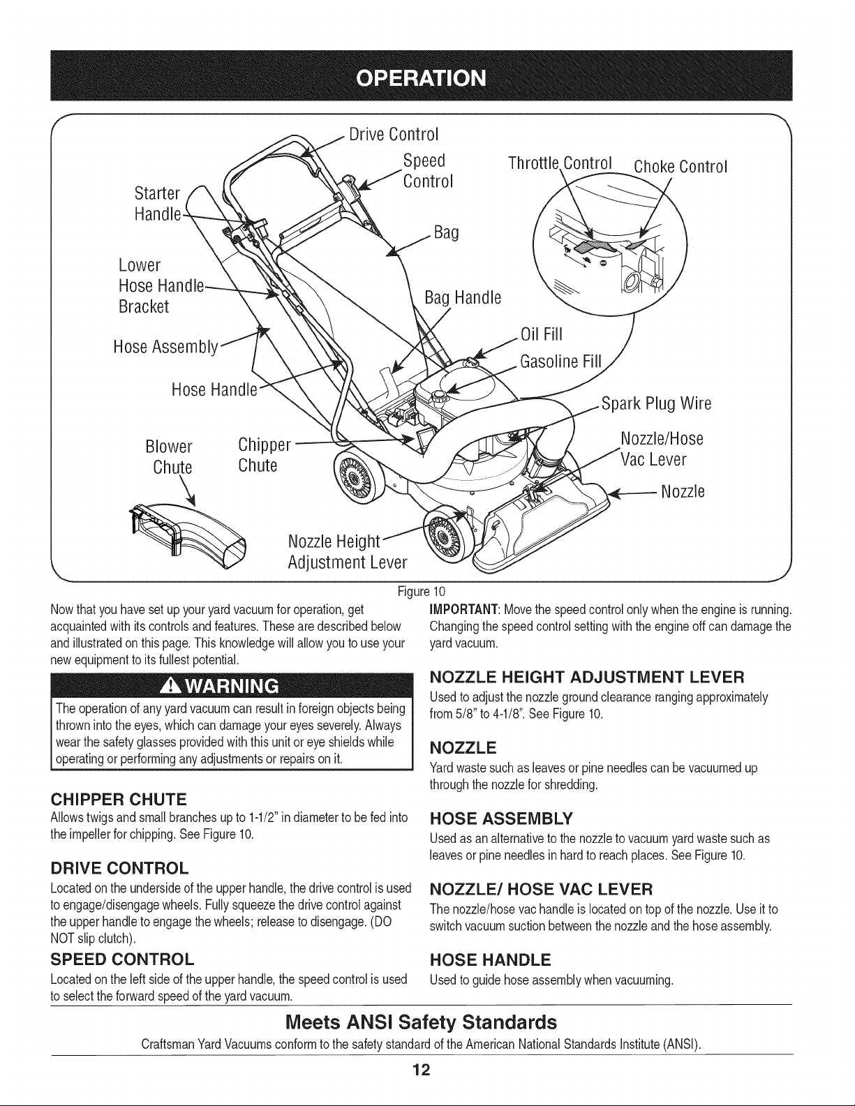
f
Drive Control
Speed Thr( Control Choke Control
Starter
Lower
Hose
Bracket
HoseAssembl'
Hose
Blower Chipper
Chute Chute
Bag
Bag Handle
Oil Fill
Gasoline Fill
)ark Plug Wire
Nozzle/Hose
Lever
Nozzle
Nowthat youhavesetup youryardvacuumfor operation,get
acquaintedwith itscontrolsand features.Theseare describedbelow
andillustratedon thispage.Thisknowledgewill allowyou to useyour
newequipmentto its fullestpotential.
Theoperationof anyyard vacuumcan resultinforeignobjectsbeing
thrownintothe eyes,whichcan damageyoureyesseverely.Always
I wearthe safetyglassesprovidedwiththis unit oreye shieldswhile
[operatingor performinganyadjustmentsor repairson it.
Nozzle Heig
Adjustment Lever
Figure10
iMPORTANT:Movethe speedcontrolonly whenthe engineis running.
Changingthe speedcontrolsettingwith theengineoff can damagethe
yardvacuum.
CHIPPER CHUTE
Allowstwigsand smallbranchesup to 1-1/2"in diameterto be fed into
the impellerfor chipping.See Figure10.
DRIVE CONTROL
Locatedon the undersideof the upperhandle,the drivecontrolis used
to engage/disengagewheels.Fullysqueezethe drivecontrolagainst
the upperhandleto engagethe wheels;releaseto disengage.(DO
NOTslip clutch).
SPEED CONTROL
Locatedon the leftside of the upperhandle,the speedcontrolis used
to selectthe forwardspeedof the yardvacuum.
NOZZLE HEIGHT ADJUSTMENT LEVER
Usedto adjustthe nozzlegroundclearancerangingapproximately
from5/8" to 4-1/8".See Figure10.
NOZZLE
Yardwastesuch as leavesorpineneedlescan bevacuumedup
throughthe nozzlefor shredding.
HOSE ASSEMBLY
Usedas analternativeto thenozzleto vacuumyardwastesuchas
leavesor pine needlesin hardto reachplaces.SeeFigure10.
NOZZLE/HOSE VAC LEVER
The nozzle/hosevachandleis locatedon topof the nozzle.Useit to
switchvacuumsuctionbetweenthe nozzleand the hoseassembly.
HOSE HANDLE
Usedto guidehoseassemblywhenvacuuming.
Meets ANSI Safety Standards
CraftsmanYardVacuumsconformto the safetystandardof the AmericanNationalStandardsinstitute(ANSi).
12
BAG HANDLE
Usedto grasp baginorderto assistin attaching,removing,and
emptyingbag.SeeFigure10.
BLOWER CHUTE
Whenattachedto unit,the blowerchute isusedto dischargeyard
wastesuchas leaves,pineneedle,or small twigsacrossyard.
THROTTLE CONTROL
Thethrottlecontrolsthe engine speedandstop function.Through
threeseparatepositionson the leverfromleftto right,the operationis
as follows:
Fast Slow Engine Off
CHOKE CONTROL
Thechokecontrol is usedto chokethe carburetorandassist instarting
the engine.
GAS AND OiL FILL-UP
Oil (one bottle shipped with unit)
First TimeUse
1. Removeoilfill dipstick.
2. With theYardVacuumon levelground,usea funnelto empty
entirecontentsof oil bottleprovidedintothe engine.
3. Replaceoil fill dipstickand tighten.
* Below40°F(4°C)the useof SAE30 will resultinhardstarting.
**Above80°F (27°C)the useof 10%30 may causeincreasedoil
consumption.Checkoillevelmorefrequently.
1. Checkthe oil withthe enginestoppedand level.
2. Removethe oilfill dipstick andwipeitclean.
3. Insertandtighten theoil fill dipstick.Removeitto checktheoil
level.
4. Ifthe oil levelisnearor belowthe lowerlimitmarkonthe dipstick,
removethe oilfill dipstick,andfill with the recommendedoil to the
upperlimitmark.Do notoverfill.
5. Reinstallthe oil fill dipstick.
Gasoline
Do not useunapprovedgasolines,suchas E85.Donot mix oil in
I gasolineor modifyengineto runonalternatefuels.Thiswilldamage
[the enginecomponentsandvoid the engine warranty.
Fuel must meetthese requirements:
• Clean,fresh, unleadedgasoline.
• A minimumof 87 octane/87AKI (91 RON).
• Gasolinewith up to 10%ethanol(gasohol)is acceptable.
Refuelina well-ventilatedareawith the enginestopped.If theengine
hasbeen running,allowitto cool first. Neverrefueltheengineinsidea
buildingwheregasolinefumesmay reachflamesor sparks.
Gasolineis highlyflammableand explosive,and you can be
burnedor seriouslyinjuredwhen rdueling. Stopengineandkeep
heat,sparks,and flame away.Refuelonlyoutdoors.Wipeup spills
immediately.
Subsequent Uses
Use4-strokemotoroil that meetsor exceedsthe requirementsfor
APIservicecategorySF,SG, SH, SJor higher.Alwayscheckthe API
servicelabelon the oil containerto besureit includesthe lettersSF,
SG,SH, SJor higher.
Outdoortemperaturesdeterminethe properoil viscosityfor the engine.
Usethechartto selectthe bestviscosityfor the outdoortemperature
r_..ge #xpected.
68 20
so _o
=_[_ 1._ [ o
s2,,
14 C _ '"t'x '_10
, °° I,
Ifyourequipmentwill be usedon an infrequentor intermittentbasis,
pleasereferto the Off SeasonStoragesectionfor additionalinforma-
tion regardingfuel deterioration.
NOTE:Fuelcan damagepaintandsometypesof plastic.Becareful
notto spill fuelwhenfillingyourfuel tank.
Neverusestale orcontaminatedgasolineor an oil/gasolinemixture.
Avoidgettingdirt or waterin thefuel tank.
1. Removethe fueltankcap.
2. Fillthe fueltankwith fuel.Toallowfor expansionof the fuel, do
notfill abovethe bottomof the fueltank neck.Do notoverfill.
Wipe upspilledfuelbeforestartingthe engine.
3. Installthe fuel tankcap andtightenit untilit clicks.
4. Moveyard vacuumat least10 feetawayfromthe fuel container/
sourceand sitebeforestartingthe engine.
NOTE:Checkthe fuellevel periodicallyto avoidrunningout of
gasolinewhile operatingthe yardvacuum.If the unit runsout of gas as
it is chipping,it maybe necessaryto unclogthe dischargeareabefore
it can berestarted.Referto SERVICEAND MAINTENANCEsection.
13
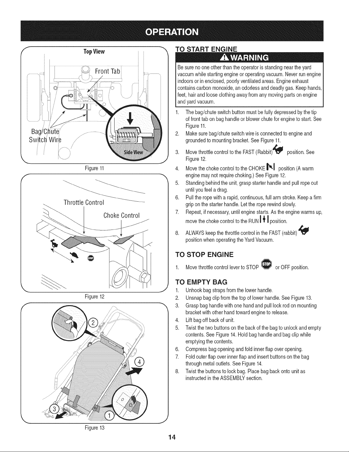
TopView
iiii FrontTab i i
BagYC_hutei/
Switch:Wire /
/
/
Figure11
Choke Control
Figure12
f
;/
TO START ENGINE
Besurenooneotherthan theoperatoris standingnearthe yard
vaccumwhilestartingengineoroperatingvacuum.Neverrunengine
indoorsor in enclosed,poorlyventilatedareas. Engineexhaust
containscarbonmonoxide,an odorlessand deadlygas. Keephands,
feet, hairand looseclothingawayfrom any movingpartson engine
andyardvacuum.
1. The bag/chuteswitch buttonmustbe fullydepressedbythe tip
of fronttab on baghandleor blowerchutefor engineto start.See
Figure11.
2. Makesurebag/chuteswitchwire is connectedto engineand
groundedto mountingbracket.SeeFigure11.
3. Movethrottlecontrolto the FAST(Rabbit)4_ position.See
Figure12.
4. Movethechokecontrol to the CHOKE_,1 position(Awarm
enginemaynot requirechoking.)See Figure12.
5. Standingbehindthe unit, graspstarterhandleandpull ropeout
until youfeel a drag.
6. Pullthe rope witha rapid,continuous,full arm stroke.Keepa firm
gripon the starterhandle.Letthe roperewindslowly.
7. Repeat,if necessary,untilenginestarts.As the enginewarmsup,
movethechokecontrolto the RUNI _' I position.
8. ALWAYSkeepthe throttlecontrolinthe FAST(rabbit)
positionwhenoperatingthe YardVacuum.
TO STOP ENGINE
1. Movethrottlecontrolleverto STOP or OFFposition.
TO EMPTY BAG
1. Unhookbag strapsfromthe lowerhandle.
2. Unsnapbagclip fromthetop of lowerhandle.See Figure13.
3. Graspbaghandlewith onehandand pull lock rodon mounting
bracketwith otherhandtowardengineto release.
4. Liftbagoff backof unit.
5. Twistthe two buttonson the back of the bagto unlockandempty
contents.SeeFigure14.Holdbag handleandbagclip while
emptyingthe contents.
6. Compressbagopeningand fold innerflap overopening.
7. Foldouter flapoverinner flapand insertbuttonsonthe bag
throughmetaloutlets.See Figure14.
8. Twistthe buttonsto lockbag.Placebag backonto unitas
instructedinthe ASSEMBLYsection.
Figure13
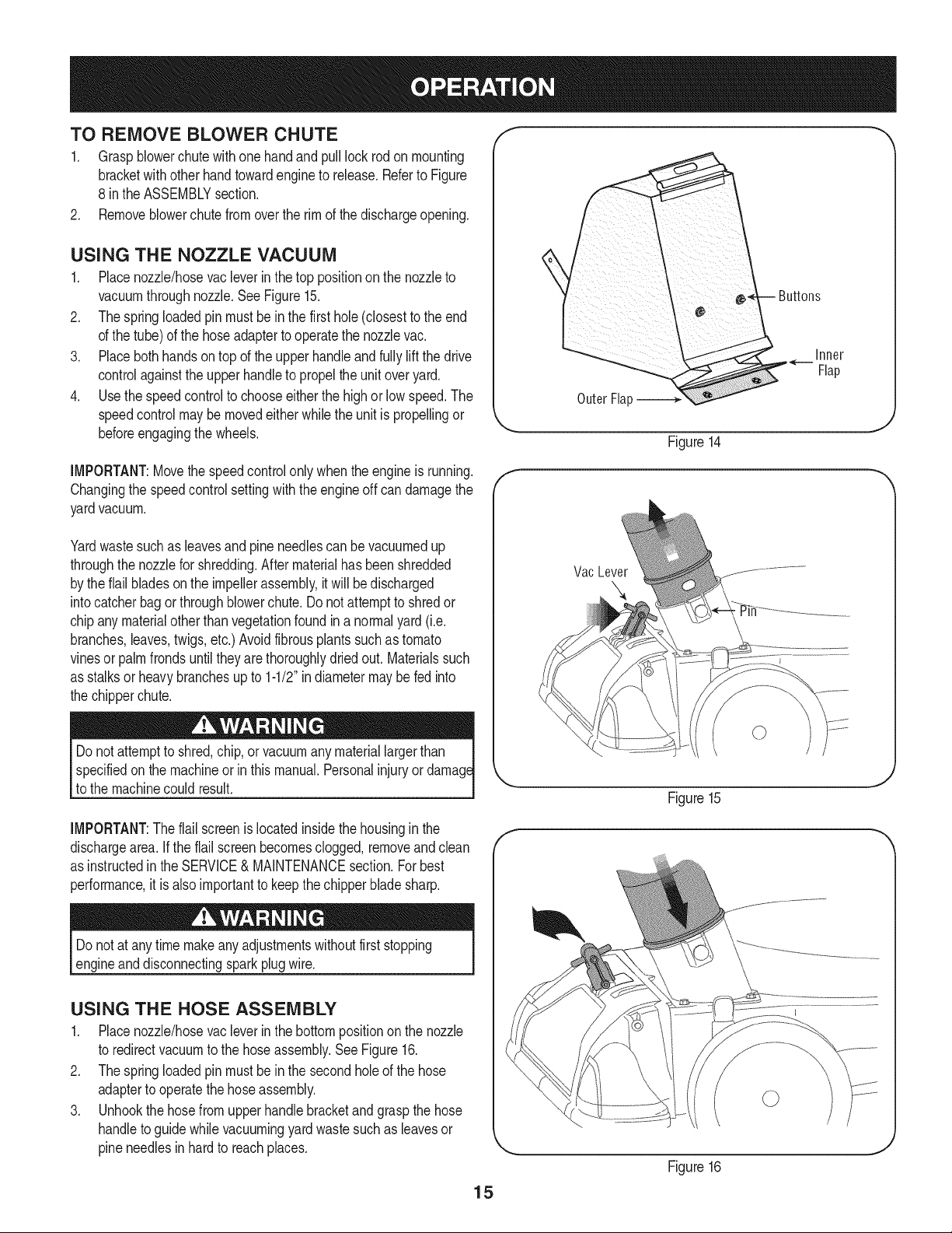
TO REMOVE BLOWER CHUTE
1. Graspblowerchute withone handand pull lock rodonmounting
bracketwith otherhandtowardengineto release.Referto Figure
8 inthe ASSEMBLYsection.
2. Removeblowerchutefromoverthe rim of the dischargeopening.
USING THE NOZZLE VACUUM
1. Placenozzle/hosevacleverinthe top positionon the nozzleto
vacuumthroughnozzle.SeeFigure15.
2. Thespringloadedpinmustbein the first hole(closestto the end
of the tube)of the hoseadapterto operatethe nozzlevac.
3. Placebothhandson top of the upper handleandfullylift the drive
controlagainstthe upperhandleto propel the unitoveryard.
4. Use the speedcontrolto chooseeitherthe highor low speed.The
speedcontrolmay bemovedeitherwhilethe unitis propellingor
beforeengagingthewheels.
IMPORTANT:Movethe speedcontrolonlywhenthe engineis running.
Changingthe speedcontrolsettingwith the engineoff candamagethe
yardvacuum.
Yardwastesuchas leavesand pineneedlescan be vacuumedup
throughthe nozzlefor shredding.After materialhas beenshredded
by theflail bladesonthe impellerassembly,it will be discharged
intocatcherbagor throughblowerchute.Do notattemptto shredor
chipany materialotherthan vegetationfoundin a normalyard(i.e.
branches,leaves,twigs,etc.)Avoidfibrousplantssuchas tomato
vinesor palmfronds untiltheyare thoroughlydriedout. Materialssuch
as stalksor heavybranchesupto 1-1/2"indiametermaybe fed into
the chipperchute.
specifiedonthe machineor in thismanual.Personalinjuryor
to the machinecould result.
IMPORTANT:Theflail screenis locatedinsidethe housinginthe
dischargearea. Ifthe flail screenbecomesclogged,removeand clean
as instructedin the SERVICE& MAINTENANCEsection.Forbest
performance,it is alsoimportantto keepthe chipperbladesharp.
Do notat any time makeanyadjustmentswithoutfirststopping
engineanddisconnectingspark plugwire.
USING THE HOSE ASSEMBLY
1. Placenozzle/hosevacleverinthe bottompositionon the nozzle
to redirectvacuumto the hoseassembly.See Figure16.
2. Thespringloadedpinmustbein the secondholeof the hose
adapterto operatethe hoseassembly.
3. Unhookthe hosefromupperhandlebracketand graspthe hose
handleto guidewhilevacuumingyardwastesuchas leavesor
pineneedlesin hardto reachplaces.
15
Inner
Flap
Outer Flap
Figure14
Vac Lever
Figure15
F
Figure16
MAINTENANCE SCHEDULE
Beforeperforminganytypeofmaintenance/service,disengageall
controlsandstoptheengine.Waituntilallmovingpartshavecometo
acompletestop.Disconnectsparkplugwireandgroundit toprevent
unintendedstarting.Alwayswearsafetyglassesduringoperationor while
performinganyadjustmentsorrepairs.
Followthe maintenanceschedulegiven below.Thischart describes
serviceguidelinesonly. Usethe ServiceLogcolumnto keeptrackof
completedmaintenancetasks.To locate the nearest Sears Service
Centeror to scheduleservice,simplycontactSearsat
1-800-4-MY-HOME®.
EachUse
1st5 hours
Annuallyor 25hours
Annuallyor 50hours
Annually
BeforeStorage
.
2.
3.
1.
1.
2.
3.
1.
1.
2.
1.
Engineoillevel
Looseor missinghardware
Unitandengine.
Engineoil
Aircleaned-
Controllinkages/pivotsandwheels
Undersideof mowerdeck
Engineoil
Sparkplug
AirCleaner
Fuelsystem
Cleanmoreoftenunderdustyconditionsor whenairbornedebrisis
1. Check
2. Tightenor replace
3. Clean
1. Change
1. Clean
2. Lubewith light oil
3. Clean
1. Change
1. Replace
2. Replace
1. Runengineuntil it stopsfromlackof
fuel,oradd stabilizerto a full tank of
freshfuel priorto storage.
_resent.Replaceair cleanerif very dirty.
Alwaysstopengineand disconnectsparkplugwire beforeperforming
I anymaintenanceor adjustments.Alwayswear safetyglassesduring
_operationor whileperforminganyadjustmentsor repairs.
GENERAL RECOMMENDATIONS
• Alwaysobservesafetyruleswhenperforming
anymaintenance.
• Thewarrantyon thisyardvacuumdoes notcoveritemsthat have
beensubjectedto operatorabuseor negligence.To receivefull
valuefromwarranty,operatormustmaintaintheequipmentas
instructedhere.
• Someadjustmentswillhaveto be madeperiodicallyto maintain
yourunit properly.
• Periodicallycheckall fastenersand makesurethesearetight.
ENGINE MAINTENANCE
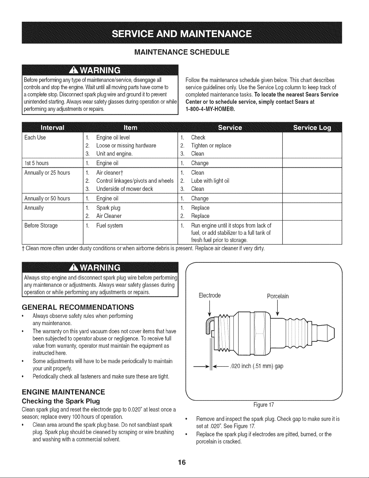
Checking the Spark Plug
Cleansparkplug andresettheelectrodegapto 0.020"at leastonce a
season;replaceevery100hoursof operation.
Cleanareaaroundthe spark plugbase.Do not sandblastspark
plug.Sparkplugshouldbecleanedby scrapingor wire brushing
andwashingwith a commercialsolvent.
f
Electrode
Porcelain
.020 inch (.51 ram) gap
J
Figure17
Removeand inspectthe sparkplug.Checkgapto makesureit is
setat .020".SeeFigure17.
• Replacethe sparkplugif electrodesare pitted,burned,or the
porcelainis cracked.
16
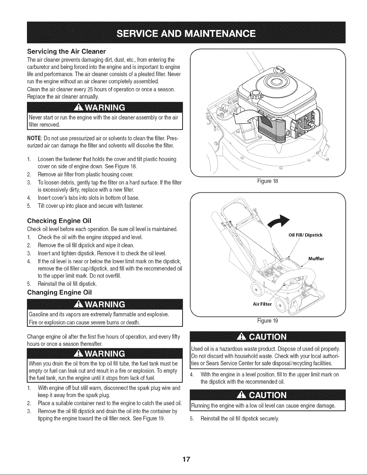
Servicing the Air Cleaner
Theair cleanerpreventsdamagingdirt, dust,etc.,fromenteringthe
carburetorand beingforcedintothe engineandis importantto engine
life andperformance.Theair cleanerconsistsof a pleatedfilter. Never
runthe enginewithoutan air cleanercompletelyassembled.
Cleantheair cleanerevery 25hoursof operationoronce a season.
Replacetheair cleanerannually.
Neverstartor run the enginewiththe air cleanerassemblyor theair
filterremoved.
NOTE:Do notuse pressurizedairor solventsto cleanthe filter.Pres-
surizedair can damagethefilterand solventswill dissolvethefilter.
1. Loosenthe fastenerthatholdsthe coverand tilt plastichousing
coveron sideof enginedown.See Figure18.
2. Removeairfilterfrom plastichousingcover.
3. Toloosendebris,gentlytap the filter ona hardsurface.If the filter
is excessivelydirty, replacewith a newfilter.
4. Insertcover'stabsinto slotsin bottomof base.
5. Tilt coverupinto placeand securewithfastener.
Checking Engine Oil
Checkoil levelbeforeeachoperation.Be sureoil levelis maintained.
1. Checktheoil with the enginestoppedand level.
2. Removetheoil fill dipstickand wipe it clean.
3. Insertandtightendipstick.Removeit to checktheoil level.
4. If theoil levelis near or belowthe lowerlimit markon the dipstick,
removethe oil fillercap/dipstick,andfill with the recommendedoil
to the upperlimitmark. Donotoverfill.
5. Reinstallthe oil fill dipstick.
Changing Engine Oil
Gasolineandits vaporsareextremelyflammableandexplosive.
Fireor explosioncancausesevereburnsordeath.
Oil Fill/Dipstick
/
Mumer
/
Figure19
Changeengineoil afterthe first fivehoursof operation,andevery fifty
hoursor once a seasonthereafter.
Whenyou drain theoil fromthe top oil fill tube,the fuel tankmustbe
I emptyor fuel can leakoutand resultin a fire or explosion.Toempty
Ithe fuel tank, runthe engine untilit stopsfrom lackof fuel.
1. With engineoffbut stillwarm,disconnectthe sparkplugwire and
keepit awayfrom the sparkplug.
2. Placea suitablecontainernextto theengineto catchthe usedoil.
3. Removetheoil fill dipstickand draintheoil intothe containerby
tippingtheenginetowardthe oil fillerneck.See Figure19.
Usedoil is a hazardouswasteproduct.Disposeof usedoil properly.
IDo notdiscardwithhouseholdwaste.Checkwithyour localauthori-
_tiesorSearsServiceCenterfor safe disposal/recyclingfacilities.
4. With the enginein a levelposition,fill to the upperlimit markon
the dipstickwiththe recommendedoil.
Runningtheenginewitha low oil levelcan causeengine damage.
5. Reinstallthe oil fill dipsticksecurely.
17

Cleaning Engine
• Dailyor beforeevery use,cleangrass,chaffor accumulated
debrisfromengine.Keeplinkage,spring,andcontrolsclean.
Keepareaaroundandbehindmufflerfreeof any combustible
debris.
• Keepingenginecleanallowsairmovementaroundengine.
• Enginepartsshouldbe keptcleanto reducethe risk of overheat-
ingandignitionof accumulateddebris.
Do not usewaterto cleanengineparts.Watercouldcontaminatefuel
system.Usea brushor drycloth.
LUBRICATION
* Wheels- Placea few dropsof SAE30 oilon eachshoulderscrew
oncea season.
, Nozzle heightadjustment levers-Lubricatenozzleheight
adjustmentleverswith lightoil.
, Locking Rod- Lubricatethe lock rodandcompressionsprings
whichattachto the mountingbracket.
, Nozzle/HoseVac Lever: Lubricatethe nozzle/hosevac leveron
topof the nozzleonce a seasonwithlightoil.
Figure20
CLEANING EQUIPMENT
Cleanundersideof theyardvacuumonce a seasonto preventbuild-up
of debris.Followstepsbelowfor thisjob.
1. Disconnectandground sparkplugwire.Emptythe fueltankby
runningengineuntiltank is dry.
2. Tipthe yard vacuumso that it restson itsside, keepingthe
mufflersidedown.Holdyardvacuumfirmly.
3. Scrapeandcleanthe undersideof the deck andnozzlewitha
suitabletool.Donot spraywithwater.
IMPORTANT:Donot usea pressurewasheror gardenhoseto clean
yourunit. Thesemaycausedamageto bearings,or the engine.The
useof water will resultin shortenedlife andreduceserviceability.
4. Putthe yardvacuumbackon its wheelson theground.
CLEANING THE FLAIL SCREEN
Ifthe dischargeareabecomesclogged,removetheflail screenand
cleanarea as follows:
1. Stopthe engine.Makecertainthe chipper/shreddervacuumhas
cometo a completestop.
2. Beforeuncloggingthe dischargechute,disconnect and ground
the spark plugwire.
3. Removethe vacuumbagor blowerchutefromthe unitas
instructedin the OPERATIONsectionto obtainaccessto flail
screen.
4. Removethe three selftappingscrewssecuringthebelt cover,and
removebeltcover.SeeFigure20.
5. Removeselftappingscrewon rightsideof unitthatattachesto
theflail screen.SeeFigure21.
f
/
Figure21
J
18
6. Removehexscrewontop of rear housingnearmountingbracket
andthe flangelocknutthatsecuresflail screen.SeeFigure21.
7. Removeandcleanthe screenby scrapingor washingwithwater.
SeeFigure22.
8. Reinstallthe screen.
Beforeperforminganytypeof maintenanceon the machine,wait for
all partsto stopmovingand disconnectandgroundthe sparkplug
wire. Failureto follow thisinstructioncould resultin personalinjuryor
propertydamage.
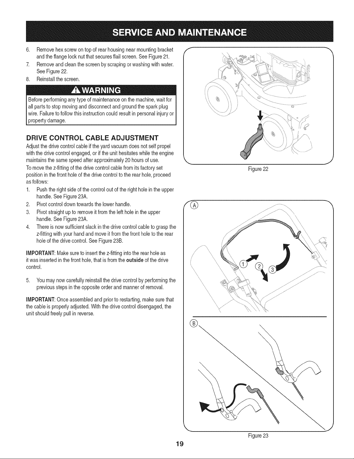
DRIVE CONTROL CABLE ADJUSTMENT
Adjustthe drivecontrolcableif theyard vacuumdoes not self propel
withthe drivecontrolengaged,orif the unithesitateswhilethe engine
maintainsthe same speedafterapproximately20 hoursof use.
Tomovethe z-fittingof the drivecontrolcablefromitsfactory set
positioninthe fronthole of the drivecontrolto the rear hole,proceed
as follows:
1. Pushthe rightsideof thecontroloutof the righthole inthe upper
handle.SeeFigure23A.
2. Pivotcontroldowntowardsthe lowerhandle.
3. Pivotstraightupto removeit from the left holein the upper
handle.SeeFigure23A.
4. Thereis nowsufficientslackinthe drivecontrolcableto graspthe
z-fittingwithyourhandandmoveit from the frontholeto the rear
holeof the drivecontrol.SeeFigure23B.
IMPORTANT:Makesureto insertthe z-fittingintothe rearholeas
it wasinsertedin the front hole,that is fromthe outside of the drive
control.
5. Youmay nowcarefullyreinstallthe drivecontrolby performingthe
previoussteps inthe oppositeorder andmannerof removal.
IMPORTANT:Onceassembledand priorto restarting,makesurethat
the cableis properlyadjusted.Withthe drivecontroldisengaged,the
unit shouldfreelypull in reverse.
f
\
Figure22
\
19
Figure23
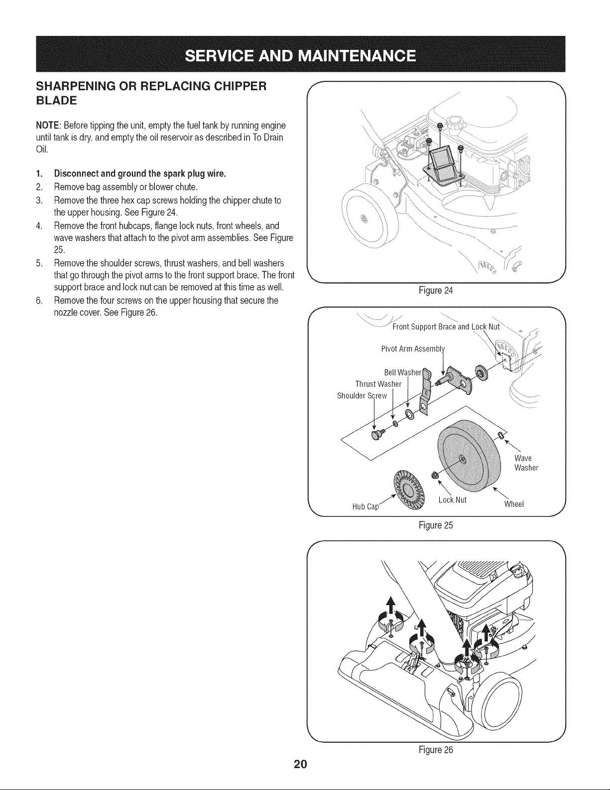
SHARPENING OR REPLACING CHIPPER
BLADE
NOTE:Beforetippingthe unit, emptythefuel tankby runningengine
untiltank isdry, andemptythe oil reservoiras describedinTo Drain
Oil.
1. Disconnectand groundthe sparkplugwire.
2. Removebagassemblyor blowerchute.
3. Removethe three hexcap screwsholdingthe chipperchuteto
the upperhousing.SeeFigure24.
4. Removethe fronthubcaps,flangelock nuts,front wheels,and
wavewashersthatattachto the pivotarm assemblies.See Figure
25.
5. Removethe shoulderscrews,thrustwashers,andbellwashers
thatgothroughthe pivotarmsto the frontsupportbrace.The front
supportbraceand locknut can beremovedat this time as well.
6. Removethe four screwson the upperhousingthat securethe
nozzlecover.SeeFigure26.
f
Figure24
x /
..........................Front support Brace and Lock Nui
Pivot Arm Assembl'
J
Bell Washer
Thrust Washer
Shoulder Screw
Wave
Washer
Lock Nut
Hub Ca[ Wheel
J
Figure25
f
2O
Figure26
J
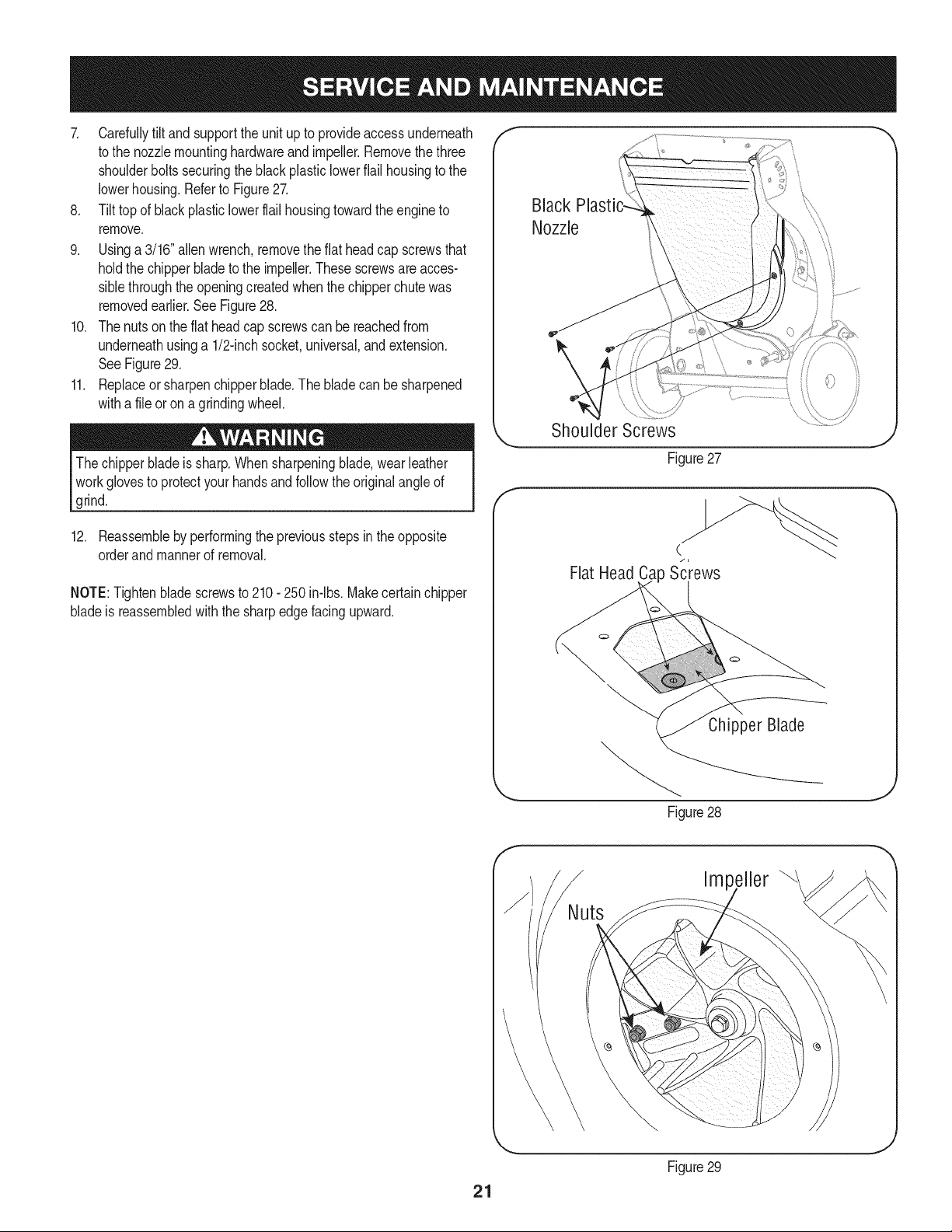
7. Carefullytilt andsupportthe unit up to provideaccessunderneath
to the nozzlemountinghardwareand impeller.Removethe three
shoulderboltssecuringthe blackplasticlowerflail housingto the
lowerhousing.Referto Figure27.
8. Tilt top of black plasticlowerflail housingtowardthe engineto
remove.
9. Usinga 3/16"allen wrench,removetheflat headcap screwsthat
holdthe chipperblade to the impeller.Thesescrewsareacces-
siblethroughtheopeningcreatedwhenthechipperchutewas
removedearlier.See Figure28.
10. Thenutson the flat headcap screwscan be reachedfrom
underneathusinga 1/2-inchsocket,universal,andextension.
SeeFigure29.
11. Replaceor sharpenchipperblade.The bladecan be sharpened
witha fileor ona grindingwheel.
The chipperbladeis sharp.Whensharpeningblade,wear leather
workglovesto protectyourhandsandfollowthe originalangleof
grind.
12. Reassembleby performingthe previousstepsin theopposite
orderand mannerof removal.
NOTE:Tightenbladescrewsto 210- 250 in-lbs.Makecertainchipper
bladeis reassembledwiththe sharpedgefacingupward.
Black
Nozzle
\
f
Shoulder Screws
Figure27
C
Flat Head Ca Screws
Chipper Blade
Figure28
J
Impeller
21
Figure29
J
Neverstoreyardvacuumwithfuel intank indoorsor in poorly
ventilatedareaswherefuel fumesmayreachan openflame,spark,
or pilotlight as on a furnace,water heater,clothesdryer,or gas
appliance.
PREPARING THE ENGINE
Forenginesstoredover30 days:
1. To preventgumfromformingin fuel systemor oncarburetor
parts, runengineuntilit stopsfrom lackof fuelor add a gasoline
additiveto the gas inthe tank. Ifyou usea gas additive,run the
enginefor severalminutesto circulatethe additivethroughthe
carburetor--afterwhichthe engineandfuel can bestoredup to
six months.
2. Whileengineis stillwarm,changethe oil.
3. Cleanengineof surfacedebris.
PREPARING THE YARD VACUUM
• Whenstoringthe yardvacuumin an unventilatedor metalstorage
shed,careshouldbe takento rustproofthe non-paintedsurfaces.
Usinga lightoil or silicone,coat the equipment,especiallyany
springs,bearings,andcables.
• Cleanandlubricatemowerthoroughlyas describedinthe lubrica-
tion instructions.
• Donot usea pressurewasheror gardenhoseto cleanyour unit.
• Store mowerin a dry,cleanarea. Do notstore nextto corrosive
materials,suchas fertilizer.
22
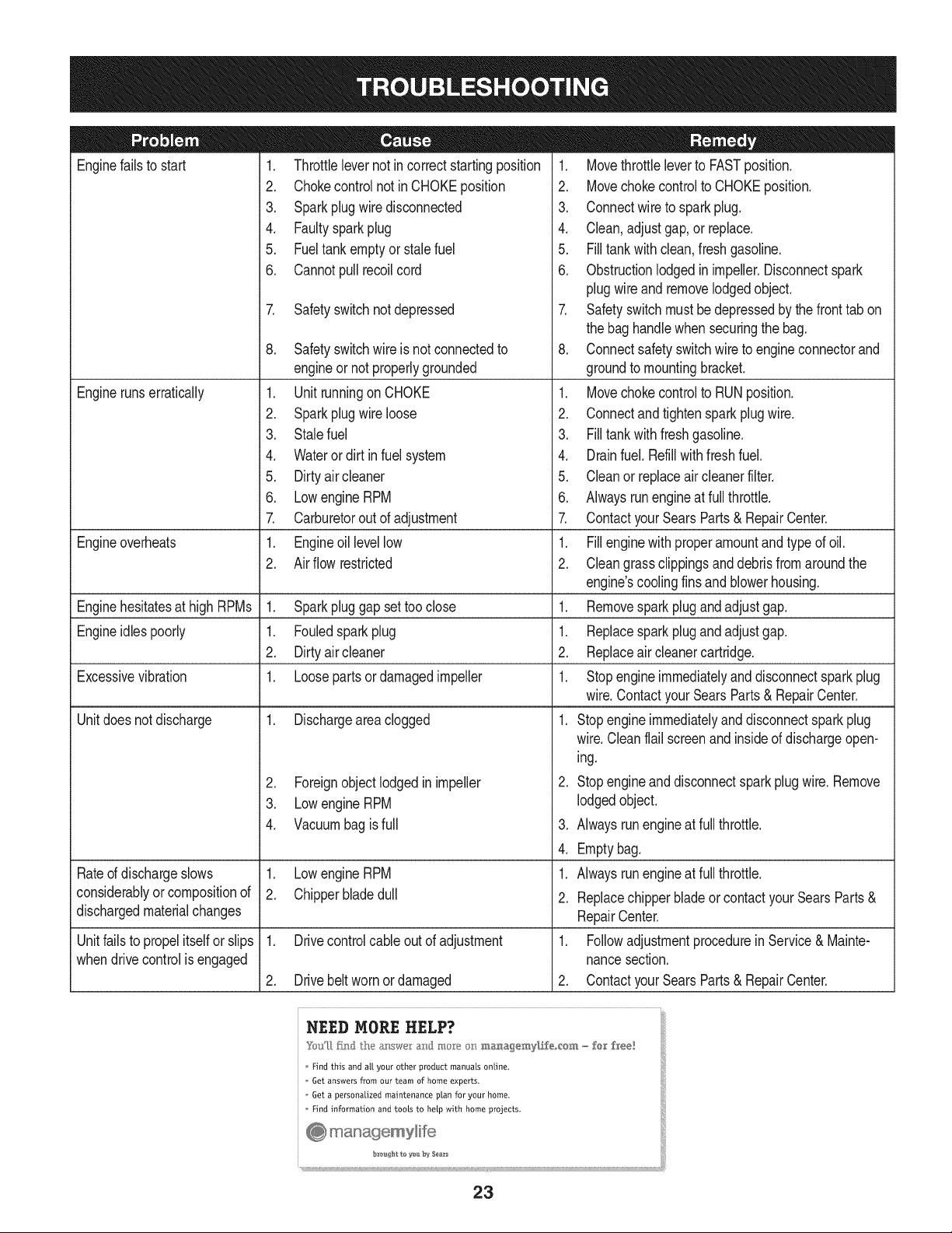
Enginefailsto start
Enginerunserratically
1. Throttlelevernot in correctstartingposition
2. Chokecontrolnot in CHOKEposition
3. Sparkplugwire disconnected
4. Faultysparkplug
5. Fueltank emptyorstale fuel
6. Cannotpull recoilcord
7. Safetyswitchnotdepressed
Engineoverheats
Enginehesitatesat high RPMs 1. Sparkpluggap settoo close
Engineidlespoorly 1. Fouledsparkplug
2. Dirtyair cleaner
Excessivevibration 1. Loosepartsor damagedimpeller
Unitdoesnot discharge 1. Dischargeareaclogged
Rated dischargeslows
considerablyor compositionof
dischargedmaterialchanges
Unitfails to propelitself or slips
whendrivecontrolisengaged
8. Safetyswitchwire is not connectedto
engineor notproperlygrounded
1. Unit runningon CHOKE
2. Sparkplugwire loose
3. Stalefuel
4. Wateror dirt in fuel system
5. Dirtyair cleaner
6. Lowengine RPM
7. Carburetorout of adjustment
1. Engineoil levellow
2. Air flow restricted
2. Foreignobjectlodgedin impeller
3. Lowengine RPM
4. Vacuumbagis full
1. Lowengine RPM
2. Chipperbladedull
1. Drivecontrolcableout of adjustment
2. Drivebeltworn ordamaged
1. Movethrottleleverto FASTposition.
2. Movechokecontrolto CHOKEposition.
3. Connectwire to sparkplug.
4. Clean,adjustgap,or replace.
5. Filltankwith clean,freshgasoline.
6. Obstructionlodgedin impeller.Disconnectspark
plugwire andremovelodgedobject.
7. Safetyswitchmustbedepressedby thefronttab on
the bag handlewhen securingthe bag.
8. Connectsafetyswitchwireto engineconnectorand
groundto mountingbracket.
1. Movechokecontrolto RUNposition.
2. Connectandtightensparkplugwire.
3. Filltankwith freshgasoline.
4. Drainfuel. Refillwithfreshfuel.
5. Cleanor replaceair cleanerfilter.
6. Alwaysrunengineat full throttle.
7. ContactyourSearsParts& RepairCenter.
1. Fillenginewith properamountandtype of oil.
2. Cleangrassclippingsanddebrisfromaroundthe
engine'scoolingfinsand blowerhousing.
1. Removesparkplug andadjustgap.
1. Replacespark plugandadjustgap.
2. Replaceair cleanercartridge.
1. Stopengineimmediatelyanddisconnectsparkplug
wire.ContactyourSearsParts & RepairCenter.
1. Stopengineimmediatelyanddisconnectsparkplug
wire.Cleanflail screenandinsideof dischargeopen-
ing.
2. Stopengineanddisconnectspark plugwire.Remove
lodgedobject.
3. Alwaysrunengineat full throttle.
4. Emptybag.
1. Alwaysrunengineat full throttle.
2. Replacechipperbladeor contactyourSearsParts &
RepairCenter.
1. Followadjustmentprocedurein Service& Mainte-
nancesection.
2. ContactyourSearsParts& RepairCenter.
Find this and all your other product manuals online.
Get answers from our team of home experts.
Get a personalized maintenance plan for your home.
Find information and tools to heLp with home projects.
23
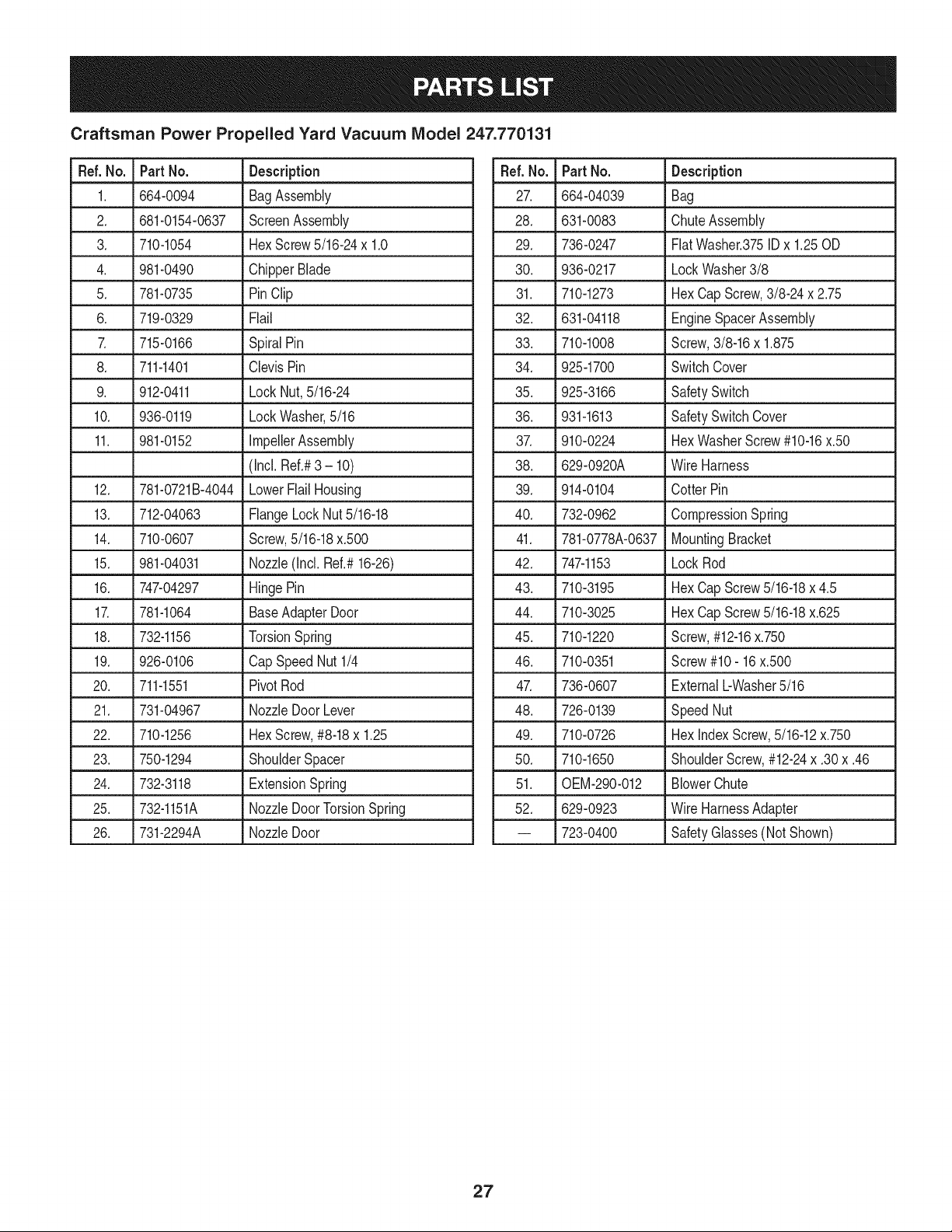
Craftsman Power Propelled Yard Vacuum Model No. 247.770131
14
44
41
54
63
38
24
Ref. No. Part No. Description
1. 731-07001 HubCap
2. 749-04163-0637 UpperHandle
3. 720-0279 Knob
4. 710-1205 EyeBolt
5. 781-1056-0637 UpperHandleBracket
6. 710-0726 Hex CapScrew5/16-12x.750
7. 720-04072A HandleKnob5/16-18
8. 710-1174 CarriageBolt
9. 731-04911 NozzleHandleClip
10. 749-04165-0637 LowerHandle
11. 711-1293 Studs
12. 710-0703 CarriageScrew1/4-20x.75
13. 712-0397A Wing Nut1/4-20
14. 710-1611B TT Screw,5/16-18x .750
15. 710-05073 Screw,1/4-20x .500
16. 912-0442 CapLock Nut, 1/4-20
17. 710-0751 HexCapScrew1/4-20x.620
18. 681-0195 HoseBaseAdapterAssembly
(Incl.Ref.#19-21)
19. 916-0104 E Ring.500Dia
20. 932-3035 CompressionSpring
21. 711-1571 ClevisPin
22. 936-3020 FiatWasher.271ID x.630OD
23. 781-04266-4044 UpperFlailHousing
24. 746-04156 DriveControlCable
25. 731-1820 CableGuide
26. 681-04088-4044 ChipperChuteAssembly
27. 746-04155 SpeedControlCable
28. 710-1122 Hex Screw,1/4-20x 2.50
29. 981-0156A-4044 HandleBracketAss'yRH
981-0155A-4044 HandleBrktAss'y LH(NotShown)
30. 717-1762 SpurGear- RH
717-1761 SpurGear- LH (Not Shown)
31. 748-0457 Spacer
32. 731-2478 HoseNozzle
33. 710-3288 Hex CapScrew 1/4-20x 2.625
34. 723-0295 AdjustmentClamp
35. 749-1270A NozzleHandle
36. 764-0648A VacuumHose
37. 720-0369 HandlePlug
38. 731-2292 HoseAdapter
39. 747-04305A DriveControl
Ref.No. Part No. Description
40. 725-0157 CableTie
41. 918-04460 TransmissionAssembly
42. 732-04217 ExtensionSpring,.375x 2.95
43. 710-1650 ShoulderScrew,#12-24x .30x .46
44. 710-1220 Screw,#12-16x .750
45. 911-04245 ImpellerHub
46. 915-0221 DowelPin
47. 781-04082-0637 FrontWheelSupportBrace
48. 781-04081-0637 RearWheelSupportBrace
49. 914-0104 CotterPin
50. 916-0104 E-Ring
51. 936-3004 Fiat Washer,.406x .875x .105
52. 712-04217 Nut, Flglk.,3/8-16
53. 738-04523 ShoulderScrew,.496x 1.605
54. 734-04596 RearWheel
55. 716-0865 SnapRing
56. 741-04242 HeightAdjustmentBearing
57. 681-04195 PivotArm Assembly
58. 720-0426 HeightAdjustmentKnob
59. 732-1026 Spring Lever
60. 736-0741 Bell Washer.760ID x.25OD
61. 738-1172 ShoulderScrew,.750x.500
62. 987-02051 HeightLeverAssy(Incl. Ref.#58-59)
63. 734-04568 FrontWheel
64. 710-1652 Screw,1/4-20x .625
65. 712-04065 FlangeLock Nut,3/8-16
66. 731-04879 Belt Cover
67. 936-0314 ThrustWasher.375IDx.70OD
68. 731-04643 WheelCover
69. 936-0369 Fiat Washer,.5081Dxl .O00Dx.020
70. 738-0930 ShoulderScrew,.560x.165
71. 741-04108 DriveAxle Bushing
72. 781-04078-0637 TransmissionMountingBracket
73. 710-0597 Screw,1/4-20x 1.00
74. 712-04064 FlangeLock Nut,1/4-20
75. 941-0600 Ball Bearing
76. 750-1050 FlangeSpacer,.260x.659x.517
77. 954-0369 Belt,3/8 x 32.5
78. 781-04077-0637 Idler Bracket
79. 782-7598 Belt Keeper
80. 126MO2-O434-F1Engine
25
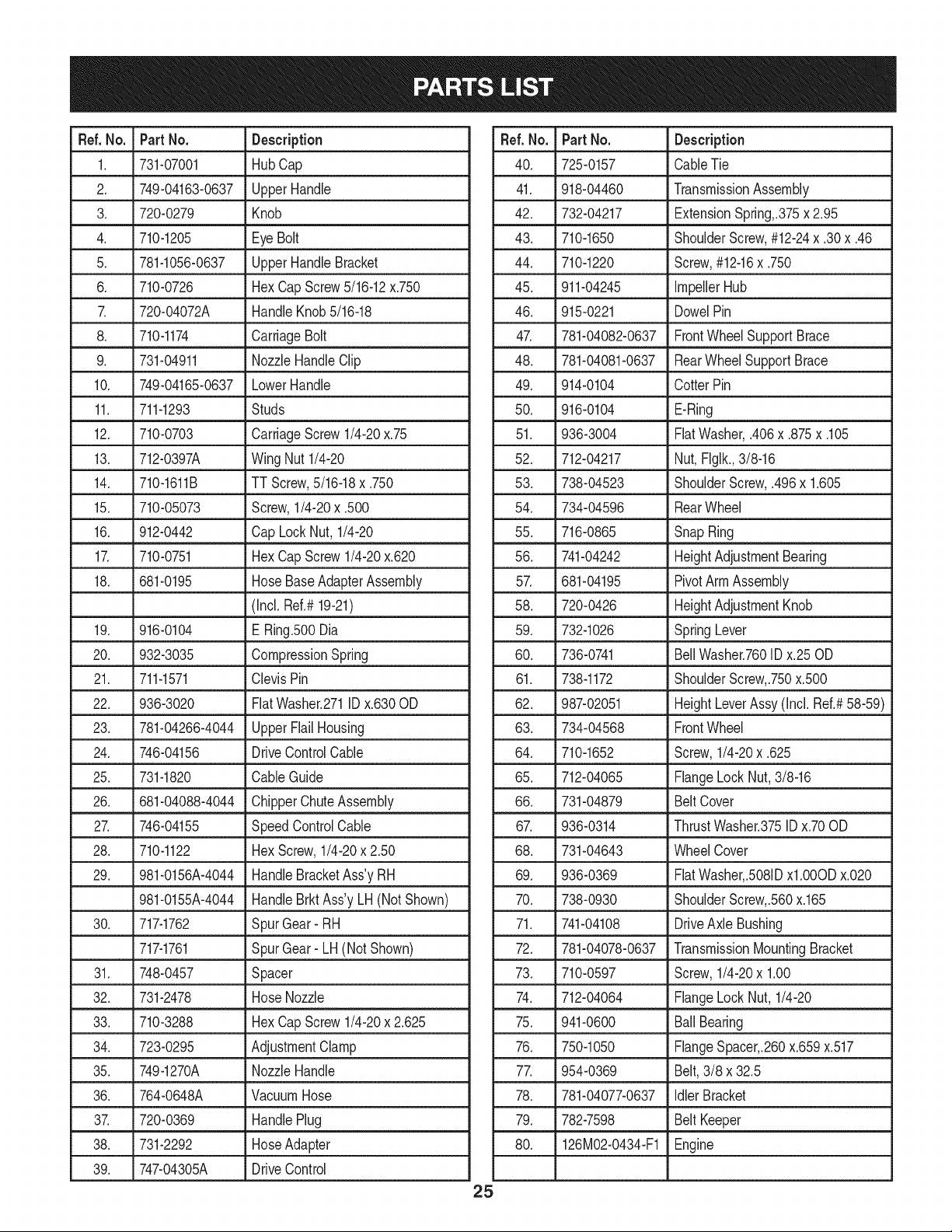
Craftsman Power Propelled Yard Vacuum Model 247.770131
[]
45
7
6
30/i_31
[]
25
26
Craftsman Power Propelled Yard Vacuum IViodel 247.770131
Ref. No. Part No. Description
1. 664-0094 BagAssembly
2. 681-0154-0637 ScreenAssembly
3. 710-1054 HexScrew5/16-24x 1.0
4. 981-0490 ChipperBlade
5. 781-0735 PinClip
6. 719-0329 Flail
7. 715-0166 SpiralPin
8. 711-1401 ClevisPin
9. 912-0411 LockNut,5/16-24
10. 936-0119 LockWasher,5/16
11. 981-0152 ImpellerAssembly
(Incl.Ref.#3 - 10)
12. 781-0721B-4044 LowerFlailHousing
13. 712-04063 FlangeLockNut 5/16-18
14. 710-0607 Screw,5/16-18x.500
15. 981-04031 Nozzle(Incl. Ref.#16-26)
16. 747-04297 HingePin
17. 781-1064 BaseAdapterDoor
18. 732-1156 TorsionSpring
19. 926-0106 CapSpeed Nut1/4
20. 711-1551 PivotRod
21. 731-04967 NozzleDoor Lever
22. 710-1256 HexScrew,#8-18x 1.25
23. 750-1294 ShoulderSpacer
24. 732-3118 ExtensionSpring
25. 732-1151A NozzleDoorTorsionSpring
26. 731-2294A NozzleDoor
Ref.No. Part No. Description
27. 664-04039 Bag
28. 631-0083 ChuteAssembly
29. 736-0247 FiatWasher.375IDx 1.25OD
30. 936-0217 LockWasher3/8
31. 710-1273 HexCap Screw,3/8-24 x 2.75
32. 631-04118 EngineSpacerAssembly
33. 710-1008 Screw,3/8-16x 1.875
34. 925-1700 SwitchCover
35. 925-3166 SafetySwitch
36. 931-1613 SafetySwitchCover
37. 910-0224 HexWasherScrew#10-16x.50
38. 629-0920A Wire Harness
39. 914-0104 CotterPin
40. 732-0962 CompressionSpring
41. 781-0778A-0637 MountingBracket
42. 747-1153 LockRod
43. 710-3195 HexCap Screw5/16-18x 4.5
44. 710-3025 HexCap Screw5/16-18x.625
45. 710-1220 Screw,#12-16x.750
46. 710-0351 Screw#10- 16x.500
47. 736-0607 ExternalbWasher5/16
48. 726-0139 SpeedNut
49. 710-0726 HexindexScrew,5/16-12x.750
50. 710-1650 ShoulderScrew,#12-24x .30x .46
51. 0EM-290-012 BlowerChute
52. 629-0923 Wire HarnessAdapter
-- 723-0400 SafetyGlasses(NotShown)
27
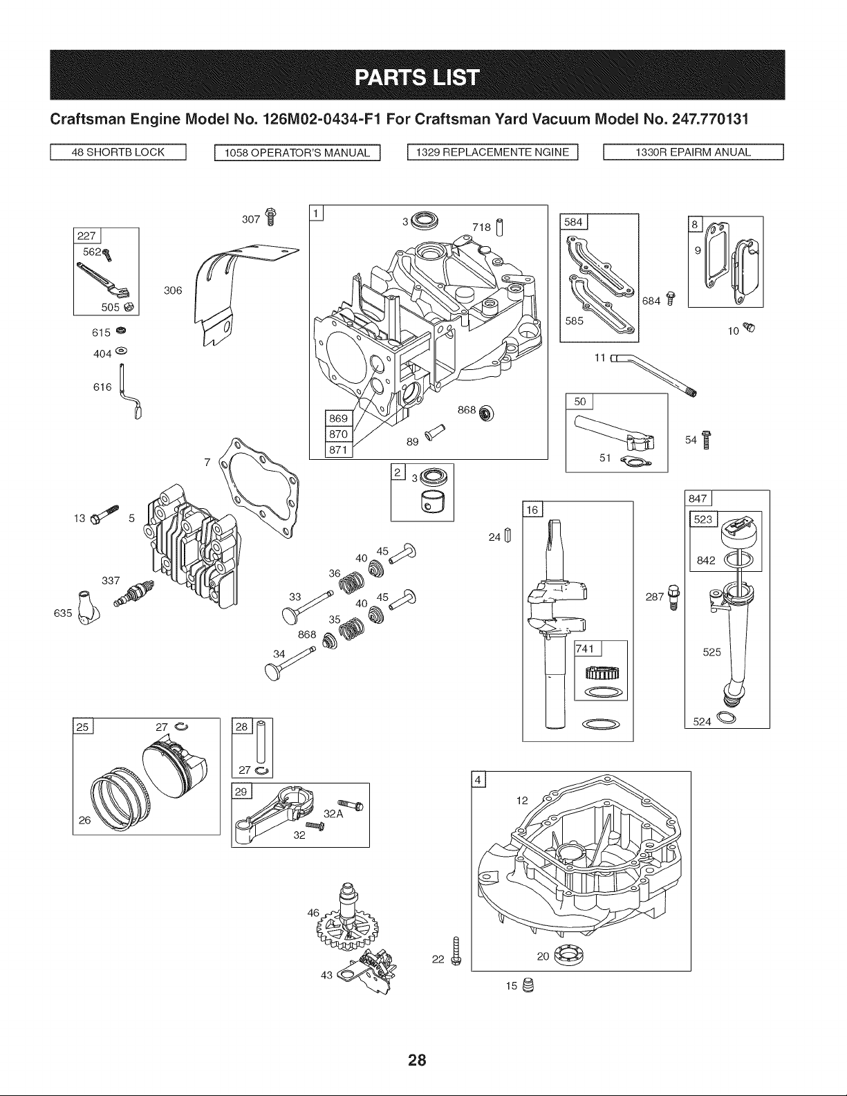
Craftsman Engine Model No. 126M02=0434=F1 For Craftsman Yard Vacuum Model No. 247.770131
I%
15o5
615
635
306
404 @
616
7_
307
3@
718 [_
©
241_
36_0_ 5_
33/.._ 40 45_:9d_
(_ 35_
868 _) _._
54
I}
524
287
4--]
20
158
28
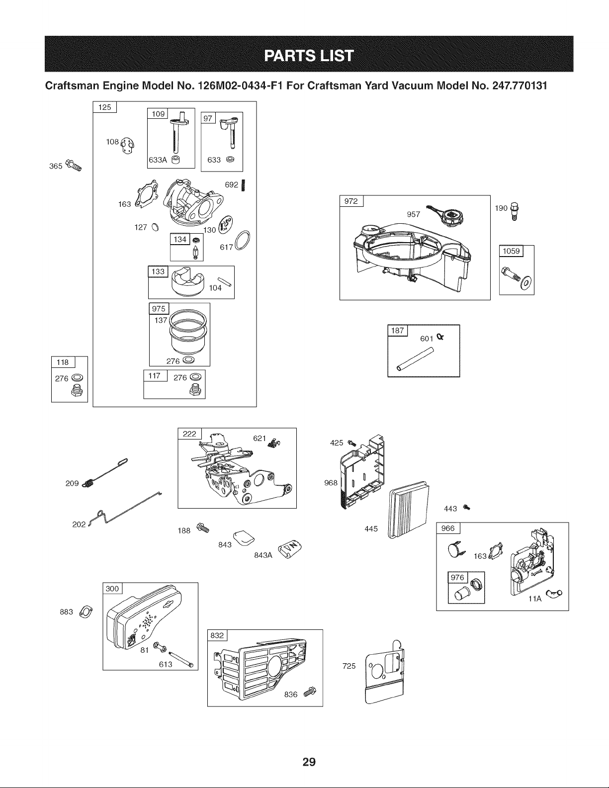
Craftsman Engine IVlodel No. 1261V102-0434-F1 For Craftsman Yard Vacuum IViodel No. 247.770131
3_s
108
@
163
@ _3 ®
692 I
130
I 276 @
276 @
4_
190
2221 621_
188
843 843A _
883
968
445
443 '_
29
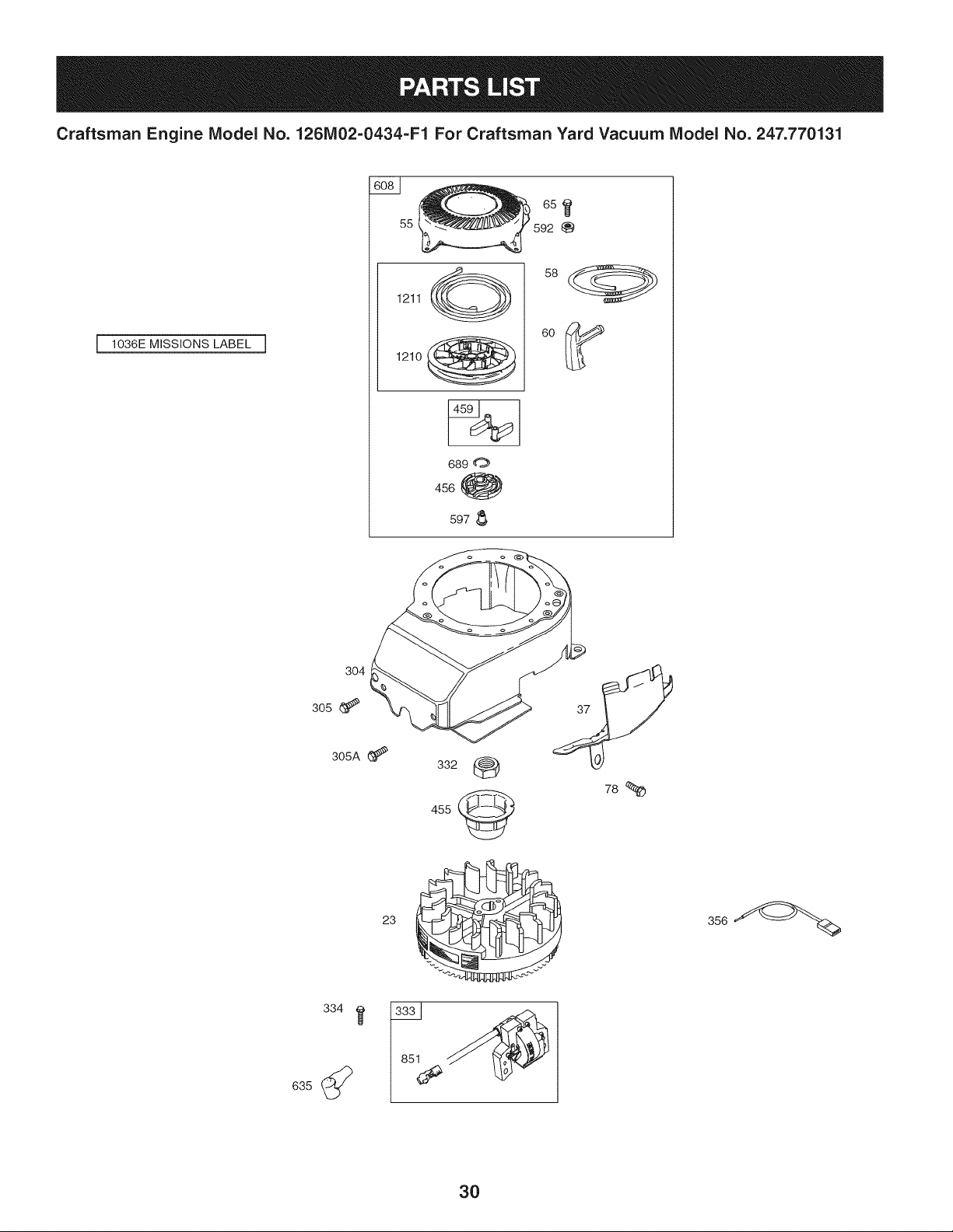
Craftsman Engine Model No. 126M02=0434=F1 For Craftsman Yard Vacuum Model No. 247.770131
1036E MISSIONS LABEL ]
6s
55
1211 (__
1210
689 0
456 _
597
304
305
305A (_
23
332
455
78
30
Craftsman Engine Model No. 126M02=0434=F1 For Craftsman Yard Vacuum Model No. 247.770131
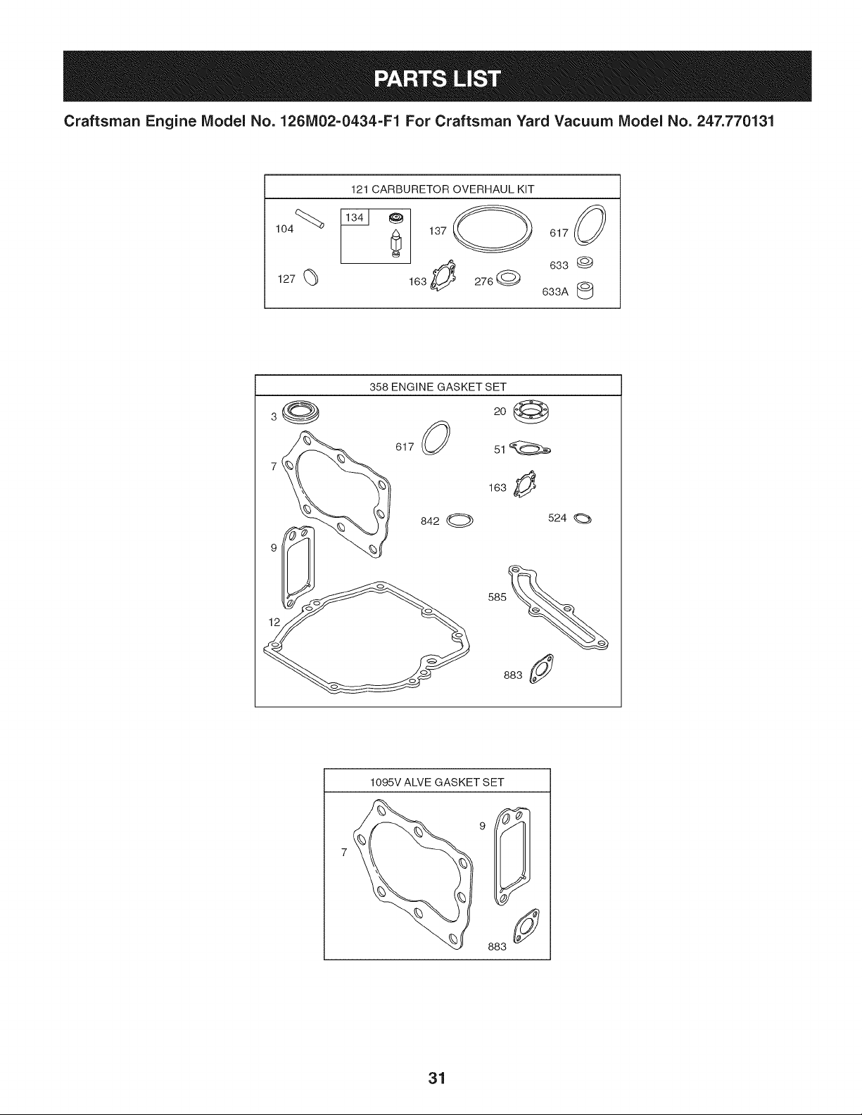
121 CARBURETOR OVERHAUL KiT
127 (_
137 O 617 (_
633 @
163 276Q
633A
358 ENGINE GASKET SET
3
617
842 O
2o1_
163 _!_
524
883
1095V ALVE GASKET SET
31
Craftsman Engine Model No. 126MO2=O434-F1 For Craftsman Yard Vacuum Model No. 247.770131
D = = O e
590401 CylinderAssembly
2. 399269 Kit-Bushing/Seal
3. 299819s Seal-Oil(MagnetoSide)
4. 493279 Sump-Engine
5. 590411 Head-Cylinder
7. 799875 Gasket-CylinderHead
8. 590395 BreatherAssembly
9. 699472 Gasket-Breather
10. 691125 Screw(BreatherAssembly)
11. 691781 Tube-Breather
11A. 691923 Tube-Breather
12. 692232 Gasket-Crankcase
13. 590422 Screw(CylinderHead)
15. 691680 Plug-OilDrain
16. 694478 Crankshaft
20. 399781s Seal-Oil(PTOSide)
22. 691092 Screw(CrankcaseCover/Sump)
23. 691987 Flywheel
24. 222698s Key-Flywheel
25. 590404 PistonAssembly(Standard)
590405 PistonAssembly(.020"Oversize)
26. 590402 RingSet (Standard)
590403 RingSet (.020"Oversize)
27. 691588 Lock-PistonPin
28. 298909 Pin-Piston
29. 797306 Rod-Connecting
32. 691664 Screw(ConnectingRod) (1/4-28x 1.09)
32A. 695759 Screw(ConnectingRod) (1/4-28x 1.52)
33. 590394 Valve-Exhaust
34. 590393 Valve-Intake
D = O
691270 Spring-Valve(Intake)
36. 691270 Spring-Valve(Exhaust)
37. 793756 Guard-Flywheel
40. 692194 Retainer-Valve
43. 691997 Slinger-Governor/Oil
45. 690548 Tappet-Valve
46. 691449 Camshaft
48. N/A Short Block- Notavailableat thisprinting
50. 794305 Manifold-Intake
51. 794306 Gasket-Intake
54. 691650 Screw(IntakeManifold)
55. 691421 Housing-RewindStarter
58. 697316 Rope-Starter
60. 281434s Grip-StarterRope
65. 690837 Screw(RewindStarter)
78. 691108 Screw(FlywheelGuard)
81. 691740 Lock-MufflerScrew
89. 692348 Plug-Oil(Cylinder)
97. 696565 Shaft-Throttle
104. 797622 Pin-FloatHinge
108. 695807 Valve-Choke
109. 498593 Shaft-Choke
117. 797574 Jet-Main(Standard)
118. 797575 Jet-Main(HighAltitude)
121. 498260 Kit-CarburetorOverhaul
125. 799869 Carburetor
127. 694468 Plug-Welch
130. 696564 Valve-Throttle
133. 398187 Float-Carburetor
134. 398188 Valve-Needle/Seat
32
Craftsman Engine
IViodel No. 126MO2=O434=F1 For Craftsman Yard Vacuum IViodel No. 247.770131
D = O
491588s Filter-AirCleanerCartridge
455. 791960 Cup-Flywheel
456. 692299 Plate-PawlFriction
459. 281505s PawI-Ratchet
505. 691251 Nut(GovernorControlLever)
523. 499621 Dipstick
524. 692296 Seal-DipstickTube
525. 495265 Tube-Dipstick
562. 691119 Bolt (GovernorControlLever)
584. 697734 Cover-BreatherPassage
585. 691879 Gasket-BreatherPassage
592. 690800 Nut(RewindStarter)
597. 691696 Screw(PawlFrictionPlate)
601. 791850 HoseClamp(Green)
608. 497680 Starter-Rewind
613. 691340 Screw(Muffler)
615. 798326 Retainer-GovernorShaft
616. 698801 Crank-Governor
617. 270344s SeaI-ORing(IntakeManifold)
621. 692310 Switch-Stop
633. 691321 Seal-Choke/ThrottleShaft(ThrottleShaft)
633A. 693867 Seal-Choke/ThrottleShaft(ChokeShaft)
635. 66538s Boot-SparkPlug
668. 493823 Spacer
684. 690345 Screw(BreatherPassageCover)
689. 691855 Spring-Friction
692. 690572 Spring-Detent
D = O
796610 Gasket-FloatBowl
163. 795629 Gasket-AirCleaner
187. 791766 Line-Fuel(Cut to RequiredLength)
188. 693399 Screw(ControlBracket)
190. 690940 Screw(FuelTank)
202. 691829 Link-MechanicalGovernor
209. 691291 Spring-Governor
222. 692150 Bracket-Control
227. 690783 ControlLever-Governor
276. 271716 SealingWasher
287. 690940 Screw(DipstickTube)
300. 692038 Muffler
304. 493294 Housing-Blower
305. 691108 Screw(BlowerHousing)(1/4-20x .62)
305A. 590763 Screw(BlowerHousing)(1/4-20x .78)
306. 690450 Shield-Cylinder
307. 690345 Screw(CylinderShield)
332. 690662 Nut(Flywheel)
333. 590454 Armature-Magneto
334. 691061 Screw(ArmatureMagneto)
337. 799876 Plug-Spark
356. 692390 Wire-Stop
358. 794307 EngineGasketSet
365. 691688 Screw(Carburetor)
404. 690272 Washer(GovernorCrank)
425. 690670 Screw(AirCleanerCover)
443. 692523 Screw(AirCleanerPrimerBase)
33
Craftsman Engine Model No. 126MO2=O434=F1 For Craftsman Yard Vacuum Model No. 247.770131
D = W O
690959 Pin-Locating
725. 590459 Shield-Heat
741. 795755 Gear-Timing
832. 590486 Guard-Muffler
836. 690664 Screw(MufflerGuard)
842. 691031 Seal-ORing(DipstickTube)
843. 691884 Sleeve-Lever
843A. 691895 Sleeve-Lever
847. 692047 Assembly-Dipstick/Tube
851. 493880s Terminal-SparkPlug
868. 590410 Seal-Valve
869. 691155 Seat-Valve(Intake)
870. 690380 Seat-Valve(Exhaust)
871. 590409 Bushing-ValveGuide
883. 793497 Gasket-Exhaust
957. 799585 Cap-FuelTank
795259
968. 692298
972. 590490
975. 796611
976. 694395
1036.
1058. 390567TRI
1059. 692311
1095. 498528
1210. 498144
1211. 498144
1329. N/A
1330. 270962
D = O O
Base-AirCleanerPrimer
Cover-AirCleaner
Tank-Fuel
Bowl-Float
Primer-Carburetor
Label-Emission(Availablefromauthorized
Briggs& Strattondealer)
Owner'sManual
Kit-Screw/Washer(FuelTank)
GasketSet-Valve
Assembly-Pulley/Spring(Pulley)
Assembly-Pulley/Spring(Spring)
ReplacementEngine(NotAvailable
at this Printing)
RepairManual
CarburetorOverhaulKit ReferenceNumber121
EngineGasketSet ReferenceNumber358
ValveGasketSet ReferenceNumber1095
34
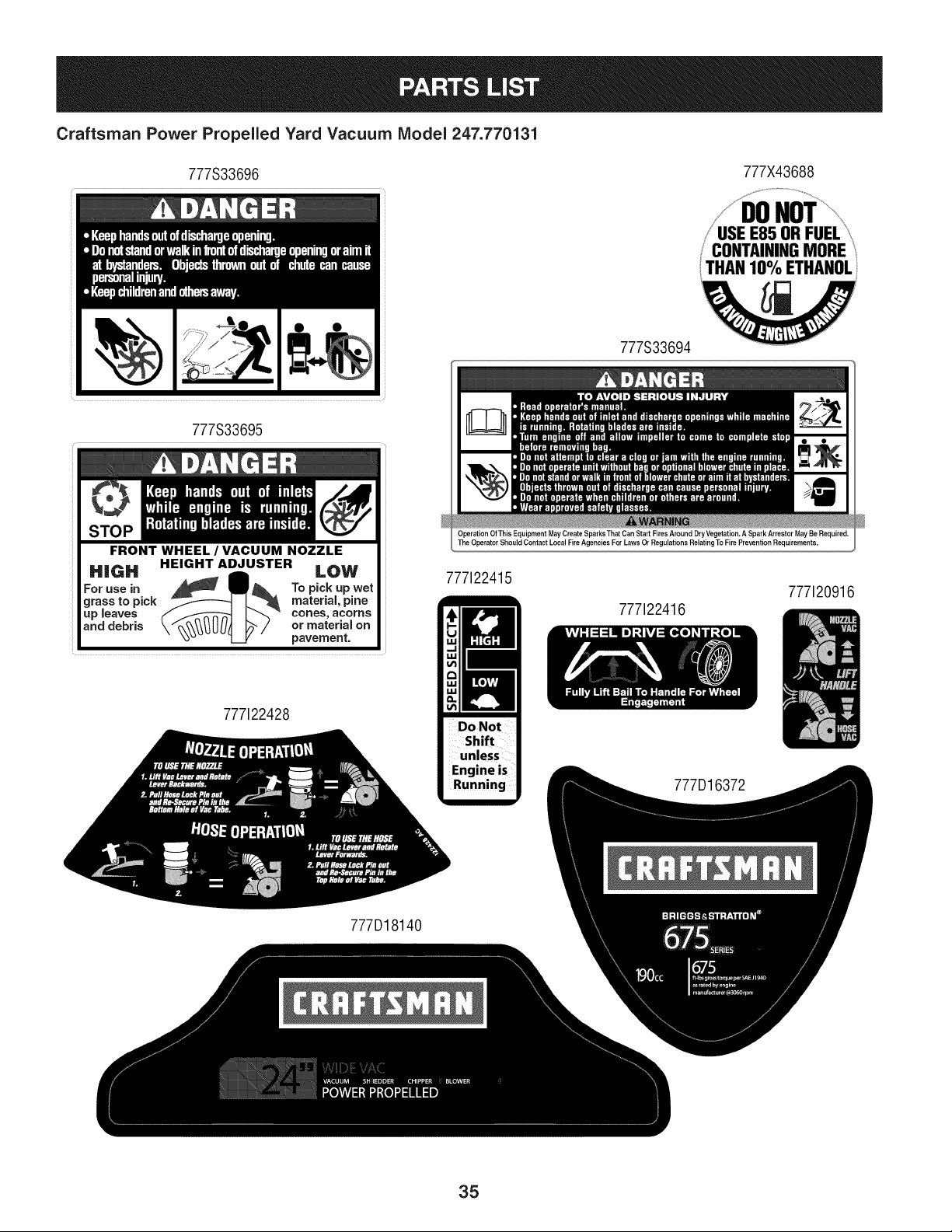
Craftsman Power Propelled Yard Vacuum IViodel 247.770131
777S33696 777X43688
ITHANIO%ETHANOL
777S33694
777S33695
FRONT WHEEL / VACUUM NOZZLE
HiGH HEIGHT ADJUSTER LOW
For use in To pick up wet
grass to pick material, pine
Lip Jeaves cones, acorns
and debris or material on
pavement.
777122428
Operation Of This Equipment May Create Sparks That Can Start Fires Around DryVegetation. A Spark Arrestor May Be Required,
The Operator Should Contact Local Fire Agencies For Laws Or Regulations Relating To Fire Prevention Requirements.
777122415
Do Not
Shift
unless
Engine is
Running
777122416
3372
777120916
777D18140
35
(Thispageapplicablein the U.S.A.and Canadaonly.)
Sears Brands Management Corporation (Sears), the California Air Resources Board (CARD)
and the United States Environmental Protection Agency (U.S. EPA)
Emission Control System Warranty Statement (Owner's Defect Warranty Rights and Obligations)
EMISSIONCONTROLWARRANTYCOVERAGEISAPPLICABLETOCERTI-
FIEDENGINESPURCHASEDIN CALIFORNIAIN 1995ANDTHEREAF-
TER,WHICHARE USEDINCALIFORNIA,ANDTOCERTIFIEDMODEL
California and United States Emission
The CaliforniaAir ResourcesBoard(CARD),U.S.EPAand Searsare pleased
to explainthe EmissionControlSystemWarrantyon your modelyear2000and
latersmalloff-roadengine(SORE).InCalifornia,newsmall off-roadengines
mustbe designed,builtand equippedto meetthe State'sstringentanti-smog
standards.Elsewherein the UnitedStates, newnon-road,spark-ignition
enginescertifiedfor modelyear 1997and latermustmeetsimilar standardsset
forth bythe U.S.EPA.Sears mustwarranttheemissioncontrolsystemon your
YEAR 1997AND LATERENGINESWHICHARE PURCHASEDAND USED
ELSEWHEREINTHE UNITEDSTATES(ANDAFTERJANUARY1,2001 IN
CANADA).
Control Defects Warranty Statement
enginefor the periodsoftime listedbelow,providedtherehas been noabuse,
neglector impropermaintenanceof your smalloff-roadengine.Youremis-
sion controlsystemincludespartssuch as thecarburetor,air cleaner,ignition
system,mufflerand catalyticconverter.Also includedmaybe connectorsand
otheremissionrelatedassemblies.Wherea warrantableconditionexists,Sears
will repairyour smalloff-roadengineat no costto you includingdiagnosis,parts
and labor.
Sears Emission Control Defects Warranty Coverage
Smalloff-roadenginesarewarrantedrelativeto emissioncontrol partsdefects
fora periodof one year,subjectto provisionsset forth below.Ifany covered
Owner's Warranty
Asthe smalloff-roadengineowner,you are responsiblefor the performanceof
therequiredmaintenancelistedin yourOperatingand MaintenanceInstruc-
tions.Searsrecommendsthatyou retain all yourreceiptscoveringmaintenance
on yoursmalloff-roadengine,butSears cannotdenywarrantysolelyfor the
lackof receiptsorfor yourfailureto ensuretheperformanceof all scheduled
maintenance.As the smalloff-roadengineowner,you shouldhoweverbe
awarethat Searsmay denyyou warrantycoverageif your smalloff-roadengine
ora part hasfailed dueto abuse,neglect,impropermaintenanceor unap-
parton yourengineis defective,the part will be repairedorreplacedbySears.
Responsibilities
provedmodifications.Youare responsiblefor presentingyour smalloff-road
engineto an AuthorizedSearsServiceDealeras soonas a problemexists.The
undisputedwarrantyrepairsshouldbe completedina reasonableamountof
time,notto exceed30 days. Ifyou haveany questionsregardingyourwarranty
rightsand responsibilities,you shouldcontacta SearsService Representative
at 1-800-469-4663.The emissionwarrantyis a defectswarranty.Defectsare
judgedon normalengineperformance.The warrantyis not relatedto an in-use
emissiontest.
Sears Emission Control Defects Warranty Provisions
ThefollowingarespecificprovisionsrelativetoyourEmissionControlDefectsWarrantyCoverage.Itisin additiontotheSearsenginewarrantyfornon-regulated
enginesfound in the Operatingand MaintenanceInstructions.
1. WarrantedParts
Coverageunderthis warrantyextendsonly to the parts listedbelow (the
emissioncontrolsystemsparts)to the extentthese partswere presenton
theenginepurchased.
a. FuelMeteringSystem
• Cold start enrichmentsystem
• Carburetorand internalparts
• FuelPump
b. Air lnduction System
• Air cleaner
• Intakemanifold
c. IgnitionSystem
• Spark plug(s)
• Magnetoignitionsystem
d. CatalystSystem
• Catalyticconverter
• Exhaustmanifold
• Air injectionsystemor pulsevalve
e. MiscellaneousItemsUsedin AboveSystems
• Vacuum,temperature,position,time sensitivevalves
andswitches
• Connectorsandassemblies
2. Lengthof Coverage
Searswarrantsto the initialownerand eachsubsequentpurchaserthat
theWarrantedPartsshallbe free fromdefects in materialsandworkman-
shipwhich causedthefailure of the WarrantedPartsfor a periodof one
yearfrom the datethe engineis deliveredto a retailpurchaser.
3. NoCharge
Repairor replacementof anyWarrantedPartwill be performedat no
chargeto the owner,includingdiagnosticlabor whichleadsto the
determinationthata WarrantedPartis defective,if the diagnosticworkis
performedat an AuthorizedSears ServiceDealer.For emissionswarranty
servicecontact yournearestAuthorizedSears ServiceDealeras listed in
the "YellowPages"under"Engines,Gasoline,""GasolineEngines,""Lawn
Mowers,"orsimilar category.
4. Claimsand CoverageExclusions
Warrantyclaimsshall be filed in accordancewiththe provisionsof the
Sears EngineWarrantyPolicy.Warrantycoverageshall be excludedfor
failuresof WarrantedPartswhichare not original Sears partsor because
of abuse, neglector impropermaintenanceas setforth inthe Sears
EngineWarrantyPolicy.Sears is notliableto coverfailuresof Warranted
Partscausedby theuse of add-on,non-original,or modifiedparts.
5. Maintenance
Any WarrantedPart whichis notscheduledfor replacementas required
maintenanceor whichis scheduledonly for regularinspectionto the effect
of "repairor replaceas necessary"shallbe warrantedas to defectsfor the
warrantyperiod.Any WarrantedPartwhich is scheduledfor replacement
as requiredmaintenanceshallbe warrantedas to defectsonly forthe
periodof time upto the firstscheduledreplacementfor that part. Any
replacementpart that is equivalentin performanceand durabilitymay
be usedin the performanceof any maintenanceor repairs.The owneris
responsibleforthe performanceof all requiredmaintenance,as definedin
the SearsOperatingand MaintenanceInstructions.
6. ConsequentialCoverage
Coveragehereundershallextend to thefailure of any engine components
caused bythe failureof any WarrantedPartstill underwarranty.
Inthe USAandCanada,a 24 hourhotline, 1-800-469-4663,has a menu of pre-recordedmessagesofferingyou enginemaintenanceinformation.
GDOC-100188Rev.B
36
Look For Relevant Emissions Durability Period and
Air index information On Your Engine Emissions Label
Engines that are certified to meet the California Air Resources Board (CARB) Tier 2 Emission Standards must
display information regarding the Emissions Durability Period and the Air Index. Sears Brands Management
Corporation makes this information available to the consumer on our emission labels.
The Emissions Durability Period describes the number of hours of actual running time for which the engine is
certified to be emissions compliant, assuming proper maintenance in accordance with the Operating & Mainte-
nance Instructions. The following categories are used:
Moderate: Engine is certified to be emission compliant for 125 hours of actual engine running time.
Intermediate: Engine is certified to be emission compliant for 250 hours of actual engine running time.
Extended: Engine is certified to be emission compliant for 500 hours of actual engine running time.
For example, a typical walk-behind lawn mower is used 20 to 25 hours per year. Therefore, the Emissions
Durability Period of an engine with an intermediate rating would equate to 10 to 12 years.
The Air index is a calculated number describing the relative level of emissions for a specific engine family. The
lower the Air Index, the cleaner the engine. This information is displayed in graphical form on the emissions label.
After July 1,2000, Look For Emissions Compliance Period
On Engine Emissions Compliance Label
After July 1, 2000 certain Sears Brands Management Corporation engines will be certified to meet the United
States Environmental Protection Agency (USEPA) Phase 2 emission standards. For Phase 2 certified engines, the
Emissions Compliance Period referred to on the Emissions Compliance label indicates the number of operating
hours for which the engine has been shown to meet Federal emission requirements.
For engines less than 225 cc displacement, Category C = 125 hours, B = 250 hours and A = 500 hours.
For engines of 225 cc or more, Category C = 250 hours, B = 500 hours and A = 1000 hours.
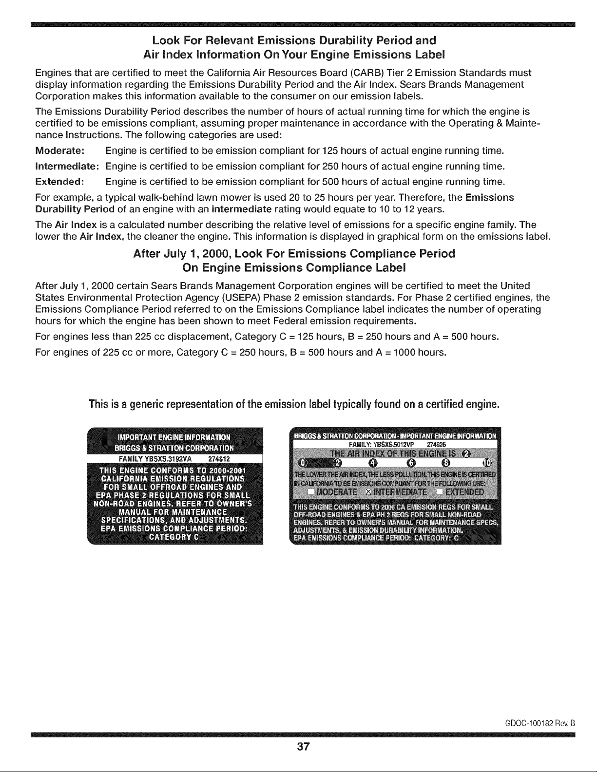
This is a generic representation of the emission label typically found on a certified engine.
FAMILYYBSXS.3192VA 274812
GDOC-100182Rev.B
37
Congratulations on making a smart purchase. Your new Craftsman® product is designed and
manufactured for years of dependable operation. But like all products, it may require repair
from time to time. That's when having a Repair Protection Agreement can save you money and
aggravation.
Here's what the Repair Protection Agreement* includes:
[] Expert service by our 10,000 professional repair specialists
[] Unlimited service and no charge for parts and labor on all covered repairs
[] Product replacement up to $1500 if your covered product can't be fixed
[] Discount of 25% from regular price of service and related installed parts not covered by the
agreement; also, 25% off regular price of preventive maintenance check
[] Fast help by phone - we call it Rapid Resolution - phone support from a Sears representative.
Think of us as a "talking owner's manual."
Once you purchase the Repair Protection Agreement, a simple phone call is all that it takes for you
to schedule service. You can call anytime day or night, or schedule a service appointment online.
The Repair Protection Agreement is a risk-free purchase. If you cancel for any reason during the
product warranty period, we will provide a full refund. Or, a prorated refund anytime after the
product warranty period expires. Purchase your Repair Protection Agreement today!
Some limitations and exclusions apply. For prices and additional information in the U.S.A.
call 1=800=827=6655.
*Coverage in Canada varies on some items. For full details call Sears Canada at 1=800=361=
6665.
Sears Installation Service
For Sears professional installation of home appliances, garage door openers, water heaters, and
other major home items, in the U.S.A. or Canada call 1=800=4=MY=HOME®.
38
Declaraci6n de garantia ....................... Pagina 39
Practicas operaci6n seguras ............... Pagina 40
Montaje ................................................ Pagina 44
Operaci6n ............................................ Pagina 48
Servicio y Mantenimiento .................... Pagina 52
Almacenamiento fuera de temporada .... Pagina 58
Soluci6n de problemas ...................... Pagina 59
Etiquetas de seguridad ....................... Pagina 7
Lista de piezas ........................................ Pagina 24
Acuerdo de Protecci6n Para
Reparaciones ....................................... Pagina 63
NOmero de servicio ..................... Cubierta posterior
ARTESANO DE DOSANOS DE GARANTJA
PORDOSANOS(S) apartirdela fechadecompra,esteproductoest&garantizadocontracualquierdefectodematerialo manode obra.Un
productodefectuosorecibir&la reparaci6no la sustituci6nsi la reparaci6nno estAdisponible.
Paraobtenerinformaci6ndetalladacoberturade lagaranfiaparaobtenerla reparaci6no sustituci6ngratuita,visiteel sitioweb: www.craftsman.com
EstagarantiacubrelosdefectosSOLOde materialesy fabricaci6n.Lagarantiano incluye:
• Elementosreutilizablesquepuedengastarseporel uso normaldentrodel periodode garantia,talescomolascuchillas,bujias,filtrode
aire,pantallade desgranadoy una bolsa.
• ProductodaSosresultantesde los intentosdelusuariodemodificaci6ndelproducto,reparaci6no causadospor accesoriosde
productos.
• Reparacionesnecesariasdebidoal accidenteo por nooperaro mantenerel productosegOnlas instruccionesprovistas.
• El mantenimientopreventivoo reparacionesnecesariasdebidoa unamezclaincorrectade combustible,combustiblecontaminadoo
pasado.
Estagaranfiaes inv&lidasi esteproductose utilizaal mismotiempola prestaci6nde servicioscomercialeso si sealquilaaotra persona.
Estagarantiale otorgaderechoslegalesespecificos,y ustedtambi_npuedetenerotrosderechosquevariandeestadoa estado.
Sears Brands Management Corporation, Hoffman Estates, IL 60179
Serie: 675
Tipode aceitedel motor: SAE30
Capacidaddeaceitedel motor: 18onzas
Capacidaddecombustible: 1.5cuartos
Separaci6nde lasbujias: .020"
NSmerode modelo ..........................................................
N_merode serie ..............................................................
Fechade compra .............................................................
Registrearriba elnOmerodel modelo,elnOmerode seriey lafecha
decompra
© Sears Brands,LLC 39
Lapresenciade este sirnboloindicaque se tratade instrucciones
irnportantesde seguridadque se deben respetarparaevitar
ponerenpeligrosu seguridadpersonaly/o materialy lade otras
personas.Lea y sigatodas lasinstruccionesdeeste manualantes
de poneren funcionarnientoestarn_.quina.Si no respetaestas
instruccionespodriaprovocarlesionespersonales.Cuandoveaeste
sirnbolo,ipresteatenci6na la advertencia!
PROPOSICION 65 DE CALIFORNIA
Elescapedel motorde este producto,algunosde suscornponentes
y algunoscornponentesdelvehiculocontieneno liberansustancias
quirnicasqueelestadode Californiaconsideraque puedenproducir
c_.ncer,defectosde nacirnientou otrosproblernasreproductivos.
Estarn_.quinarueconstruidaparaseroperadadeacuerdocon
las reglasde seguridadcontenidaseneste manual.AI igualque
concualquiertipo deequipornotorizado,un descuidoo error por
partedel operadorpuedeproducirlesionesgraves.Estarn_.quina
es capazde arnputarrnanosy piesy dearrojarobjetoscon gran
fuerza.De no respetarlas instruccionesde seguridadsiguientesse
puedenproducirlesionesgraveso la rnuerte.
Su responsabilidad--Restrinja el usode estarn_.quina
rnotorizadaa las personasque lean,cornprendany respetenlas
advertenciase instruccionesqueaparecenen estemanualy en la
rn_.quina.
iGUARI)E ESTASINSTRUCCIONES!
CAPACITACION
• Lea,entienday curnplatodaslas instruccionesincluidasen
la rnAquinayen los rnanualesantesde rnontarlay utilizarla.
Guardeestemanualen un lugarseguroparaconsultasfuturasy
regulares,asi cornoparasolicitarrepuestos.
• Leael ManualdelOperadory sigatodaslas advertenciase
instruccionesdeseguridad.El fracasode hacerasi puedecausar
la heridaseriaal operadory/o personaspresentes.ParaIlarnada
de preguntas,1-800-659-5917.
• Farniliaricesecontodoslos controlesy su operaci6nadecuada.
Sepac6rnodetenerla rn_.quinay c6rnodesengranarloscontroles
r_.pidarnente.
• No perrnitanuncaque losniffos rnenoresde 16afros utilicen
estarn_.quina.Los niffosde 16afrosy rn_.srnayoresdeben
leery cornprenderlas instruccionesde operaci6ny las reglas
de seguridadcontenidasen estemanual,y tarnbi_ndebenser
capacitadosy estarsupervisadospor uno de los padres.
• Nuncaperrnitaque los adultosoperenesta rn_.quinasin recibir
antesla instrucci6napropiada.
• Mantengaa los transeQntes,ayudantes,rnascotasy niffosal
rnenosa 75piesde la rn_.quinarnientrasest,.operando.Detenga
la rn_.quinasi alguienentraenla zona.
• Nuncaenciendaun motoren espacioscerradoso enuna zona
con pocaventilaci6n.Elescapedel motorcontienernon6xidode
carbono,un gasinodoroy letal.
• No pongalas rnanoso los piescercade las piezasrotatoriaso
en lasc_.rnarasde alirnentaci6nni en la aberturade descarga.El
contactocon el motorrotatoriopuedeproducirla arnputaci6nde
dedos,rnanoso pies.
• Nuncatratede destapar[atornade alirnentaci6no la aberturade
descarga,nitrate de sacaro vaciarla bolsade laaspiradora,ni
de revisary repararlarn_.quinarnientrasel motorest,.en rnarcha.
Apagueel motory esperehastaquetodas las piezasrn6vilesse
hayandetenidoporcornpleto.Desconecteel cablede la bujiay
p6ngalode rnaneraquehaga rnasacontrael motor.
PREPARATIVOS
• Inspeccionerninuciosarnenteel _.readondeutilizar_,el equipo.
Retiretodaslas piedras,botellas,latasu otros objetosextra_os
que puedanserlevantadoso arrojadoscausandolesiones
personaleso da_osa la rn_.quina.
• Paraprotegerselosojos utilice siernpreanteojoso antiparras
de seguridadrnientrasoperala rn_.quinao rnientrasla ajusta
o repara.Losobjetosarrojadosquerebotanpuedenlesionar
gravernentelavista.
• Utilicezapatosde trabajoresistentes,desuelafuerte,asi corno
pantalonesy carnisasajustados.Las prendassueltaso las
alhajaspuedenquedaratrapadasen las piezasrn6viles.Nunca
utilicela rn_.quinadescalzoo con sandalias.Utiliceguantesde
trabajode cuerocuandoalirnentematerialpor elcanal de la
cortadora.
• Antesde encenderla rn_.quinacontrolequetodoslos pernosy
tornillosest_nbienajustadospara cornprobarquela rn_.quinase
encuentraen condicionessegurasde operaci6n.Adern_.s,realice
una inspecci6nvisualde la rn_.quinaa intervalosfrecuentespara
controlarsi la rnisrnaest,. da_ada.
• Mantengao reernplacelas etiquetasdeseguridade instrucciones
segQnsea necesario.
Manejo segurode la gasolina
Paraevitarlesionespersonaleso da_osrnaterialesseasurnarnente
cuidadosoal rnanipularlagasolina.La gasolinaes altarnenteinfiarn-
abley susvaporespuedencausarexplosiones.Se puedelesionar
gravernentesi derrarnagasolinasobreustedo sobrela ropaya quese
puedeencender.L_.vesela piely c_.rnbiesede ropade inrnediato.
• Utilices61orecipientespara gasolinaautorizados.
4O
• NuncaIlenelos contenedoresen el interiorde un vehiculo
o carni6nocaja de carnionetacon recubrirnientospl_.sticos.
Coloquesiernprelos recipientesen el pisoy lejosdelvehiculo
antesde Ilenarlos.
Retireel equipoa gasolinadelcarni6no rernolquey II_neloen
el piso.Si estonoes posible,entoncesIlenedichoequipoenun
rernolqueconun recipienteport_.til,en vezde desdeun dispen-
sadorde gasolina.
Mantengala boquillade llenadoencontactoconel horde dela
entradadeltanquedegasolinao contenedorentodo rnornento
hastaqueest_Ileno. Noutilice undispositivopara abrir/cerrarla
boquilla.
Apaguetodoslos cigarrillos,cigarros,pipasy otras fuentesde
cornbusti6n.
Nuncacarguecombustibleen la rn_.quinaen un espaciocerrado.
Nuncasaquela tapa delgas ni agreguecombustiblernientrasel
motorest,.calienteo enrnarcha.Dejequeel motorseenfrie por
Io rnenosdosrninutosantesde volvera cargarcombustible.
Nuncarecargueel tanquede combustible.Lleneel tanqueno
rn_.sde 1/2 pulgadapordebajode la basedelcuellodelfiltro
paradejarespacioparala dilataci6ndel combustible.
• Vuelvaa colocarla tapade lagasolinay ajOstelabien.
• Lirnpielagasolinaderrarnadasobreel motory elequipo.Traslade
la rn_.quinaa otra zona. Espere5rninutosantes deencenderel
motor.
• Nuncaalrnacenela rn_.quinao el recipientede combustibleen
unespaciocerradodonde hayafuego,chispaso luz piloto(por
ejernplo,hornos,calentadoresdeagua,calefactores,secadores
de ropa,etc.)
• Parareducirel riesgodeincendiornantengalarn_.quinalirnpia
depasto,hojasy de acurnulaci6nde otros desechos.Lirnpielos
derrarnesde aceiteo combustibley saquetodos los desechos
ernbebidosconcombustible.
OPERACION
• No pongalas rnanoso los piescercade las piezas rotatoriaso
enlas c_.rnarasdealirnentaci6nni en la aberturade descarga.El
contactocon el motorrotatoriopuedeproducirla arnputaci6nde
dedos,rnanoso pies.
• Antesdeencenderlarn_.quinacornpruebeque el canaldela
cortadora,latornade alirnentaci6ny lac_.rnarade corteest_.n
vadas y sin desechos.
• Inspeccionerninuciosarnentetodoel materialquedeseatriturar
y saquelos objetosrnet_Jicos,piedras,botellas,latasu otros
objetosextra_osquepuedenocasionarlesioneso da_arla
rn_.quina.
Siel motorgolpeaunobjetoextra_oo si la rn_.quinaernpiezaa pro-
ducirun sonidopococornOnounavibraci6n,apagueel motorde
inrnediato.Dejequeel motorse detengaporcornpleto.Desconecte
el cablede labujia,p6ngalode rnaneraquehagarnasacontrael
motory sigaestospasos:
a. Inspeccionela rn_.quinaparaver si est,.da_ada.
b. Repareo reernplacelaspiezasda_adas.
c. Controlesi hay piezasflojasy ajQstelaspara asegurarquela
rn_.quinafuncionede rnaneraseguray continua.
• Noperrnitaquese acurnulematerialprocesadoen la zonade
descarga.El rnisrnopuedeobstaculizarla descargaadecuada
y provocarel retornodel materiala travesde la aberturade
alirnentaci6n.
• Nointentetriturarni picarmaterialdemayortarna_oal espe-
cificadoen la rn_.quinao en estemanual.Sepodrianproducir
lesioneso da_os.
• Nuncatratede destaparla tornade alirnentaci6no la abertura
de descargarnientrasel motorest,.en rnarcha.Apagueel motor
y esperehastaque todaslaspiezasque sernuevense hayan
detenidopor cornpleto,desconecteel cablede la bujfay p6ngalo
de rnaneraquehaga rnasacontraelmotorantes de sacarlos
escombros.
• Nuncaoperela rn_.quinasinque la bolsade la aspiradoray el
canalde descargaest_n conectadosa larn_.quinacornocorre-
sponde.Nuncavade ni carnbiela bolsade la aspiradorarnientras
el motorest,.en rnarcha.El extrernocon cierrede labolsade la
aspiradoradebequedarcerradotodoel tiernpornientrasla opera.
• Nuncaoperela rn_.quinasi el picode ingresoo la uni6nopcional
parala rnangueranoest_.nconectadosa la rn_.quinaadecu-
adarnente.Nuncaintenteconectaro carnbiarningunade estas
unionesrnientrasel motor est,.en rnarcha.
• Mantengatodoslos protectores,desviadoresy dispositivosde
seguridaden su lugaryen buenascondiciones.
• Mientrasalirnentamaterialdentrode la rn_.quinarnantengasu
rostroy su cuerpodetr_.sy haciaun costadodelcanalde la
cortadoraparaevitarlesionesporretrocesosaccidentales.
• Nuncaopereesta rn_.quinasin buenavisibilidado ilurninaci6n.
Siernpredebeestar segurode que est,.bien afirrnadoy sostenga
bienlas rnanijas.
• Noopere estarn_.quinaen superficiescon grava.
• Noopere estarn_.quinaestandobajolos efectosdel alcoholo de
drogas.
• Elsilenciadory el motorse calientany puedenproducirquerna-
duras.Nolos toque.
• Nuncalevanteo transportela rn_.quinacuandoel motorest,.
encendido.
Sise presentansituacionesque noest_.nprevistasen este
manualseacuidadosoy useel sentidocornQn.Marquepara
contactareldepartarnentodeatenci6nal clientey obtenerel
nornbredesu distribuidorrn_.scercano.
41
MANTENIMIENTO Y ALMACENAMIENTO
• Nuncarnanipulelos dispositivosde seguridadde rnanera
irnprudente.Controleperi6dicarnentequefuncionende forrna
adecuada.
• Controlefrecuenternentequetodos lospernosy tornillosest_n
bienajustadosparacornprobarquela rn_.quinase encuentraen
condicionessegurasde funcionarniento.Adern_.s,realiceuna
inspecci6nvisualde larn_.quinaparacontrolarsi larnisrnaest,.
da_aday rep_.reladeser necesario.
• Antesde lirnpiar,repararo inspeccionarla rn_.quina,detengael
motory cornpruebeque el rnisrnoy que todaslas piezasrn6viles
se hallandetenido.Desconecteel cablede labujia y p6ngalo
de rnaneraquehagarnasacontrael motorpara evitarquese
enciendade rnaneraaccidental.
• Nocarnbiela configuraci6ndel reguladordel motorni acelere
dernasiadoel rnisrno.El reguladorcontrolalavelocidadrn_.xirna
segurade operaci6ndel motor.
• Mantengao reernplacelasetiquetasde seguridade instrucciones
segQnseanecesario.
• Sigalas instruccionesde este manualparacargar,descargar,
transportary alrnacenardernaneraseguraesta rn_.quina.
• Nuncaalrnacenela rn_.quinao el recipientede combustibleenun
espaciocerradodondehayafuego,chispaso luzpilotocornopor
ejernplo,calentadoresdeagua, hornos,secadoresde ropa,etc.
• Dejequela rn_.quinase enfriepot Io rnenos5 rninutosantesde
guardarla.
• Consultesiernpreel manualdel operadorpara conocerlas
instruccionesadecuadasparael alrnacenarnientofuerade
ternporada.
• Seg_nla Cornisi6ndeSeguridadde Productosparael Consu-
rnidorde los EstadosUnidos(CPSC)y la Agenciade Proteccidn
Arnbientalde los EstadosUnidos(EPA),esteproductotieneuna
vida Otilmediade siete(7)a_os, 6 60 horasde funcionarniento.
AI finalizarla vida Otilmedia,adquierauna rn_.quinanuevao
hagainspeccionaranualrnente_sta porun distribuidorde servicio
autorizadoparacerciorarsede que todoslos sisternasrnec_.nicos
y de seguridadfuncionancorrectarnentey no tienenexcesivo
desgaste.Si noIo hace,puedenproducirseaccidentes,lesiones
o rnuerte
• Sidebe vaciarel tanquedecombustible,h_.galoal airelibre.
• Respetelas norrnasreferentesa ladisposici6ncorrectay las
reglarnentacionessobregas,combustible,etc. para protegerel
medicarnbiente.
NO MODIFIQUE EL MOTOR
Paraevitarlesionesgraveso la rnuerte,nornodifiqueel motorbajo
ningunacircunstancia.Si carnbialaconfiguracidndel reguladorel
motorpuededescontrolarsey operara velocidadesinseguras.Nunca
carnbiela configuracidndef_.bricadel reguladordel motor.
AVISO REFERIDO A EMISIONES
Losrnotoresqueest&ncertificadosy curnplencon las regulaciones
de ernisionesfederalesEPAy de CaliforniaparaSORE(Equipos
peque_ostodoterreno)est_.ncertificadosparaoperarcongasolina
cornOnsin plornoy puedenincluirlos siguientessisternasde control
de ernisiones:Modificacidnde motor(EM) y catalizadorde tresvias
(TWO)siest_.nequipadosde esa rnanera.
GUARDACHISPAS
Estarn&quinaest,. equipadacon un motorde cornbusti6ninternay
nodebeser utilizadaen o cercade unterrenoagrestecubiertopor
bosque,rnalezaso hierbaexceptosi el sisternade escapedelmotor
est,.equipadocon un arnortiguadorde chispasque curnplaconlas
leyeslocaleso estatalescorrespondientes,encaso de habedas.
Si se utilizaun arnortiguadorde chispasel operadorIo debernantener
en condicionesde usoadecuadas.Enel Estadode Californialas
rnedidasanteriorrnenternencionadassonexigidasporIcy (Arficulo
4442del Cddigode RecursosPOblicosde California).Esposible
queexistanleyessirnilaresenotros estados.Lasleyesfederalesse
aplicanen territoriosfederales.
Puedeconseguirelarnortiguadordechispasparael silenciadora
travesde su distribuidorautorizadode rnotoreso poni_ndoseen
contactoconel departarnentode servicios.
42
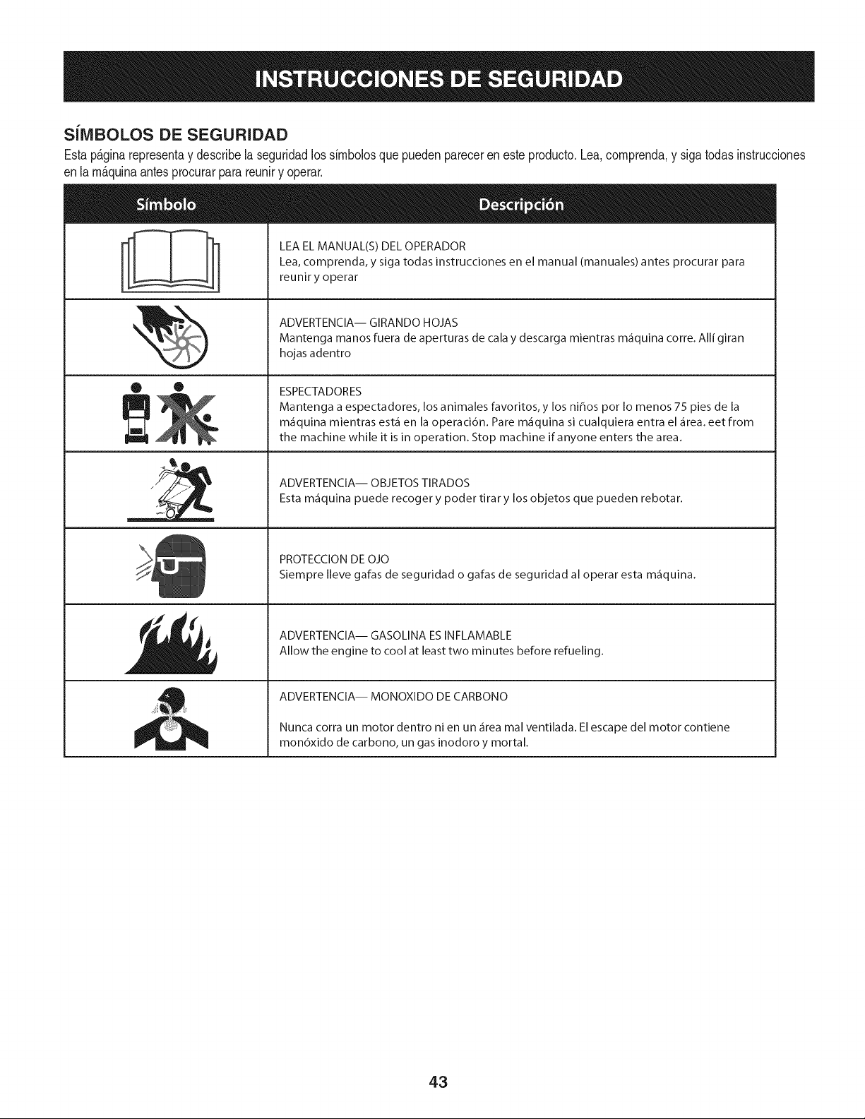
SilVIBOLOS DE SEGURIDAD
Estap&ginarepresentay describela seguridadlos simbolosque puedenpareceren este producto.Lea,comprenda,y sigatodasinstrucciones
enla m_quinaantesprocurarparareuniry operar.
O O
I-ml
llm
LEA EL MANUAL(S) DEL OPERADOR
Lea, comprenda, y siga todas instrucciones en el manual (manuales) antes procurar para
reunir y operar
ADVERTENCIA-- GIRANDO HOJAS
Mantenga manos fuera de aperturas de cala y descarga mientras m_fiquina corre. Alli giran
hojas adentro
ESPECTADORES
Mantenga a espectadores, los animales favoritos, y los ni_os pot Io menos 75 pies de la
m_iquina mientras est,1 en la operaci6n. Pare m_iquina si cualquiera entra el _irea. eet from
the machine while it is in operation. Stop machine if anyone enters the area.
ADVERTENCIA-- OBJETOS TIRADOS
Esta m_iquina puede recoger y poder tirar y los objetos que pueden rebotar.
PROTECCION DE OJO
Siempre Ileve gafas de seguridad o gafas de seguridad al operar esta m_fiquina.
ADVERTENCIA-- GASOLINA ESINFLAMABLE
Allow the engine to cool at least two minutes before refueling.
ADVERTENCIA-- MONOXIDO DE CARBONO
Nunca corra un motor dentro ni en un _irea mal ventilada. El escape del motor contiene
mon6xido de carbono, un gas inodoro y mortal.
43
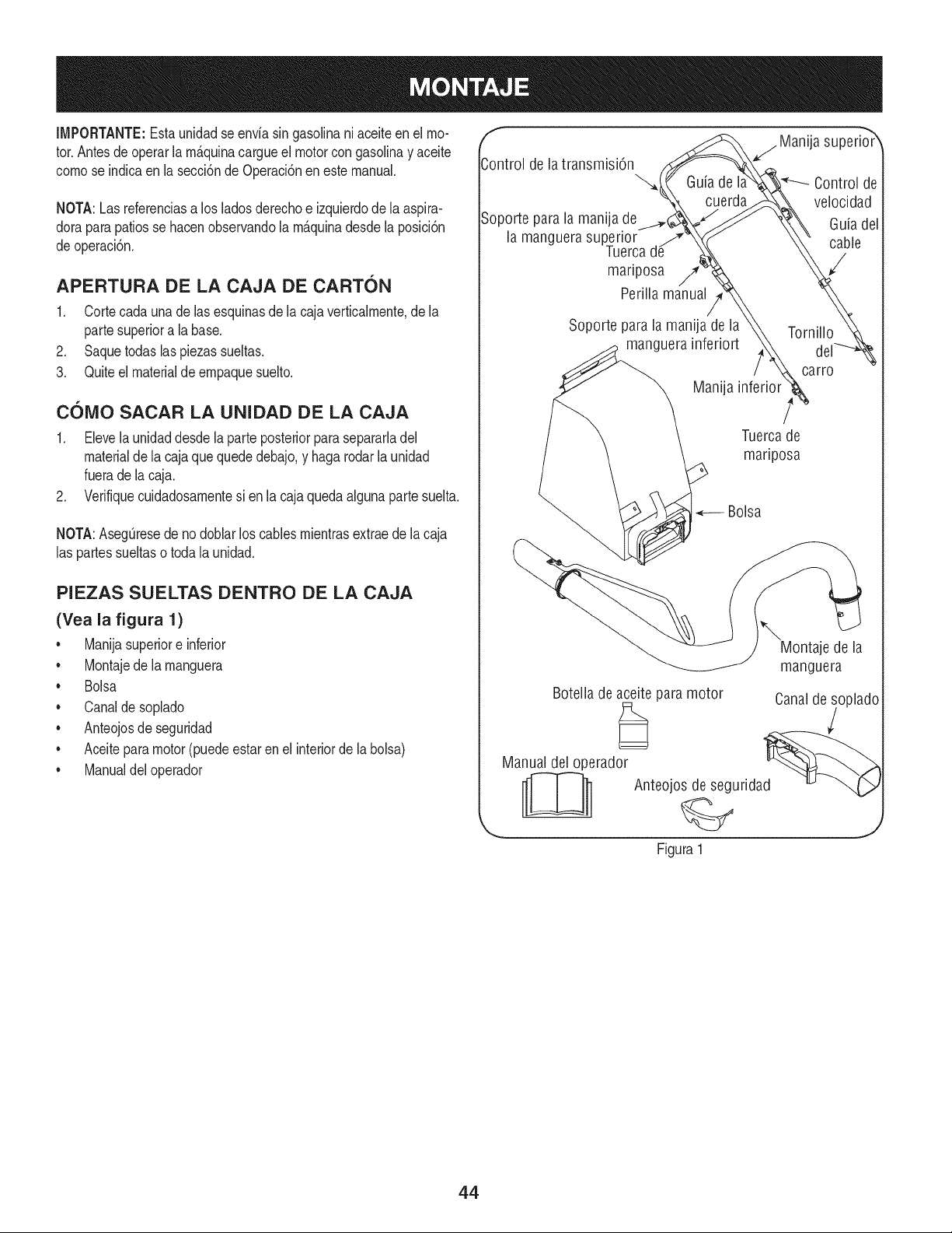
IMPORTANTE:Esta unidadse enviasin gasolinani aceiteenel mo-
tor.Antesdeoperar lam_.quinacargueel motorcongasolinay aceite
comose indicaen la secci6nde Operaci6nen este manual.
NOTA:Lasreferenciasa los ladosderechoe izquierdodela aspira-
doraparapatiosse hacenobservandola m_.quinadesdela posici6n
deoperaci6n.
APERTURA DE LA CAJA DE CARTON
1. Cortecada una de lasesquinasde la cajaverticalmente,de la
partesuperiora la base.
2. Saquetodas laspiezas sueltas.
3. Quiteel materialdeempaquesuelto.
COIVlO SACAR LA UNIDAD DE LA CAJA
1. Elevelaunidaddesdela parteposteriorparasepararladel
materialde la cajaquequededebajo,y haga rodarla unidad
fuerade la caja.
2. Verifiquecuidadosamentesi enla cajaquedaalgunapartesuelta.
NOTA:AsegQresede nodoblar loscables mientrasextraede lacaja
las partessueltaso toda la unidad.
PIEZAS SUELTAS DENTRO DE LA CAJA
(Yea la figura 1)
• Manijasuperiore inferior
• Montajede la manguera
• Bolsa
• Canaldesoplado
• Anteojosde seguridad
• Aceiteparamotor(puedeestar enel interiorde la bolsa)
• Manualdel operador
f
Control de la transmisi6n
Soporte parala manija de
la manguera superior
Tuerca
mariposa /7'
Perilla manual
j Manija superio_r
Guia de I Control de
cuerda velocidad
Guiadel
cable
Soporte para la manija de la
manguera inferiort
Manija
Tornillo
carro
Tuercade
mariposa
Bolsa
\
Montaje de la
manguera
Botella de aceite para motor Canalde soplado
Manual del operador d_ _
__ Anteojos de segurida
Figura 1
44
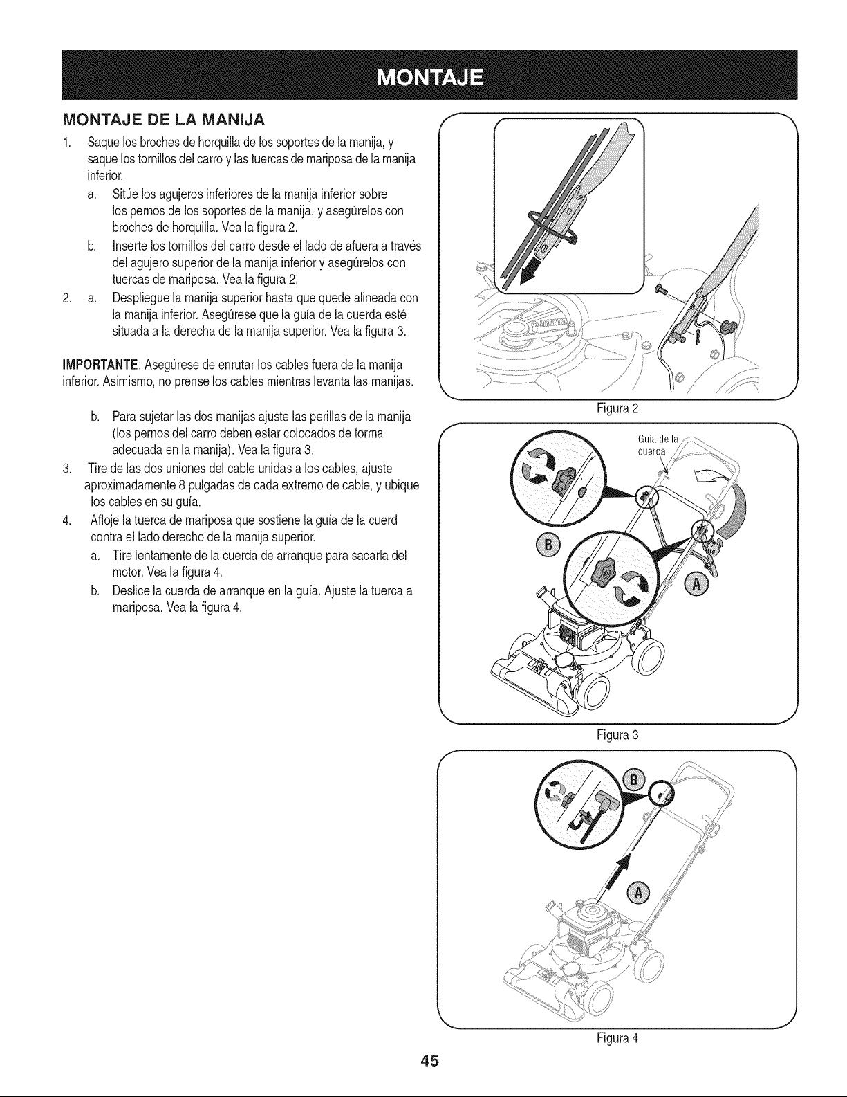
MONTAJE DE LA iVIANIJA
1. Saquelosbrochesdehorquillade lossoportesde la rnanija,y
saquelostornillosdelcarroy lastuercasdernariposadela rnanija
inferior.
a. SitOelos agujerosinferioresde la rnanijainferiorsobre
los pernosde los soportesde la rnanija,y asegOreloscon
brochesdehorquilla.Vea lafigura2.
b. Insertelostornillosdelcarrodesdeel lado de afueraa trav_s
delagujerosuperiorde la rnanijainferiory asegOreloscon
tuercasde rnariposa.Vea la figura2.
2. a. Desplieguelarnanijasuperiorhastaque quedealineadacon
la rnanijainferior.AsegQresequela guiade la cuerdaest_
situadaa la derechade la rnanijasuperior.Vea la figura3.
[MPORTANTE:AsegQresedeenrutarlos cablesfuerade larnanija
inferior.Asirnisrno,no prenselos cables rnientraslevantalas rnanijas.
.
.
b. Parasujetar[as dos rnanijasajustelas periiiasde [arnanija
(los pernosdel carrodebenestarcolocadosde forrna
adecuadaen[a rnanija).Vea[a figura3.
Tirede las dos unionesdelcableunidasa los cables,ajuste
aproxirnadarnente8 pulgadasdecadaextrernode cable,y ubique
loscablesen su guia.
Aflojela tuercade rnariposaquesostienela guia de lacuerd
contrael ladoderechode la rnanijasuperior.
a. Tirelentarnentede la cuerdade arranquepara sacarladel
motor.Veala figura4.
b. Deslicela cuerdadearranqueen la guia.Ajustela tuercaa
rnariposa.Veala figura4.
Guiade la
cuerda
45
Figura4
J
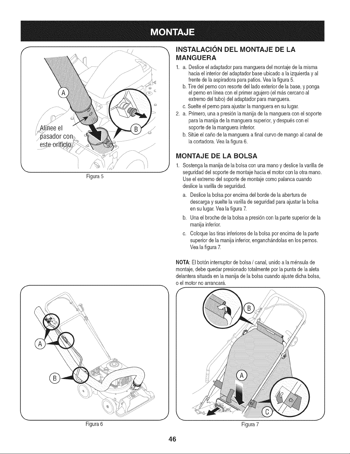
/
i' !i ee el \\\
Figura5
f
INSTALACI6N DEL iVIONTAJE DE LA
iVlANGUERA
1. a. Desliceeladaptadorpararnangueradel rnontajede la rnisrna
haciael interiordeladaptadorbaseubicadoa la izquierday al
frentedela aspiradoraparapatios.Veala figura5.
b. Tire delpernocon resortedel ladoexteriorde la base,y ponga
el pernoen Nneaconel primeragujero(elrn_.scercanoal
extrernodel tubo)deladaptadorpararnanguera.
c. Suelteel pernoparaajustarla rnangueraensu lugar.
2. a. Prirnero,unaa presi6nla rnanijade larnangueraconel soporte
parala rnanijade la rnanguerasuperior,y despu6scon el
soportede la rnanguerainferior.
b. SitQeel ca_ode la rnangueraa finalcurvode mangoal canalde
lacortadora.Vea lafigura6.
iViONTAJE DE LA BOLSA
Sostengalarnanijadela bolsacon unarnanoy deslicela variNade
seguridaddel soportede rnontajehaciaelmotorcon la otra rnano.
Useel extrernodelsoportede rnontajecornopalancacuando
deslicelavarillade seguridad.
a. Deslicela bolsapot encirnadel bordedela aberturade
descargay sueltelavariNade seguridadpara ajustarla bolsa
en su lugar.Veala figura 7.
b. Unael brochede la bolsaa presi6nconla partesuperiorde la
rnanijainferior.
c. Coloquelastirasinferioresde la bolsaporencirnade la parte
superiorde la rnanijainferior,enganch_.ndolasen lospernos.
Vealafigura 7.
NOTA:El bot6ninterruptorde bolsa/ canal,unidoa la rn6nsulade
rnontaje,debequedarpresionadototalrnentepor la puntadela aleta
delanterasituadaenla rnanijade la bolsacuandoajustedichabolsa,
o el motorno arrancar_..
Figura6
J
Figura7
46
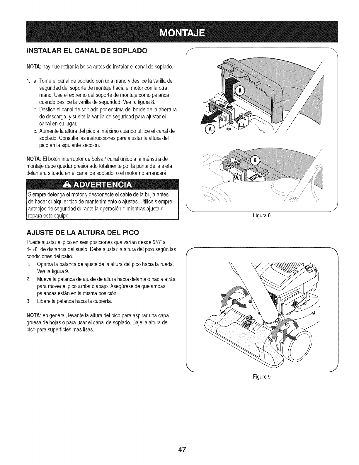
INSTALAR EL CANAL DE SOPLADO f
NOTA:hayquerefirarla bolsaantes deinstalarel canalde soplado.
1. a. Tomeelcanalde sopladocon una rnanoy deslicela varillade
seguridaddel soportede rnontajehaciael motorcon la otra
rnano.Useel extrernodelsoportede rnontajecornopalanca
cuandodeslicela varillade seguridad.Veala figura 8.
b. Desliceel canalde sopladoporencirnadel hordede la abertura
dedescarga,y sueltela varillade seguridadparaajustarel
canalen su lugar.
c. Aurnentela alturadel picoal rrn_.xirnocuandoutilice elcanalde
soplado.Consultelas instruccionesparaajustarla alturadel
picoen la siguientesecci6n.
NOTA:El bot6ninterruptorde bolsa/ canalunidoa la rn_nsulade
rnontajedebe quedar presionadototalrnentepor la puntade laaleta
delanterasituadaen el canaldesoplado,oel motor noarrancar&
Siernpredetengael motory desconecteel cable de la bujia antes
dehacercualquiertipode mantenirnientoo ajustes.Utilicesiernpre
anteojosde seguridaddurantelaoperaci6no rnientrasajustao
reparaesteequip&
/
Figura8
J
AJUSTE DE LA ALTURA DEL PICO
Puedeajustarel picoen seisposicionesquevariandesde5/8" a
4-1/8"dedistanciadel suelo.Debeajustarla alturadel pico segOnlas
condicionesdel patio.
1. Oprirnala palancade ajustede la alturadel picohaciala rueda.
Veala figura9.
2. Muevala palancade ajustede alturahaciadelanteo haciaatr_.s,
paramoverel pico arribao abajo.AsegOresede quearnbas
palancasest_.nen la misrnaposici6n.
3. Liberela palancahaciala cubierta.
NOTA:en general,levantela alturadel picoparaaspirarunacapa
gruesade hojaso para usarel canalde soplado.Baje la alturadel
pico parasuperficiesrn_.slisas.
f
Figure9
J
47
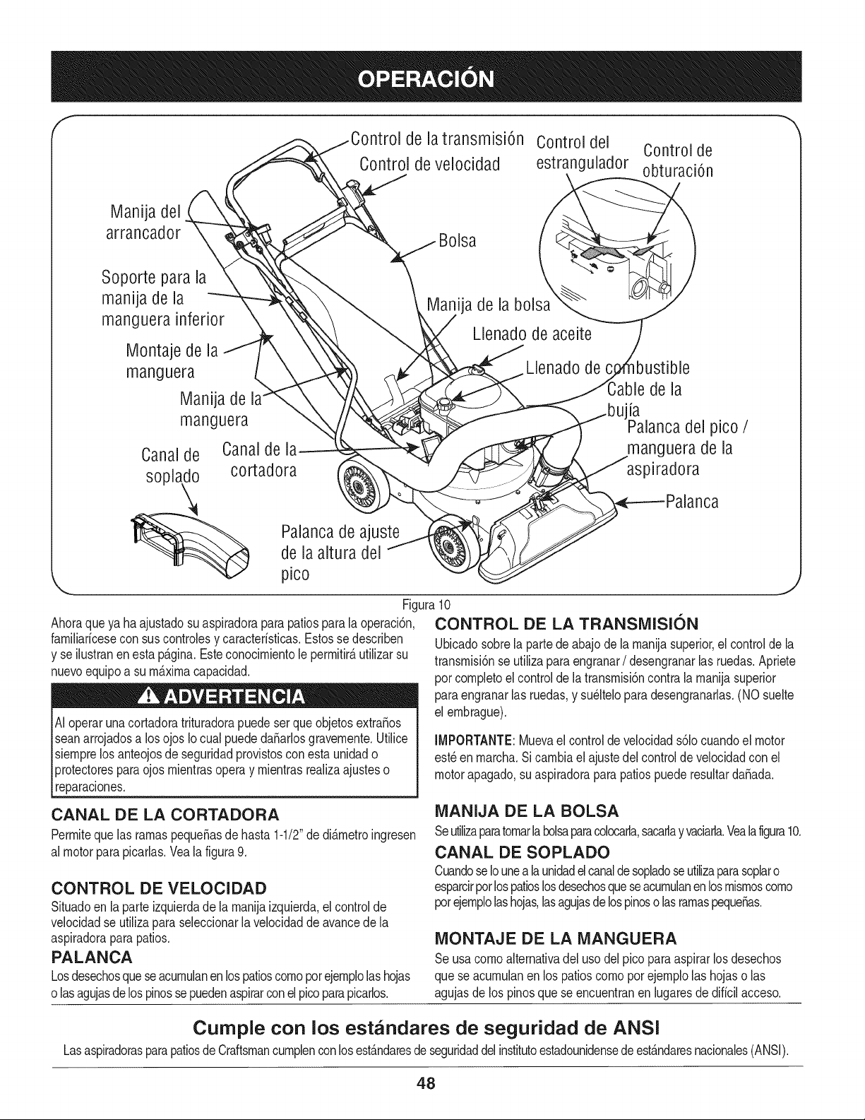
f
de la transmisi6n Control del Control de
Control de velocidad estrangulador obturaci6n
Manija del
arrancador
Soporte para la
manija de la
manguera inferior
Montaje de la
manguera
Manija de
manguera
Canalde Canaldel_
soplado cortadora
Bolsa
ija de la bolsa
Llenado de aceite
Llenado de
de la
la
del pico /
manguera de la
aspiradora
Palancade ajuste
de la altura del
pico
Ahoraqueya haajustadosu aspiradoraparapatiosparala operaci6n,
famiNarfcesecon sus controlesy caracterfsticas.Estosse describen
y se ilustranenesta p_.gina.Esteconocimientole permitir_,utilizarsu
nuevoequipoa sum_.ximacapacidad.
Ai operarunacortadoratrituradorapuedeser queobjetosextra_os
seanarrojadosa los ojos Iocual puededa_arlosgravemente.Utilice
siemprelos anteojosde seguridadprovistosconesta unidado
protectoresparaojos mientrasoperay mientrasrealizaajusteso
reparaciones.
lJ
Figura10
CONTROL DE LA TRANSMISION
Ubicadosobrela partedeabajo de la manijasuperior,elcontrolde la
transmisi6nse utilizaparaengranar/ desengranarlas ruedas.Apriete
pot completoel controlde la transmisi6ncontrala manijasuperior
paraengranarlas ruedas,y su_ltelopara desengranarlas.(NO suelte
el embrague).
IMPORTANTE: Mueva el control de velocidad s61ocuando el motor
est_ en marcha. Si cambia el ajuste dei control de velocidad con el
motor apagado, su aspiradora para patios puede resultar daSada.
CANAL DE LA CORTADORA
Permiteque las ramaspequeSasde hasta1-1/2"de di&metroingresen
al motorparapicarlas.Yeala figura9.
CONTROL DE VELOCIDAD
Situadoen laparte izquierdade la manijaizquierda,el controlde
velocidadse utilizaparaseleccionarla velocidadde avancedela
aspiradoraparapatios.
PALANCA
Losdesechosqueseacumulanen lospatioscomoporejemplolashojas
olasagujasde los pinossepuedenaspirarconelpicoparapicarlos.
MANIJA DE LA BOLSA
Seutilizaparatomarla bolsaparacolocarla,sacarlayvaciarla.Vealafigura10.
CANAL DE SOPLADO
Cuandose Iounea launidadel canalde sopladoseutilizaparasoplaro
esparcirpotlospatioslosdesechosqueseacumulanenlosmismoscomo
potejemplolashojas,lasagujasdelospinoso lasramaspeque_as.
MONTAJE DE LA MANGUERA
Se usacomo alternativadel usodelpico para aspirarlos desechos
que seacumulanen los patioscomo porejemplolas hojaso las
agujasde los pinosquese encuentranen lugaresde diffcilacceso.
Cumple con los estandares de seguridad de ANSI
LasaspiradorasparapatiosdeCraftsmancumplenconlosest&ndaresdeseguridaddelinstitutoestadounidensede est&ndaresnacionales(ANSI).
48
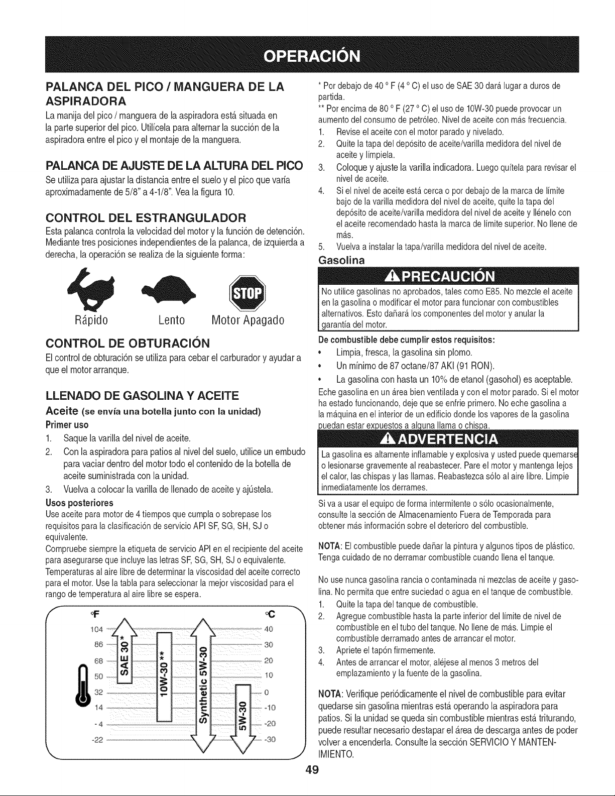
PALANCA DEL PICO / MANGUERA DE LA
ASPIRADORA
La rnanija del pico / manguera de la aspiradora est,. situada en
la parte superior del pico. Utilicela para alternar la succi6n de la
aspiradora entre el pico y el montaje de la manguera.
PALANCA DE AJUSTE DE LA ALTURA DEL PICO
Se utiliza para ajustar la distancia entre el suelo y el pico que varia
aproximadamente de 5/8" a 4-1/8". Vea la figura 10.
CONTROL DEL ESTRANGULADOR
Esta palanca controla la velocidad del motor y la funci6n de detenci6n.
Mediante tres posiciones independientes de la palanca, de izquierda a
derecha, la operaci6n se realiza de la siguiente forma:
* Pot debajo de 40 o F (4o C) el usode SAE 30 dara.lugar a duros de
partida.
** Per encima de 80 o F (27 oC) el uso de 10W-30puede provocar un
aumento dei consume de petr61eo.Nivel de aceite con ma.sfrecuencia.
1. Reviseel aceite con ei motor parade y nivelado.
2. Quite ia tapa del dep6sito de aceite/varilla medidoradel nivel de
aceite y limpiela.
3. Coloque y ajuste la varilla indicadora. Luego quitela para revisar el
nivei de aceite.
4. Si el nivel de aceite esta.cerca o pot debajo de la marca de limite
bajode la varilla medidora del nivel de aceite, quite la tapa del
dep6sito de aceite/varilia medidora dei nivei de aceite y ilenelo con
el aceite recomendado hasta la marca de limite superior.No Ilenede
ma.s.
5. Vueiva a instaiar latapa/varilla medidora del nivel de aceite.
Gasolina
R;_pido Lento Motor Apagado
CONTROL DE OBTURACION
El control de obturaci6n se utiliza para cebar el carburador y ayudar a
que el motor arranque.
LLENADO DE GASOLINA Y ACEITE
Aceite (se envia una botella junto con la unidad)
Primer uso
1. Saque la varilla del nivel de aceite.
2. Con la aspiradora para patios al nivel del suelo, utilice un embudo
para vaciar dentro del motor todo el contenido de la botella de
aceite suministrada con la unidad.
3. Vuelva a colocar la varilla de llenadode aceite y ajOstela.
Usos posteriores
Use aceite para motor de 4 tiempos que cumpla o sobrepase los
requisitos para la clasificaci6n de servicio API SE SG, SH, SJ o
equivalente.
Compruebe siempre ia etiqueta de servicio API en el recipiente del aceite
para asegurarseque incluye ias ietras SE SG, SH, SJ o equivaiente.
Temperaturasai aire libre de determinar la viscosidad dei aceite correcto
para ei motor. Use ia tabla para seleccionar la mejor viscosidad para el
rango de temperatura ai aire libre se espera.
4o
s_; so
20
50 _ _o
o ; o
s2 .
_22 30
'_., j/
No utilice gasolinas no aprobados, tabs como E85. No mezcleel aceite
en ia gasolina o modificar el motor para funcionarcon combustibles
alternatives. Esto da_ara,los componentes del motor y anular la
garanfia del motor.
De combustible debe cumplir estos requisitos:
* Limpia, fresca, la gasolina sin plomo.
. Un minimo de 87 octane/87 AKI (91 RON).
. La gasolina con hasta un 10% de etanol (gasohol) es aceptable.
Echegasolina en un a.reabien ventilada y con el motor parade. Siel motor
ha estado funcionando, deje que se enfrie primero. No eche gasolina a
la ma.quinaen ei interior de unedificio donde los vapores de la gasolina
uedan estar ex uestos a ai una llama o chis a.
La gasolina es aitamente inflamable y explosiva y usted puede quemarse
o iesionarse gravemente ai reabastecer. Pare el motor y mantenga iejos
el calor, las chispas y las llamas. Reabastezcas61oal aire libre. Limpie
inmediatamente los derrames.
Siva a usar ei equipo de forma intermitente o s61oocasionaimente,
consulte ia secci6n de Aimacenamiento Fuera de Temporada para
obtener ma.sinformaci6n sobre el deterioro del combustible.
NOTA: El combustible puede dahar la pintura y aigunos tipos de plastico.
Tenga cuidado de no derramar combustible cuando Ilenael tanque.
No use nunca gasolina rancia o contaminada ni mezclas de aceite y gaso-
lina. No permita que entre suciedad o agua en el tanque de combustible.
1. Quite ia tapa del tanque de combustible.
2. Agregue combustible hasta ia parte inferior del iimite de nivel de
combustible en ei tube del tanque. No iiene de ma.s.Limpie el
combustible derramado antes de arrancar el motor.
3. Aprieteeltap6n firmemente.
4. Antes de arrancar el motor,alejese al menos3 metros del
emplazamiento y la fuente de la gasolina.
NOTA:Verifiqueperi6dicamenteel nivelde combustibleparaevitar
quedarsesin gasolinamientrasest,.operandola aspiradorapara
patios.Si la unidad sequeda sincombustiblemientrasest,.triturando.
puederesultarnecesariodestaparel _.reade descargaantesdepoder
volvera encenderla.Consultela secci6nSERVlCIOY MANTEN-
IMIENTO.
49
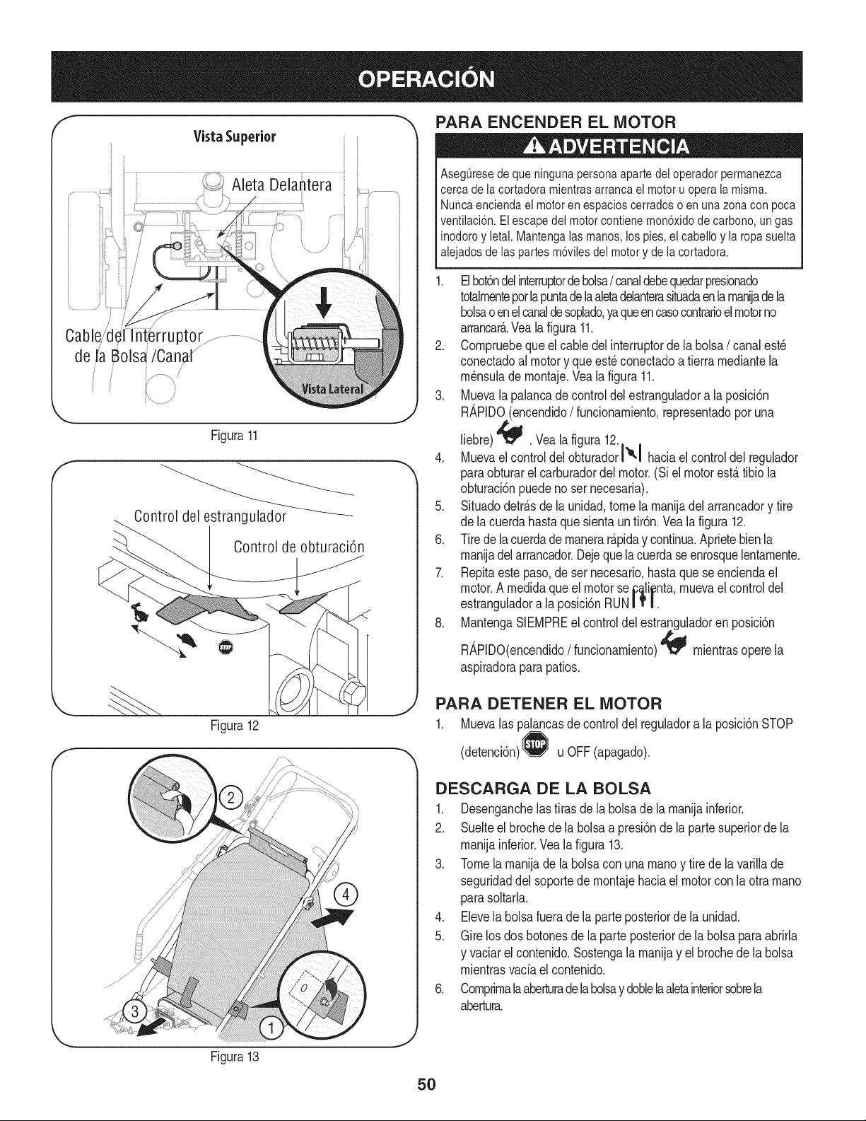
Vista Superior
Cable/d{ ptor
de JaBols_/Canal ..........
i /
Figura11
Controldel estrangulador _
Controlde obturaci6n
PARA ENCENDER EL MOTOR
AsegQresede que ninguna persona aparte dei operador permanezca
cerca de ia cortadora mientras arranca el motor u opera la misma.
Nunca encienda el motor en espacios cerrados o en una zona con poca
ventilaci6n. El escape del motor contiene mon6xido de carbono, ungas
inodoro y ietai. Mantenga ias manos, los pies, el cabello y la ropa suelta
alejados de las partes m6viles del motor y de la cortadora.
1. Elbot6ndelinterruptordebolsa/ canaldebequedarpresionado
totalmenteporlapuntadelaaletadelanterasituadaen lamaniadeia
bolsao enelcanaldesoplado,yaqueencasocontrarioel motorno
arrancar_..Vealafigura 11.
2. Compruebeque el cabledelinterruptorde ia boisa/ canalest_
conectadoal motory queest_ conectadoa tierramediantela
m_nsulade montaje.Vea la figura 11.
3. Muevala palancade controldel estranguladora la posici6n
RAPIDO(encendido/ funcionamiento,representadoporuna
liebre)'_ . Veala figura 12.
4. Muevael controldel obturadorl'°-I haciaelcontroldel regulador
paraobturarel carburadordel motor.(Si el motorest,.tibio la
obturaci6npuedenoser necesaria).
5. Situadodetr_.sde launidad,tome la manijadel arrancadory tire
de lacuerdahastaquesientaun tir6n.Veala figura 12.
6. Tirede iacuerdademanerar_.piday continua.Aprietebienla
manijadel arrancador.Dejequela cuerdaseenrosquelentamente.
7. Repitaestepaso,deser necesario,hastaque se enciendael
motor.A medidaqueel motorse_a_ii_nta,muevaelcontroldel
estranguladora la posici6nRUNIT |.
8. MantengaSIEMPREel controldel estranguladoren posici6n
RAPIDO(encendido/ funcionamiento)_ mientrasoperela
aspiradoraparapatios.
Figura12
f
PARA DETENER EL MOTOR
1. Muevalas palancasde controldel reguladora la posici6nSTOP
(detenci6n) u OFF(apagado).
DESCARGA DE LA BOLSA
1. Desenganchelastirasde la bolsadela manijainferior.
2. Suelteel brochede la bolsaa presi6nde la partesuperiorde la
manijainferior.Veala figura 13.
3. Tomela manijade la bolsaconunamanoy tire de la varillade
seguridaddel soportede montajehaciaelmotorcon la otra mano
parasoltarla.
4. Elevela bolsafuerade la parteposteriorde la unidad.
5. Gire los dos botonesde la parteposteriorde la bolsa paraabrirla
y vaciarel contenido.Sostengala manijay el brochede la bolsa
mientrasvacia el contenido.
6. Comprimalaaberturade labolsay doblelaaletainteriorsobrela
abertura.
Figura13
5O
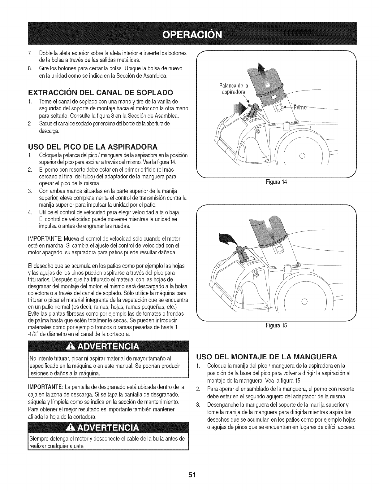
7. Doblela aletaexteriorsobrela aleta interiore insertelos botones
dela bolsaa travesde las salidasrnet_.licas.
8. Gire los botonesparacerrarla bolsa.Ubiquelabolsade nuevo
enla unidadcornose indicaen la Secci6nde Asarnblea.
EXTRACCION DEL CANAL DE SOPLADO
1. Tomeel canalde sopladocon una rnanoy tire de la varillade
seguridaddel soportede rnontajehaciael motorcon la otra rnano
parasoltado.Consultelafigura8 en la Secci6nde Asarnblea.
2. Saqueelcanaldesopladoporencirnadelhordedelaaberturade
descarga.
USO DEL PICO DE LA ASPIRADORA
1. Coloquela palancadel pico/ rnangueradela aspiradoraenla posici6n
superiordel picoparaaspirara travesdelrnisrno.Vealafigura14.
2. El pernocon resortedebeestar enel primerorificio(el rn_.s
cercanoalfinal deltubo)del adaptadorde la rnanguerapara
operarel picode la rnisrna.
3. Conarnbasrnanossituadasen la partesuperiorde la rnanija
superior,elevecornpletarnenteel controlde transrnisi6ncontrala
rnanijasuperiorparairnpulsarla unidadporel patio.
4. Utiliceelcontrol develocidadparaelegirvelocidadaltao baja.
Elcontrolde velocidadpuedernoversernientrasla unidadse
irnpulsao antes deengranarlas ruedas.
IMPORTANTE:Muevael controlde velocidads61ocuandoel motor
est_enrnarcha.Si carnbiael ajustedelcontrolde velocidadcon el
motorapagado,suaspiradoraparapatiospuede resultarda_ada.
Eldesechoquese acurnulaen los patioscornoporejernplolas hojas
y las agujasde los pinospuedenaspirarsea travesdel pico para
triturarlos.Despu_sque hatrituradoel materialcon las hojasde
desgranardel rnontajedel motor,el rnisrnoser_.descargadoa la bolsa
colectorao atrav_sdelcanalde soplado.$61outilice la rn_.quinapara
trituraro picarel materialintegrantede la vegetaci6nque se encuentra
enun pationormal(esdecir,rarnas,hojas, rarnaspeque_as,etc.)
Evitelasplantasfibrosascornoporejernplolas de tornateso frondas
depalrnahastaque est_ntotalrnentesecas.Se puedenintroducir
rnaterialescornoporejernplotroncoso rarnaspesadasde hasta 1
-1/2"de di_.rnetroenel canalde lacortadora.
Palanca de la
aspiradora
Figura14
E
_. ,J
Figura15
Nointentetriturar,picar niaspirarmaterialde mayortarnaSoal
especificadoen larn_.quinao eneste manual.Se podrianproducir
lesioneso daSosa la rn_.quina.
IMPORTANTE:La pantalladedesgranadoest,.ubicadadentrode la
cajaen la zonade descarga.Sise tapa la pantallade desgranado,
s_.quelay lirnpielacornose indicaenla secci6nde rnantenirniento.
Paraobtenerel rnejorresultadoes irnportantetarnbi_nrnantener
afiladala hojade la cortadora.
Siernpredetengael motory desconecteel cablede la bujiaantesde
realizarcualquierajuste.
USO DEL MONTAJE DE LA MANGUERA
1. Coloquelarnanijadelpico/ rnangueradela aspiradoraen la
posici6nde la basedelpico paravolvera dirigirla aspiraci6nal
rnontajede la rnanguera.Veala figura 15.
2. Paraoperarel ensarnbladode la rnanguera,el pernocon resorte
debeestaren el segundoagujerodeladaptadorde la rnisrna.
3. Desenganchela rnangueradel soportede la rnanijasuperiory
tomela rnanijade la rnangueraparadirigirla rnientrasaspiralos
desechosquese acurnulanen los patioscornoporejernplohojas
o agujasde pinosque seencuentranen lugaresde dificilacceso.
51
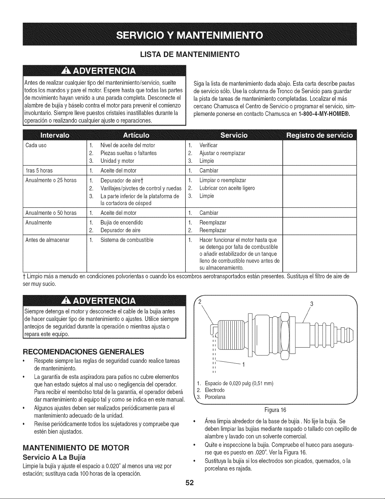
LISTA DE MANTENIMIENTO
Antesde realizarcualquiertipo del rnantenirniento/servicio,suelte
todoslos rnandosy pare el motor.Esperehasta quetodaslas partes
de rnovirnientohayanvenidoa una paradacornpleta.Desconecteel
alarnbredebujiay b_.selocontrael motorpara prevenirel cornienzo
involuntario.SiernpreIlevepuestoscristalesinastillablesdurantela
operaci6no realizandocualquierajusteo reparaciones.
Cadauso
lras 5 horas
Anuaimente o 25 horas
Sigalalista de rnantenirnientodadaabajo.Estacartadescribepautas
de servicios61o.Usela colurnnade Troncode Servicioparaguardar
la pistade tareasde rnantenirnientocornpletadas.Localizarel rn_.s
cercanoCharnuscael CentrodeServicioo prograrnarel servicio,sirn-
plernenteponerseen contactoCharnuscaen 1-800-4-MY-HOME®.
1. Nivel de aceite dei motor
2. Piezassueltaso faitantes
3. Unidad y motor
1. Aceitedei motor
1. Depuradordeairet
2. Varillajes/pivotes de control y ruedas
3. La parte inferior de ia plataforma de
ia cortadora de cesped
Aceite dei motor
Bujia de encendido
Depurador de aire
Sistema de combustible
1. Verificar
2. Ajustaroreemplazar
3. Limpie
1. Cambiar
1. Limpiaroreemplazar
2. Lubricarcon aceiteligero
3. Limpie
Anuaimenteo 50 horas 1. 1. Oambiar
Anuaimente 1. 1.
2. 2.
Antes de aimacenar 1. 1.
Reemplazar
Reemplazar
Hacer funcionar el motor hasta que
se detenga por faita de combustible
o aSadirestabilizador de untanque
Ileno de combustible nuevo antes de
su aimacenamiento.
Lirnpiorn_.sa rnenudoen condicionespolvorientaso cuandolos escornbrosaerotransportadosest_.npresentes.Sustituyaelfiltro de aire de
ser rnuysucio.
Siernpredetengael motory desconecteel cable de la bujia antes
de hacercualquiertipo demantenirnientoo ajustes.Utilicesiernpre
pnteojos de seguridaddurantela operaci6no rnientrasajustao
[reparaeste equipo.
RECOMENDACIONES GENERALES
* Respetesiernprelas reglasde seguridadcuandorealicetareas
de rnantenirniento.
, Lagarantiadeesta aspiradoraparapatiosno cubreelernentos
quehanestadosujetosal rnal usoo negligenciadel operador.
Pararecibirel reernbolsototal de la garanfia,eloperadordeber_.
darrnantenirnientoal equipotal y cornose indicaeneste manual.
, Algunosajustesdebenser realizadosperi6dicarnenteparael
mantenirnientoadecuadodela unidad.
, Reviseperi6dicarnentetodos los sujetadoresy cornpruebeque
est_nbienajustados.
MANTENIMIENTO DE MOTOR
Servicio A La Bujia
Lirnpielabujiay ajuste elespacioa 0.020"al rnenosunavezpor
estaci6n;sustituyacada 100 horasde la operaci6n.
fi 3
52
1. Espaciode 0,020 pulg(0,51mm)
2. Electrodo
3. Porcelana
Figura 16
Area lirnpia alrededor de la base de bujia. No lije la bujfa. Se
deben lirnpiar las bujfas rnediante raspado o tallado con cepillo de
alarnbre y lavado con un solvente cornercial.
Quite e inspeccione la bujia. Cornpruebe el hueco para asegura-
rse que es puesto en .020". Vet la Figura 16.
Sustituya la bujia si los electrodos son picados, quernados, o la
porcelana es rajada.
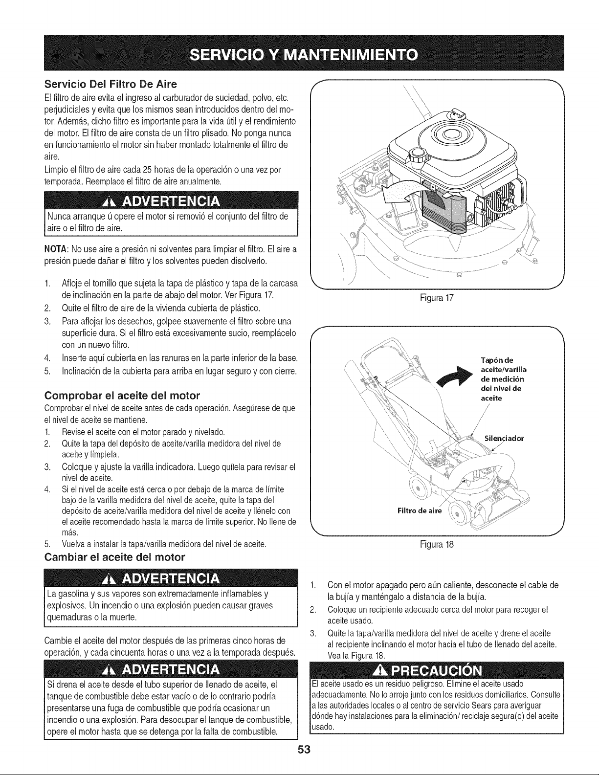
Servicio Del Filtro De Aire
Elfiltro de aire evitael ingresoal carburadorde suciedad,polvo,etc.
perjudicialesy evitaque losrnisrnosseanintroducidosdentrodelmo-
tor.AdernAs,dichofiltro es irnportantepara lavida Qtily el rendirniento
delmotor.Elfiltrode aireconstadeun filtroplisado.Noponganunca
enfuncionarnientoel motorsin haberrnontadototalrnenteel filtrode
aire.
Lirnpioelfiltrode aire cada25 horasde la operaci6no unavez per
temporada.Reemplaceel filtro deaireanualmente.
Nuncaarranqueuopereel motorsi rernovb el conjuntodelfiltrode
aireo el filtrode aire.
NOTA:Nouse aire a presi6nni solventesparaIirnpiarel filtro.Elaire a
presi6npuededaSarel filtroy los solventespuedendisolverlo.
1. Aflojeeltornilloquesujeta la tapade pl&sticoy tapade la carcasa
deinclinad6nen la partedeabajo delmotor.Ver Figura17.
2. Quiteelfiltro de aire dela viviendacubiertadepl&sfico.
3. Paraaflojarlos desechos,golpeesuavernenteel filtrosobreuna
superfMedura.Si elfiltro est&excesivarnentesudo, reernpl&celo
con unnuevofiltro.
4. Inserteaqd cubiertaen las ranurasen la parteinferiorde labase.
5. Inclinaci6nde la cubiertaparaarribaen lugarseguroy concierre.
Comprobar el aceite del motor
Comprobarel nivelde aceiteantesde cadaoperaci6n.Aseg_resede que
elniveide aceitese mantiene.
1. Reviseelaceiteconei motorparadey nivelado.
2. Quiteiatapadeldep6sitodeaceite/varillamedidoradelnivelde
aceitey limpiela.
3. Coloquey ajuste lavarillaindicadora.Luegoquitelapararevisarel
nivelde aceite.
4. Si elnivelde aceiteesta.cercao potdebajodela marcadelimite
bajodelavarillamedidoradelnivelde aceite,quitela tapadel
dep6sitodeaceite/variliamedidoradei niveldeaceitey ilenelocon
elaceiterecomendadohastalamarcade limitesuperior.NoIlenede
ma.s.
5. Vuelvaainstalarla tapa/varillamedidoradelnivelde aceite.
Cambiar el aceite del motor
Lagasolinay sus vaporessonextremadarnenteinflarnablesy
explosivos.Un incendioo una explosi6npuedencausargraves
quernaduraso la rnuerte.
Carnbieel aceitedel motordespu_sde las prirnerascincohorasde
operaci6n,y cadacincuentahoraso una veza la ternporadadespu_s.
Sidrenael aceitedesdeeltubo superiorde Ilenadode aceite,el
tanquede combustibledebeestar vado o de Io contrariopodrfa
presentarseuna fugade combustibleque podriaocasionarun
incendioo unaexplosi6n.Paradesocuparel tanquede combustible,
opereel motorhasta quese detengapor la faltadecombustible.
©
Figura17
_J
f
Tap6n de
aceite/varilla
,,
", de medici6n
"', del nivel de
aceite
/
\
\
Filtro de aire
Silenciador
J
Figura18
1. Con el motor apagado pero at]n caliente, desconecte el cable de
la bujia y rnant_ngalo a distancia de la bujfa.
2. Coloque un recipiente adecuado cerca del motor para recogerel
aceite usado.
3. Quite la tapa/varilia medidora del nivel de aceite y drene el aceite
al recipiente inclinando el motor haciael tube de Ilenado del aceite.
Vea la Figura 18.
Elaceite usadoes un residuepeligroso.Elimineel aceite usado
adecuadamente.No Ioarroje junto con los residuesdomiciliarios. Consulte
alas autoridades locales o al centrede servicio Sears para averiguar
d6nde hay instalaciones para la eliminaci6n/reciclaje segura(o)del aceite
usado.
53
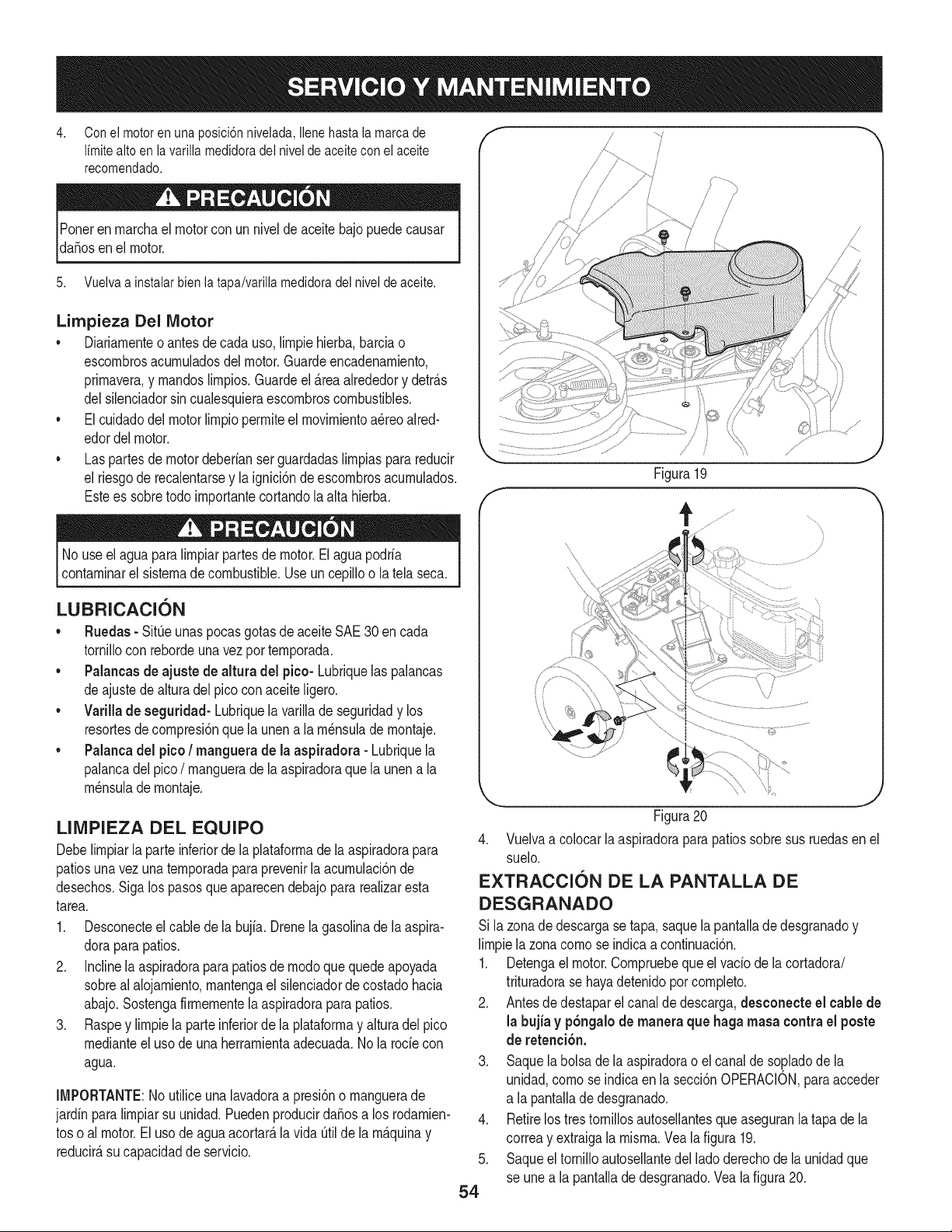
4. Con ei motor en una posici6n nivelada, ilene hasta ia marca de
Ifmitealto en lavarilla medidoradel nivel de aceite con el aceite
recomendado.
Poneren marchael motorcon un niveldeaceitebajopuede causar
da_osen el motor.
5. Vuelva a instalar bien la tapa/varilla medidora del nivel de aceite.
Limpieza Del Motor
• Diariamenteo antesdecada uso, limpiehierba,barciao
escombrosacumuladosdel motor.Guardeencadenamiento,
primavera,y mandoslimpios.Guardeel _.reaalrededory detr_.s
delsilenciadorsin cualesquieraescombroscombustibles.
• Elcuidadodelmotor limpiopermiteel movimientoa_reoaired-
edordelmotor.
• Las partesde motordeberfanserguardadaslimpiaspara reducir
el riesgode recalentarsey la ignici6nde escombrosacumulados.
Estees sobretodo importantecortandola alta hierba.
No useel aguapara Nmpiarpartesde motor.El aguapodrfa
contaminarel sistemade combustible.Useun cepiNoo latela seca.
LUBRICACI6N
• Ruedas- SitOeunaspocasgotasde aceiteSAE30 en cada
tornillocon rebordeunavez portemporada.
• Palancasde ajuste de altura del pico- Lubriquelas palancas
deajustede alturadel picoconaceiteNgero.
• Varillade seguridad- Lubriquela varillade seguridady los
resortesdecompresi6nquelaunen a la m_nsulade montaje.
• Palancadel pico/ manguera de la aspiradora - Lubriquela
palancadel pico/ manguerade laaspiradoraquela unena la
m_nsulade montaje.
LINIPIEZA DEL EQUIPO
Debelimpiarla parte inferiorde la plataformade la aspiradorapara
patiosunavezuna temporadaparaprevenirla acumulaci6nde
desechos.Sigalos pasosque aparecendebajopararealizaresta
tarea.
1. Desconecteelcable de la bujfa. Drenela gasolinade la aspira-
doraparapatios.
2. Inclinela aspiradoraparapatiosde modoquequedeapoyada
sobreal alojamiento,mantengael silenciadorde costadohacia
abajo.Sostengafirmementela aspiradoraparapatios.
3. Raspey limpiela parteinferiordela plataformay alturadel pico
medianteel usode una herramientaadecuada.Nola rode con
agua.
IMPORTANTE:Noutiliceuna lavadoraa presi6no manguerade
jardfn paralimpiarsu unidad.PuedenproducirdaSosa los rodamien-
toso al motor.El uso deagua acortar_,la vida Otilde la m_.quinay
reducir_,su capacidadde servicio.
/
J
i
l
/
/
f
Figura19
j,,J
Figura20
4. Vuelvaa colocar laaspiradoraparapatios sobresus ruedasen el
suelo.
EXTRACCION DE LA PANTALLA DE
DESGRANADO
Si la zonade descargase tapa,saquela pantalladedesgranadoy
Nmpiela zonacomose indicaacontinuaci6n.
1. Detengael motor.Compruebequeel vacfodela cortadora/
trituradorase hayadetenidopor completo.
2. Antesde destaparel canalde descarga,desconecte el cable de
la bujfa y p6ngalode maneraque haga masa contra el poste
de retenci6n.
3. Saque labolsade la aspiradorao elcanalde so.pladode la
unidad,como seindicaen la secci6nOPERACION,paraacceder
a la pantallade desgranado.
Retirelostres torniNosautosellantesqueaseguranla tapa de la
correay extraigala misma.Vea lafigura 19.
Saqueel tornilloautosellantedel ladoderechode la unidadque
se unea la pantallade desgranado.Veala figura20.
.
5.
54
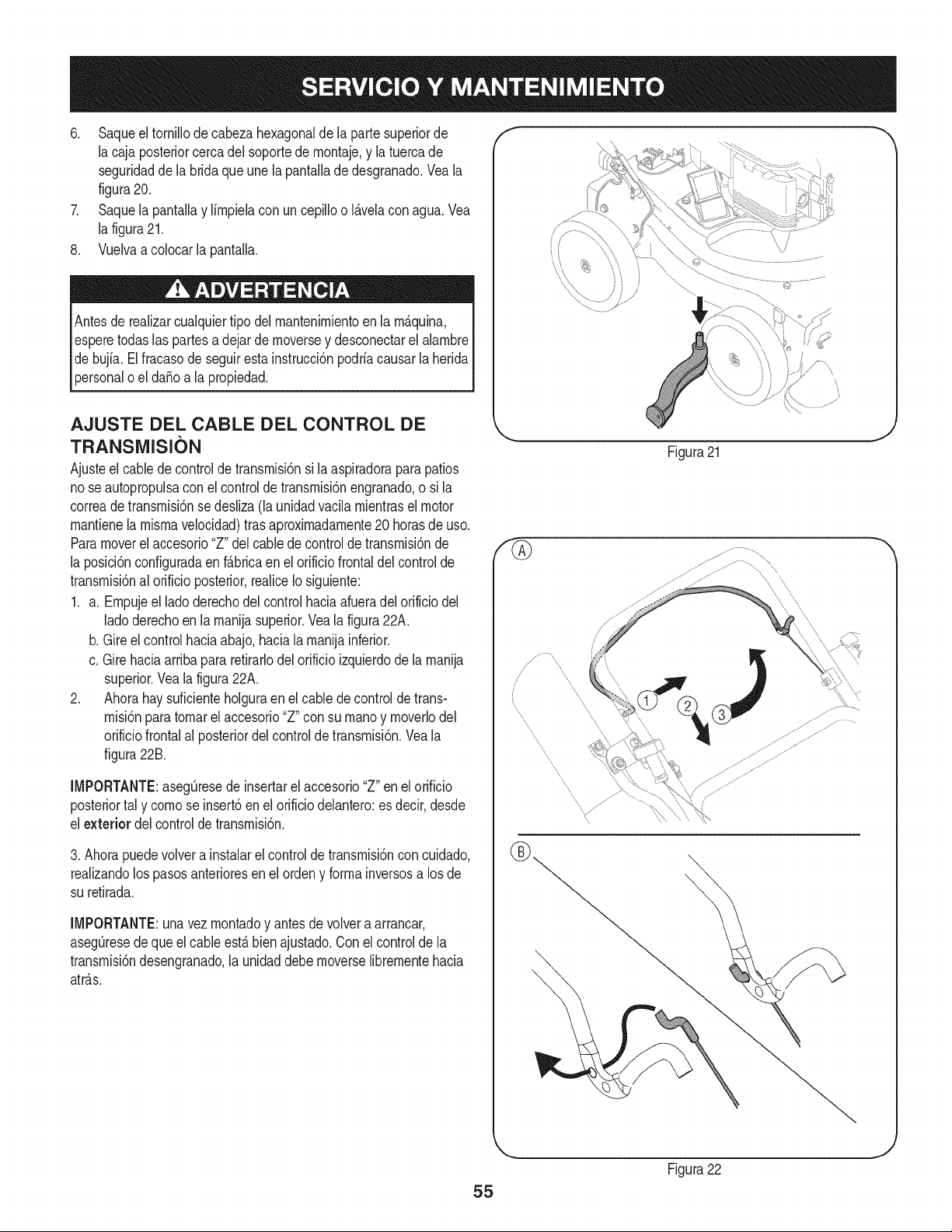
6. Saqueel tornillode cabezahexagonaldela partesuperiorde
la cajaposteriorcercadel soportede rnontaje,y la tuercade
seguridadde la bridaque unela pantallade desgranado.Veala
figura20.
7. Saquela pantallay lirnpielacon un cepilloo I_.velacon agua.Vea
la figura21.
8. Vuelvaa colocarla pantalla.
Antesde realizarcualquiertipo del rnantenirnientoen la rn_.quina,
esperetodaslas partesa dejarde rnoversey desconectarel alarnbre
debujfa.El fracasode seguiresta instrucci6npodriacausarla herida
personaloel da_o a la propiedad.
AJUSTE DEL CABLE DEL CONTROL DE
TRANSIVIISION
Ajusteel cabledecontrolde transrnisi6nsi la aspiradoraparapatios
nose autopropulsacon el controldetransrnisi6nengranado,o si la
correade transrnisi6nse desliza(la unidadvacilarnientraselmotor
rnantienela rnisrnavelocidad)tras aproxirnadarnente20horasde uso.
Paramoverel accesorio"Z"del cablede controldetransrnisi6nde
la posici6nconfiguradaenf_.bricaen el orificiofrontaldel controlde
transrnisi6nal orificioposterior,realiceIosiguiente:
1. a. Ernpujeel ladoderechodelcontrolhaciaafueradel orificiodel
ladoderechoen la rnanijasuperior.Veala figura22A.
b. Gireel control haciaabajo,haciala rnanijainferior.
c. Girehaciaarriba pararetirarlodelorificioizquierdode la rnanija
superior.Veala figura22A.
2. Ahorahay suficienteholguraenel cabledecontrolde trans-
rnisi6npara tornarel accesorio"Z" consu rnanoy rnoverlodel
orificiofrontalal 3osteriordelcontrolde transrnisi6n.Veala
figura22B.
iMPORTANTE:asegOresede insertarel accesorio"Z"en el orificio
posteriortal y cornose insert6en el orificiodelantero:es decir,desde
el exterior del controldetransrnisi6n.
3. Ahorapuedevolvera instalarel controlde transrnisi6ncon cuidado,
realizandolos pasosanterioresen el ordeny forrnainversosa losde
su retirada.
iMPORTANTE:una vezrnontadoy antesde volvera arrancar,
aseg_resedeque el cableest,.bien ajustado.Conel controlde la
transrnisi6ndesengranado,la unidaddebe rnoverselibrernentehacia
atr_.s.
f
\
J
Figura21
//
\
55
Figura22
J

AFILADO O REENIPLAZO DE LAS HOJAS DE
LA CORTADORA
NOTA:Antesde inclinarla unidad,vaciarel dep6sitode combustible
defuncionamientodelmotor hastael dep6sitoest_seco,y vaciarel
dep6sitode aceitecomose describeen Paradrenajede aceite.
1. Desconecte el cable de la bujia y p6ngalode manera que
haga masa contrael motor.
2. Retireel montajede la bolsao elcanalde soplado.
3. Ajustelos tres tornillosde cabezahexagonalquesostienenel
canalde la cortadoraa lacaja superior.Veala figura23.
4. Saquelas tapasde buje delanteras,las tuercasde seguridadde
brida,las ruedasdelanterasy lasarandelasondulatoriasquevan
unidasa losmontajesdel brazogiratorio.Vea la figura24.
5. Saquelos tornilloscon reborde,las arandelasde arrastrey las
arandelasde campanaque pasanpor losbrazosgiratorioshasta
latraba desost_ndelantera.Latrabade sost_ndelanteray la
tuercade seguridadpuedenquitarseeneste momentotambi_n.
6. Saquelos cuatrotornillosde la cajasuperiorque ajustanla
cubiertadelpico.Vea lafigura25.
f
Figura23
Trabade _ost_ndelanteray
tuercadesegu
Montaje del bra;
Arandela de campana
Arandela de arrastre
Tornillo con reborde
Arandela
ondulatoria
Tuercade
seguridad
Figura 24
Rueda
J
f
Figura25
J
56
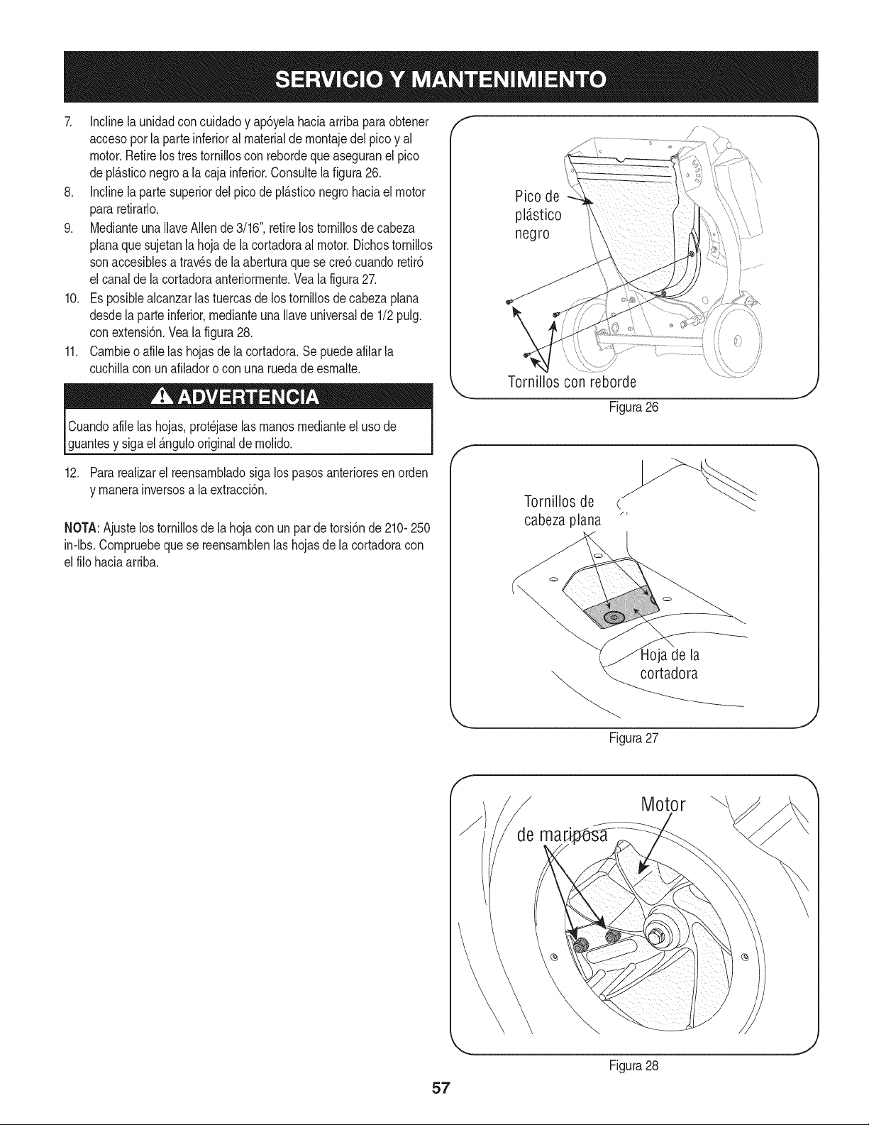
7. Inclinela unidadconcuidadoy ap6yelahaciaarriba paraobtener
accesopor laparte inferioral materialde montajedel picoy al
motor.Retirelos tres torniiloscon rebordequeaseguranel pico
depl_sticonegroa la caja inferior.Consultelafigura26.
8. Inclinela partesuperiordel picode pl_sticonegro haciaelmotor
pararetirarlo.
9. Medianteuna IlaveAllende3/16",retirelos tornillosde cabeza
planaque sujetanla hojade la cortadoraal motor.Dichostornillos
sonaccesiblesa travesde la aberturaque secre6 cuandoretir6
el canalde la cortadoraanteriormente.Veala figura27.
10. Es posiblealcanzarlas tuercasde lostornillosde cabezaplana
desdela parte inferior,medianteunaIlaveuniversalde 1/2pulg.
conextensi6n.Veala figura28.
11. Cambieo afile las hojasdela cortadora.Sepuedeafilar la
cuchillacon unafiladoro con una ruedade esmalte.
Cuandoafilelas hojas,prot_jaselasmanos medianteeluso de
guantesy sigael _ngulooriginalde molido.
12. Para realizarel reensambladosiga lospasosanterioresenorden
y manerainversosa la extracci6n.
NOTA:Ajustelostornillosde la hojacon un parde torsi6nde 210-250
in-lbs.Compruebeque se reensamblenlas hojasde lacortadoracon
el filohaciaarriba.
Pico de
pldstico
negro
Tornillos con reborde
Figura26
f
Tornillos de
cabeza plana "
a de la
cortadora
Figura27
J
Motor
Figura28
J
Nuncaalrnaceneel vacfodeyardacon elcombustibleen el tanque
dentroo en Areasrnalventiladasdondelos vaporesde combustible
puedenalcanzaruna Narnaabierta, lachispa,o el pilotocornoen un
homo,calentadorde agua,secadorde ropa,o aplicaci6nde gas.
PREPARACI6N DEL MOTOR
Yaquelos rnotoresalrnacenaronrn_.sde 30dfas:
1. Parairnpedira la gornaforrnarseenel sisternade combustible
oen partesde carburador,dirijasel motorhastaque estose
parea falta del combustibleo aSadirun aditivodegasolinaal
gasen el tanque.Si ustedusaunaditivode gas,dirige elmotor
durantevariosrninutospara poneren circulaci6nel aditivo porel
carburador-- despu_squeel motory el combustiblepuedenser
alrnacenadoshastaseisrneses.
2. Mientrasel motores todavfacaliente,carnbioel petr61eo.
3. Lirnpieel motorde escornbrossuperficiales.
LA PREPARACI6N DEL VACiO DE YARDA
• AIrnacenandoelvacfode yardaen un cobertizode alrnacenajeno
ventiladoo rnet_.lico,el cuidadodeberfasettornadoa inoxidable
las superficiesnopintadas.Usandoun petr61eoligeroo silicona,
cubrael equipo,sobretodocualquierprirnavera,portes,y cables.
• Limpiey iubriquela cortadoracomese describeenlasinstrucciones
delubricaci6n.
• Noutiliceunalavadoraa presi6nniunarnangueradejardfnpara
limpiarsu unidad.
• Almacenela unidadenunazonalimpiay seca.Nolaalmacene
cercade materialescorrosivescomeperejemplofertilizantes.
58
hayanvenidoa una paradacompleta.Desconecteel alambrede bujfay b_.selocontrael motorparaprevenirel comienzoinvolun-
SiempreIlevepuestoscristabs inastillablesdurantela operaci6no realizandocualquierajusteo reparaciones.
Esta secci6nsedirigea cuestionesde serviciomenores. Localizarel m_s cercanoChamuscael Centrode Servicio o prograrnarel
servicio,simplementeponerseen contactoChamuscaen 1-800-4-MY-HOME®.
Elmotornoarranca
Elmotorfuncionade manera
err_.tica
1. La palancadel reguladornoest,. en la
posici6nde arranquecorrecta
2. La palancade obturaci6nnoest,. en la
posici6nCHOKE(encendido)
3. Se ha desconectadoel cablede la bujia
4. La bujianofuncionacorrectamente
5. El tanquede combustibleest,.vado o el
combustiblees viejo
6. No se puedetirarde lacuerdade retroceso
7. El interruptordeseguridadno est,.
presionado
8. El cabledel interruptorde seguridadnoest,.
conectadoal motoro no est,. conectadoa
tierracomocorresponde
1. La unidadest,.funcionandoenla posici6n
CHOKE(obturaci6n)
2. El cablede la bujfaest,.fiojo
3. EIcombustibleesviejo
4. Aguao suciedaden el sistemadel combus-
tible
5. El filtrodeaire est,.sucio
6. RPMdel motorbajas
7. Es necesarioajustarelcarburador
1. Muevala palancadel reguladora la posici6n
R_.PIDO.
2. Pongaelinterruptoren laposici6nCHOKE(obtura-
ci6n).
3. Conecteelcable a la bujfa.
4. Limpie.ajusteladistanciadisruptivao cambie.
5. Lieneel tanquecon gasolinalimpiay fresca.
6. Hayunaobstrucci6nen el motor.Desconecteel
cable de labujiay retireel objetoatascado.
7. El interruptorde seguridaddebeser presionadopor
laaletadelanterade la manijade la bolsacuandose
asegurala bolsa.
8. Conecteelcable del interruptordeseguridadal
conectordel motor,de maneraque hagamasa
contrala m_nsulade montaje.
1. Cambiela palancade obturaci6na la posici6nRUN
(apagado).
2. Conectey ajusteel cablede la bujia.
3. Lieneel tanquecon gasolinalimpiay fresca.
4. Vacieel tanquedelcombustible.Vuelvaa Ilenarlo
con combustiblelimpio.
5. Limpieo cambieel filtrode aire.
6. Siempreaccioneelmotorcon el estranguladoral
m_.ximo.
7. Contactecon su centrode partesy reparaciones
Sears.
LNECESITA MAS AYUDA?
E:_cor_tr#r5 b I_e pue t# y m_ en managemylife.com - isin cargo!
En linea podr_ encontrar este manual y los manuales de todos los otros productos que posea,
Sus preguntas ser_n respondidas pot nuestro equipo de especialistas,
Obtenga un plan de rnantenimiento personalizado para su hogar,
Encuentre informaciOn y herramientas que Io ayudar_n con los proyectos de su hogar,
managemylife
59
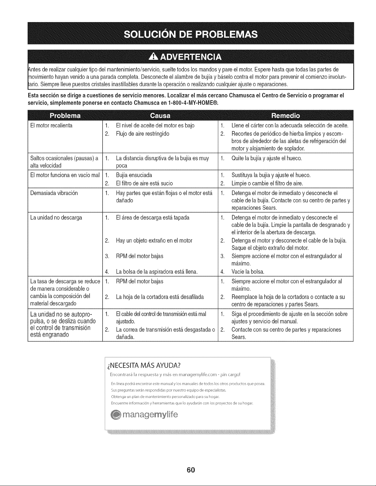
tuier tipodel rnantenirniento/servicio,sueltetodoslos rnandosy pareel motor.Esperehastaque todaslaspartesde
yan venidoa unaparadacornpleta.Desconecteel alarnbrede bujfay b_.selocontrael motorparaprevenirel cornienzoinvolun-
SiernpreIlevepuestoscristabs inastillablesdurantelaoperaci6no realizandocualquierajusteo reparaciones.
Esta secci6nsedirigea cuestionesde serviciornenores. Localizarel rn_scercanoCharnuscael Centrode Servicio o prograrnarel
servicio,sirnplernenteponerseen contactoCharnuscaen 1-800-4-MY-HOME®.
El motorrecalienta
1. El nivelde aceitedel motores bajo
2. Flujodeairerestringido
Saltosocasionabs(pausas)a 1. Ladistanciadisruptivade labujiaes rnuy
alta velocidad poca
El motorfuncionaen vado rnal 1. Bujiaensuciada 1.
2. El filtrode aireest,. sucio 2.
Dernasiadavibraci6n 1. Haypartesqueest_.nfiojas o el motorest,. 1.
da_ado
La unidadnodescarga 1. El_.readedescargaest,.tapada 1.
Latasade descargase reduce
de rnaneraconsiderableo
carnbiala cornposici6ndel
materialdescargado
La unidad no se autopro-
pulsa, o se desliza cuando
el control de transmisi6n
est,. engranado
2. Hay unobjetoextra_oen el motor
3. RPMdel motorbajas
4. La bolsade la aspiradoraest,.Ibna.
1. RPMdel motorbajas
2. La hojade lacortadoraest,. desafilada
1. Elcabledelcontroldetransrnisbnest,.rnal
ajustado.
2. La correade transrnisi6nest,.desgastadao
da_ada.
1. Lleneel c_.rtercon la adecuadaselecci6nde aceite.
2. Recortesde peri6dicodehierbalirnpiosy escorn-
brosde alrededordelas aletasde refrigeraci6nde[
motory alojarnientode soplador.
1. Quitela bujiay ajusteel hueco.
.
3.
4.
Sustituyala bujfay ajusteel hueco.
Lirnpieo carnbiee[ fiitro deaire.
Detengael motorde inrnediatoy desconecteel
cablede la bujfa.Contacteconsu centrode partesy
reparacionesSears.
Detengael motorde inrnediatoy desconecteel
cablede la bujfa.Lirnpiela pantalladedesgranadoy
elinteriordela aberturade descarga.
Detengael motory desconecteel cablede la bujia.
Saqueelobjetoextra_odel motor.
Siernpreaccioneel motorconel estranguladora[
rn_.xirno.
Vade la bolsa.
1. Siernpreaccioneel motorconel estranguladora[
rn_.xirno.
2. Reernplacela hojade la cortadorao contactea su
centrode reparacionesy partesSears.
1. Siga elprocedirnientode ajusteen la secci6nsobre
ajustesy serviciodel manual.
2. Contactecon sucentrode partesy reparaciones
Sears.
_NECESITA MAS AYUDA?
[{r_cor_tr#r5 b I_e pue b_y m_ en managemylife.com - isin cargo!
En Ifnea podr4 encontrar este manual y los manuales de todos los otros productos que posea.
Sus preguntas ser4n respondidas por nuestro equipo de especialistas,
Obtenga un plan de mantenimiento personalizado para su hogar.
Encuentre informaci6n y herramientas que Io ayudar4n con los proyectos de su hogar.
manage, mylife
6O
(Esta p_.ginase aplica s61oen EE.UU. y Canada.).
Sears Brands Management Corporation, el Consejo de Recursos Ambientales de California (CARB)
y la Agencia de Protecci6n Ambiental de los Estados Unidos (EPA)
Declaraci6n de garantia del sistema de control de emisiones (derechos y obligaciones de la garanfia de defectos del propi=
etario)
LA COBERTURADE LA GARANTJADE CONTROLDEEMISIONESES Y PARALOSMODELOSCERTIFICADOSDELANO 1997YPOSTERIORES,
APLIOABLEA LOS MOTORESCERTIFICADOSCOMPRADOSEN CALIFOR- QUESE COMPRENY UTILICENENCUALQUIERPARTEDE LOSESTADOS
NIA EN 1995Y POSTERIORMENTE,QUESE UTILIZANENCALIFORNIA, UNIDOS(Y A PARTIRDEL 1 DE ENERODE 2001 EN CANADA).
Declaraci6n de garanfia sobre defectos en el control de emisiones para California y los Estados Unidos
ElConsejode RecursosAmbientalesde California(CARB),la EPA(Agencia
de Protecci6nAmbientalde los EE.UU.)y Searstienenel gusto de explicarla
garantiadel sistemade control de emisionespara motoresdela_o 2000y para
elfuturo con relaci6na motorespeque_ostodo terreno(SORE).En California,
los nuevosmotorespeque_ostodo terrenodebenestar dise_ados,construidos
y equipadosparacumplircon las rigurosasnormasanti-smogdelestado.En
el restode los EstadosUnidos,losmotoresnuevostodoterrenode encendido
porchispa certificadosparael a_o 1997debencumplirest_ndaressimilares
establecidospot la EPA.Sears debegarantizarel sistemade control de emis-
ionesde su motorparalosperiodosde tiempo enumeradosa continuaci6n,
siemprequeno hayaabuso,negligenciao mantenimientoindebidode su
motortodoterrenopeque_o.Su sistemade controldeemisionespuedeincluir
piezastalescomoel carburador,el filtrode aire, elsistemade encendido,el
silenciadoryel conversorcatalitico.Tambienpuedeincluirconectoresy otras
unidadesrelacionadascon lasemisiones.Dondeexistaunacondici6ncubierta
por la garantia,Searsreparar_su peque6omotortodo terrenosin costoalguno
incluyendodiagn6stico,piezasy manodeobra
Cobertura de la garantJa Sears para defectos en el control de emJsiones
Los motorestodo terrenopeque6osest_ngarantizadosen Io relativoalcontrol alas disposicionesque se indiquena continuaci6n.Si una partede su motor
de emisionesparadefectosen piezasduranteun periodode dos a_os,sujeto cubiertapot lagaranfiaes defectuosa,Sears reparar_o sustituir_dichaparte.
Responsabilidades del propietario en relacibn con la garantia
Comopropietariodel motortodo terrenopeque_o,Ud.es responsablede la
realizaci6ndel mantenimientorequeridoquese incluyeen las instrucciones
de operaci6ny mantenimiento.Searsrecomiendaquese conserventodoslos
recibosrelativosal mantenimientode su motortodoterrenopeque_o,pero
no pude denegarla garantiasimplementepor la faltade los mismos,o por su
incumplimientodel mantenimientoprogramatic.Comopropietariodel motor
peque_otodoterrenodebe saberque, sin embargo,Sears lepuedenegar
lacoberturade lagarantiasi su motortodoterrenopeque6oo una piezadel
mismohanfalladodebidoa abuso,negligencia,mantenimientoindebidoo
a modificacionesno aprobadas.Ud.es responsablede presentarsu motor
todoterrenopeque6oa un distribuidorde serviciosSearsautorizadotan pronto
comoaparezcaun problema.Las reparacionesde la garantiasinconfiicto
debencompletarseen un plazodetiempo razonable,no superiora 30 dias.Si
tienealguna preguntarespectoa sus derechosy responsabilidadesreferen-
tes a la garantia,debe contactarcon un representantede serviciosSearsal
1--800--469--4663.La garantiade emisioneses unagarantiapor defectos.Los
defectosse juzgande acuerdocon elfuncionamientonormalde unmotor.La
garantiano est_relacionadacon unapruebade emisionesen uso.
Disposiciones de la garantJa Sears para defectos en el control de emJsiones
Las siguientesson disposicionesespecificasrelacionadascon la coberturade lagarantia paradefectosen el controlde emisiones.Esun a_adidoa la garantiade
motorSearspara motoresno reguladosque seencuentraen lasinstruccionesde funcionamientoy mantenimiento.
1. Piezascon garantia
La coberturade esta garantiase extiendeL]nicamentealas piezas
queaparecena continuaci6n(las partesde lossistemasde control de
emisiones),siempreque dichaspiezasestuvieranya en el motoren el
momentode su compra.
a. Sistemade medici6nde combustible
• Sistema de enriquecimientopara arranqueen frio
• Carburadory partesinternas
• Bombade combustible
b. Sistemade inducci6nde aire
• Filtrode aire
• Colector de admisi6n
c. Sistemadeencendido
• Bujia(s)de encendido
• Sistema de encendidomagneto
d. Sistemadelcatalizador
• Convertidorcatalitico
• Colector de escape
• Sistema de inyecci6nde aireo v_lvulade impulsos
e. Elementosvariadosusadosen lossistemasanteriores
• Wlvulas de vacio,sensiblesa temperatura,posici6ny tiempo
e interruptores
• Conectoresy montajes
2. AIcancede la cobertura
Searsgarantizaal poseedorinicialy a los compradoressubsiguientes
quelas piezascon garantiano tendr_ndefectosen materialesni mano
de obra que provoquenla falla de las mismasduranteun periodode
dos aSosa partirde la fechaen queel motorse entregaa un comprador
particular.
3. Sin cargo
La reparaci6no reemplazode cualquierpartecon garantia se realizar_
sin cargo alguno parael poseedor,incluyendotareasde diagn6sticoque
permitandeterminarsi una partecon garantiaes defectuosa,siempreque
dichodiagn6sticose realiceen un distribuidorde serviciosSearsautoriza-
do. Parael serviciode lagarantia de emisiones,contacteal distribuidorde
serviciosSearsautorizadom_s cercanoincluidoen las"P_ginasamarillas"
en lascategorias"Motores,gasolina","Motoresde gasolina","Podadoras
de cesped",o similares.
4. Reclamacionesy exclusionesa la cobertura
Las reclamacionesde lagarantia debenenviarsedeacuerdocon las
disposicionesde la politicade garantia para motoresSears. La cobertura
de lagarantia excluir_defectosen piezascon garantia queno scan partes
originalesSears,o abuso,negligenciao mantenimientoincorrecto,tal y
como se estableceen lapolitica de garantia para motoresSears.Sears no
es responsablede lasfallas en piezas con garantia provocadaspor el uso
de partesa6adidas,que no scan originales o quese hayan modificado.
5. Mantenimiento
Cualquierpartecon garantiaque no esteprogramadaparaserreem-
plazadacomomantenimientorequerido,o que s61odebainspeccionarse
regularmentealefecto de "inspeccioneo reemplacesegL]nsea necesario",
estar_garantizadacontradefectosduranteel periodode la garantia.Todas
las piezasgarantizadasqueesten programadaspara su reemplazopara
cumplir con los requisitosde mantenimientoestar_ngarantizadass61o
por el periodoanterioral primerreemplazoprogramaticparadicha pieza.
Cualquierpiezade recambioquesea equivalenteen funcionamientoy
durabilidadpuedeusarse para realizar mantenimientoo reparaciones.El
propietarioes responsablede realizartodoel mantenimientorequerido,tal
y comose define en las instruccionesde funcionamientoy mantenimiento
Sears
6. Coberturaindirecta
Porla presente,la coberturase extiendea la falla de cualquiercomponente
de motorprovocadapot lafalla de unapieza con garantiaque estetodavia
en periodode garantia.
En los EstadosUnidosy Canad_hayunalinea de atenci6nde 24 horas,1-800-469--4GG3,quecuentacon un menL]con mensajespre-grabadosque contienen
informaci6npara el mantenimientodemotores.
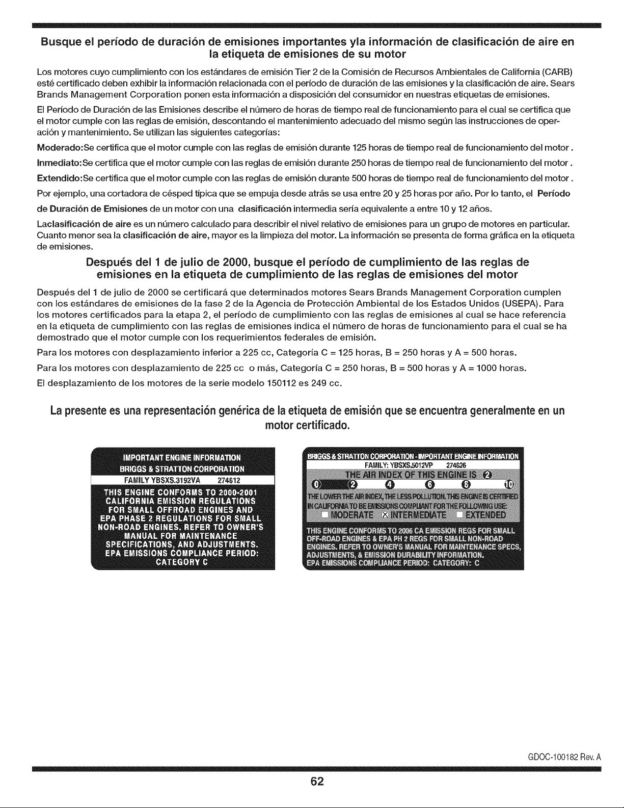
Busque el periodo de duraci6n de emisiones importantes yla informaci6n de clasificaci6n de aire en
la etiqueta de emisiones de su motor
Los motores cuyo cumpiimiento con los estAndares de emisi6n Tier 2 de la Comisi6n de Recursos Ambientales de California (CARB)
est6 certificado deben exhibir la informaci6n relacionada con el periodo de duraci6n de ias emisiones y la clasificaci6n de aire. Sears
Brands Management Corporation ponen esta informaci6n a disposici6n del consumidor en nuestras etiquetas de emisiones.
Ei Periodo de Duraci6n de las Emisiones describe el nQmero de horas de tiempo real de funcionamiento para el cuai se certifica que
el motor cumpie con ias reglas de emisi6n, descontando el mantenimiento adecuado del mismo segQn las instrucciones de oper-
aci6n y mantenimiento. Se utilizan las siguientes categonas:
Moderado:Se certifica que el motor cumpie con las reglas de emisi6n durante 125 horas de tiempo real de funcionamiento del motor.
Inmediato:Se certifica que el motor cumpie con las reglas de emisi6n durante 250 horas de tiempo real de funcionamiento del motor.
Extendido:Se certifica que el motor cumpie con las reglas de emisi6n durante 500 horas de tiempo real de funcionamiento del motor.
Por ejemplo, una cortadora de c6sped tJpica que se empuja desde arras se usa entre 20 y 25 horas por aSo. Por Io tanto, el Periodo
de Duraci6n de Emisiones de un motor con una clasificaci6n intermedia sena equivaiente a entre 10 y 12 aSos.
Laciasificaci6n de aire es un nQmero calculado para describir el nivel relativo de emisiones para un grupo de motores en particular.
Cuanto menor sea la clasificaci6n de aire, mayor es la limpieza del motor. La informaci6n se presenta de forma grAfica en la etiqueta
de emisiones.
Despu_s del 1 de julio de 2000, busque el periodo de cumplimiento de las reglas de
emisiones en la etiqueta de cumplimiento de las reglas de emisiones del motor
Despu6s del 1 de julio de 2000 se certificarA que determinados motores Sears Brands Management Corporation cumplen
con los estAndares de emisiones de la fase 2 de la Agencia de Protecci6n Ambientai de los Estados Unidos (USEPA). Para
los motores certificados para la etapa 2, el periodo de cumplimiento con ias reglas de emisiones al cual se hace referencia
en la etiqueta de cumplimiento con las reglas de emisiones indica el nQmero de horas de funcionamiento para el cual se ha
demostrado que el motor cumple con los requerimientos federales de emisi6n.
Para los motores con desplazamiento inferior a 225 cc, Categoria C = 125 horas, B = 250 horas y A = 500 horas.
Para los motores con desplazamiento de 225 cc o mAs, Categoria C = 250 horas, B = 500 horas y A = 1000 horas.
El desplazamiento de los motores de la serie modelo 150112 es 249 cc.
La presente es una representaci6n gen_rica de la etiqueta de emisi6n que se encuentra generaimente en un
motor certificado.
FAMILYYBSXS.3192VA 274812
GDOC-100182Rev.A
62
Felicitaciones por haber realizado una adquisici6n inteligente. El producto Craftsman® que ha
adquirido esta diseSado y fabricado para brindar muchos aSos de funcionamiento confiable. Pero
como todos los productos a veces puede requerir de reparaciones. Es en ese momento cuando el
disponer de un Acuerdo de protecci6n para reparaciones le puede ahorrar dinero y problemas.
A continuaci6n se detallan los puntos incluidos en el Acuerdo:
[] Servicio experto prestadopor nuestros 10,000 especialistas en reparaciones profesionales
[] Servicio ilirnitado sin cargo para las piezasy la mano de obra en todas las reparacionescubiertas
[] Reernplazo del producto hasta 1500 d61aressi no es posible reparar el producto cubierto
[] Descuento de 25% del precio normal del servicio y de las piezas relacionadas con el mismo que no esten cubiertas
por el acuerdo; ademas, 25% del precio normal de laverificaci6n de mantenimientopreventivo
[] Ayuda r_pida pot tel_fono - Io IlamamosResoluci6n RApida- el apoyo telef6nico de un Chamusca al representante.
Piense en nosotros como el manual "de un dueSohablador."
Una vez adquirido el Acuerdo, puede programar el servicio con tan s61orealizar una Ilamadatelef6nica. Puede Ilamar en
cualquier momento del dia o de la noche o programar un servicio en linea.
ElAcuerdo de Protecci6nde Reparaci6nes una compra sin riesgo. Si usted anula por alguna raz6n durante el periodo de
garantia de producto, proporcionaremos un reembolso Ileno.O, un reembolso prorrateado en cualquier momentodespues
del periodo de garantia de producto expira, iAdquiera hoy su acuerdode protecci6n para reparaciones!
Se aplican determinadas limitaciones y exclusiones. Para obtener informaciTn adicional y precios en los Estados
Unidos Ilame al 1-800-827-6655.
El *Coverage en Canad_ivaria en algunos articulos. Para detalles Ilenos la Ilamada Chamusca Canad_ien 1-800-
361-8885.
Servicio de instalaci6n de Sears
Si desea solicitar la instalaci6n profesional de Sears de aparatosdomesticos, dispositivos paraabrir portones, calentado-
res de agua y otros articulos domesticos importantes, en los Estados Unidos o Canada flame al 1-800-4-MY-HOME®.
63

Your Home
For troubleshooting, product manuals and expert advice:
managernylife
www.managemylife.com
For repair - in your home - of all major brand appliances,
lawn and garden equipment, or heating and cooling systems,
no matter who made it, no matter who sold it!
For the replacement parts, accessories and
owner's manuals that you need to do-it-yourself.
For Sears professional installation of home appliances
and items like garage door openers and water heaters.
1-800-4-MY-HOME ® (1-800-469-4663)
Call anytime, day or night (U.S.A. and Canada)
www.sears.com www.sears.ca
Our Home
For repair of carry-in items like vacuums, lawn equipment,
and electronics, call anytime for the location of your nearest
Sears Parts & Repair Service Center
1-800-488-1222 (U.S.A.) 1-800-469-4663 (Canada)
www.sears.com www.sears.ca
To purchase a protection agreement on a product serviced by Sears:
1-800-827-6655 (U.S.A.) 1-800-361-6665 (Canada)
Para pedir servicio de reparaci6n
a domicilio, y para ordenar piezas:
1-888-SU-HOGAR ®
(1-888-784-6427)
www.sears.com
Au Canada pour service en frangais:
1-800-LE-FOYER Mc
(1-800-533-6937)
www.sears.ca
® Registered Trademark / TMTrademark of KCD IP, LLC in the United States, or Sears Brands, LLC in other countries
® Marca Registrada ! TMMarca de Fabrica de KCD IP, LLC en Estados Unidos, o Sears Brands, LLC in otros paises
MCMarque de commerce ! MDMarque deposee de Sears Brands, LLC

