
Operator's Manual
CRRF[SM ®
675 Series Engine
POWER PROPELLED YARD VACUUM
Model No. 247.77366
CAUTION: Before using
this product, read this
manual and follow all
safety rules and operating
instructions.
o SAFETY
ASSEMBLY
OPERATION
MAINTENANCE
PARTS LIST
o ESPANOL
Sears Brands Management Corporation, Hoffman Estates, IL 60179, U.S.A.
Visit our web site: www.craftsman.com
FORMNO.769-06238
7/13/2010
WarrantyStatement..................................Page2
SafeOperationPractices..........................Pages3-6
SafetyLabels............................................Page7
Assembly..................................................Pages8-11
Operation..................................................Pages12-15
ServiceandMaintenance.........................Pages16-21
Off-SeasonStorage..................................Page22
TroubleShooting.......................................Page23
PartsList...................................................Page24-34
RepairProtectionAgreement...................Page38
Espa_ol.....................................................Page39
ServiceNumbers......................................BackCover
CRAFTSMANTWOYEARFULL WARRANTY
FORTWOYEARSfromthedateofpurchase,thisproductiswarrantedagainstanydefectsinmaterialor workmanship,Defectiveproductwill
receivefree repairor free replacementif repairis unavailable.
Thiswarrantyisvoid ifthisproductiseverusedwhile providingcommercialservicesor ifrentedto anotherperson.
For warrantycoverage details to obtain repairor replacement,visit the website: www.craftsman.com
This warranty covers ONLYdefects in material and workmanship. Warranty coverage does NOTinclude:
• Expendableitemsthat can wearoutfromnormalusewithinthewarrantyperiod,includingbut not limitedto sparkplug,air cleaner,belt,and
oilfilter.
• Standardmaintenanceservicing,oil changes,or tune-ups.
• Tire replacementor repaircausedby puncturesfrom outsideobjects,such as nails,thorns,stumps,or glass.
• Tireor wheelreplacementor repairresultingfromnormalwear,accident,orimproperoperationor maintenance.
• Repairsnecessarybecauseof operatorabuse,includingbutnot limitedto, damagecausedbyover-speedingthe engine,orby impacting
objectsthat bendthe frame.
• Repairsnecessarybecauseof operatornegligence,includingbut not limitedto,electricalandmechanicaldamagecausedby improper
storage,failureto usethe propergradeand amountof engineoil, or failureto maintainthe equipmentaccordingto the instructionscontained
inthe operator'smanual.
• Engine(fuelsystem)cleaningor repairscausedbyfuel determinedto becontaminatedoroxidized(stale).in general,fuel shouldbeused
within30 daysof itspurchasedate.
• Normaldeteriorationand wearof the exteriorfinishes,or productlabel replacement.
Thiswarrantygivesyou specificlegalrights,and you mayalso haveotherrightswhich vary from stateto state.
Sears Brands Management Corporation, Hoffman Estates, IL 60179
EngineSeries: 675
EngineOilType: SAE30
EngineOilCapacity: 18ounces
FuelCapacity: 1 1/2 Quarts
SparkPlug: Champion®RJ19LM
SparkPlugGap: .020"
Model Number.................................................................
Serial Number .................................................................
Dateof Purchase.............................................................
Recordthe modelnumber,serialnumber
anddateof purchaseabove
© Sears Brands,LLC 2
Thissymbolpointsout importantsafetyinstructionswhich,if not
followed,couldendangerthe personalsafetyand/orpropertyof
yourselfand others. Readandfollowall instructionsin this manual
beforeattemptingto operatethismachine.Failureto complywith
theseinstructionsmay resultin personalinjury.Whenyou seethis
symbol,HEEDITSWARNING!
CALIFORNIA PROPOSITION 65
EngineExhaust,someof itsconstituents,and certainvehicle
componentscontainoremitchemicalsknownto Stateof California
to cause cancerand birthdefectsor other reproductiveharm.
Thismachinewasbuilt to beoperatedaccordingto the safe opera-
tion practicesin this manual.As withany type of powerequipment,
carelessnessor error on the part of the operatorcan resultin
seriousinjury.Thismachineis capableof amputatingfingers,hands,
toesandfeetandthrowingdebris.Failureto observethe following
safetyinstructionscouldresultin seriousinjuryor death.
Your Responsibility--Restrict the useof thispowermachineto
personswho read,understandandfollowthewarningsand instruc-
tionsinthismanualandon the machine.
SAVETHESEINSTRUCTIONS!
TRAINING
• Read,understand,andfollowall instructionson the machineand
in themanualbeforeattemptingto assembleandoperate.Keep
thismanualina safeplacefor futureandregularreferenceandfor
orderingreplacementparts.
• Readthe Operator'sManualand followall warningsand safety
instructions.Failureto doso can resultin seriousinjuryto the
operatorand/orbystanders.Forquestionscall, 1-800-4MY-
HOME.
• Be familiarwith all controlsand their properoperation.Knowhow
to stop the machineanddisengagethemquickly.
• Neverallowchildrenunder16yearsof age to operatethis
machine.Children16andovershouldreadandunderstandthe
instructionsand safe operationpracticesin thismanualandon
the machineandbe trainedandsupervisedby anadult.
• Neverallowadultsto operatethis machinewithoutproper
instruction.
• Keepbystanders,pets,andchildrenat least75feetfromthe
machinewhile it is in operation.Stopmachineif anyoneenters
the area.
• Neverrun an engine indoorsor ina poorlyventilatedarea.Engine
exhaustcontainscarbonmonoxide,an odorlessand deadlygas.
• Do not puthandsand feet near rotatingpartsor in the feeding
chambersand dischargeopening.Contactwiththe rotating
impellercan amputatefingers,hands,andfeet.
• Neverattemptto unclogeitherthe feed intakeordischarge
opening,removeor emptybag,or inspectand repairthe machine
whilethe engineis running.Shutthe engineoff and wait untilall
movingpartshavecome to a completestop.Disconnectthe spark
plugwireandgroundit againstthe engine.
PREPARATION
• Thoroughlyinspectthearea wherethe equipmentis to be used.
Removeall rocks,bottles,cans,or otherforeignobjectswhich
could be pickedup or thrownand cause personalinjuryor
damageto the machine.
• Alwayswear safetyglassesor safetygogglesduringoperation
andwhile performingan adjustmentor repair,to protectyour
eyes.Thrownobjectswhich ricochetcan cause seriousinjuryto
the eyes.
• Wearsturdy,rough-soledworkshoesandclose-fittingslacksand
shirts.Loosefittingclothesor jewelrycan becaughtin movable
parts.Neveroperatethismachineinbarefeetorsandals.Wear
leatherworkgloveswhenfeedingmaterialin the chipperchute.
• Beforestarting,checkallboltsandscrewsfor propertightnessto
besurethe machineis insafeworkingcondition.Also,visually
inspectmachinefor any damageat frequentintervals.
• Maintainor replacesafetyandinstructionslabels,as necessary.
3
Safe Handling of Gasoline:
Toavoidpersonalinjuryor propertydamageuseextremecare in
handlinggasoline.Gasolineis extremelyflammableand the vaporsare
explosive.Seriouspersonalinjurycan occurwhengasolineis spilled
onyourselfor yourclotheswhichcan ignite.Washyour skinand
changeclothesimmediately.
• Use onlyan approvedgasolinecontainer.
• Neverfill containersinsidea vehicleor ona truckor trailerbed
witha plasticliner.Alwaysplacecontainersonthe groundaway
fromyour vehiclebeforefilling.
• Whenpractical,removegas-poweredequipmentfromthe truck
ortrailerand refuelitonthe ground.If this is notpossible,then
refuelsuchequipmenton a trailerwitha portablecontainer,rather
thanfroma gasolinedispensernozzle.
• Keepthe nozzleincontactwiththe rimof the fuel tank or
containeropeningat alltimes untilfuelingis complete.Do not use
a nozzlelock-opendevice.
• Extinguishallcigarettes,cigars,pipesand other sourcesof
ignition.
• Neverfuel machineindoors.
• Neverremovegas capor addfuel whilethe engineishot or run-
ning.Allowengineto cool at leasttwo minutesbeforerefueling.
• Neveroverfill fueltank. Fill tankto nomorethan1/2inchbelow
bottomof filler neck to allowspacefor fuel expansion.
• Replacegasolinecapand tighten securely.
• If gasolineisspilled,wipe itoff theengineandequipment.Move
unitto anotherarea.Wait5 minutesbeforestartingthe engine.
• To reducefire hazards,keepmachinefreeof grass, leaves,or
otherdebrisbuild-up.Cleanup oil orfuel spillageand removeany
fuel soakeddebris.
• Neverstorethe machineorfuel containerinsidewherethereis an
openflame,sparkor pilotlightas on a water heater,space heater,
furnace,clothesdryer or othergas appliances.
OPERATION
• Do not puthandsand feet near rotatingpartsor in thefeeding
chambersand dischargeopening.Contactwiththe rotating
impellercan amputatefingers,hands,andfeet.
• Beforestartingthe machine,makesurethe chipperchute,feed
intake,and cuttingchamberare emptyandfreeof all debris.
• Thoroughlyinspectall materialto be shreddedandremoveany
metal,rocks,bottles,cans,or otherforeignobjectswhichcould
causepersonalinjuryor damageto the machine.
• Ifthe impellerstrikesa foreignobjector if yourmachineshould
start makingan unusualnoiseorvibration,immediatelyshut
the engineoff. Allowthe impellerto cometoa completestop.
Disconnectthe sparkplugwire,grounditagainstthe engineand
performthe followingsteps:
a. Inspectfor damage.
b. Repairor replaceanydamagedparts.
c. Checkfor anyloose partsandtightento assurecontinued
safeoperation.
• Donot allowanaccumulationof processedmaterialto buildupin
the dischargearea.Thiscan preventproperdischargeand result
inkickbackof materialthroughthe feedopening.
• Donot attemptto shredorchip materiallargerthanspecified
on the machineor in this manual.Personalinjuryor machine
damagecould result.
• Neverattemptto unclogeitherthe feedintakeor discharge
openingwhilethe engineis running.Shuttheengineoff,waituntil
all movingpartshavestopped,disconnectthe sparkplugwireand
grounditagainsttheenginebeforeclearingdebris.
• Neveroperatewithoutvacuumbag and dischargechute properly
attachedtothe machine.Neveremptyor changevacuumbag
whilethe engineisrunning.Vacuumbagmustbe keptclosedat
all timesduringoperation.
• Neveroperatewithouteitherthe inletnozzleor optionalhose
attachment(if applicable)properlyattachedto the machine.
Neverattemptto attachor changeeitherattachmentwhile the
engineis running.
• Keepallguards,deflectorsand safetydevicesin placeand
operatingproperly.
• Keepyourfaceandbodybackandto the sideof the chipper
chutewhilefeedingmaterialintothe machineto avoidaccidental
kickbackinjuries.
• Neveroperatethis machinewithoutgoodvisibilityorlight.Always
be sureof yourfootingand keepa firmholdon the handles.
• Donot operatethis machineon a paved,gravelor non-level
surface.
• Donot operatethis machinewhileunderthe influenceof alcohol
or drugs.
• Mufflerandenginebecomehot and cancause a burn.Do not
touch.
• Neverpick up or carry machinewhilethe engineis running.
• Ifsituationsoccur whichare notcoveredinthis manual,use care
andgoodjudgement.ContactCustomerSupportforassistance
andthe nameof the nearestservicedealer.
4
MAINTENANCE & STORAGE
• Nevertamperwith safetydevices.Checktheirproperoperation
regularly.
• Checkboltsand screwsfor propertightnessat frequentintervals
to keepthe machinein safeworkingcondition.Also, visually
inspectmachinefor anydamageand repair,if needed.
Beforecleaning,repairing,or inspecting,stopthe engineand
makecertainthe impellerand allmovingpartshavestopped.
Disconnectthe sparkplugwire and groundit againstthe engine
to preventunintendedstarting.
Do notchangetheenginegovernorsettingsor overspeedthe
engine.Thegovernorcontrolsthe maximumsafeoperatingspeed
of the engine.
Maintainor replacesafetyandinstructionlabels,as necessary.
Followthismanualfor safeloading,unloading,transporting,and
storageof thismachine.
Neverstorethe machineorfuel containerinsidewherethereis an
openflame,spark orpilot lightsuchas a waterheater,furnace,
clothesdryer,etc.
Allowmachineto cool at least5 minutesbeforestoring.
• Alwaysreferto the operator'smanualfor properinstructionson
off-seasonstorage.
• If thefuel tankhasto bedrained,do this outdoors.
• Observeproperdisposallawsand regulationsfor gas,oil,etc. to
protectthe environment.
• Accordingto the ConsumerProductsSafetyCommission(CPSC)
andthe U.S.EnvironmentalProtectionAgency(EPA),thisproduct
hasan AverageUsefulLifeof seven(7)years,or 60hoursof
operation.At the end of theAverageUsefulLifehavethe machine
inspectedannuallybyan authorizedservicedealerto ensurethat
allmechanicalandsafetysystemsare workingproperlyand not
wornexcessively.Failureto do so can resultinaccidents,injuries
ordeath.
DO NOT MODIFY ENGINE
Toavoidseriousinjuryordeath,donot modifyenginein anyway.
Tamperingwiththe governorsettingcan leadto a runawayengineand
causeit to operateat unsafespeeds.Nevertamperwithfactorysetting
of enginegovernor.
NOTICE REGARDING EMISSIONS
Engineswhich are certifiedtocomplywith Californiaand federal
EPAemissionregulationsfor SORE(SmallOff RoadEquipment)are
certifiedto operateon regularunleadedgasoline,and mayinclude
the followingemissioncontrolsystems:EngineModification(EM),
OxidizingCatalyst(OC), SecondaryAir Injection(SAI)and ThreeWay
Catalyst(TWO)if so equipped.
SPARK ARRESTOR
Thismachineis equippedwithan internalcombustionengineand
shouldnotbe usedonor nearanyunimprovedforest-covered,
brushcoveredor grass-coveredland unlessthe engine'sexhaust
systemis equippedwitha sparkarrestormeetingapplicablelocal or
statelaws(if any).
Ifa sparkarrestoris used, it shouldbe maintainedin effectiveworking
orderby theoperator.Inthe State of Californiathe aboveis required
bylaw (Section4442of the CaliforniaPublicResourcesCode).Other
statesmayhavesimilarlaws. Federallawsapplyonfederallands.
A sparkarrestorfor the muffleris availablethroughyournearestSears
PartsandRepairServiceCenter.
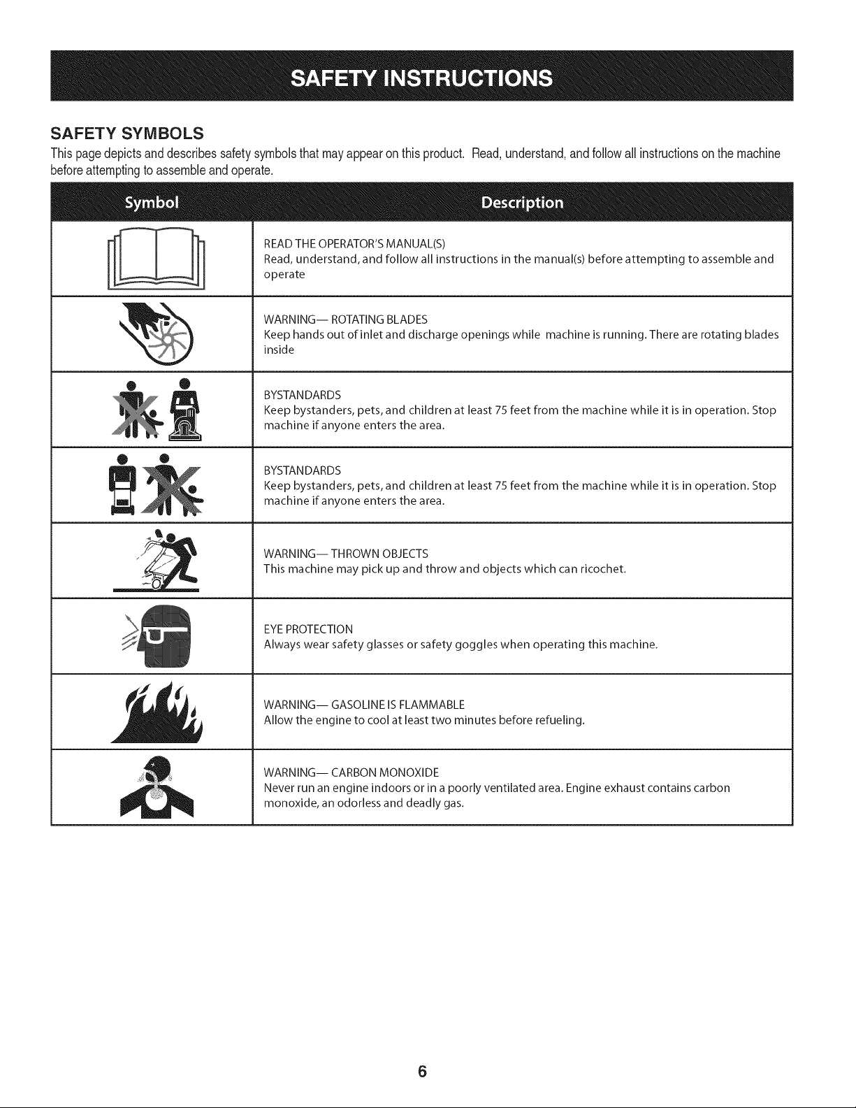
SAFETY SYMBOLS
Thispagedepictsanddescribessafetysymbolsthat mayappear on this product. Read,understand,andfollowall instructionson the machine
beforeattemptingto assembleandoperate.
i
i
• ®
® •
llm
il
READ THE OPERATOR'S MANUAL(S)
Read, understand, and follow all instructions in the manual(s) before attempting to assemble and
operate
WARNING-- ROTATING BLADES
Keep hands out of inlet and discharge openings while machine is running. There are rotating blades
inside
BYSTAN DARDS
Keep bystanders, pets, and children at least 75 feet from the machine while it is in operation. Stop
machine if anyone enters the area.
BYSTAN DARDS
Keep bystanders, pets, and children at least 75 feet from the machine while it is in operation. Stop
machine if anyone enters the area.
WARNING-- THROWN OBJECTS
This machine may pick up and throw and objects which can ricochet.
EYE PROTECTION
Always wear safety glasses or safety goggles when operating this machine.
WARNING-- GASOLINE IS FLAMMABLE
Allow the engine to cool at least two minutes before refueling.
WARNING-- CARBON MONOXIDE
Never run an engine indoors or in a poorly ventilated area. Engine exhaust contains carbon
monoxide, an odorless and deadly gas.
6
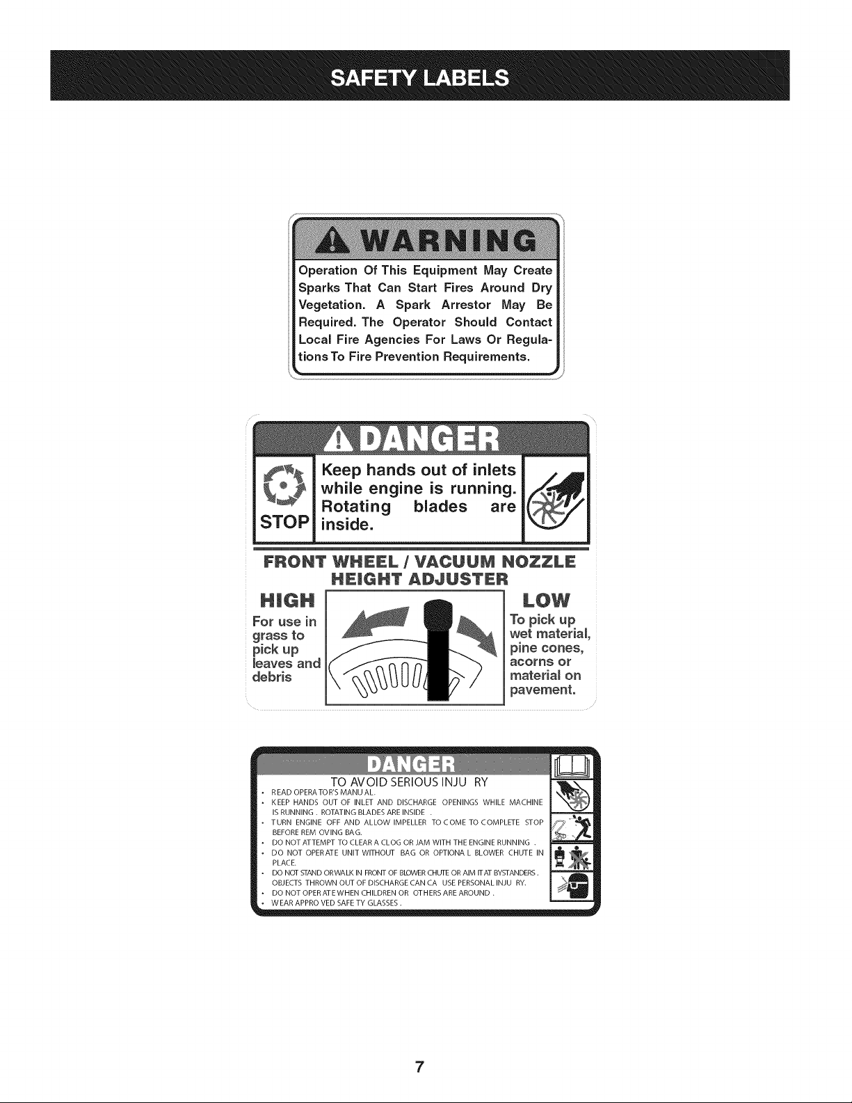
Operation Of This Equipment May Create
Sparks That Can Start Fires Around Dry
Vegetation. A Spark Arrestor May Be
Required. The Operator Should Contact
Local Fire Agencies For Laws Or Regula=
tions To Fire Prevention Requirements.
STOP
Keep hands out of inlets
while engine is running.
Rotating blades are
inside.
FRONT WHEEL / VACUUM NOZZLE
HEmGHT ADJUSTER
For use in
grass to
pickup
_eaves and
debris
To pick up
wet material
pine cones_
acorns Or
materia_ on
pavement.
TO AVOID SERIOUS INJU RY
R EAD OPERA TO R'S MANU AL.
KEEP HANDS OUT OF INLET AND DISCHARGE OPENINGS WHILE MACHINE
IS RUNNING . ROTATING BLADES ARE INSIDE .
TURN ENGINE OFF AND ALLOW IMPELLER TOCOME TOCOMPLETE STOP
BEFORE REM OVlNG BAG.
DO NOT ATTEMPT TO CLEAR A CLOG OR JAM WITH THE ENGINE RUNNING .
DO NOT OPERATE UNIT WITHOUT BAG OR OPTIONA L BLOWER CHUTE IN
PLACE.
DO NOT STAND ORWALK IN FRONT OF BLOWER CHUTE OR AIM ITAT BYSTANDERS.
OBJECTS THROWN OUT OF DISCHARGE CAN CA USE PERSONAL INJU RY.
DO NOT OPERATEWHEN CHILDREN OR OTHERS ARE AROUND .
WEAR APPRO VED SAFE TY GLASSES.
7
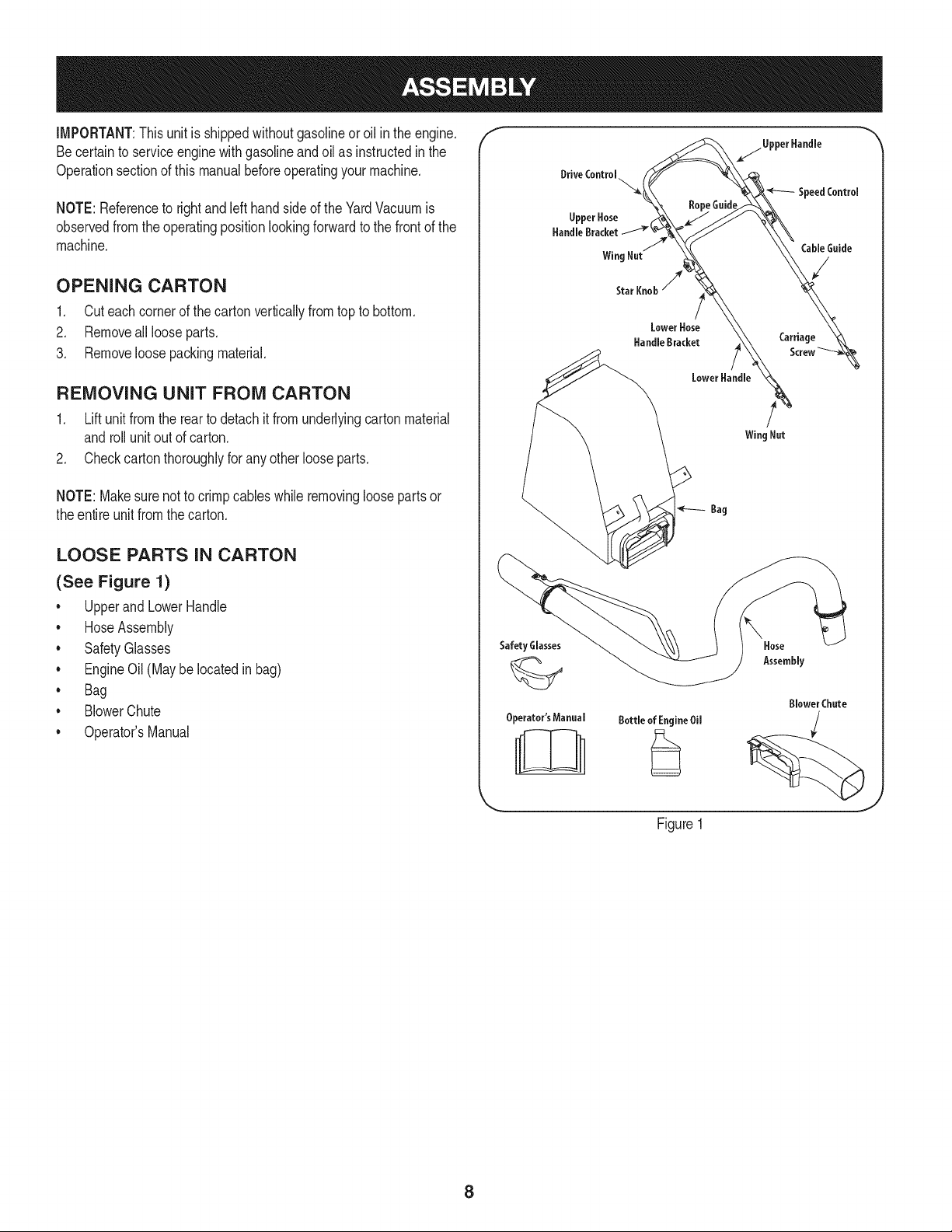
IMPORTANT:Thisunit isshippedwithoutgasolineoroil inthe engine.
Becertainto serviceenginewithgasolineandoilas instructedin the
Operationsectionof this manualbeforeoperatingyourmachine.
NOTE:Referenceto rightand lefthandsideof the YardVacuumis
observedfromthe operatingpositionlookingforwardto the frontof the
machine.
OPENING CARTON
1. Cut eachcornerof the cartonverticallyfromtop to bottom.
2. Removeall looseparts.
3. Removeloosepackingmaterial.
REMOVING UNIT FROM CARTON
1. Lift unit fromthe rearto detachit from underlyingcartonmaterial
androllunit out of carton.
2. Checkcartonthoroughlyfor anyotherlooseparts.
NOTE:Makesurenot to crimp cableswhile removingloosepartsor
theentire unitfromthecarton.
LOOSE PARTS IN CARTON
(See Figure 1)
• Upperand LowerHandle
• HoseAssembly
• SafetyGlasses
• EngineOil (May be located in bag)
• Bag
• BlowerChute
• Operator'sManual
f
Safety Glasses
Operator'sManual
Bottle of EngineOil
Figure1
\
Hose
Assembly
Blower Chute
J
8
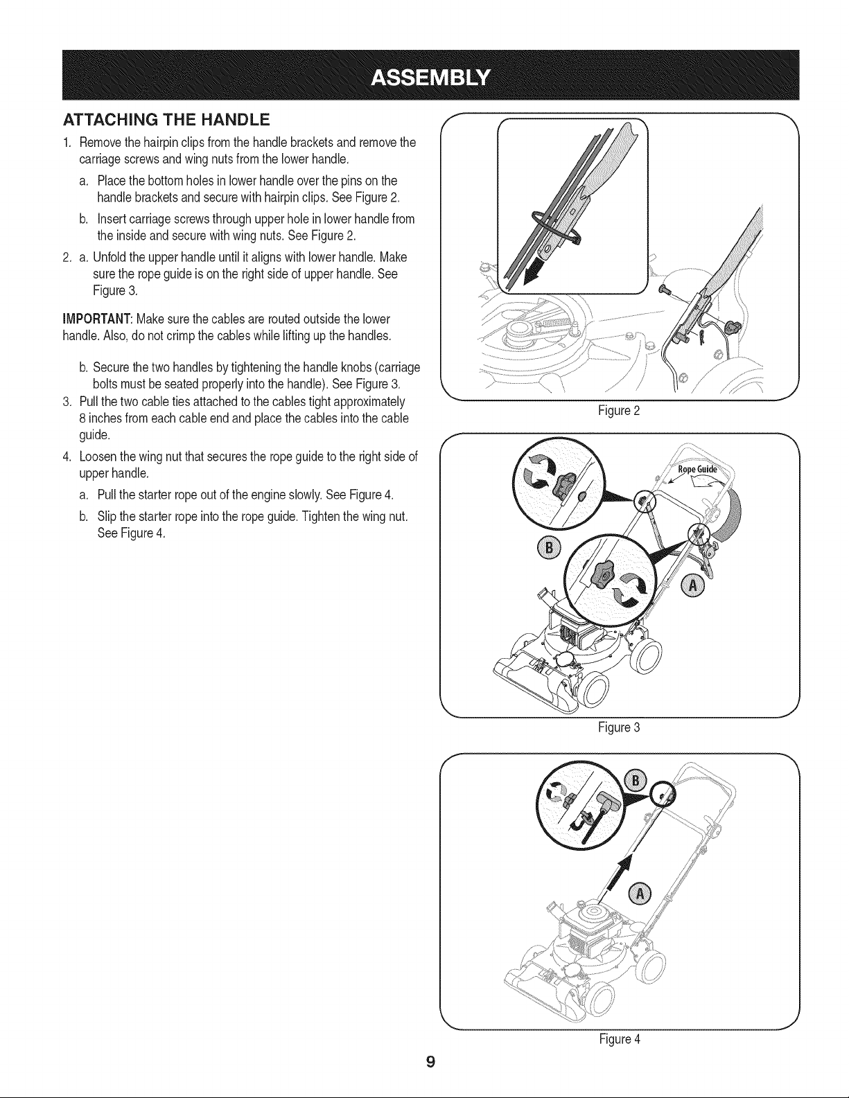
ATTACHING THE HANDLE
1. Removethehairpinclipsfromthe handlebracketsand removethe
carriagescrewsand wingnutsfromthe lowerhandle.
a. Placethe bottomholesinlowerhandleoverthe pinson the
handlebracketsand securewith hairpinclips. See Figure2.
b. insertcarriagescrewsthroughupperholeinlowerhandlefrom
the insideand securewith wingnuts.SeeFigure2.
2. a. Unfoldthe upperhandleuntil italignswithlowerhandle.Make
surethe ropeguideis on the rightside of upperhandle.See
Figure3.
IMPORTANT:Makesurethe cablesareroutedoutsidethe lower
handle.Also, do not crimpthe cableswhile liftingupthe handles.
.
.
b. Securethe two handlesbytighteningthe handleknobs(carriage
boltsmustbeseatedproperlyintothe handle).See Figure3.
Pullthetwo cabletiesattachedto the cablestightapproximately
8 inchesfromeachcableendandplacethe cables intothe cable
guide.
Loosenthe wingnut that securesthe rope guideto the rightsideof
upperhandle.
a. Pullthe starterropeout of the engineslowly.SeeFigure4.
b. Slipthe starterropeinto the ropeguide.Tightenthe wingnut.
SeeFigure4.
Figure2
Figure3
J
9
Figure4
J
f
Figure5
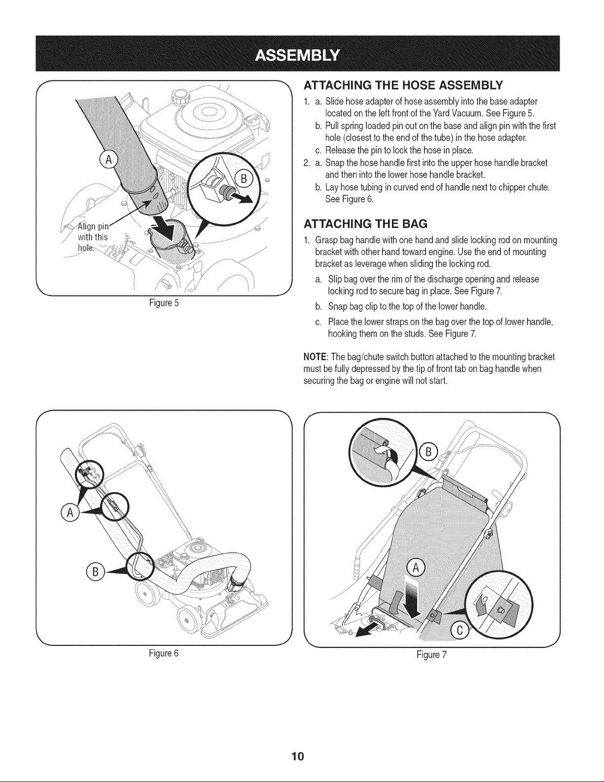
_, ATTACHING THE HOSE ASSEMBLY
1. a. Slidehoseadapterof hoseassemblyintothe baseadapter
locatedon the left front of theYardVacuum.See Figure5.
b. Pullspringloadedpin out on the baseand align pin with the first
hole(closestto the endof the tube) inthe hoseadapter.
c. Releasethe pin to lockthe hosein place.
2. a. Snapthe hosehandlefirst intothe upperhose handlebracket
andthen intothe lowerhosehandlebracket.
b. Layhosetubingin curved end of handlenextto chipperchute.
SeeFigure6.
ATTACH I NG TH E BAG
Graspbaghandlewithonehandandslide lockingrod on mounting
bracketwith otherhandtowardengine.Usethe endof mounting
bracketas leveragewhenslidingthe lockingrod.
a. Slipbagoverthe rim of the dischargeopeningandrelease
lockingrodto securebag in place.See Figure7.
b. Snapbagclipto the topof the lowerhandle.
c. Placethe lowerstrapson the bagoverthe topof lowerhandle,
hookingthemon the studs.SeeFigure7.
NOTE:The bag/chuteswitchbuttonattachedto the mountingbracket
must be fully depressedby thetip of fronttab on bag handlewhen
securingthe bagor enginewill not start.
Figure6
Figure7
10
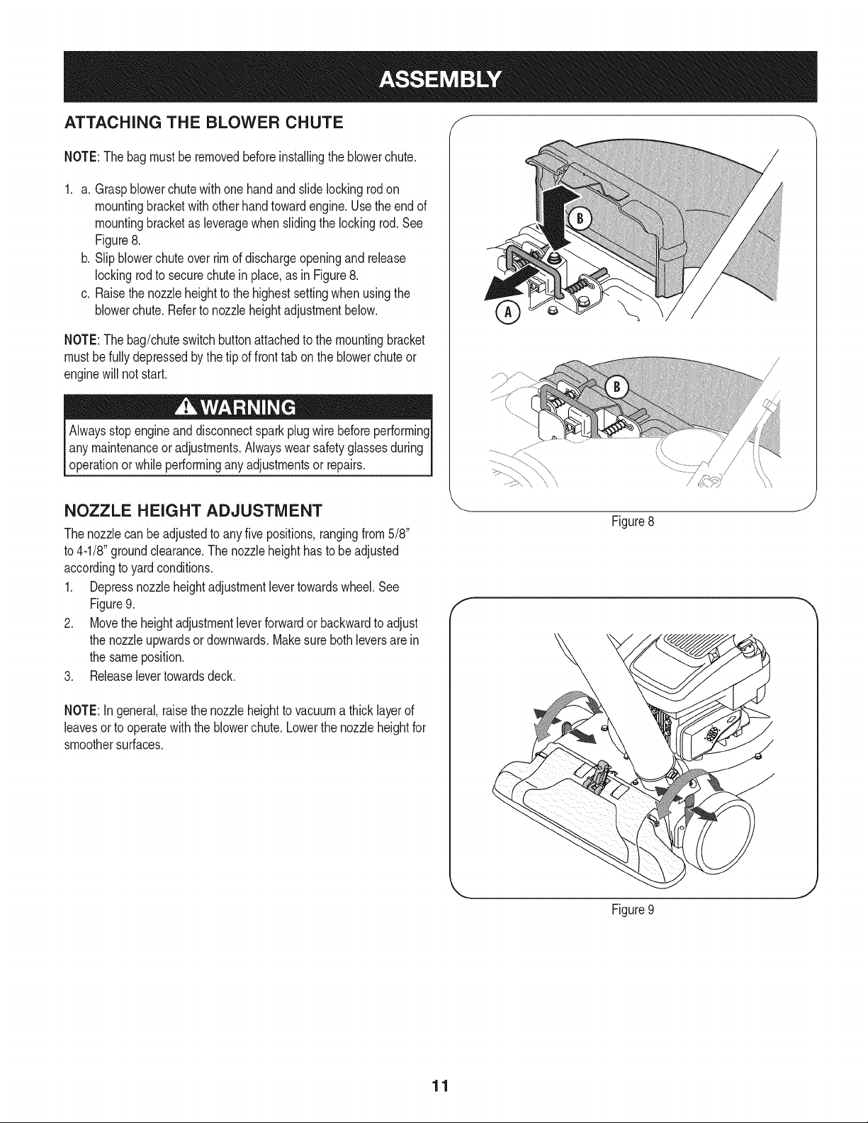
ATTACHING THE BLOWER CHUTE f
NOTE:Thebagmust beremovedbeforeinstallingthe blowerchute.
1. a. Graspblowerchutewithone handandslide lockingrod on
mountingbracketwith otherhand towardengine.Usethe end of
mountingbracketas leveragewhenslidingthe lockingrod.See
Figure8.
b. Slipblowerchuteoverrimof dischargeopeningand release
lockingrodto securechutein place,as in Figure8.
c. Raisethe nozzleheightto the highestsettingwhen usingthe
blowerchute.Referto nozzleheightadjustmentbelow.
NOTE:Thebag/chuteswitchbuttonattachedto the mountingbracket
mustbefullydepressedbythe tip of fronttab on the blowerchuteor
enginewill not start.
Alwaysstopengineanddisconnectsparkplugwire beforeperforming
any maintenanceoradjustments.Alwayswear safetyglassesduring
operationor whileperformingany adjustmentsor repairs.
NOZZLE HEIGHT ADJUSTMENT
Thenozzlecan beadjustedto anyfive positions,rangingfrom5/8"
to 4-1/8"groundclearance.The nozzleheighthasto be adjusted
accordingto yardconditions.
1. Depressnozzleheightadjustmentlevertowardswheel.See
Figure9.
2. Movethe heightadjustmentleverforwardor backwardto adjust
the nozzleupwardsor downwards.Makesure bothleversare in
the sameposition.
3. Releaselevertowardsdeck.
NOTE:In general,raisethe nozzleheightto vacuuma thicklayerof
leavesorto operatewiththeblowerchute.Lowerthe nozzleheightfor
smoothersurfaces.
f
\\
Figure8
J
Figure9
J
11
f
Drive Control
Speed Thr( Control Choke Control
Starter
Lower
Hose
Bracket
HoseAssembl'
Hose
Blower Chipper
Chute Chute
Bag
Bag Handle
Oil Fill
Gasoline Fill
)ark Plug Wire
Nozzle/Hose
Lever
Nozzle
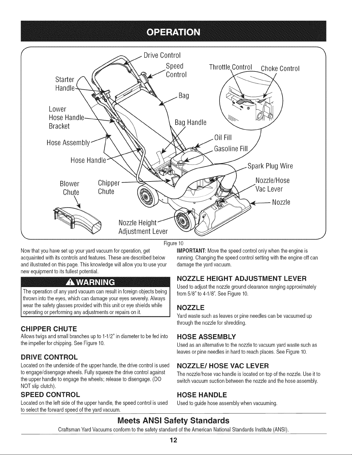
Nowthat youhavesetup youryardvacuumfor operation,get
acquaintedwith itscontrolsandfeatures.These are describedbelow
andillustratedon this page.This knowledgewill allowyou to useyour
newequipmentto its fullestpotential.
Theoperationof anyyard vacuumcan resultin foreignobjectsbeing
thrownintothe eyes,whichcan damageyoureyesseverely.Always
I wearthe safetyglassesprovidedwiththisunit or eye shieldswhile
[operatingor performinganyadjustmentsor repairson it.
Nozzle Heig
Adjustment Lever
J
Figure10
iMPORTANT:Movethe speedcontrolonlywhenthe engineis
running.Changingthe speedcontrolsettingwith theengineoffcan
damagethe yardvacuum.
CHIPPER CHUTE
Allowstwigsandsmallbranchesupto 1-1/2"in diameterto be fed into
the impellerfor chipping.SeeFigure10.
DRIVE CONTROL
Locatedon the undersideof the upperhandle,the drivecontrolis used
to engage/disengagewheels.Fullysqueezethe drivecontrolagainst
the upperhandleto engagethe wheels;releaseto disengage.(DO
NOTslip clutch).
SPEED CONTROL
Locatedon the left side of the upperhandle,the speedcontrolis used
to selectthe forwardspeedof the yardvacuum.
NOZZLE HEIGHT ADJUSTMENT LEVER
Usedto adjustthe nozzlegroundclearancerangingapproximately
from5/8" to 4-1/8".See Figure10.
NOZZLE
Yardwastesuchas leavesorpine needlescan bevacuumedup
throughthe nozzlefor shredding.
HOSE ASSEMBLY
Usedas an alternativeto thenozzleto vacuumyardwastesuchas
leavesor pineneedlesin hardto reachplaces.SeeFigure10.
NOZZLE/HOSE VAC LEVER
The nozzle/hosevachandleis locatedon topof the nozzle.Useit to
switchvacuumsuctionbetweenthe nozzleandthe hoseassembly.
HOSE HANDLE
Usedto guidehoseassemblywhenvacuuming.
Meets ANSI Safety Standards
CraftsmanYardVacuumsconformto the safetystandardof the AmericanNationalStandardsinstitute(ANSi).
12
BAG HANDLE
Usedto grasp baginorderto assistinattaching,removing,and
emptyingbag.See Figure10.
BAG
Collectsshreddedmaterialfed throughthe chipperchuteorvacuumed
throughthe nozzleor hose.
BLOWER CHUTE
Whenattachedto unit,the blowerchuteisusedto dischargeyard
wastesuchas leaves,pineneedle,or smalltwigsacrossyard.
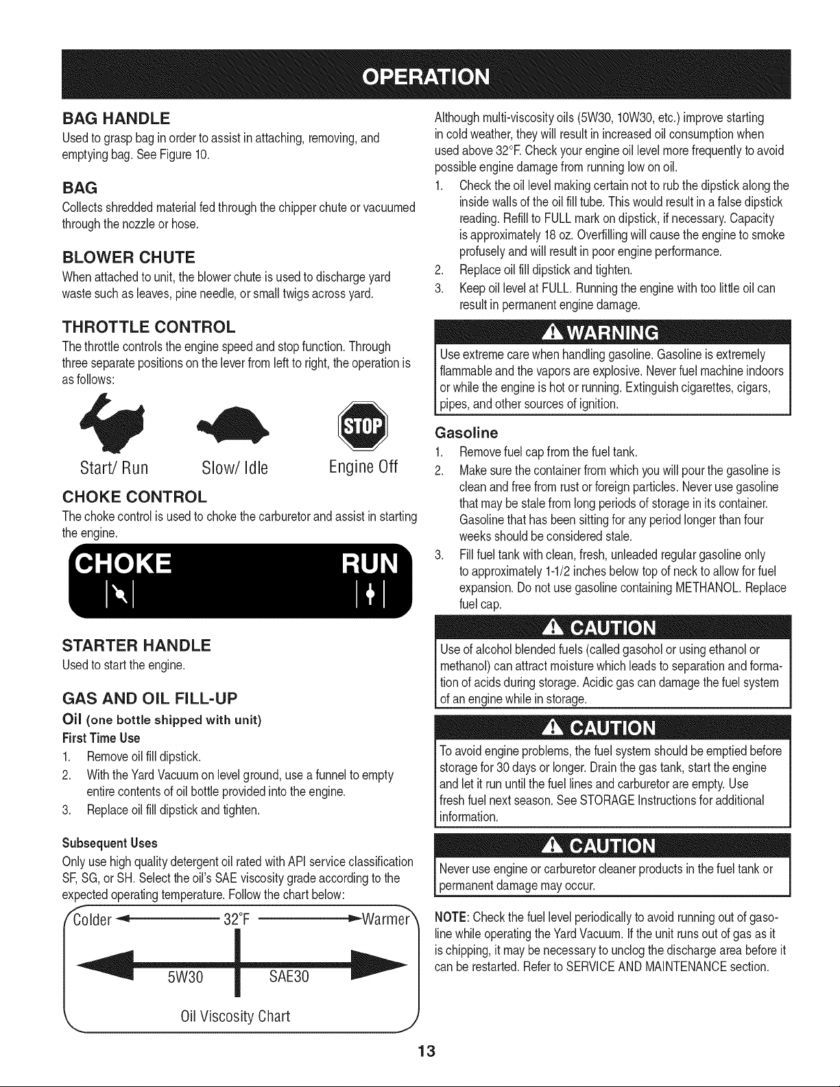
THROTTLE CONTROL
Thethrottlecontrolsthe enginespeedandstopfunction.Through
threeseparatepositionson the leverfromleftto right,the operationis
as follows:
Althoughmulti-viscosityoils (5W30, 10W30,etc.) improvestarting
incoldweather,they will resultin increasedoil consumptionwhen
usedabove32°E Checkyourengineoil levelmorefrequentlyto avoid
possibleenginedamagefrom runninglow onoil.
1. Checkthe oil level makingcertainnotto rubthedipstickalongthe
insidewalls of the oil fill tube.Thiswouldresultin afalsedipstick
reading.Refillto FULLmarkondipstick,if necessary.Capacity
isapproximately18oz.Overfillingwill causethe engineto smoke
profuselyand will resultin poorengineperformance.
2. Replaceoil fill dipstickandtighten.
3. Keepoillevelat FULL.Runningthe enginewith too littleoil can
resultin permanentenginedamage.
Useextremecarewhen handlinggasoline.Gasolineis extremely
flammableand thevaporsare explosive.Neverfuel machineindoors
or whilethe engineis hot or running.Extinguishcigarettes,cigars,
pipes,andother sourcesof ignition.
Start/Run Slow/Idle Engine Off
CHOKE CONTROL
Thechokecontrolis usedto chokethe carburetorandassistinstarting
the engine.
STARTER HANDLE
Usedto startthe engine.
GAS AND OiL FILL-UP
Oil (one bottle shipped with unit)
First TimeUse
1. Removeoilfill dipstick.
2. With theYardVacuumon levelground,usea funnelto empty
entirecontentsof oil bottle providedintothe engine.
3. Replaceoil fill dipstickandtighten.
Subsequent Uses
Onlyuse highqualitydetergentoil ratedwith APIserviceclassification
SF,SG,or SH.Selectthe oil'sSAEviscositygradeaccordingto the
expectedoperatingtemperature.Followthe chart below:
/_Colder_ 32°F _Warme_
0il Viscosity Chart
J
Gasoline
1. Removefuel capfromthe fueltank.
2. Makesurethe containerfromwhichyou will pourthe gasolineis
cleanandfree from rust or foreignparticles.Neverusegasoline
thatmaybe stalefromlongperiodsof storagein its container.
Gasolinethat has beensittingfor any periodlongerthan four
weeksshouldbeconsideredstale.
3. Fillfuel tankwithclean,fresh,unleadedregulargasolineonly
to approximately1-1/2inchesbelowtopof neckto allowfor fuel
expansion.Do notuse gasolinecontainingMETHANOL.Replace
fuel cap.
Useof alcoholblendedfuels(calledgasoholor usingethanolor
methanol)canattractmoisturewhich leadsto separationandforma-
tion of acidsduringstorage.Acidic gascan damagethe fuelsystem
of anenginewhilein storage.
Toavoidengineproblems,thefuel systemshouldbeemptiedbefore
storagefor30 daysorlonger.Drainthe gas tank,start theengine
andlet it rununtilthe fuel linesand carburetorare empty.Use
freshfuelnextseason.See STORAGEInstructionsfor additional
nformaton.
mayoccur.
NOTE:Checkthe fuellevel periodicallyto avoidrunningout of gaso-
linewhile operatingthe YardVacuum.Ifthe unit runsout of gas as it
ischipping,it maybe necessaryto unclogthe dischargearea beforeit
can be restarted.Referto SERVICEAND MAINTENANCEsection.
13
TopView
iiii Front Tab i ..............................
BagYC_hutei/
Switch Wire /
/
/
Figure11
Choke Control
Figure12
f
Whenmovingthrottlecontrol lever,be carefulof heatedsurfacesand
sharpedgeson mufflerguard.
TO START ENGINE
1. Attachsparkplugwire and rubberbootto sparkplug.
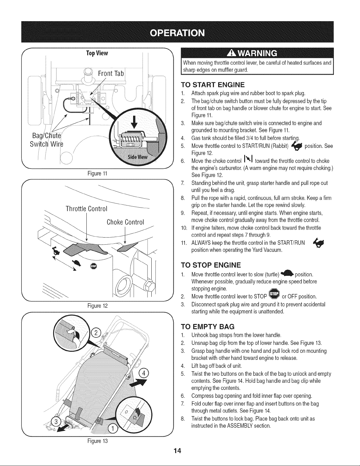
2. The bag/chuteswitch buttonmustbe fully depressedbythe tip
of front tab on baghandleor blowerchutefor engineto start. See
Figure11.
3. Makesurebag/chuteswitchwire is connectedto engineand
groundedto mountingbracket.SeeFigure11.
4. Gas tankshouldbe filled3/4 to full beforestarting.
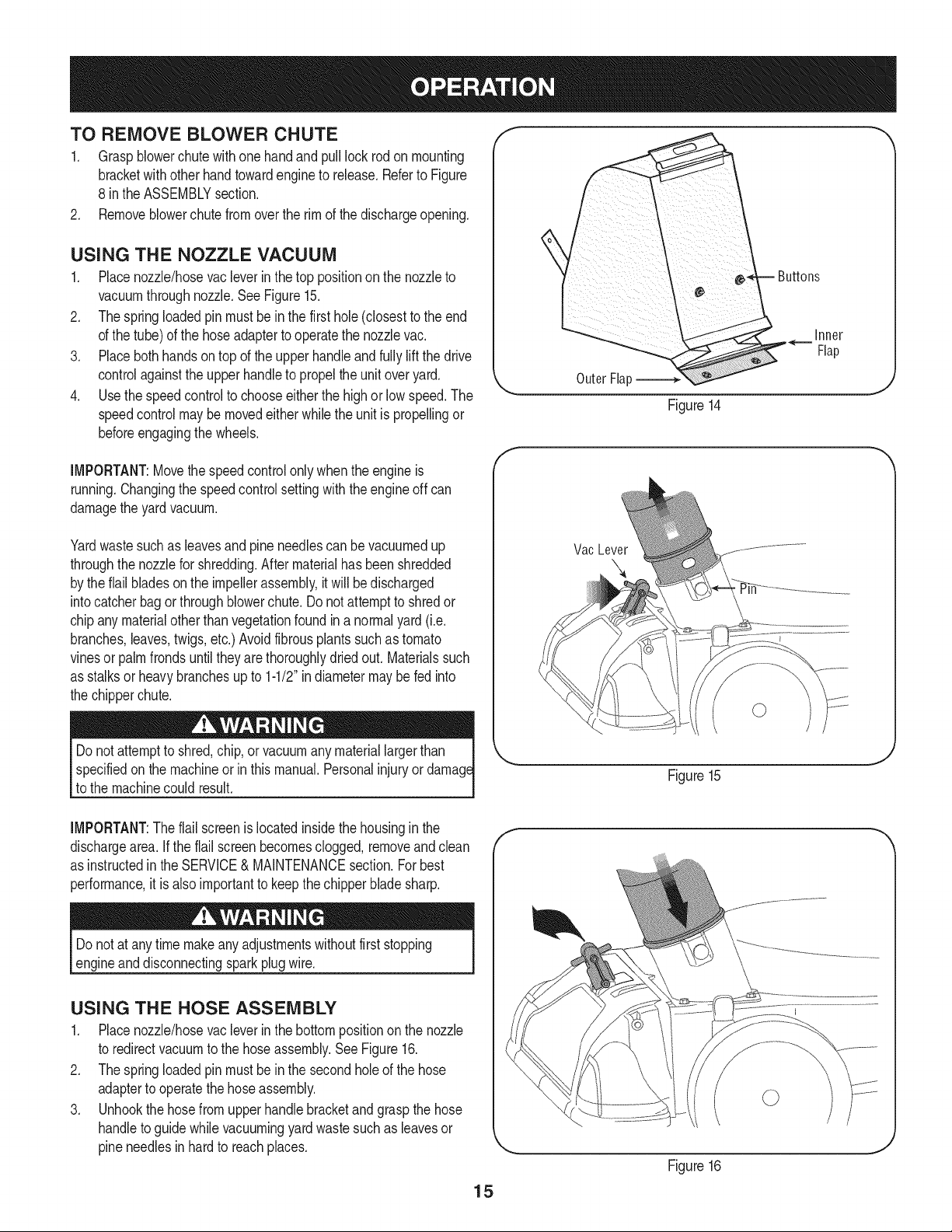
5. Movethrottlecontrolto START/RUN(Rabbit) ,_ position.See
Figure12.
6. Movethechokecontrol I'_'1 towardthe throttlecontrolto choke
the engine'scarburetor.(Awarmenginemaynot requirechoking.)
See Figure12.
7. Standingbehindthe unit,graspstarterhandleandpull ropeout
until youfeel a drag.
8. Pullthe ropewitha rapid,continuous,full arm stroke.Keepa firm
gripon the starterhandle.Letthe roperewindslowly.
9. Repeat,if necessary,untilengine starts.Whenenginestarts,
movechokecontrolgraduallyawayfromthe throttlecontrol.
10. if enginefalters,movechoke controlback towardthe throttle
controland repeatsteps7 through9.
11. ALWAYSkeepthe throttlecontrolinthe START/RUN
positionwhenoperatingthe YardVacuum.
TO STOP ENGINE
1. Movethrottlecontrolleverto slow(turtle)_ position.
Wheneverpossible,graduallyreduceenginespeedbefore
stoppingengine.
2. Movethrottlecontrol leverto STOP or OFFposition.
3. Disconnectsparkplugwireand groundit to preventaccidental
startingwhilethe equipmentis unattended.
Figure13
J
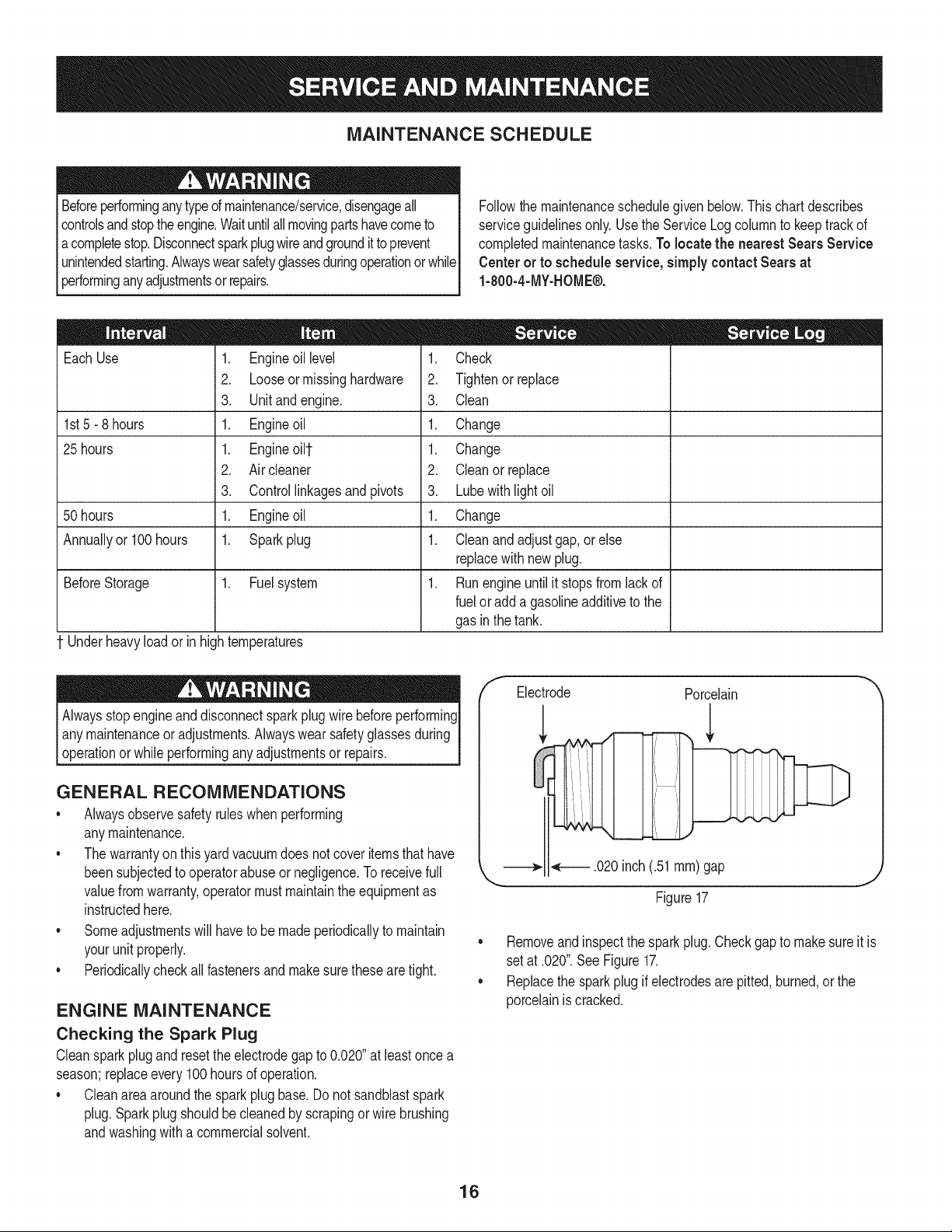
TO EMPTY BAG
1. Unhookbag strapsfromthe lowerhandle.
2. Unsnapbagclip fromthetop of lowerhandle.See Figure13.
3. Graspbag handlewith one hand and pull lock rod on mounting
bracketwith otherhandtowardengineto release.
4. Liftbagoffbackof unit.
5. Twistthe twobuttonsonthe back of the bagto unlockandempty
contents.See Figure14.Holdbag handleand bag clip while
emptyingthe contents.
6. Compressbagopeningand fold innerflap overopening.
7. Foldouter flapoverinnerflapand insertbuttonsonthe bag
throughmetaloutlets.SeeFigure14.
8. Twistthe buttonsto lock bag.Placebag backonto unitas
instructedinthe ASSEMBLYsection.
14
TO REMOVE BLOWER CHUTE
1. Graspblowerchutewithone handandpull lockrodonmounting
bracketwith otherhandtowardengineto release.Referto Figure
8 inthe ASSEMBLYsection.
2. Removeblowerchutefromoverthe rim of the dischargeopening.
USING THE NOZZLE VACUUM
1. Placenozzle/hosevacleverinthe top positionon the nozzleto
vacuumthroughnozzle.SeeFigure15.
2. Thespringloaded pin mustbe in the first hole(closestto the end
of the tube)of the hoseadapterto operatethe nozzlevac.
3. Placebothhandsontop of the upper handleand fully lift the drive
controlagainstthe upperhandleto propel the unitoveryard.
4. Use the speedcontrolto chooseeitherthe highor low speed.The
speedcontrolmaybemovedeitherwhilethe unitis propellingor
beforeengagingthewheels.
Inner
Flap
OuterFlal:
Figure14
IMPORTANT:Movethe speedcontrolonlywhenthe engineis
running.Changingthe speedcontrolsettingwiththe engineoff can
damagethe yardvacuum.
Yardwastesuchas leavesandpineneedlescan bevacuumedup
throughthe nozzlefor shredding.After materialhas beenshredded
by theflail bladesonthe impellerassembly,it will be discharged
intocatcherbagorthroughblowerchute.Do notattemptto shredor
chipany materialotherthan vegetationfoundin a normalyard(i.e.
branches,leaves,twigs,etc.)Avoidfibrousplantssuchas tomato
vinesor palmfrondsuntiltheyare thoroughlydriedout. Materialssuch
as stalksor heavybranchesup to 1-1/2"in diametermaybe fed into
the chipperchute.
Vac Lever
specifiedon the machineorin this manual.Personalinjuryor
to the machinecould result.
IMPORTANT:Theflail screenis locatedinsidethe housinginthe
dischargearea. if the flail screenbecomesclogged,removeandclean
as instructedin the SERVICE& MAINTENANCEsection.Forbest
performance,it is alsoimportantto keepthe chipperbladesharp.
Do notat any timemakeanyadjustmentswithoutfirststopping
engineanddisconnectingsparkplugwire.
USING THE HOSE ASSEMBLY
1. Placenozzle/hosevacleverinthe bottompositionon the nozzle
to redirectvacuumto the hoseassembly.SeeFigure16.
2. Thespringloaded pin mustbe in the secondholeof the hose
adapterto operatethe hoseassembly.
3. Unhookthe hosefrom upper handlebracketandgraspthe hose
handleto guidewhilevacuumingyardwastesuchas leavesor
pineneedlesin hardto reachplaces.
Figure15
15
F
Figure16
MAINTENANCE SCHEDULE
Beforeperforminganytypeofmaintenance/service,disengageall
controlsand stoptheengine.Waituntilall movingpartshavecometo
acompletestop.Disconnectsparkplugwireandgroundittoprevent
unintendedstarting.Alwayswearsafetyglassesduringoperationorwhile
performinganyadjustmentsorrepairs.
Followthe maintenanceschedulegiven below.Thischartdescribes
serviceguidelinesonly.Usethe ServiceLog columnto keeptrackof
completedmaintenancetasks.To locate the nearest Sears Service
Centeror to scheduleservice,simplycontactSearsat
1-800-4-MY-HOME®.
EachUse
1st5 - 8 hours
25 hours
50 hours
Annuallyor 100hours
BeforeStorage 1. Fuelsystem
Underheavyloador inhightemperatures
1. Engineoil level
2. Looseor missinghardware
3. Unit and engine.
1. Engineoil
1. Engineoilt
2. Air cleaner
3. Controllinkagesand pivots
1. Engineoil
1. Sparkplug
= =
1. Check
2. Tightenor replace
3. Clean
1. Change
1. Change
2. Cleanor replace
3. Lubewith light oil
1. Change
1. Cleanandadjustgap,orelse
replacewith newplug.
1. Runengineuntilit stopsfrom lack of
fuelor adda gasolineadditiveto the
gasin thetank.
Alwaysstopengineanddisconnectsparkplug wire beforeperforming
I anymaintenanceoradjustments.Alwayswear safetyglassesduring
_operationor whileperforminganyadjustmentsor repairs.
GENERAL RECOMMENDATIONS
• Alwaysobservesafetyruleswhenperforming
anymaintenance.
• Thewarrantyon thisyardvacuumdoes notcoveritemsthat have
beensubjectedto operatorabuseor negligence.To receivefull
valuefromwarranty,operatormustmaintaintheequipmentas
instructedhere.
• Someadjustmentswillhaveto be madeperiodicallyto maintain
yourunit properly.
• Periodicallycheckall fastenersand makesurethesearetight.
ENGINE MAINTENANCE
Checking the Spark Plug
Cleansparkplugandresettheelectrodegapto 0.020"at leastonce a
season;replaceevery 100hoursof operation.
• Cleanareaaroundthe sparkplugbase.Do not sandblastspark
plug.Sparkplugshouldbecleanedby scrapingorwire brushing
andwashingwitha commercialsolvent.
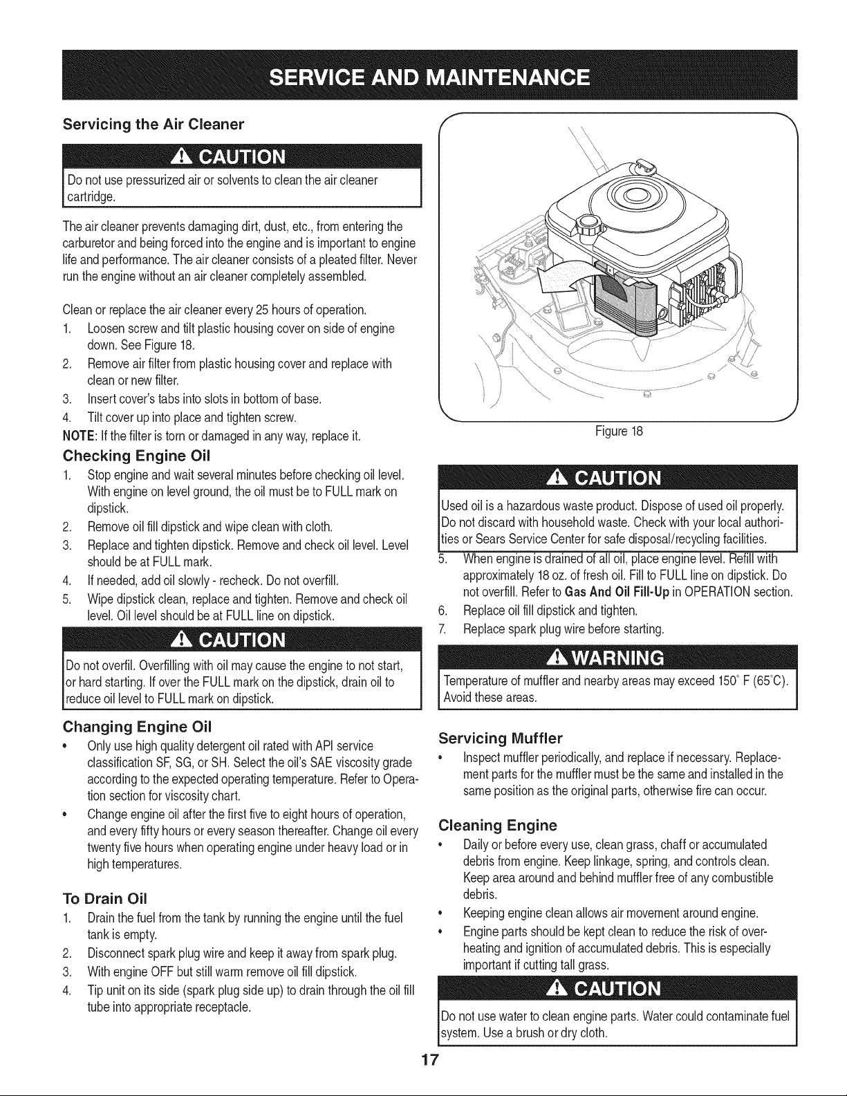
/f Electrode Porcelain
.020inch(.51ram)gap
Figure17
J
• Removeandinspectthe sparkplug.Checkgapto make sureit is
setat .020".SeeFigure17.
• Replacethe sparkplugif electrodesare pitted,burned,or the
porcelainis cracked.
16
Servicing the Air Cleaner
Do notuse pressurizedairor solventsto cleanthe aircleaner
cartridge.
Theair cleanerpreventsdamagingdirt, dust,etc.,fromenteringthe
carburetorand beingforcedintothe engineand is importantto engine
life and performance.Theair cleanerconsistsof a pleatedfilter. Never
runthe enginewithoutan aircleanercompletelyassembled.
Cleanor replacetheair cleanerevery25hoursof operation.
1. Loosenscrewandtilt plastichousingcoveron sideof engine
down.SeeFigure18.
2. Removeairfilterfromplastichousingcover and replacewith
cleanor newfilter.
3. insert cover'stabsinto slotsin bottomof base.
4. Tilt cover up into placeandtightenscrew.
NOTE:Ifthe filter is torn or damagedin anyway,replaceit.
Checking Engine Oil
1. Stopengineandwaitseveralminutesbeforecheckingoil level.
Withengineonlevelground,the oil mustbeto FULLmarkon
dipstick.
2. Removeoilfill dipstickand wipeclean withcloth.
3. Replaceandtightendipstick.Removeandcheckoil level.Level
shouldbeat FULLmark.
4. If needed,addoil slowly- recheck.Do notoverfill.
5. Wipedipstickclean, replaceandtighten.Removeand checkoil
level.Oil levelshouldbe at FULLlineondipstick.
Donotoverfil.Overfillingwithoil maycausetheengineto not start,
or hardstarting.Ifoverthe FULLmark on the dipstick,drainoil to
reduceoil levelto FULLmarkon dipstick.
f
x \
\
©
Figure18
J
Usedoil is a hazardouswasteproduct.Disposeof usedoil properly.
IDo notdiscardwithhouseholdwaste.Checkwith your localauthori-
_tiesorSearsServiceCenterfor safe disposal/recyclingfacilities.
5. Whenengineis drainedof all oil, placeenginelevel.Refillwith
approximately18oz.of fresh oil. Fillto FULLlineondipstick.Do
notoverfill.Referto Gas And Oil Fill-Up inOPERATIONsection.
6. Replaceoil fill dipstickandtighten.
7. Replacespark plugwire beforestarting.
Temperatureof mufflerandnearbyareasmay exceed150° F (65°C).
Avoidtheseareas.
Changing Engine Oil
• Onlyuse highqualitydetergentoil ratedwithAPIservice
classificationSF,SG, or SH. Select theoil's SAEviscositygrade
accordingto the expectedoperatingtemperature.Referto Opera-
tion sectionfor viscositychart.
• Changeengineoil afterthe first fiveto eighthoursof operation,
andeveryfifty hoursoreveryseasonthereafter.Changeoil every
twentyfivehourswhenoperatingengineunder heavyload or in
hightemperatures.
To Drain Oil
1. Drainthe fuelfrom the tankby runningthe engineuntil thefuel
tankis empty.
2. Disconnectsparkplugwireandkeepit away fromspark plug.
3. With engineOFF butstill warm removeoil fill dipstick.
4. Tip uniton itsside (sparkplug side up)to drain throughthe oil fill
tubeinto appropriatereceptacle.
Servicing Muffler
• inspectmufflerperiodically,andreplaceif necessary.Replace-
mentpartsfor the mufflermustbe the sameandinstalledinthe
samepositionas theoriginalparts,otherwisefirecan occur.
Cleaning Engine
• Dailyor beforeeveryuse,cleangrass,chaff or accumulated
debrisfromengine.Keeplinkage,spring,andcontrolsclean.
Keepareaaroundand behindmufflerfree of anycombustible
debris.
• Keepingenginecleanallowsair movementaroundengine.
• Engineparts shouldbe kept cleanto reducethe riskof over-
heatingand ignitionof accumulateddebris. This isespecially
importantifcuttingtall grass.
Donot usewaterto cleanengineparts.Watercouldcontaminatefuel
system.Usea brushor dry cloth.
17
Carburetor Adjustment f ..../ _,
Thecarburetoronthis engineis not useradjustable.ContactSears /
Parts& Repairforadjustment,
Engine Speed
Do not,attemptto alterthe enginespeedby tamperingwith the
engines governorlinkage.Doingsocould resultin seriouspersonal
I injuryand damageto the engine.The engineRPM hasbeen set at
thefactory.
LUBRICATION
• Wheels- Placea fewdrops of SAE30 oilon eachshoulderscrew
oncea season.
• Nozzle height adjustment levers- Lubricatenozzleheight
adjustmentleverswith lightoil.
• Locking Rod- Lubricatethe lock rodand compressionsprings
whichattachto the mountingbracket.
• Nozzle/Hose Vac Lever: Lubricatethe nozzle/hosevac leveron
topof the nozzleonce a seasonwith lightoil.
/
Figure19
CLEANING EQUIPMENT
Cleanundersideof theyardvacuumonce a seasonto preventbuild-up
of debris.Followstepsbelowfor thisjob.
1. Disconnectandgroundsparkplugwire.Emptythe fueltankby
runningengineuntiltankis dry.
2. Tipthe yard vacuumso thatit restson itsside,keepingthe
mufflersidedown.Holdyardvacuumfirmly.
3. Scrapeandcleanthe undersideof the deck and nozzlewith a
suitabletool.Donot spraywithwater.
IMPORTANT:Donot usea pressurewasherorgardenhoseto clean
yourunit.Thesemaycausedamageto bearings,orthe engine.The
useof water will resultin shortenedlife and reduceserviceability.
4. Putthe yardvacuumbackon itswheelson theground.
CLEANING THE FLAIL SCREEN
Ifthe dischargearea becomesclogged,removetheflail screenand
cleanareaas follows:
1. Stopthe engine.Makecertainthe chipper/shreddervacuumhas
cometo a completestop.
2. Beforeuncloggingthe dischargechute,disconnect and ground
the spark plugwire.
3. Removethe vacuumbagor blowerchutefromthe unitas
instructedin the OPERATIONsectionto obtainaccessto flail
screen.
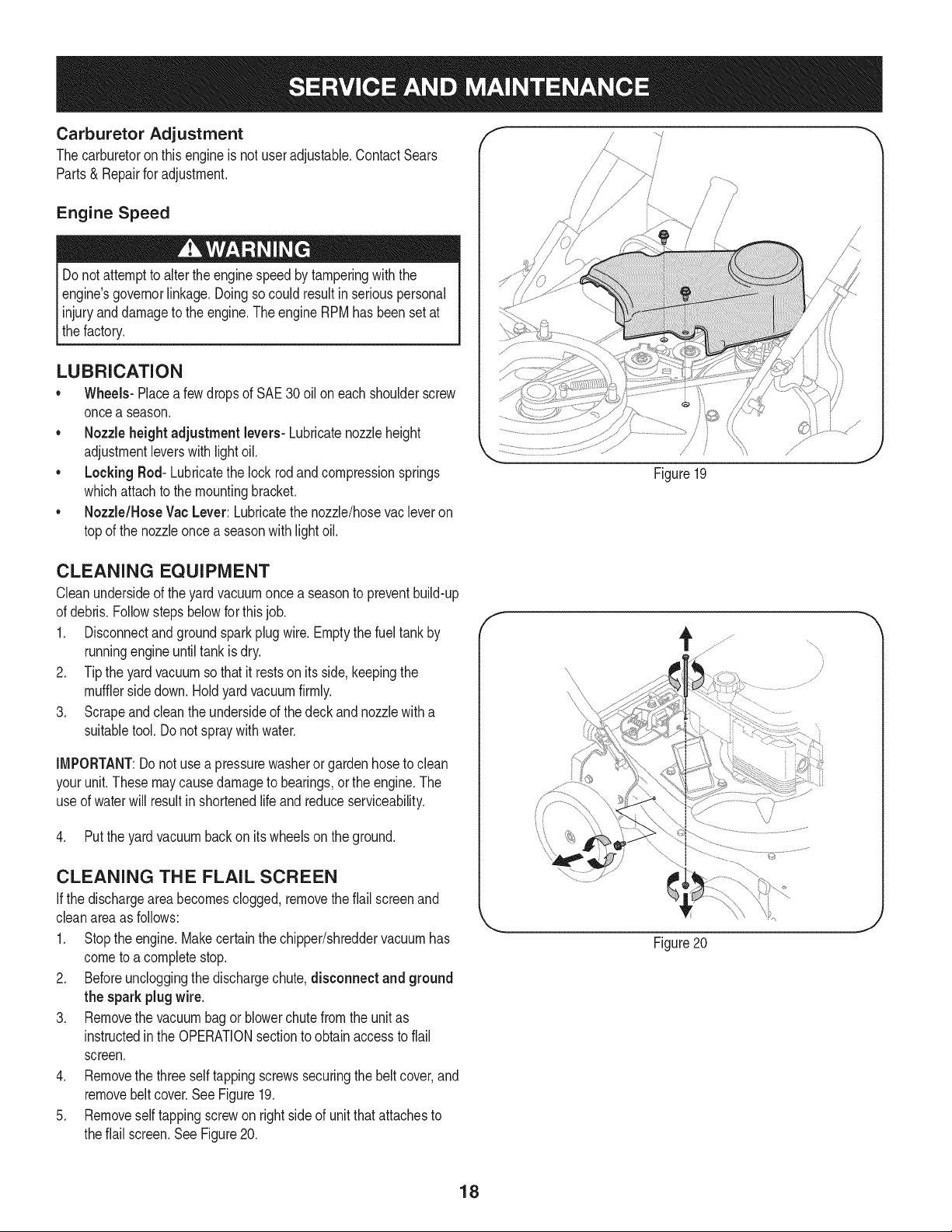
4. Removethe three self tappingscrewssecuringthebelt cover,and
removebeltcover.See Figure19.
5. Removeselftappingscrewon rightsideof unitthat attachesto
theflail screen.See Figure20.
f
/
Figure20
J
18
6. Removehexscrewontop of rearhousingnear mountingbracket
andthe flangelocknutthatsecuresflail screen.SeeFigure20.
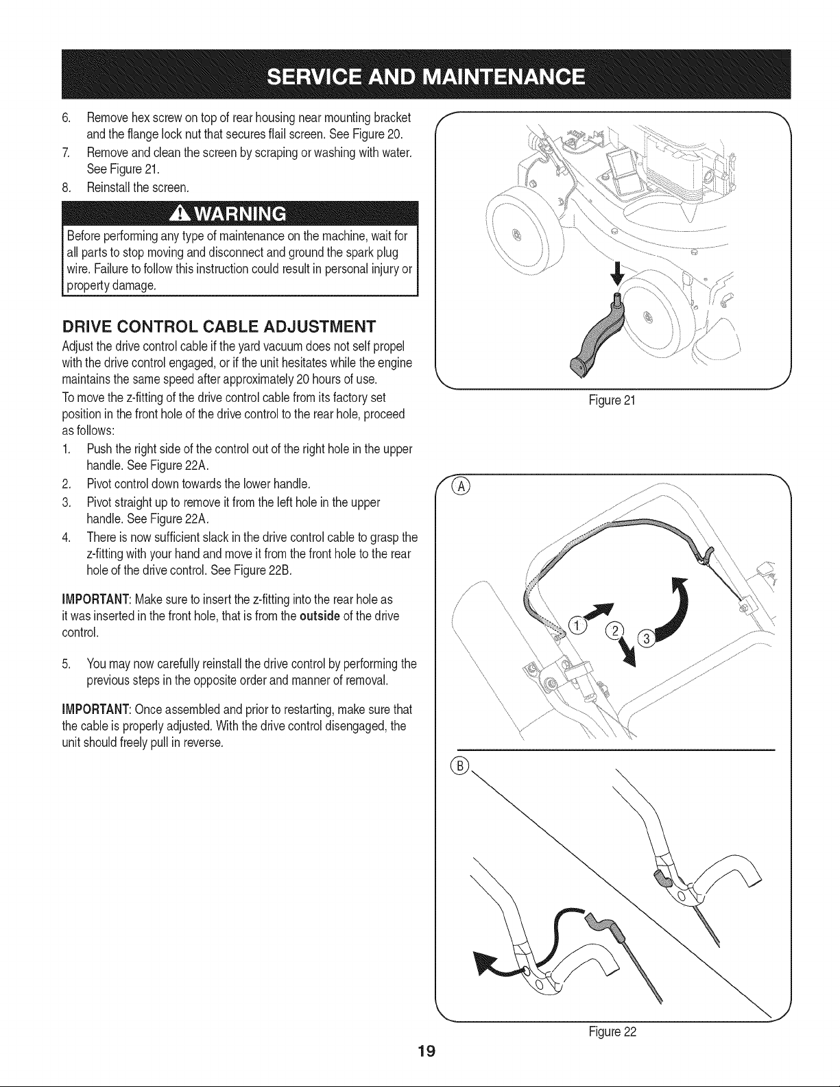
7. Removeandcleanthe screenby scrapingorwashingwithwater.
SeeFigure21.
8. Reinstallthe screen.
Beforeperforminganytype of maintenanceon the machine,waitfor
all partsto stop movingand disconnectand groundthe sparkplug
wire. Failureto followthisinstructioncould resultin personalinjuryor
propertydamage.
DRIVE CONTROL CABLE ADJUSTMENT
Adjustthe drivecontrolcableif theyard vacuumdoes not selfpropel
withthe drivecontrolengaged,orif the unithesitateswhilethe engine
maintainsthe samespeedafterapproximately20 hoursof use.
Tomovethe z-fittingof the drivecontrolcablefromitsfactoryset
positioninthe front hole of the drivecontrolto the rearhole,proceed
as follows:
1. Pushthe rightsideof thecontrol outof the rightholeinthe upper
handle.See Figure22A.
2. Pivotcontroldowntowardsthe lowerhandle.
3. Pivotstraightup to removeit fromthe left hole in the upper
handle.See Figure22A.
4. Thereis nowsufficientslackinthe drivecontrolcableto graspthe
z-fittingwithyourhandandmoveit from the frontholeto the rear
holeof the drivecontrol.See Figure22B.
IMPORTANT:Makesureto insertthe z-fittingintothe rearholeas
it was insertedin the fronthole,thatis fromthe outside of the drive
control.
5. Youmay nowcarefullyreinstallthe drivecontrolby performingthe
previoussteps in the oppositeorderandmannerof removal.
IMPORTANT:Onceassembledand priorto restarting,makesurethat
the cableis properlyadjusted.Withthe drivecontroldisengaged,the
unit shouldfreelypullin reverse.
f
\
J
Figure21
\
19
Figure22
SHARPENING OR REPLACING CHIPPER
BLADE
NOTE:Beforetippingthe unit,emptythefuel tank by runningengine
untiltankisdry,andemptythe oil reservoiras describedinTo Drain
Oil.
1. Disconnectand groundthe spark plugwire.
2. Removebagassemblyor blowerchute.
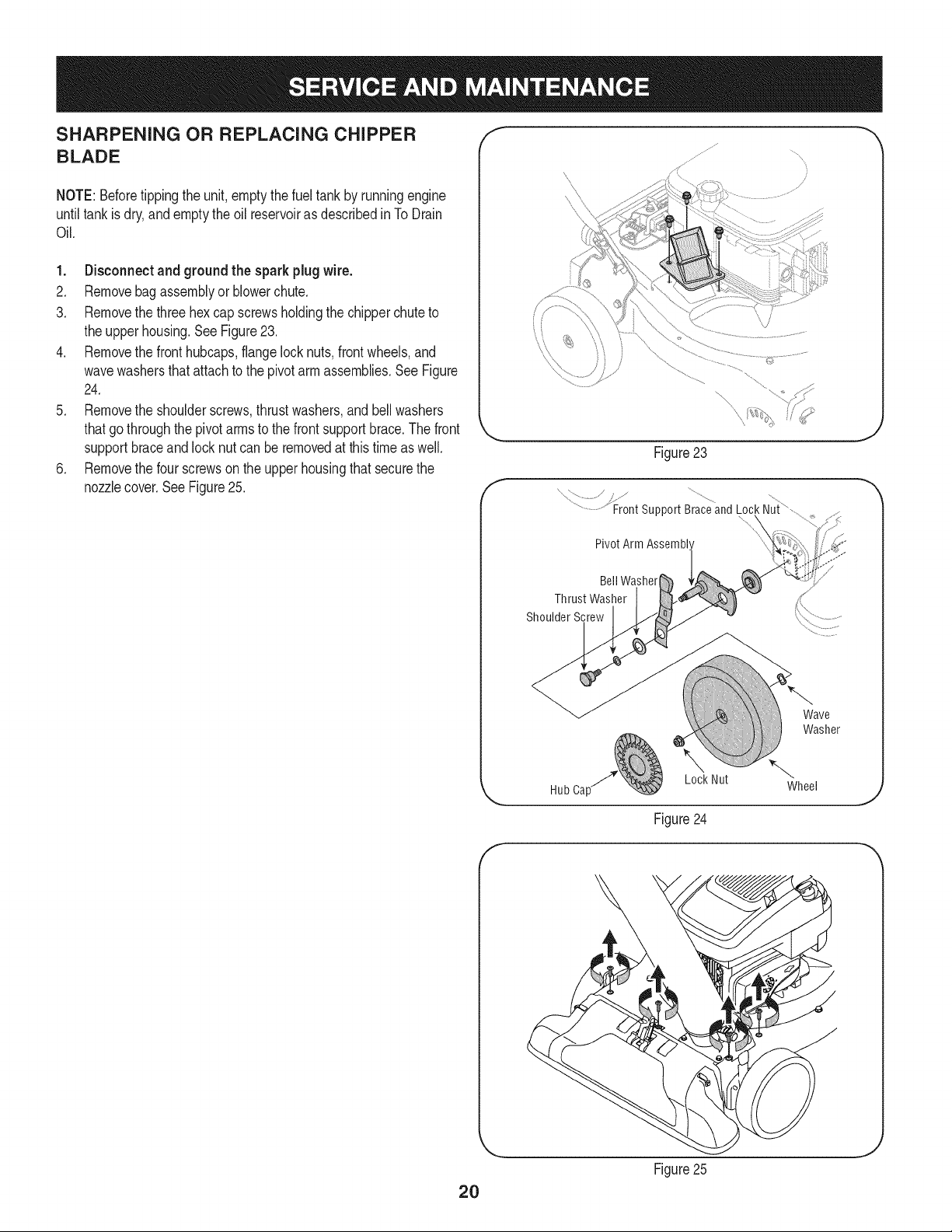
3. Removethe three hexcap screwsholdingthe chipperchuteto
the upperhousing.SeeFigure23.
4. Removethe fronthubcaps,flangelocknuts,frontwheels,and
wavewashersthat attachto the pivotarm assemblies.See Figure
24.
5. Removethe shoulderscrews,thrustwashers,andbellwashers
thatgothroughthe pivotarmsto the frontsupportbrace.The front
supportbraceandlocknut can be removedat thistimeas well.
6. Removethe four screwson the upperhousingthat securethe
nozzlecover.See Figure25.
f
Figure23
x /
..........................Front support Braceand Lock Nui,
Pivot Arm Assembl'
J
Bell Washer
Thrust Washer
Shoulder Screw
Wave
Washer
Lock Nut
Hub Ca[ Wheel
J
Figure24
f
2O
Figure25
J
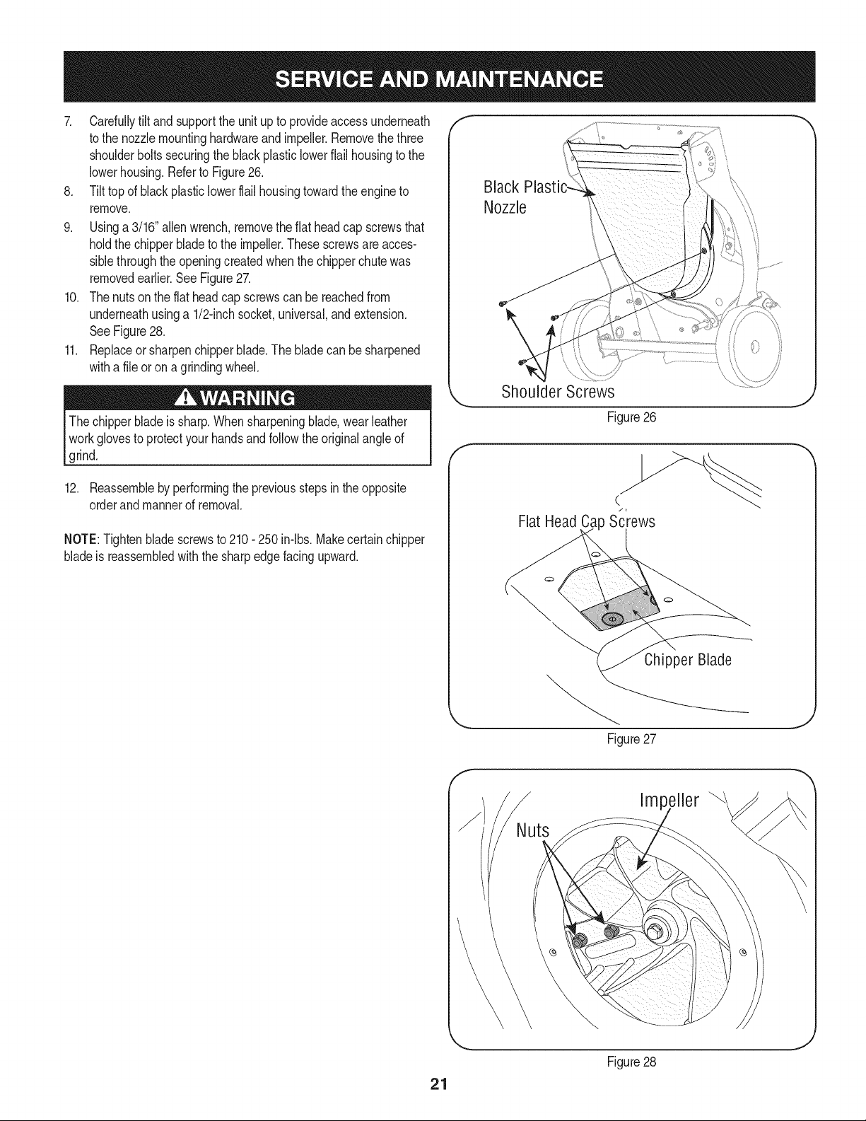
7. Carefullytilt andsupportthe unit upto provideaccessunderneath
to the nozzlemountinghardwareand impeller.Removethe three
shoulderbolts securingthe blackplasticlowerflail housingto the
lowerhousing.Referto Figure26.
8. Tilt top of black plasticlowerflail housingtowardthe engineto
remove.
9. Usinga 3/16"allenwrench,removetheflat headcap screwsthat
holdthe chipperbladeto the impeller.Thesescrewsare acces-
siblethroughtheopeningcreatedwhenthechipperchutewas
removedearlier.See Figure27.
10. Thenuts on the flat headcap screwscan bereachedfrom
underneathusinga 1/2-inchsocket,universal,andextension.
SeeFigure28.
11. Replaceor sharpenchipperblade.The bladecan be sharpened
witha fileor ona grindingwheel.
The chipperbladeis sharp.Whensharpeningblade,wear leather
workglovesto protectyourhandsandfollowthe originalangleof
grind.
12. Reassembleby performingthe previousstepsin theopposite
orderand mannerof removal.
NOTE:Tightenbladescrewsto 210- 250 in-lbs. Makecertainchipper
bladeis reassembledwith the sharpedgefacingupward.
Black
Nozzle
\
f
Shoulder Screws
Figure26
C
Flat Head Ca Screws
Chipper Blade
Figure27
J
Impeller
21
Figure28
J
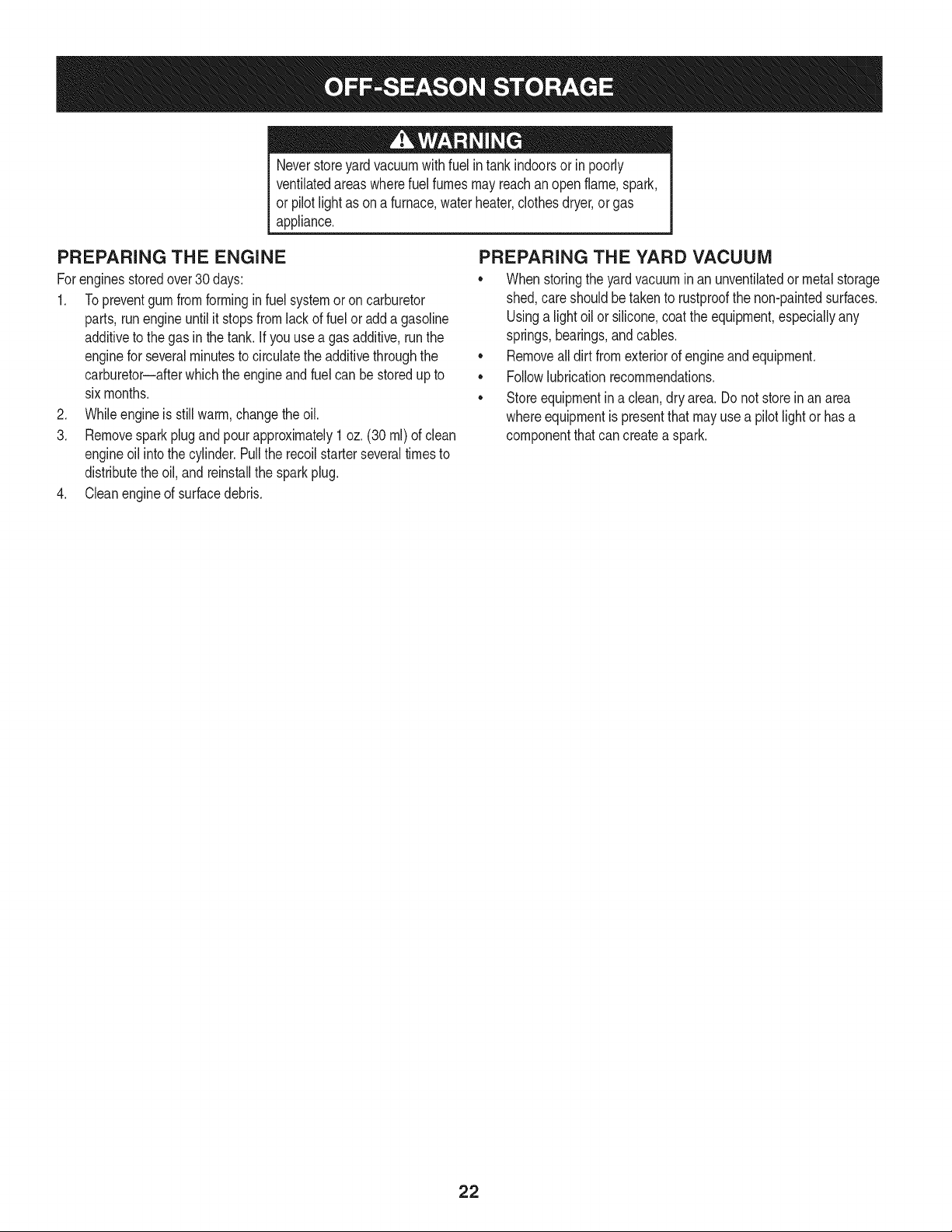
Neverstoreyardvacuumwith fuel intankindoorsor in poorly
ventilatedareaswherefuel fumesmay reachanopenflame,spark,
or pilotlight as ona furnace,waterheater,clothesdryer,or gas
appliance.
PREPARING THE ENGINE
Forenginesstoredover30 days:
1. To preventgumfrom formingin fuel systemor on carburetor
parts, run engineuntilit stopsfromlackof fuelor add a gasoline
additiveto the gas inthe tank. Ifyou usea gas additive,runthe
enginefor severalminutesto circulatethe additivethroughthe
carburetor--afterwhichthe engineandfuel can bestoredup to
six months.
2. Whileengineis still warm,changethe oil.
3. Removespark plugand pourapproximately1 oz. (30 rnl) of clean
engineoil intothe cylinder.Pullthe recoilstarterseveraltimesto
distributethe oil, and reinstallthe sparkplug.
4. Cleanengineof surfacedebris.
PREPARING THE YARD VACUUM
• Whenstoringthe yardvacuumin an unventilatedor metalstorage
shed,careshouldbetakento rustproofthe non-paintedsurfaces.
Usinga lightoil orsilicone,coatthe equipment,especiallyany
springs,bearings,andcables.
• Removealldirt fromexteriorof engineand equipment.
• Followlubricationrecommendations.
• Storeequipmentin a clean,dry area.Do not storein anarea
whereequipmentis presentthatmayusea pilot lightor hasa
componentthatcan createa spark.
22
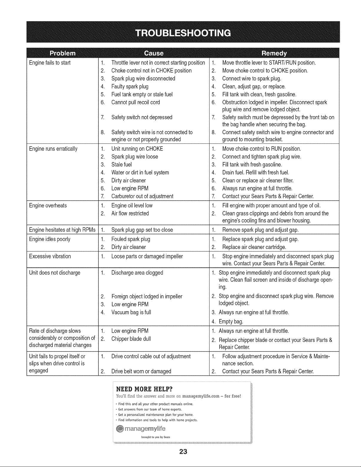
Enginefailsto start
Enginerunserratically
1. Throttlelevernot in correctstartingposition
2. Chokecontrolnot inCHOKEposition
3. Sparkplugwire disconnected
4. Faultysparkplug
5. Fueltank emptyorstalefuel
6. Cannotpull recoilcord
7. Safetyswitchnotdepressed
Engineoverheats
Enginehesitatesat high RPMs 1. Sparkpluggap settoo close
Engineidlespoorly 1. Fouledsparkplug
2. Dirtyair cleaner
Excessivevibration 1. Loosepartsor damagedimpeller
Unitdoesnot discharge 1. Dischargeareaclogged
Rated dischargeslows
considerablyor compositionof
dischargedmaterialchanges
Unitfailsto propel itselfor
slipswhendrivecontrolis
engaged
8. Safetyswitchwire is not connectedto
engineor notproperlygrounded
1. Unit runningon CHOKE
2. Sparkplugwire loose
3. Stalefuel
4. Wateror dirt in fuel system
5. Dirtyair cleaner
6. Lowengine RPM
7. Carburetorout of adjustment
1. Engineoil levellow
2. Air flow restricted
2. Foreignobjectlodgedin impeller
3. Lowengine RPM
4. Vacuumbagis full
1. Lowengine RPM
2. Chipperbladedull
1. Drivecontrolcableout of adjustment
2. Drivebelt wornordamaged
1. Movethrottleleverto START/RUNposition.
2. Movechokecontrolto CHOKEposition.
3. Connectwire to spark plug.
4. Clean,adjustgap,or replace.
5. Filltank with clean,fresh gasoline.
6. Obstructionlodgedin impeller.Disconnectspark
plugwire and removelodgedobject.
7. Safetyswitchmustbedepressedby thefront tab on
the bag handlewhen securingthe bag.
8. Connectsafetyswitchwireto engineconnectorand
groundto mountingbracket.
1. Movechokecontrolto RUNposition.
2. Connectandtightensparkplugwire.
3. Filltank with fresh gasoline.
4. Drainfuel. Refillwith freshfuel.
5. Cleanor replaceair cleanerfilter.
6. Alwaysrunengineat full throttle.
7. ContactyourSearsParts& RepairCenter.
1. Fillenginewith properamountand type of oil.
2. Cleangrassclippingsanddebrisfromaroundthe
engine'scoolingfinsandblowerhousing.
1. Removesparkplugandadjustgap.
1. Replacespark plug and adjustgap.
2. Replaceair cleanercartridge.
1. Stopengineimmediatelyand disconnectsparkplug
wire.ContactyourSearsParts& RepairCenter.
1. Stopengineimmediatelyand disconnectsparkplug
wire.Cleanflail screenand insideof dischargeopen-
ing.
2. Stopengineand disconnectspark plugwire. Remove
lodgedobject.
3. Alwaysrunengineat full throttle.
4. Emptybag.
1. Alwaysrunengineat full throttle.
2. Replacechipperbladeor contactyourSearsParts &
RepairCenter.
1. Followadjustmentprocedurein Service& Mainte-
nancesection.
2. ContactyourSearsParts& RepairCenter.
Find this and al! your other product manuals online.
Get answers from our team of home experts.
Get a personalized maintenance plan for your home.
Find information and tools to help with home projects.
23
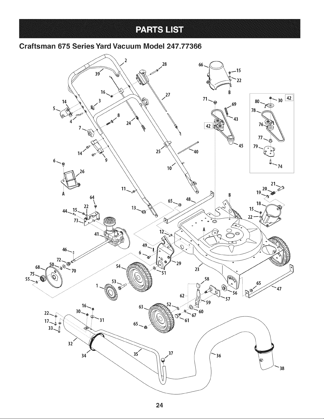
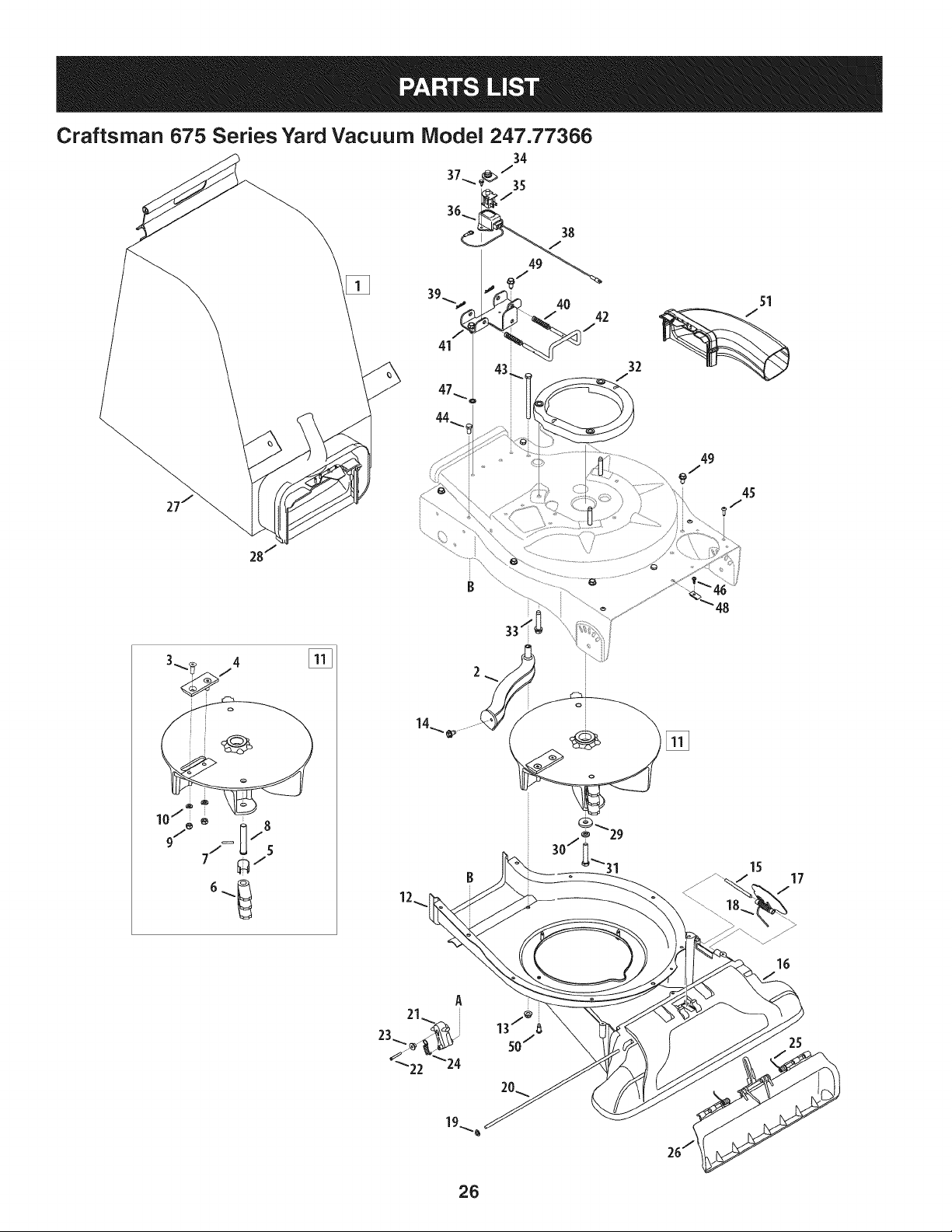
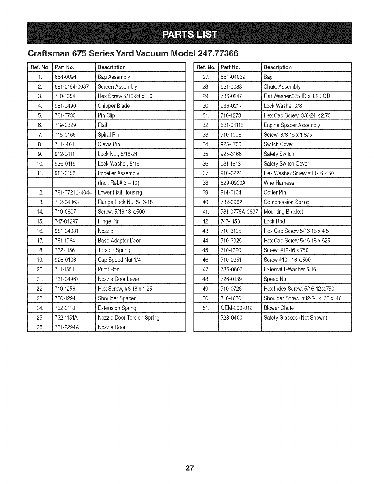
Craftsman 675 Series Yard Vacuum Model 247.77366
14
A
39
64
\
@
2
/
24
28
27
/
25
./
I0
A
53
/
23
58
59
57
32
34
35
37
24
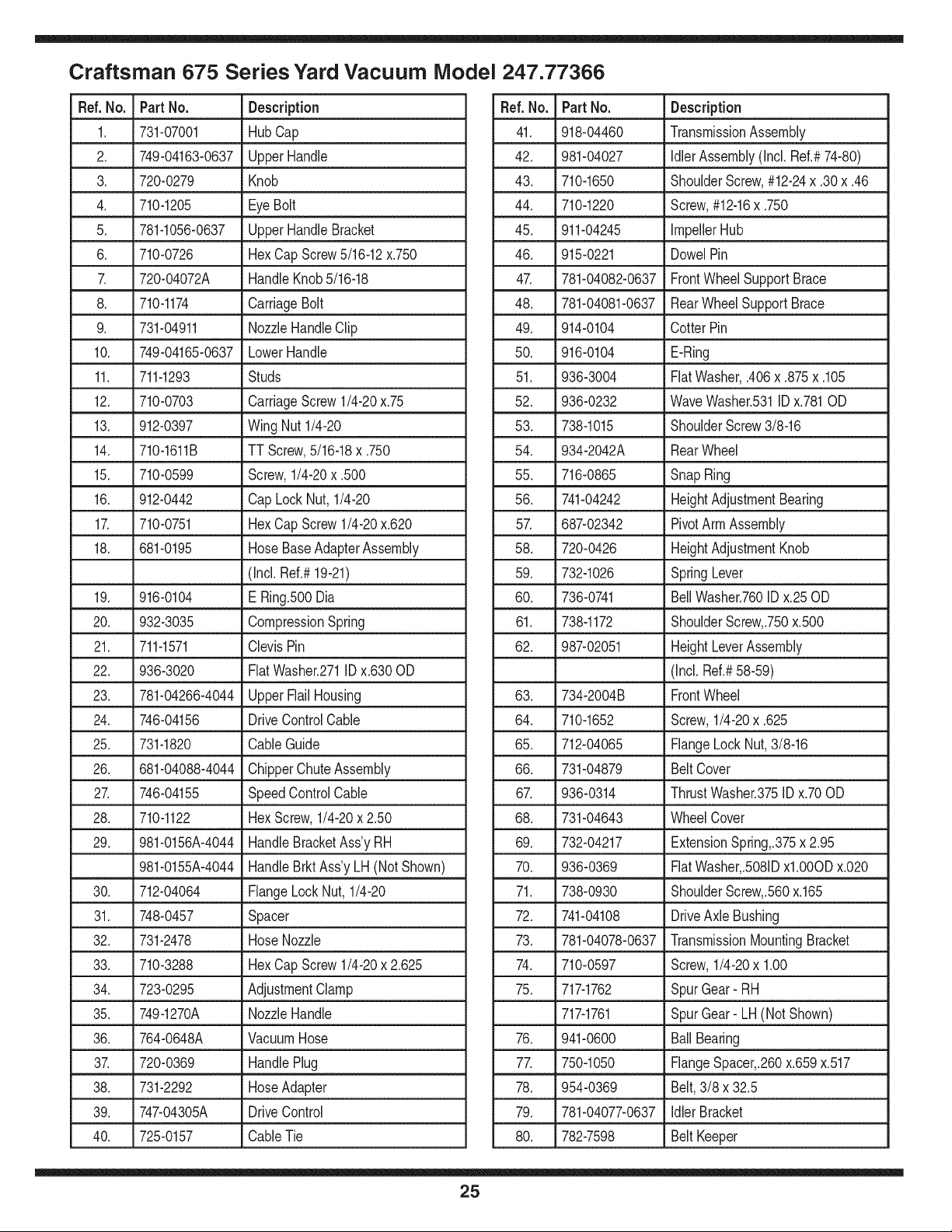
Craftsman 675 Series Yard Vacuum Model 247.77366
Ref. No. Part No. Description
1. 731-07001 HubCap
2. 749-04163-0637 UpperHandle
3. 720-0279 Knob
4. 710-1205 EyeBolt
5. 781-1056-0637 UpperHandleBracket
6. 710-0726 HexCap Screw5/16-12x.750
7. 720-04072A HandleKnob5/16-18
8. 710-1174 CarriageBolt
9. 731-04911 NozzleHandleClip
10. 749-04165-0637 LowerHandle
11. 711-1293 Studs
12. 710-0703 CarriageScrew 1/4-20x.75
13. 912-0397 Wing Nut 1/4-20
14. 710-1611B TT Screw,5/16-18x .750
15. 710-0599 Screw,1/4-20x .500
16. 912-0442 Cap Lock Nut, 1/4-20
17. 710-0751 HexCap Screw1/4-20x.620
18. 681-0195 HoseBaseAdapterAssembly
(Incl. Ref.#19-21)
19. 916-0104 E Ring.500Dia
20. 932-3035 CompressionSpring
21. 711-1571 ClevisPin
22. 936-3020 FiatWasher.271IDx.630OD
23. 781-04266-4044 UpperFlailHousing
24. 746-04156 DriveControlCable
25. 731-1820 CableGuide
26. 681-04088-4044 ChipperChuteAssembly
27. 746-04155 SpeedControlCable
28. 710-1122 HexScrew,1/4-20x 2.50
29. 981-0156A-4044 HandleBracketAss'yRH
981-0155A-4044 HandleBrkt Ass'yLH (Not Shown)
30. 712-04064 FlangeLock Nut, 1/4-20
31. 748-0457 Spacer
32. 731-2478 HoseNozzle
33. 710-3288 HexCap Screw1/4-20x 2.625
34. 723-0295 AdjustmentClamp
35. 749-1270A NozzleHandle
36. 764-0648A VacuumHose
37. 720-0369 HandlePlug
38. 731-2292 HoseAdapter
39. 747-04305A DriveControl
40. 725-0157 CableTie
Ref.No. Part No. Description
41. 918-04460 TransmissionAssembly
42. 981-04027 IdlerAssembly(Incl. Ref.#74-80)
43. 710-1650 ShoulderScrew,#12-24x .30x .46
44. 710-1220 Screw,#12-16x .750
45. 911-04245 ImpellerHub
46. 915-0221 DowelPin
47. 781-04082-0637 FrontWheelSupportBrace
48. 781-04081-0637 RearWheelSupportBrace
49. 914-0104 CotterPin
50. 916-0104 E-Ring
51. 936-3004 FiatWasher,.406x .875x .105
52. 936-0232 WaveWasher.531IDx.781OD
53. 738-1015 ShoulderScrew3/8-16
54. 934-2042A RearWheel
55. 716-0865 SnapRing
56. 741-04242 HeightAdjustmentBearing
57. 687-02342 PivotArmAssembly
58. 720-0426 HeightAdjustmentKnob
59. 732-1026 SpringLever
60. 736-0741 BellWasher.760IDx.25OD
61. 738-1172 ShoulderScrew,.750x.500
62. 987-02051 HeightLeverAssembly
(Incl. Ref.#58-59)
63. 734-2004B FrontWheel
64. 710-1652 Screw,1/4-20x .625
65. 712-04065 FlangeLockNut,3/8-16
66. 731-04879 Belt Cover
67. 936-0314 ThrustWasher.375IDx.70OD
68. 731-04643 WheelCover
69. 732-04217 ExtensionSpring,.375x 2.95
70. 936-0369 FiatWasher,.5081Dxl.0OODx.020
71. 738-0930 ShoulderScrew,.560x.165
72. 741-04108 DriveAxle Bushing
73. 781-04078-0637 TransmissionMountingBracket
74. 710-0597 Screw,1/4-20x 1.00
75. 717-1762 SpurGear- RH
717-1761 SpurGear- LH (NotShown)
76. 941-0600 BallBearing
77. 750-1050 FlangeSpacer,.260x.659x.517
78. 954-0369 Belt,3/8 x 32.5
79. 781-04077-0637 Idler Bracket
80. 782-7598 Belt Keeper
25
Craftsman 675 Series Yard Vacuum Model 247.77366
45
2
o
48
15
17
7
16
25
26
Craftsman 675 Series Yard Vacuum iVlodel 247.77366
Ref. No. Part No. Description
1. 664-0094 BagAssembly
2. 681-0154-0637 ScreenAssembly
3. 710-1054 HexScrew5/16-24x 1.0
4. 981-0490 ChipperBlade
5. 781-0735 PinClip
6. 719-0329 Flail
7. 715-0166 SpiralPin
8. 711-1401 ClevisPin
9. 912-0411 Lock Nut,5/16-24
10. 936-0119 LockWasher,5/16
11. 981-0152 ImpellerAssembly
(Incl. Ref.#3 - 10)
12. 781-0721B-4044 LowerFlailHousing
13. 712-04063 FlangeLockNut5/16-18
14. 710-0607 Screw,5/16-18x.500
15. 747-04297 HingePin
16. 981-04031 Nozzle
17. 781-1064 BaseAdapterDoor
18. 732-1156 TorsionSpring
19. 926-0106 CapSpeedNut1/4
20. 711-1551 PivotRod
21. 731-04967 NozzleDoorLever
22. 710-1256 HexScrew,#8-18x 1.25
23. 750-1294 ShoulderSpacer
24. 732-3118 ExtensionSpring
25. 732-1151A NozzleDoorTorsionSpring
26. 731-2294A NozzleDoor
Ref.No. Part No. Description
27. 664-04039 Bag
28. 631-0083 ChuteAssembly
29. 736-0247 FiatWasher.375IDx 1.25OD
30. 936-0217 LockWasher3/8
31. 710-1273 HexCap Screw,3/8-24 x 2.75
32. 631-04118 EngineSpacerAssembly
33. 710-1008 Screw,3/8-16x 1.875
34. 925-1700 SwitchCover
35. 925-3166 SafetySwitch
36. 931-1613 SafetySwitchCover
37. 910-0224 HexWasherScrew#10-16x.50
38. 629-0920A Wire Harness
39. 914-0104 CotterPin
40. 732-0962 CompressionSpring
41. 781-0778A-0637 MountingBracket
42. 747-1153 LockRod
43. 710-3195 HexCap Screw5/16-18x 4.5
44. 710-3025 HexCap Screw5/16-18x.625
45. 710-1220 Screw,#12-16x.750
46. 710-0351 Screw#10- 16x.500
47. 736-0607 ExternalbWasher5/16
48. 726-0139 SpeedNut
49. 710-0726 Hex indexScrew,5/16-12x.750
50. 710-1650 ShoulderScrew,#12-24x .30x .46
51. 0EM-290-012 BlowerChute
-- 723-0400 SafetyGlasses(Not Shown)
27
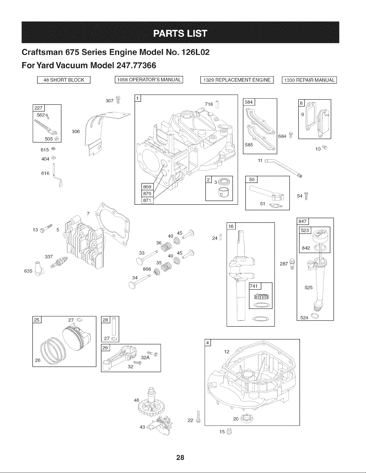
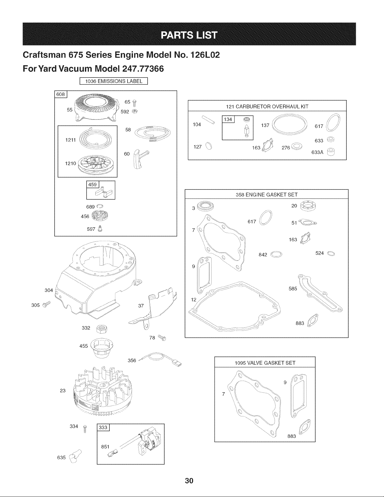
Craftsman 675 Series Engine Model No. 126L02
For Yard Vacuum Model 247.77366
[ 48 SHORT BLOCK ] 11058 OPERATOR'S MANUAL I I 1329 REPLACEMENT ENGINE I 11330REPAIRMANUALI
26
307 }_
32
43
718 _i
684 ?
24
287
12
20 _%_J
15 _-;j
10_)
525i
524 (q_
28
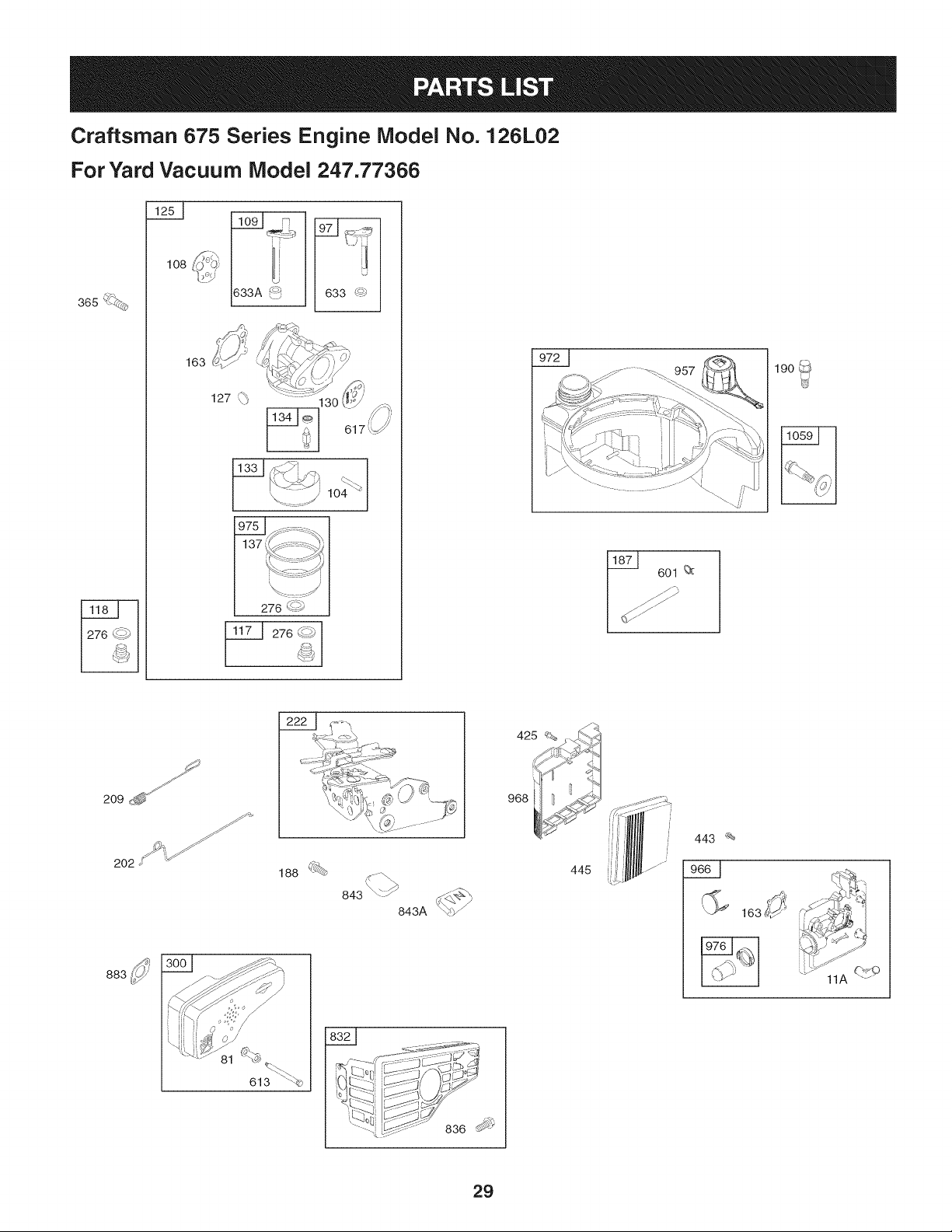
Craftsman 675 Series Engine iVlodel No. 126L02
For Yard Vacuum iVlodel 247.77366
108
163
_JL
276 (<_
_ 276 _- _)
190
J
209 _'fJ" J_
202 _ ::"_ _/'yj_
188 <_#_
843\-:_ _,
843A '
425 _%
968
443 _
(_ 163i
613 \<_
29
Craftsman 675 Series Engine Model No. 126L02
For Yard Vacuum Model 247.77366
I 1036 EMISSIONS LABEL I
304
305 _
65 _
55 592 -_(_,
1211
1210
S
689 ....
456
597
58
6O
104 _
127 ',_
121 CARBURETOR OVERHAUL KIT
358 ENGINE GASKET SET
3 _:::_ 20
7
51 _ "_'_,_
163 ¢2
524 _ _,
883 i!p_
1095 VALVE GASKET SET
/
334
/_ 851 _/\
',\ ?
883
30
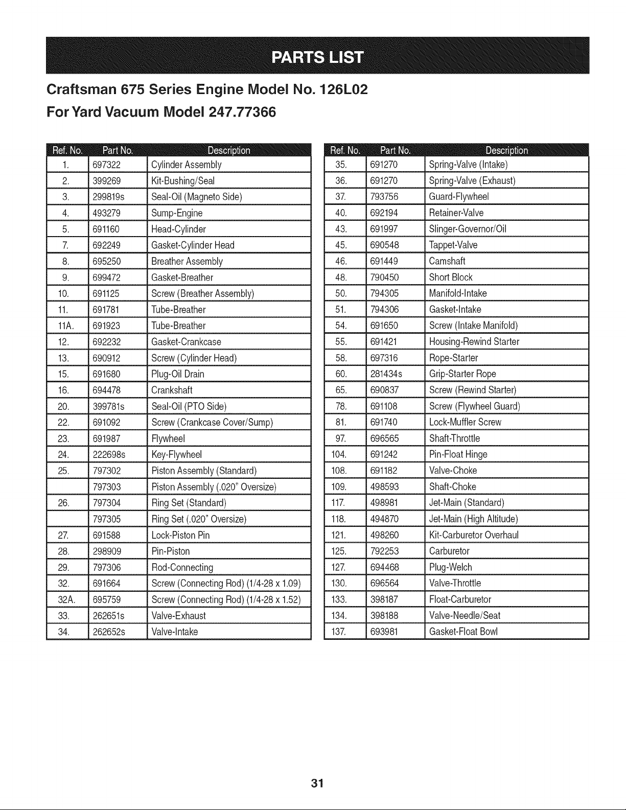
Craftsman 675 Series Engine Model No. 126L02
For Yard Vacuum iVlodel 247.77366
D = " O
697322 CylinderAssembly
2. 399269 Kit-Bushing/Seal
3. 299819s Seal-Oil(MagnetoSide)
4. 493279 Sump-Engine
5. 691160 Head-Cylinder
7. 692249 Gasket-CylinderHead
8. 695250 BreatherAssembly
9. 699472 Gasket-Breather
10. 691125 Screw(BreatherAssembly)
11. 691781 Tube-Breather
11A. 691923 Tube-Breather
12. 692232 Gasket-Crankcase
13. 690912 Screw(CylinderHead)
15. 691680 Plug-OilDrain
16. 694478
20. 399781s
22. 691092
23. 691987
24. 222698s
25. 797302
797303
26. 797304
797305
2Z 691588
28. 298909
29. 797306
32. 691664
32A. 695759
33. 262651s
34. 262652s
Crankshaft
Seal-Oil(PTOSide)
Screw(CrankcaseCover/Sump)
Flywheel
Key-Flywheel
PistonAssembly(Standard)
PistonAssembly(.020"Oversize)
RingSet (Standard)
RingSet (.020"Oversize)
Lock-PistonPin
Pin-Piston
Rod-Connecting
Screw(ConnectingRod)(1/4-28x 1.09)
Screw(ConnectingRod)(1/4-28x 1.52)
Valve-Exhaust
Valve-Intake
D = I! II
691270 Spring-Valve(Intake)
36. 691270 Spring-Valve(Exhaust)
37. 793756 Guard-Flywheel
40. 692194 Retainer-Valve
43. 691997 Slinger-Governor/Oil
45. 690548 Tappet-Valve
46. 691449 Camshaft
48. 790450 Short Block
50. 794305 Manifold-Intake
51. 794306 Gasket-Intake
54. 691650 Screw(IntakeManifold)
55. 691421 Housing-RewindStarter
58. 697316 Rope-Starter
60. 281434s Grip-StarterRope
65. 690837 Screw(RewindStarter)
78. 691108 Screw(FlywheelGuard)
81. 691740 Lock-MufflerScrew
97. 696565 Shaft-Throttle
104. 691242 Pin-FloatHinge
108. 691182 Valve-Choke
109. 498593 Shaft-Choke
117. 498981 Jet-Main(Standard)
118. 494870 Jet-Main(HighAltitude)
121. 498260 Kit-CarburetorOverhaul
125. 792253 Carburetor
127. 694468 Plug-Welch
130. 696564 Valve-Throttle
133. 398187 Float-Carburetor
134. 398188 Valve-Needle/Seat
137. 693981 Gasket-FloatBowl
31
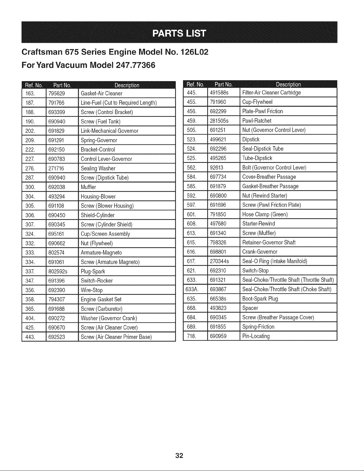
Craftsman 675 Series Engine Model No. 126L02
For Yard Vacuum iVlodel 247.77366
D = O 0
795629 Gasket-AirCleaner
187. 791766 Line-Fuel(Cutto RequiredLength)
188. 693399 Screw(ControlBracket)
190. 690940 Screw(FuelTank)
202. 691829 Link-MechanicalGovernor
209. 691291 Spring-Governor
222. 692150 Bracket-Control
227. 690783 ControlLever-Governor
276. 271716 SealingWasher
287. 690940 Screw(DipstickTube)
300. 692038 Muffler
304. 493294 Housing-Blower
305. 691108 Screw(BlowerHousing)
306. 690450 Shield-Cylinder
307. 690345 Screw(CylinderShield)
324. 695161 Cup/ScreenAssembly
332. 690662 Nut(Flywheel)
333. 802574 Armature-Magneto
334. 691061 Screw(ArmatureMagneto)
337. 802592s Plug-Spark
347. 691396 Switch-Rocker
356. 692390 Wire-Stop
358. 794307 EngineGasketSet
365. 691688 Screw(Carburetor)
404. 690272 Washer(GovernorCrank)
425. 690670 Screw(AirCleanerCover)
443. 692523 Screw(AirCleanerPrimerBase)
D = B
491588s Filter-AirCleanerCartridge
455. 791960 Cup-Flywheel
456. 692299 Plate-PawlFriction
459. 281505s PawI-Ratchet
505. 691251 Nut(GovernorControlLever)
523. 499621 Dipstick
524. 692296 Seal-DipstickTube
525. 495265 Tube-Dipstick
562. 92613 Bolt(GovernorControlLever)
584. 697734 Cover-BreatherPassage
585. 691879 Gasket-BreatherPassage
592. 690800 Nut(RewindStarter)
597. 691696 Screw(Pawl FrictionPlate)
601. 791850 HoseClamp(Green)
608. 497680 Starter-Rewind
613. 691340 Screw(Muffler)
615. 798326 Retainer-GovernorShaft
616. 698801 Crank-Governor
617. 270344s
621. 692310
633. 691321
633A. 693867
635. 66538s
668. 493823
684. 690345
689. 691855
SeaI-ORing(IntakeManifold)
Switch-Stop
Seal-Choke/ThrottleShaft(ThrottleShaft)
Seal-Choke/ThrottleShaft(ChokeShaft)
Boot-SparkPlug
Spacer
Screw(BreatherPassageCover)
Spring-Friction
718. 690959 Pin-Locating
32
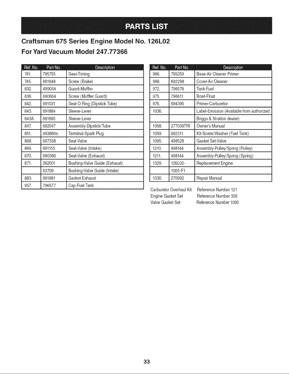
Craftsman 675 Series Engine Model No. 126L02
For Yard Vacuum iVlodel 247.77366
m = O O
795755 Gear-Timing
745. 691648 Screw(Brake)
832. 499034 Guard-Muffler
836. 690664 Screw(MufflerGuard)
842. 691031 SeaI-ORing(DipstickTube)
843. 691884 Sleeve-Lever
843A. 691895 Sleeve-Lever
847. 692047 Assembly-Dipstick/Tube
851. 493880s Terminal-SparkPlug
868. 697338 Seal-Valve
869. 691155 Seat-Valve(Intake)
870. 690380 Seat-Valve(Exhaust)
871. 262001 Bushing-ValveGuide(Exhaust)
63709 Bushing-ValveGuide(Intake)
883. 691881 Gasket-Exhaust
957. 796577 Cap-FuelTank
D = O
795259 Base-AirCleanerPrimer
968. 692298 Cover-AirCleaner
972. 796578 Tank-Fuel
975. 796611 Bowl-Float
976. 694395 Primer-Carburetor
1036. Label-Emission(Availablefromauthorized
Briggs& Strattondealer)
1058. 277039TRI Owner'sManual
1059. 692311 Kit-Screw/Washer(FuelTank)
1095. 498528 GasketSet-Valve
1210. 498144 Assembly-Pulley/Spring(Pulley)
1211. 498144 Assembly-Pulley/Spring(Spring)
1329. 126L02- ReplacementEngine
1005-F1
1330. 270962 RepairManual
CarburetorOverhaulKit ReferenceNumber121
EngineGasketSet ReferenceNumber358
ValveGasketSet ReferenceNumber1095
33
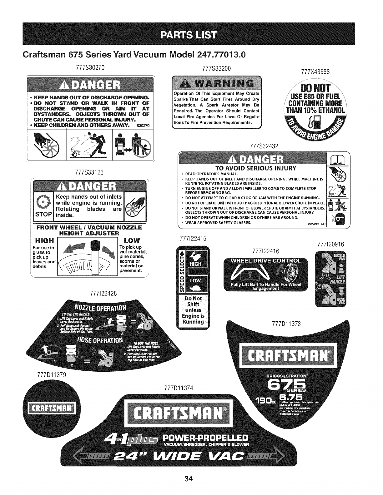
Craftsman 675 Series Yard Vacuum iVlodel 247.77013.0
777S30270 777S33200
= KEEP HANDS OUT OF D|SCHARGE OPEN|NO=
= DO NOT STAND OR WALK iN FRONT OF
DISCHARGE OPENING OR AiM iT AT
BYSTANDERS= OBJECTS THROWN OUT OF
CHUTE CAN CAUSE PERSONAL iNJURY=
• KEEP CHILDREN AND OTHERS AWAY= $30270
_' jJJJ__l
777S33123
Keep hands out of inlets
while engine is running,
Rotating blades are
inside.
FRONT WHEEL / VACUUM NOZZLE
HEIGHT ADJUSTER
LOW
To pick up
wet material,
pine cones,
acorns or
I materiaJ on
J pavement,
777122428
I Operation Of This Equipment May Create
Sparks That Can Start Fires Around Dry
Vegetation, A Spark Arrestor May Be
Required. The Operator Should Contact
Local Fire Agencies For Laws Or Regula=
t_ion Requ'_ements.
777S32432
777X43688
..................DO ............................
USEE85 ORFUEL..............
CONTAiNiNGMORE
THAN10% ETHAHOL
TO AVOID SERIOUS iNJURY
• READ OPERATOR'S MANUAL,
• KEEP HANDS OUT OF iNLET AND DISCHARGE OPENINGS WHILE MACHINE iS
RUNNING. ROTATING BLADES ARE iNSiDE.
• TURN ENGINE OFF AND ALLOW iMPELLER TO COME TO COMPLETE STOP
BEFORE REMOVING BAG.
• DO NOT ATTEMPT TO CLEAR A CLOG OR JAM WiTH THE ENGINE RUNNING.
" DO NOT OPERATE UNiTWiTHOUT BAG OR OPTIONAL BLOWER CHUTE iN PLACE.
• DO NOT STAND OR WALK IN FRONT OF BLOWER CHUTE OR AiM iT AT BYSTANDERS.
OBJECTS THROWN OUT OF DISCHARGE CAN CAUSE PERSONAL iNJURY.
• DO NOT OPERATE WHEN CHILDREN OR OTHERS ARE AROUND.
• WEAR APPROVED SAFETY GLASSES.
$32432 AC
777i22415
777122416
777Dl1373
777120916
777Dl1379
777Dl1374
34

35
(Thispageapplicablein the U.S.A.and Canadaonly.)
Sears Brands Management Corporation (Sears), the California Air Resources Board (CARD)
and the United States Environmental Protection Agency (U.S. EPA)
Emission Control System Warranty Statement (Owner's Defect Warranty Rights and Obligations)
EMISSIONCONTROLWARRANTYCOVERAGEISAPPLICABLETOCERTI-
FIEDENGINESPURCHASEDIN CALIFORNIAIN 1995ANDTHEREAF-
TER,WHICHARE USED INCALIFORNIA,ANDTO CERTIFIEDMODEL
California and United States Emission
The CaliforniaAir ResourcesBoard(CARD),U.S.EPAand Searsare pleased
to explainthe EmissionControlSystemWarrantyon your modelyear2000and
latersmalloff-roadengine(SORE).InCalifornia,newsmall off-roadengines
mustbe designed,builtand equippedto meettheState'sstringentanti-smog
standards.Elsewherein theUnitedStates,newnon-road,spark-ignition
enginescertifiedfor modelyear 1997and latermustmeetsimilarstandardsset
forth bythe U.S.EPA.Sears mustwarranttheemissioncontrol systemon your
YEAR 1997AND LATERENGINESWHICHARE PURCHASEDAND USED
ELSEWHEREIN THE UNITEDSTATES(ANDAFTERJANUARY1,2001 IN
CANADA).
Control Defects Warranty Statement
enginefor theperiodsoftime listedbelow,providedthere has been noabuse,
neglector impropermaintenanceof your smalloff-roadengine.Youremis-
sion controlsystemincludespartssuch as thecarburetor,air cleaner,ignition
system,mufflerand catalyticconverter.Also includedmay be connectorsand
otheremissionrelatedassemblies.Wherea warrantableconditionexists,Sears
will repairyour smalloff-roadengineat no costto you includingdiagnosis,parts
and labor.
Sears Emission Control Defects Warranty Coverage
Smalloff-roadenginesarewarrantedrelativeto emissioncontrolpartsdefects
fora periodof one year,subjectto provisionsset forth below.Ifany covered
Owner's Warranty
Asthe smalloff-roadengineowner,you are responsiblefor theperformanceof
therequiredmaintenancelistedin yourOperatingand MaintenanceInstruc-
tions.Searsrecommendsthatyou retainallyourreceiptscoveringmaintenance
on yoursmalloff-roadengine,butSearscannotdenywarrantysolelyfor the
lackof receiptsor for yourfailureto ensurethe performanceof allscheduled
maintenance.As the smalloff-roadengineowner,you shouldhoweverbe
awarethat Searsmaydenyyouwarrantycoverageif your smalloff-roadengine
ora part hasfailed dueto abuse,neglect,impropermaintenanceor unap-
parton yourengineis defective,the part will be repairedorreplacedbySears.
Responsibilities
provedmodifications.Youare responsiblefor presentingyour smalloff-road
engineto an AuthorizedSearsServiceDealeras soonas a problemexists.The
undisputedwarrantyrepairsshouldbecompletedina reasonableamountof
time,not to exceed30 days. Ifyou haveany questionsregardingyourwarranty
rightsand responsibilities,you shouldcontacta SearsService Representative
at 1-800-469-4663.The emissionwarrantyis a defectswarranty.Defectsare
judgedon normalengineperformance.Thewarrantyis notrelatedto an in-use
emissiontest.
Sears Emission Control Defects Warranty Provisions
ThefollowingarespecificprovisionsrelativetoyourEmissionControlDefectsWarrantyCoverage.ItisinadditiontotheSearsenginewarrantyfornon-regulated
enginesfoundin theOperatingand MaintenanceInstructions.
1. WarrantedParts
Coverageunderthis warrantyextendsonly to the parts listedbelow(the
emissioncontrolsystemsparts)to the extentthese partswere presenton
the engine purchased.
a. FuelMeteringSystem
• Cold start enrichmentsystem
• Carburetorand internalparts
• FuelPump
b. Air lnduction System
• Air cleaner
• Intakemanifold
c. IgnitionSystem
• Spark plug(s)
• Magnetoignitionsystem
d. CatalystSystem
• Catalyticconverter
• Exhaustmanifold
• Air injectionsystemor pulsevalve
e. MiscellaneousItemsUsedin AboveSystems
• Vacuum,temperature,position,timesensitivevalves
andswitches
• Connectorsandassemblies
2. Lengthof Coverage
Searswarrantsto the initialownerand eachsubsequentpurchaserthat
the WarrantedParts shallbefree from defects in materialsandworkman-
shipwhich causedthe failure of the WarrantedPartsfor a periodof one
yearfromthe datethe engineis deliveredto a retailpurchaser.
3. NoCharge
Repairor replacementof anyWarrantedPartwill be performedat no
chargeto the owner,includingdiagnosticlabor whichleadsto the
determinationthata WarrantedPartis defective,ifthe diagnosticwork is
performedat an AuthorizedSears ServiceDealer.For emissionswarranty
servicecontact yournearestAuthorizedSearsServiceDealeras listed in
the "YellowPages"under"Engines,Gasoline,""GasolineEngines,""Lawn
Mowers,"orsimilarcategory.
4. Claimsand CoverageExclusions
Warrantyclaimsshall be filed in accordancewiththe provisionsof the
Sears EngineWarrantyPolicy.Warrantycoverageshall be excludedfor
failuresof WarrantedPartswhichare not original Sears partsor because
of abuse,neglector impropermaintenanceas setforth inthe Sears
EngineWarrantyPolicy.Sears is not liableto coverfailuresof Warranted
Partscausedby the use of add-on,non-original,or modifiedparts.
5. Maintenance
Any WarrantedPart whichis notscheduledfor replacementas required
maintenanceor whichis scheduledonly for regularinspectionto the effect
of "repairor replaceas necessary"shallbe warrantedasto defectsfor the
warrantyperiod.Any WarrantedPartwhich is scheduledfor replacement
as requiredmaintenanceshallbe warrantedasto defectsonly forthe
periodof time upto the first scheduledreplacementfor that part. Any
replacementpart that is equivalentin performanceand durabilitymay
be usedin the performanceof any maintenanceor repairs.The owneris
responsibleforthe performanceof all requiredmaintenance,as definedin
the SearsOperatingand MaintenanceInstructions.
6. ConsequentialCoverage
Coveragehereundershallextendto thefailure of any engine components
caused bythe failureof any WarrantedPartstill underwarranty.
Inthe USAandCanada,a 24 hour hotline, 1-800-469-4663,has a menu of pre-recordedmessagesofferingyou enginemaintenanceinformation.
GD0C-100188Rev.B
36
Look For Relevant Emissions Durability Period and
Air index information On Your Engine Emissions Label
Engines that are certified to meet the California Air Resources Board (CARB) Tier 2 Emission Standards must
display information regarding the Emissions Durability Period and the Air Index. Sears Brands Management
Corporation makes this information available to the consumer on our emission labels.
The Emissions Durability Period describes the number of hours of actual running time for which the engine is
certified to be emissions compliant, assuming proper maintenance in accordance with the Operating & Mainte-
nance Instructions. The following categories are used:
Moderate: Engine is certified to be emission compliant for 125 hours of actual engine running time.
Intermediate: Engine is certified to be emission compliant for 250 hours of actual engine running time.
Extended: Engine is certified to be emission compliant for 500 hours of actual engine running time.
For example, a typical walk-behind lawn mower is used 20 to 25 hours per year. Therefore, the Emissions
Durability Period of an engine with an intermediate rating would equate to 10 to 12 years.
The Air index is a calculated number describing the relative level of emissions for a specific engine family. The
lower the Air Index, the cleaner the engine. This information is displayed in graphical form on the emissions label.
After July 1,2000, Look For Emissions Compliance Period
On Engine Emissions Compliance Label
After July 1, 2000 certain Sears Brands Management Corporation engines will be certified to meet the United
States Environmental Protection Agency (USEPA) Phase 2 emission standards. For Phase 2 certified engines, the
Emissions Compliance Period referred to on the Emissions Compliance label indicates the number of operating
hours for which the engine has been shown to meet Federal emission requirements.
For engines less than 225 cc displacement, Category C = 125 hours, B = 250 hours and A = 500 hours.
For engines of 225 cc or more, Category C = 250 hours, B = 500 hours and A = 1000 hours.
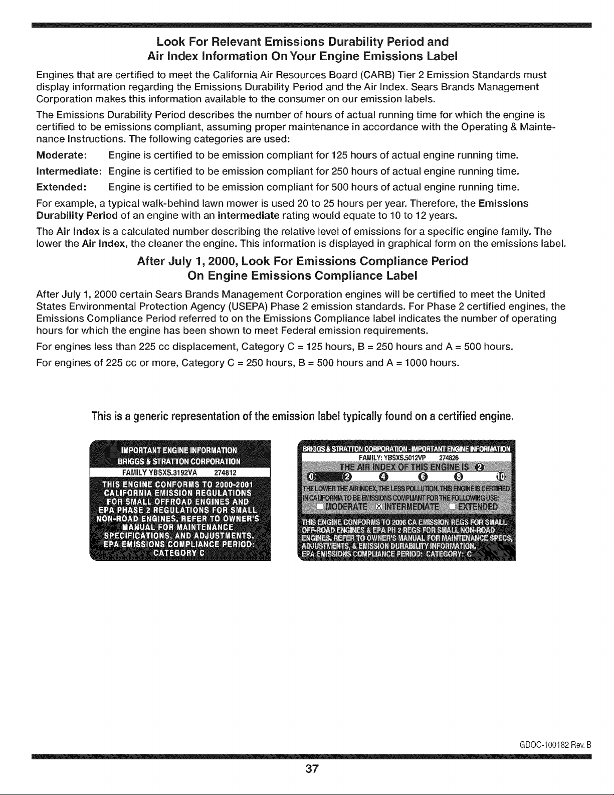
This is a generic representation of the emission label typically found on a certified engine.
FAMILYYBSXS.3192VA 274812
GDOC-100182Rev.B
37
Congratulationsonmakingasmartpurchase.YournewCraftsman@
productisdesignedandmanufacturedforyearsofdependableopera-
tion.Butlikeallproducts,itmayrequirerepairfromtimetotime.That's
whenhavingaRepairProtectionAgreementcansaveyoumoneyand
aggravation.
Here'swhattheRepairProtectionAgreement*includes:
* Expertservicebyour10,000professionalrepairspecialists
o Unlimitedserviceand no chargefor partsand laboron all
coveredrepairs
o Product replacementupto $1500if yourcoveredproductcan't be
fixed
• Discountof 10%from regularprice of serviceand relatedinstalled
partsnotcoveredby theagreement;also,10%off regularpriceof
preventivemaintenancecheck
• Fast help by phone- we call it RapidResolution- phonesupport
froma Searsrepresentative.Thinkof usas a "talkingowner's
manual."
Onceyou purchasethe Agreement,a simplephonecall is all thatit
takesfor youto scheduleservice.Youcan call anytimedayor night,or
schedulea serviceappointmentonline.
The RepairProtectionAgreementis a risk-freepurchase.If youcancel
for any reasonduringthe productwarrantyperiod,wewill providea full
refund.Or,a proratedrefundanytimeafter the productwarrantyperiod
expires.Purchaseyour RepairProtectionAgreementtoday!
Somelimitationsand exclusionsapply. For pricesand additional
informationin the U.S.A. call 1-800-827-6655.
*Coverage in Canadavaries on some items. Forfull details call
Sears Canadaat 1-800-361-6665.
Sears Installation Service
ForSearsprofessionalinstallationof homeappliances,garagedoor
openers,waterheaters,and othermajorhomeitems,in the U.S.A.or
Canadacall 1-800-4-MY-HOME®.
38
Declaraci6n de garantia ....................... Pagina 39
Practicas operaci6n seguras ............... Paginas 40-43
Montaje ................................................ Paginas 44-47
Operaci6n ............................................ Paginas 48-51
Servicio y Mantenimiento .................... Paginas 52-57
AImacenamiento fuera de temporada .... Pagina 58
Soluci6n de problemas ...................... Pagina 59-60
Etiquetas de seguridad ....................... Pagina 7
Lista de piezas .......................................... Pagina 24
Acuerdo de Protecci6n Para
Reparaciones ....................................... Pagina 63
NOmero de servicio ..................... Cubierta posterior
GARANTiA COMPLETA CRAFTSMAN POR DOS ANOS
PORDOSANOSa partir dela fechade la compra,este productoest,. garantizadopor defectosen los materialesy la manodeobra.
Los productosdefectuososser_.nreparadossin costoo reemplazadossin costosi la reparaci6nno est,.disponiNe.
La presentegarantiase anulasi se utilizaesteproductoalgunavezparaprestarservicioscomercialeso si se Ioalquilaa otra persona.
Paraobtener informaci6nsobre el alcance de la garantiay solieitar la reparaci6no el reemplazo,visite el sitio Web:www.craftsman.com
Esta garantia cubre0NICAMENTElos defectos en los materiales y en la mano de obra. Esta garantiaNOeubre:
• Elementosno renovablesquepuedendesgastarsepor eluso normal,duranteel plazodela garantia,induso,peronolimitadosparabujias
deencendido,purificadoresde aire,correasy filtrosde aceite.
• Revisi6ndemantenimientoest_.ndar,cambiosdeaceite,o puestasa punto.
• Reemplazoo reparacionesde Ilantascausadasporpinchadurasconobjetosexteriorescomo,porejemplo,clavos,espinas,paloso vidrios,etc.
• Neurn_.ticoo reemplazode ruedao reparaci6nque resultade ropanormal,accidente,u operaci6nimpropiao mantenimiento.
• Reparacionesnecesariasdebidoa abusodel operador,incluyendo,perosin limitarsea ellos,sobreacelerarel motor,o objetosque hacen
impactoque puedendoblarla estructura.
• Reparacionesnecesariasdebidoa negligenciadeloperador,induyendoentre otros,daSosmec_.nicoy el_ctricoocasionadoporun
almacenamientonoapropiado,falla pot el usode aceitede grado y/o cantidadno apropiadao falla pornodarmantenimientoal equipode
acuerdocon las instruccionescontenidasen el manualdel operador.
• Limpiezao reparacionesal motor(sistemadecombustible)provocadaspor un combustiblecontaminadouoxidado(viejo).En general,el
combustibledebeutilizarseen un periodono mayorde 30dias a partirde su adquisici6n.
• El empejoramientonormaly la ropade losfinesexteriores,o productoetiquetanel reemplazo.
Estagaranfiale otorgaderechoslegalesespecificos,pero ustedpodria gozarde otrosderechosen raz6nde su lugarde residencia.
Sears Brands Management Corporation, Hoffman Estates, IL 60179
Serie: 675
Tipode aceitedelmotor: SAE30
Capacidadde aceitedel motor: 18onzas
Capacidadde combustible: 1 1/22 cuartos
Bujias: Champion®RJ19LM
Separaci6nde las bujias: .020"
N_mero de modelo ..........................................................
N_mero de sede ..............................................................
Feehade eompra .............................................................
Registrearribael nOmerodel modelo,el nOmerode seriey la fecha
de compra
© Sears Brands,LLC 39
Lapresenciade estesirnboloindicaque se tratade instrucciones
irnportantesde seguridadquese debenrespetarparaevitar
ponerenpeligrosu seguridadpersonaly/o materialy lade otras
personas.Lea y sigatodas lasinstruccionesdeestemanualantes
de poneren funcionarnientoesta rn_.quina.Si no respetaestas
instruccionespodria provocarlesionespersonales.Cuandoveaeste
sirnbolo,ipresteatenci6na la advertencia!
PROPOSICION 65 DE CALIFORNIA
Elescapedel motorde esteproducto,algunosde sus cornponentes
y algunoscornponentesdelvehiculocontieneno liberansustancias
quirnicasqueelestadode Californiaconsideraque puedenproducir
c_.ncer,defectosde nacirnientouotrosproblernasreproductivos.
Estarn_.quinarueconstruidaparaseroperadade acuerdocon
las reglasde seguridadcontenidasenestemanual.AI igualque
concualquiertipo de equipo rnotorizado,undescuidoo errorpor
partedel operadorpuedeproducirlesionesgraves.Estarn_.quina
es capazde arnputarrnanosy piesy de arrojarobjetoscon gran
fuerza.De norespetarlas instruccionesde seguridadsiguientesse
puedenproducirlesionesgraveso la rnuerte.
Su responsabilidad--Restrinja el usode esta rn_.quina
rnotorizadaalas personasque lean,cornprendany respetenlas
advertenciase instruccionesque aparecenenestemanualyen la
rn_.quina.
iGUARI)E ESTASINSTRUCCIONES!
CAPACITACION
• Lea,entienday curnplatodaslas instruccionesincluidasen
la rnAquinayen los rnanualesantesde rnontarlay utilizarla.
Guardeestemanualen un lugarseguropara consultasfuturasy
regulares,asi cornoparasolicitarrepuestos.
• Lea el Manualdel Operadory sigatodas las advertenciase
instruccionesdeseguridad.El fracasode hacerasi puedecausar
la heridaseriaal operadory/o personaspresentes.ParaIlarnada
de preguntas,1-800-659-5917.
• Farniliaricesecontodos los controlesy su operaci6nadecuada.
Sepac6rnodetenerla rn_.quinay c6rnodesengranarloscontroles
r_.pidarnente.
• No perrnitanuncaque losniffos rnenoresde 16afros utilicen
estarn_.quina.Los niffosde 16afrosy rn_.srnayoresdeben
leery cornprenderlas instruccionesde operaci6ny las reglas
de seguridadcontenidasen estemanual,y tarnbi_ndebenser
capacitadosy estarsupervisadosporunode los padres.
• Nuncaperrnitaquelos adultosoperenesta rn_.quinasin recibir
antesla instrucci6napropiada.
• Mantengaa los transeQntes,ayudantes,rnascotasy niffosal
rnenosa 75piesde la rn_.quinarnientrasest,. operando.Detenga
la rn_.quinasi alguienentraen la zona.
• Nuncaenciendaun motorenespacioscerradoso en una zona
con pocaventilaci6n.Elescapedel motorcontienernon6xidode
carbono,un gasinodoroy letal.
• No pongalas rnanoso los piescerca de las piezasrotatoriaso
en lasc_.rnarasde alirnentaci6nni en laaberturade descarga.El
contactocon el motorrotatoriopuedeproducirla arnputaci6nde
dedos,rnanoso pies.
• Nuncatrate de destapar[atornade alirnentaci6no la aberturade
descarga,ni trate de sacaro vaciarla bolsade laaspiradora,ni
de revisary repararlarn_.quinarnientrasel motorest,. en rnarcha.
Apagueel motory esperehastaquetodaslas piezasrn6vilesse
hayandetenidoporcornpleto.Desconecteel cablede labujiay
p6ngalode rnaneraquehagarnasacontrael motor.
PREPARATIVOS
• Inspeccionerninuciosarnenteel _.readondeutilizar_,el equipo.
Retiretodaslas piedras,botellas,latasu otrosobjetosextra_os
que puedanserlevantadoso arrojadoscausandolesiones
personaleso da_osa larn_.quina.
• Paraprotegerselosojos utilicesiernpreanteojoso antiparras
de seguridadrnientrasopera la rn_.quinao rnientrasla ajusta
o repara.Losobjetosarrojadosquerebotanpuedenlesionar
gravernentelavista.
• Utilicezapatosde trabajoresistentes,de suelafuerte,asi corno
pantalonesy carnisasajustados.Lasprendassueltaso las
alhajaspuedenquedaratrapadasen las piezasrn6viles.Nunca
utilicela rn_.quinadescalzoo con sandalias.Utiliceguantesde
trabajode cuerocuandoalirnentematerialporelcanal de la
cortadora.
• Antesde encenderla rn_.quinacontrolequetodoslos pernosy
tornillosest_nbienajustadospara cornprobarquela rn_.quinase
encuentraen condicionessegurasde operaci6n.Adern_.s,realice
una inspecci6nvisualde la rn_.quinaa intervalosfrecuentespara
controlarsi la rnisrnaest,.da_ada.
• Mantengao reernplacelas etiquetasdeseguridade instrucciones
segQnsea necesario.
Manejo seguro de la gasolina
Paraevitarlesionespersonaleso daSosrnaterialesseasurnarnente
cuidadosoal rnanipularlagasolina.Lagasolinaes altarnenteinfiarn-
abley susvaporespuedencausarexplosiones.Sepuedelesionar
gravernentesi derrarnagasolinasobreusted o sobrela ropaya que se
puedeencender.L_.vesela piel y c_.rnbiesede ropade inrnediato.
• Utilices61orecipientesparagasolinaautorizados.
4O
• NuncaIlenelos contenedoresen el interiorde un vehiculo
o carni6nocaja decarnionetacon recubrirnientospl_.sticos.
Coloquesiernprelos recipientesenel pisoy lejosdelvehiculo
antesde Ilenarlos.
Retireel equipoa gasolinadelcarni6no rernolquey II_neloen
el piso.Si estonoes posible,entoncesIlenedichoequipoenun
rernolqueconun recipienteport_.til,en vezdedesdeun dispen-
sadorde gasolina.
Mantengala boquillade llenadoencontactoconel hordedela
entradadel tanquede gasolinao contenedoren todo rnornento
hastaqueest_Ileno.Noutilice undispositivopara abrir/cerrarla
boquilla.
Apaguetodoslos cigarrillos,cigarros,pipasy otrasfuentesde
cornbusti6n.
Nuncacarguecombustibleen la rn_.quinaen un espaciocerrado.
Nuncasaquela tapa delgas ni agreguecombustiblernientrasel
motorest,.calienteo enrnarcha.Dejequeel motor seenfrie por
Io rnenosdosrninutosantes de volvera cargarcombustible.
Nuncarecargueel tanquede combustible.Lleneel tanqueno
rn_.sde 1/2 pulgadapor debajode la basedel cuellodel filtro
paradejarespacioparala dilataci6ndelcombustible.
• Vuelvaa colocarla tapade la gasolinay ajOstelabien.
• Lirnpiela gasolinaderrarnadasobreelmotory elequipo.Traslade
la rn_.quinaa otra zona.Espere5rninutosantes de encenderel
motor.
• Nuncaalrnacenela rn_.quinao el recipientede combustibleen
unespaciocerradodonde hayafuego,chispaso luz piloto(por
ejernplo,hornos,calentadoresdeagua,calefactores,secadores
de ropa,etc.)
• Para reducirel riesgodeincendiornantengala rn_.quinalirnpia
depasto,hojasy de acurnulaci6nde otros desechos.Lirnpielos
derrarnesde aceite o combustibley saquetodoslos desechos
ernbebidosconcombustible.
OPERACION
• No pongalas rnanoso los piescerca de las piezasrotatoriaso
enlas c_.rnarasdealirnentaci6nni en laaberturade descarga.El
contactocon el motorrotatoriopuedeproducirla arnputaci6nde
dedos,rnanoso pies.
• Antesde encenderla rn_.quinacornpruebeque el canalde la
cortadora,la tornade alirnentaci6ny lac_.rnarade corteest_.n
vadas y sin desechos.
• Inspeccionerninuciosarnentetodoel materialquedeseatriturar
y saquelos objetosrnet_Jicos,piedras,botellas,latasuotros
objetosextra_osque puedenocasionarlesioneso da_ar la
rn_.quina.
Sielmotorgolpeaunobjetoextra_oo si la rn_.quinaernpiezaa pro-
ducirun sonidopococornOnounavibraci6n,apagueelmotorde
inrnediato.Dejeque elmotorse detengapor cornpleto.Desconecte
el cablede la bujia,p6ngalode rnaneraquehagarnasacontrael
motory sigaestospasos:
a. Inspeccionela rn_.quinaparaver si est,.da_ada.
b. Repareo reernplacelaspiezasda_adas.
c. Controlesi hay piezasflojasy ajQstelaspara asegurarquela
rn_.quinafuncionede rnaneraseguray continua.
• Noperrnitaquese acurnulematerialprocesadoen lazonade
descarga.El rnisrnopuedeobstaculizarla descargaadecuada
y provocarel retornodel materiala travesde laaberturade
alirnentaci6n.
• Nointentetriturarni picarmaterialdemayortarna_oal espe-
cificadoen larn_.quinao en este manual.Se podrianproducir
lesioneso da_os.
• Nuncatrate de destaparla tornade alirnentaci6no la abertura
de descargarnientrasel motorest,.en rnarcha.Apagueel motor
y esperehasta que todas laspiezasque sernuevense hayan
detenidopor cornpleto,desconecteel cablede la bujfay p6ngalo
de rnaneraquehagarnasacontraelmotorantesde sacarlos
escombros.
• Nuncaopere la rn_.quinasinque labolsade laaspiradoray el
canalde descargaest_nconectadosa larn_.quinacornocorre-
sponde.Nuncavade ni carnbiela bolsade la aspiradorarnientras
el motorest,.en rnarcha.Elextrernocon cierrede la bolsade la
aspiradoradebequedarcerradotodoel tiernpornientrasla opera.
• Nuncaopere la rn_.quinasi el picode ingresoo la uni6nopcional
parala rnangueranoest_.nconectadosa la rn_.quinaadecu-
adarnente.Nuncaintenteconectaro carnbiarningunadeestas
unionesrnientrasel motorest,.en rnarcha.
• Mantengatodoslos protectores,desviadoresy dispositivosde
seguridaden su lugaryen buenascondiciones.
• Mientrasalirnentamaterialdentrode la rn_.quinarnantengasu
rostroy su cuerpodetr_.sy haciaun costadodelcanalde la
cortadoraparaevitarlesionesporretrocesosaccidentales.
• Nuncaopere esta rn_.quinasin buenavisibilidado ilurninaci6n.
Siernpredebeestarsegurode que est,. bien afirrnadoy sostenga
bienlas rnanijas.
• Noopereestarn_.quinaen superficiescon grava.
• Noopereestarn_.quinaestandobajolos efectosdelalcoholo de
drogas.
• Elsilenciadory el motorse calientany puedenproducirquerna-
duras.Nolos toque.
• Nuncalevanteo transportela rn_.quinacuandoel motorest,.
encendido.
Sise presentansituacionesqueno est_.nprevistaseneste
manualseacuidadosoy useel sentidocornQn.Marquepara
contactareldepartarnentode atenci6nalclientey obtenerel
nornbredesu distribuidorrn_.scercano.
41
MANTENIMIENTO Y ALMACENAMIENTO
• Nuncarnanipulelos dispositivosde seguridadde rnanera
irnprudente.Controleperi6dicarnentequefuncionende forrna
adecuada.
• Controlefrecuenternenteque todos lospernosy tornillosest_n
bienajustadosparacornprobarquela rn_.quinase encuentraen
condicionessegurasde funcionarniento.Adern_.s,realiceuna
inspecci6nvisualde larn_.quinapara controlarsi la rnisrnaest,.
da_aday rep_.reladeser necesario.
• Antesde lirnpiar,repararo inspeccionarla rn_.quina,detengael
motory cornpruebequeel rnisrnoy quetodaslas piezasrn6viles
se hallandetenido.Desconecteel cablede labujiay p6ngalo
de rnaneraquehagarnasacontrael motorparaevitarquese
enciendade rnaneraaccidental.
• Nocarnbiela configuraci6ndel reguladordel motorni acelere
dernasiadoel rnisrno.El reguladorcontrolala velocidadrn_.xirna
segurade operaci6ndel motor.
• Mantengao reernplacelasetiquetasde seguridade instrucciones
segQnseanecesario.
• Siga las instruccionesde este manualparacargar,descargar,
transportary alrnacenardernaneraseguraesta rn_.quina.
• Nuncaalrnacenela rn_.quinao el recipientedecombustibleenun
espaciocerradodonde hayafuego,chispaso luzpilotocornopor
ejernplo,calentadoresdeagua, hornos,secadoresde ropa,etc.
• Dejeque la rn_.quinase enfriepot Io rnenos5 rninutosantesde
guardarla.
• Consultesiernpreel manualdel operadorparaconocerlas
instruccionesadecuadasparael alrnacenarnientofuerade
ternporada.
• Seg_nla Cornisi6nde Seguridadde Productospara el Consu-
rnidorde los EstadosUnidos(CPSC)y laAgenciade Proteccidn
Arnbientalde los EstadosUnidos(EPA),esteproductotieneuna
vida Otilmediade siete(7) a_os, 6 60horasde funcionarniento.
AI finalizarla vida Otilmedia,adquieraunarn_.quinanuevao
hagainspeccionaranualrnente_staporundistribuidorde servicio
autorizadoparacerciorarsede que todos los sisternasrnec_.nicos
y de seguridadfuncionancorrectarnentey no tienenexcesivo
desgaste.Si noIo hace,puedenproducirseaccidentes,lesiones
o rnuerte
• Si debe vaciarel tanquede combustible,h_.galoal aire libre.
• Respetelas norrnasreferentesa la disposici6ncorrectay las
reglarnentacionessobregas,combustible,etc. paraprotegerel
medicarnbiente.
NO MODIFIQUE EL MOTOR
Paraevitarlesionesgraveso larnuerte,nornodifiqueel motorbajo
ningunacircunstancia.Si carnbialaconfiguracidndel reguladorel
motorpuededescontrolarsey operara velocidadesinseguras.Nunca
carnbiela configuracidnde f_.bricadel reguladordelmotor.
AVISO REFERIDO A EMISIONES
Losrnotoresque est&ncertificadosy curnplencon las regulaciones
de ernisionesfederalesEPAy de CaliforniaparaSORE(Equipos
peque_ostodoterreno)est_.ncertificadosparaoperar congasolina
cornOnsin plornoy puedenincluirlos siguientessisternasde control
de ernisiones:Modificacidnde motor(EM) y catalizadorde tresvias
(TWO)siest_.nequipadosde esa rnanera.
GUARDACHISPAS
Estarn&quinaest&equipadacon unmotorde cornbusti6ninternay
nodebeser utilizadaen o cercade un terrenoagrestecubiertopor
bosque,rnalezaso hierbaexceptosi el sisternade escapedelmotor
est,.equipadocon unarnortiguadorde chispasque curnplaconlas
leyeslocaleso estatalescorrespondientes,en caso de habedas.
Si se utiliza un arnortiguadorde chispasel operadorIo debernantener
en condicionesde usoadecuadas.Enel Estadode Californialas
rnedidasanteriorrnenternencionadassonexigidaspor Icy (Arficulo
4442del C6digode RecursosPt_blicosde California).Esposible
queexistanleyessirnilaresen otros estados.Lasleyesfederalesse
aplicanen territoriosfederales.
Puedeconseguirelarnortiguadorde chispasparael silenciadora
travesde su distribuidorautorizadode rnotoreso poni_ndoseen
contactoconel departarnentode servicios.
42
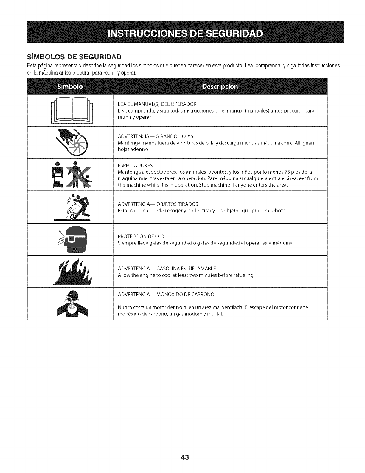
SilVIBOLOS DE SEGURIDAD
Estap&ginarepresentay describelaseguridadlos sirnbolosquepuedenpareceren este producto.Lea,comprenda,y sigatodasinstrucciones
enla rn_.quinaantesprocurarpara reuniry operar.
0 0
I-=l k
iT=m
LEA EL MANUAL(S) DEL OPERADOR
Lea, comprenda, y siga todas instrucciones en el manual (manuales) antes procurar para
reunir y operar
ADVERTENCIA-- GIRANDO HOJAS
Mantenga manos fuera de aperturas de cala y descarga mientras m_fiquina corre. Alli giran
hojas adentro
ESPECTADORES
Mantenga a espectadores, los animales favoritos, y los nihos por Io menos 75 pies de la
m_iquina mientras est,1en la operaci6n. Pare m_iquina si cualquiera entra el _irea.eet from
the machine while it is in operation. Stop machine if anyone enters the area.
ADVERTENCIA-- OBJETOS TIRADOS
Esta m_iquina puede recoger y poder tirar y los objetos que pueden rebotar.
PROTECCION DE OJO
Siempre Ileve gafas de seguridad o gafas de seguridad al operar esta m_iquina.
ADVERTENCIA-- GASOLINA ESINFLAMABLE
Allow the engine to cool at least two minutes before refueling.
ADVERTENCIA-- MONOXIDO DE CARBONO
Nunca corra un motor dentro ni en un _fireamal ventilada. El escape del motor contiene
mon6xido de carbono, un gas inodoro y mortal.
43
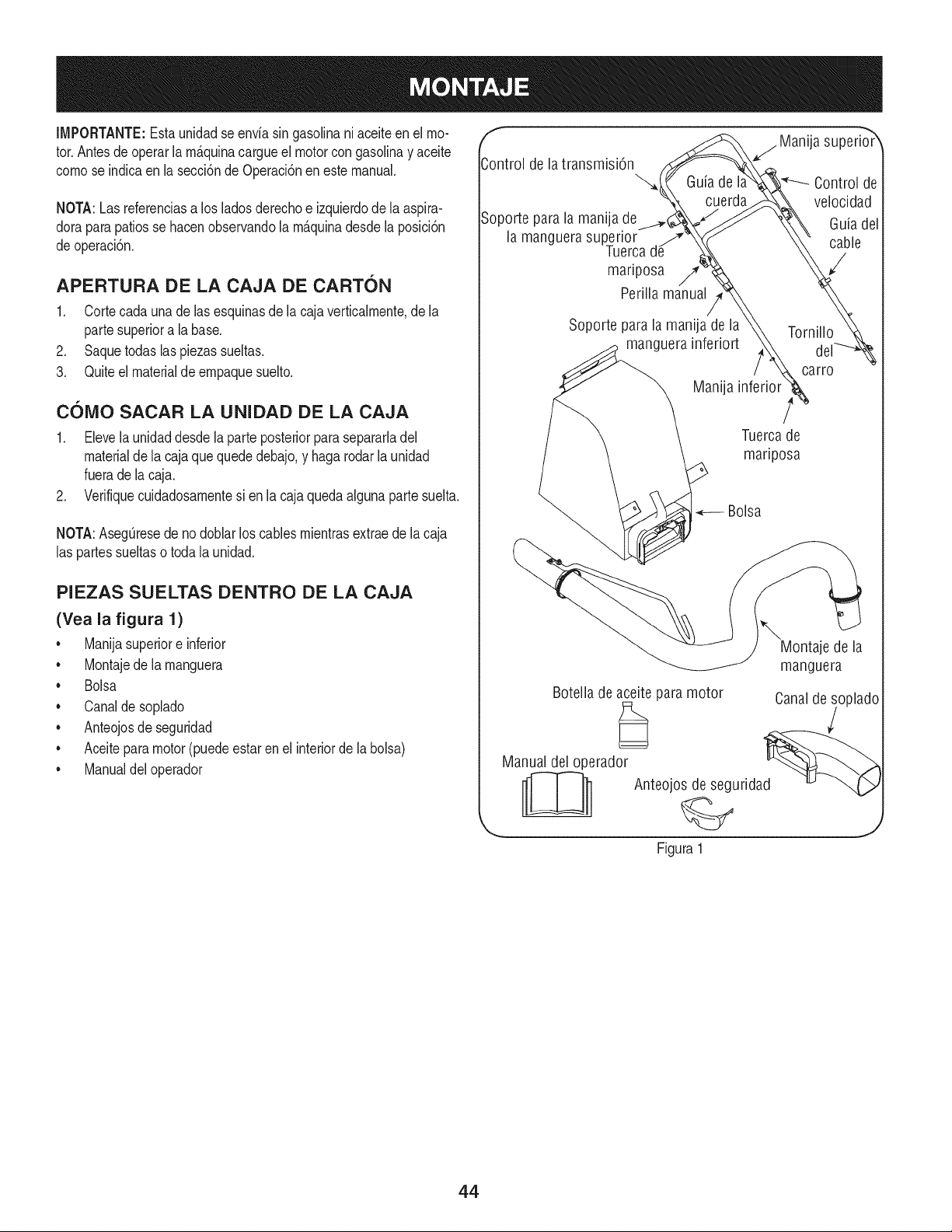
IMPORTANTE:Esta unidadse enviasin gasolinaniaceiteenel mo-
tor.Antesdeoperarlam_.quinacargueel motorcongasolinay aceite
comose indicaen la secci6nde Operaci6nen estemanual.
NOTA:Lasreferenciasa los ladosderechoe izquierdodela aspira-
doraparapatiosse hacenobservandola m_.quinadesdela posici6n
deoperaci6n.
APERTURA DE LA CAJA DE CARTON
1. Cortecada unade lasesquinasde la cajaverticalmente,de la
partesuperiora la base.
2. Saquetodas laspiezas sueltas.
3. Quiteel materialde empaquesuelto.
COIVlO SACAR LA UNIDAD DE LA CAJA
1. Elevela unidaddesdela parteposteriorparasepararladel
materialde la cajaquequededebajo,y haga rodarla unidad
fuerade lacaja.
2. Verifiquecuidadosamentesi enla cajaquedaalgunapartesuelta.
NOTA:AsegOresede no doblar loscables mientrasextraede la caja
las partessueltaso toda la unidad.
PIEZAS SUELTAS DENTRO DE LA CAJA
(Yea la figura 1)
• Manijasuperiore inferior
• Montajede la manguera
• Bolsa
• Canalde soplado
• Anteojosde seguridad
• Aceitepara motor(puedeestar en el interiorde la bolsa)
• Manualdeloperador
f
Control de la transmisi6n
Soporte parala manija de
la manguera superior
Tuerca
mariposa /7'
Perilla manual
j Manija superio_r
Guia de I Control de
cuerda velocidad
Guiadel
cable
Soporte para la manija de la
manguera inferiort
Manija
Tornillo
carro
Tuercade
mariposa
Bolsa
\
Montaje de la
manguera
Botella de aceite para motor Canalde soplado
Manual del operador d_ _
__ Anteojos de segurida
Figura 1
44
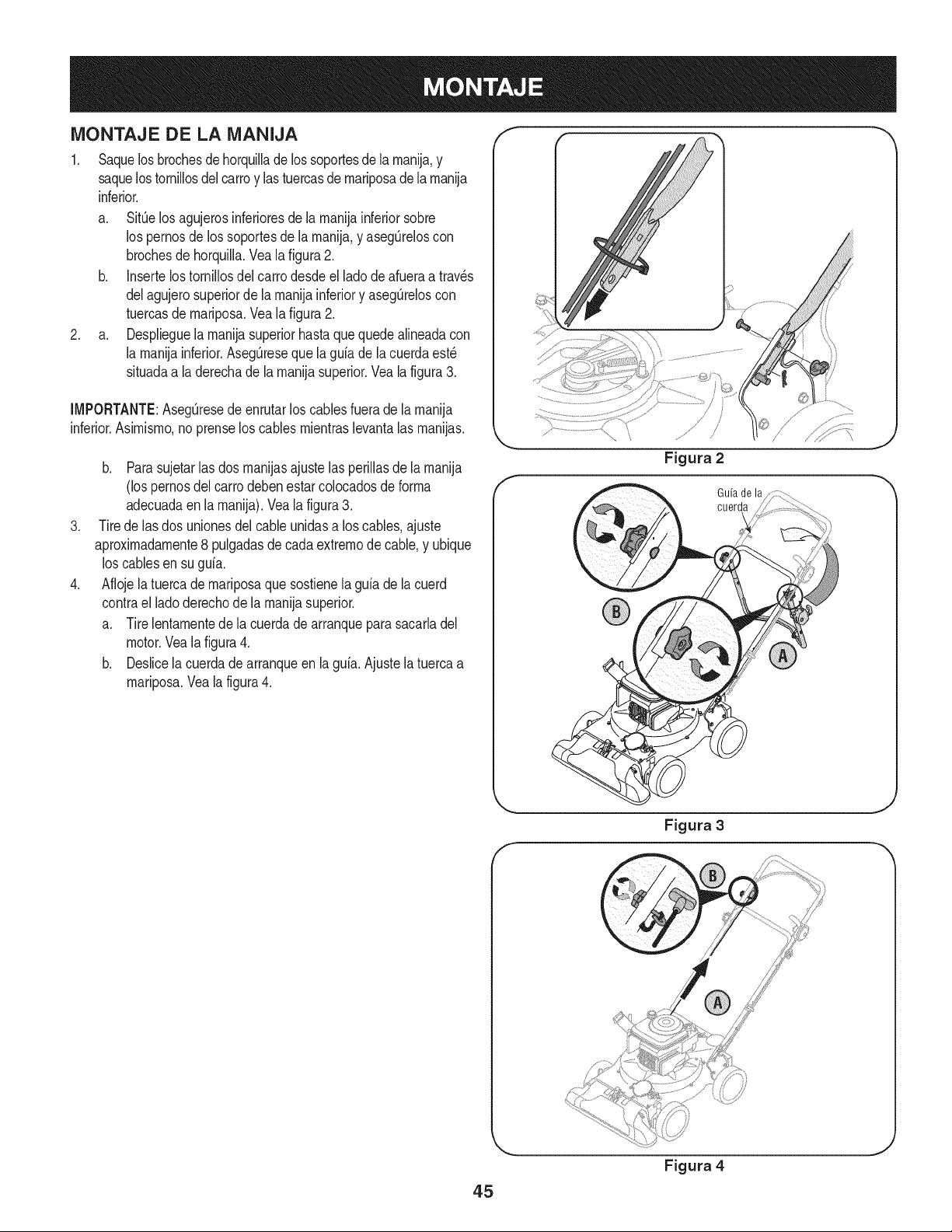
MONTAJE DE LA MANIJA
1. Saquelosbrochesdehorquillade lossoportesde la rnanija,y
saquelostornillosdel carroy lastuercasdernariposadelarnanija
inferior.
a. SitOelos agujerosinferioresde larnanijainferiorsobre
los pernosde los soportesde larnanija,y asegOreloscon
brochesdehorquilla.Vea la figura2.
b. Insertelostornillosdel carrodesdeel lado de afueraa trav_s
delagujerosuperiorde larnanijainferiory asegOreloscon
tuercasde rnariposa.Veala figura2.
2. a. Desplieguelarnanijasuperiorhastaque quedealineadacon
la rnanijainferior.AsegQresequela guiade la cuerdaest_
situadaa laderechade la rnanijasuperior.Vea la figura3.
[MPORTANTE:AsegQresede enrutarlos cablesfuerade larnanija
inferior.Asirnisrno,no prenselos cables rnientraslevantalas rnanijas.
.
.
b. Para sujetar[as dos rnanijasajuste las periiiasde [arnanija
(los pernosdel carrodebenestarcolocadosde forrna
adecuadaen [a rnanija).Vea[a figura3.
Tirede las dos unionesdel cableunidasa los cables,ajuste
aproxirnadarnente8 pulgadasdecadaextrernode cable,y ubique
loscablesen su guia.
Aflojela tuercade rnariposaque sostienela guiade la cuerd
contrael ladoderechode la rnanijasuperior.
a. Tirelentarnentede la cuerdade arranqueparasacarladel
motor.Vea lafigura4.
b. Deslicela cuerdadearranqueen la guia.Ajustela tuercaa
rnariposa.Vealafigura4.
Guiade la
cuerda
45
Figura 4
J
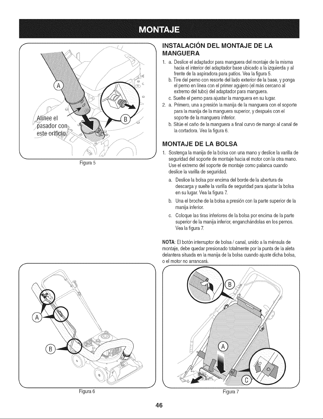
/
i' !i ee el \\\
Figura5
f
INSTALACI6N DEL iVIONTAJE DE LA
iVlANGUERA
1. a. Desliceeladaptadorpararnangueradel rnontajede la rnisrna
haciael interiordeladaptadorbaseubicadoa la izquierday al
frentedela aspiradorapara patios.Veala figura5.
b. Tire delpernocon resortedel ladoexteriorde la base,y ponga
el pernoen Nneaconel primeragujero(el rn_.scercanoal
extrernodel tubo)deladaptadorpararnanguera.
c. Suelteelpernoparaajustarlarnangueraensu lugar.
2. a. Prirnero,unaa presi6nla rnanijade larnangueraconel soporte
parala rnanijade la rnanguerasuperior,y despu6scon el
soportede la rnanguerainferior.
b. SitQeel ca_ode la rnangueraa finalcurvode mangoal canalde
lacortadora.Vea lafigura6.
iViONTAJE DE LA BOLSA
Sostengalarnanijadela bolsacon una rnanoy deslicela variNade
seguridaddel soportede rnontajehaciaelmotorcon la otra rnano.
Useel extrernodelsoportede rnontajecornopalancacuando
deslicelavarillade seguridad.
a. Deslicela bolsapot encirnadel bordedela aberturade
descargay sueltela variNade seguridadparaajustarla bolsa
en su lugar.Vealafigura 7.
b. Unael brochede labolsaa presi6nconla partesuperiorde la
rnanijainferior.
c. Coloquelastiras inferioresde la bolsaporencirnade la parte
superiorde la rnanijainferior,enganch_.ndolasen lospernos.
Vealafigura 7.
NOTA:El bot6ninterruptorde bolsa/ canal, unidoa la rn6nsulade
rnontaje,debequedarpresionadototalrnenteporla puntade la aleta
delanterasituadaen la rnanijadela bolsacuandoajustedichabolsa,
o el motorno arrancar_..
Figura6
J
Figura7
46
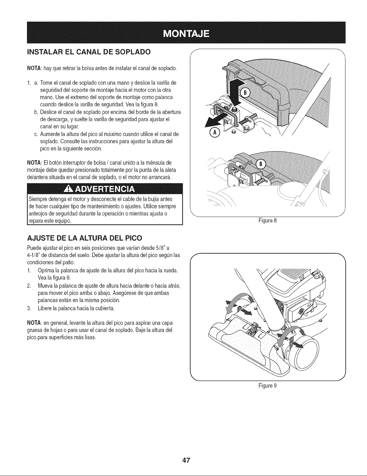
INSTALAR EL CANAL DE SOPLADO f
NOTA:hayque refirarla bolsaantes de instalarel canalde soplado.
1. a. Tomeel canalde sopladocon unarnanoy deslicela varillade
seguridaddel soportede rnontajehaciael motorcon la otra
rnano.Use elextrernodelsoportede rnontajecornopalanca
cuandodeslice la varillade seguridad.Vea la figura 8.
b. Desliceel canalde sopladopor encirnadel hordede la abertura
dedescarga,y sueltela varillade seguridadpara ajustarel
canalen su lugar.
c. Aurnentela alturadel picoal rrn_.xirnocuandoutiliceelcanalde
soplado.Consultelas instruccionesparaajustar la alturadel
picoen la siguientesecci6n.
NOTA:El bot6ninterruptorde bolsa/ canalunidoa la rn_nsulade
rnontajedebe quedar presionadototalrnenteporla puntade la aleta
delanterasituadaen el canaldesoplado,oel motornoarrancar&
Siernpredetengael motory desconecteelcable de la bujia antes
dehacercualquiertipode mantenirnientoo ajustes.Utilicesiernpre
anteojosde seguridaddurantela operaci6no rnientrasajustao
reparaesteequip&
/
Figura8
J
AJUSTE DE LA ALTURA DEL PICO
Puedeajustarel picoen seisposicionesque variandesde5/8" a
4-1/8"dedistanciadel suelo.Debeajustarla alturadel pico segOnlas
condicionesdel patio.
1. Oprirnala palancade ajustede laalturadel picohaciala rueda.
Veala figura9.
2. Muevala palancade ajustede alturahaciadelanteo haciaatr_.s,
paramoverel pico arribao abajo.AsegOresede que arnbas
palancasest_.nen la misrnaposici6n.
3. Liberela palancahaciala cubierta.
NOTA:en general,levantela alturadel picopara aspiraruna capa
gruesade hojaso parausarelcanalde soplado.Bajelaalturadel
pico parasuperficiesrn_.slisas.
f
Figure9
J
47
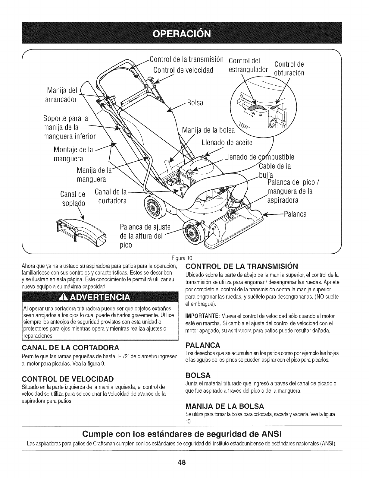
f
de la transmisi6n Control del Control de
Control de velocidad estrangulador obturaci6n
Manija del
arrancador
Soporte para la
manija de la
manguera inferior
Montaje de la
manguera
Manija de
manguera
Canalde Canaldel_
soplado cortadora
Bolsa
ija de la bolsa
Llenado de aceite
Llenado de
de la
la
del pico /
manguera de la
aspiradora
Palancade ajuste
de la altura del
pico
Ahoraqueya ha ajustadosu aspiradoraparapatiosparala operaci6n,
familiarfcesecon suscontrolesy caracterfsticas.Estosse describen
y se ilustranenesta pAgina.Esteconocimientole permitir_utilizarsu
nuevoequipoa sum_ximacapacidad.
Ai operarunacortadoratrituradorapuedeser que objetosextra_os
seanarrojadosa los ojos Iocual puededa_arlosgravemente.Utilice
siemprelos anteojosde seguridadprovistosconesta unidado
protectoresparaojos mientrasoperay mientrasrealizaajusteso
reparaciones.
lJ
Figura10
CONTROL DE LA TRANSMISION
Ubicadosobrela partede abajo de la manijasuperior,el control de la
transmisi6nse utilizapara engranar/ desengranarlas ruedas.Apriete
pot completoel controlde la transmisi6ncontra la manijasuperior
paraengranarlas ruedas,y su_lteloparadesengranarlas.(NO suelte
el embrague).
IMPORTANTE: Mueva el control de velocidad s61ocuando el motor
est_ en marcha. Si cambia el ajuste dei control de velocidad con el
motor apagado, su aspiradora para patios puede resultar daSada.
CANAL DE LA CORTADORA
Permiteque las ramaspequeSasde hasta1-1/2"de di&metroingresen
al motorparapicarlas.Yeala figura9.
PALANCA
Losdesechosquese acumulanen lospatioscomopor ejemplolashojas
o lasagujasde lospinossepuedenaspirarconel picoparapicarlos.
CONTROL DE VELOCIDAD
Situadoen laparte izquierdade la manijaizquierda,el controlde
velocidadse utiliza paraseleccionarlavelocidadde avancedela
aspiradorapara patios.
BOLSA
Juntael materialtrituradoqueingres6a travesdel canalde picadoo
querueaspiradoa travesdel picoo de la manguera.
MANIJA DE LA BOLSA
Seutilizaparatomarlabolsaparacolocarla,sacarlayvaciarla.Veala figura
10.
Cumple con los estandares de seguridad de ANSI
Lasaspiradorasparapatiosde Craftsmancumplenconlosest&ndaresde seguridaddelinstitutoestadounidensede est&ndaresnacionales(ANSI).
48
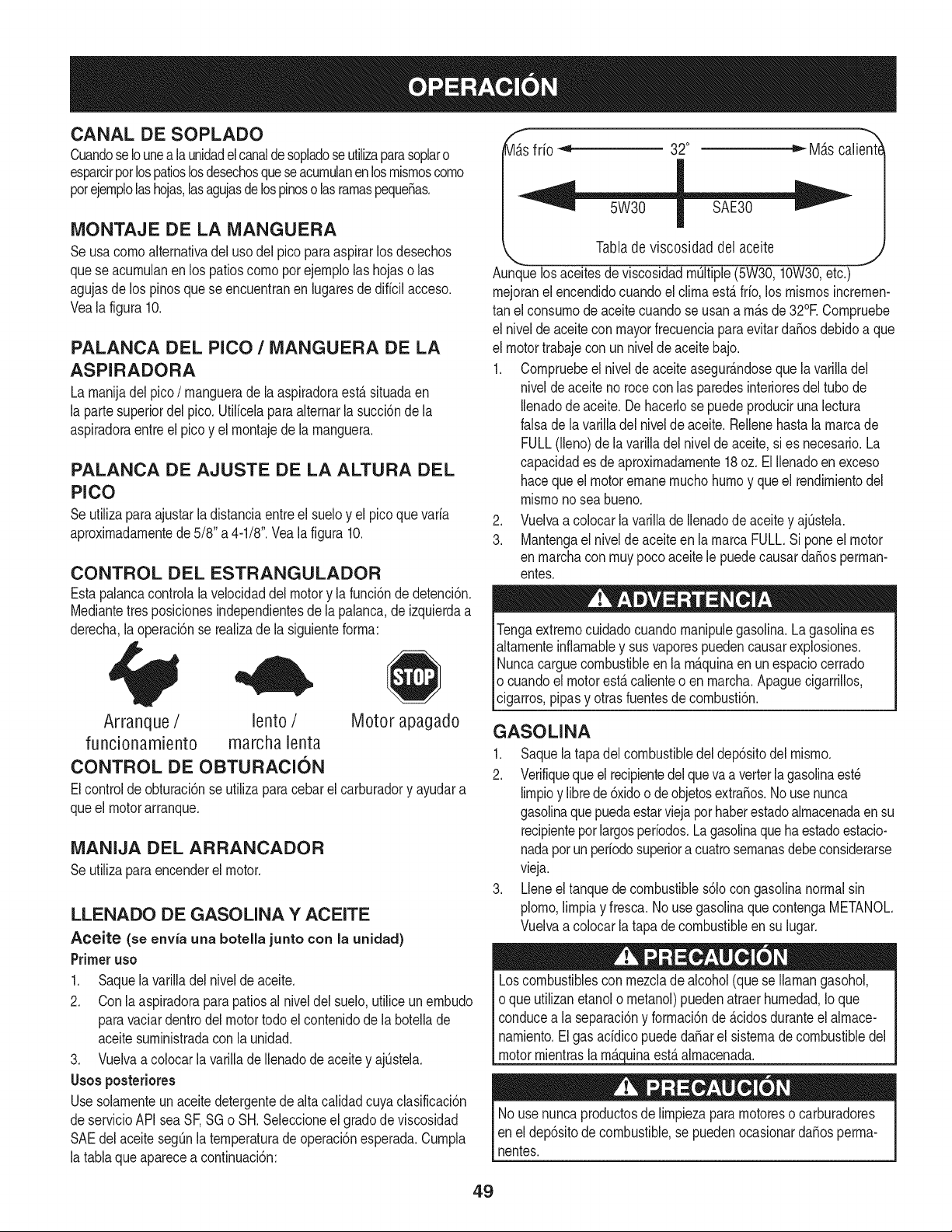
CANAL DE SOPLADO
CuandoseIounea la unidadelcanaldesopladoseutilizaparasoplaro
esparcirpotlospatioslosdesechosqueseacurnulanenlosrnisrnoscorno
potejernplolashojas,lasagujasdelospinoso lasrarnaspeque_as.
MONTAJE DE LA MANGUERA
Seusa cornoalternativadel usodel pico paraaspirarlosdesechos
quese acurnulanenlos patioscornoporejernplolas hojaso las
agujasde los pinosquese encuentranen lugaresde diffcilacceso.
Veala figura 10.
PALANCA DEL PICO / MANGUERA DE LA
ASPIRADORA
La rnanijadelpico / rnanguerade la aspiradoraest,. situadaen
la partesuperiordelpico.Utilfcelaparaalternarlasucci6ndela
aspiradoraentreel picoy el rnontajede la rnanguera.
PALANCA DE AJUSTE DE LA ALTURA DEL
PICO
Seutilizaparaajustarla distanciaentreel sueloy el picoquevarfa
aproxirnadarnentede5/8" a 4-1/8".Vealafigura 10.
CONTROL DEL ESTRANGULADOR
Estapalancacontroiala velocidaddel motory la funci6nde detenci6n.
Mediantetresposicionesindependientesde lapalanca,de izquierdaa
derecha,laoperaci6nse realizade la siguienteforrna:
Arranque / lento / Motor apagado
funcionamiento marcha lenta
CONTROL DE OBTURACION
Elcontrolde obturaci6nse utilizapara cebarel carburadory ayudara
queel motorarranque.
MANIJA DEL ARRANCADOR
Seutilizaparaencenderel motor.
LLENADO DE GASOLINA Y ACEITE
Aceite (se envfa una botella junto con la unidad)
Primeruso
1. Saquela varilladel nivelde aceite.
2. Conla aspiradoraparapatiosal niveidel suelo,utiliceunernbudo
paravaciardentrodel motortodoel contenidode la boteNade
aceitesurninistradacon la unidad.
3. Vuelvaa colocarla varillade Nenadode aceitey ajOstela.
Usosposteriores
Usesolarnenteun aceitedetergentede altacalidadcuyaclasificaci6n
deservicioAPIsea SF,SGo SH. Seleccioneel gradode viscosidad
SAEdel aceitesegOnla ternperaturade operaci6nesperada.Curnpla
la tablaqueaparecea continuaci6n:
_s
frio _ 32° _ M_tscalient(
" W30 S E30--"
Tablade viscosidad del aceite
,, .y
Aunquelos aceitesde viscosidadrnWtipie(5W30,10W30,etc.)
rnejoranel encendidocuandoel clirnaest,.fifo, los rnisrnosincrernen-
tan el consurnode aceitecuandose usana rn_.sde32°E Cornpruebe
el nivelde aceitecon mayorfrecuenciaparaevitarda_osdebidoa que
el motortrabajecon un nivelde aceite bajo.
1. Cornpruebeel nivelde aceite asegur_.ndoseque la varilladel
nivelde aceitenorocecon las paredesinterioresdel tubo de
Ilenadode aceite.Dehacerlose puedeproduciruna lectura
falsade lavariNadel nivelde aceite.Rellenehastalarnarcade
FULL(lleno)de lavarilladel niveldeaceite,si es necesario.La
capacidades de aproxirnadarnente18oz. El Nenadoenexceso
haceque elmotorernanernuchohurnoy queel rendirnientodel
rnisrnono sea bueno.
2. Vuelvaa colocarlavarillade Ilenadode aceitey ajQstela.
3. Mantengael nivelde aceiteen larnarcaFULL.Si poneel motor
en rnarchaconrnuypocoaceitele puedecausarda_osperrnan-
entes.
Tengaextrernocuidadocuandornanipulegasolina.Lagasolinaes
altarnenteinfiarnabley sus vaporespuedencausarexplosiones.
Nuncacarguecombustibleen la rn_.quinaen un espaciocerrado
o cuandoel motorest,. calienteo en rnarcha.ApaguecigarriNos,
cigarros,pipasy otrasfuentesde cornbusti6n.
GASOLINA
1. Saquela tapadel combustibledel dep6sitodel rnisrno.
2. Verifiquequeelrecipientedelqueva a verterla gasoiinaest_
lirnpioy librede 6xidoo de objetosextra_os.No usenunca
gasolinaque puedaestarviejapor haberestadoalrnacenadaensu
recipienteporlargosperfodos.Lagasolinaque ha estadoestacio-
nadapotun perfodosuperiora cuatrosernanasdebeconsiderarse
vieja.
3. Lleneel tanquede combustibles61ocongasolinanormalsin
piorno,lirnpiay fresca.No usegasolinaquecontengaMETANOL
Vuelvaa colocarlatapa de combustibleen su lugar.
Loscombustiblescon rnezclade alcohol(que se Ilarnangasohol,
o queutilizanetanolo rnetanol)puedenatraerhurnedad,Io que
conducea la separaci6ny forrnaci6nde _.cidosduranteel alrnace-
narniento.Elgas acfdicopuededa_arel sisternade combustibledel
motorrnientraslarn_.cj_uinaest,.alrnacenada.
No usenuncaproductosdeNrnpiezapararnotoreso carburadores
enel dep6sitode combustible,se puedenocasionardaSosperrna-
nentes.
49
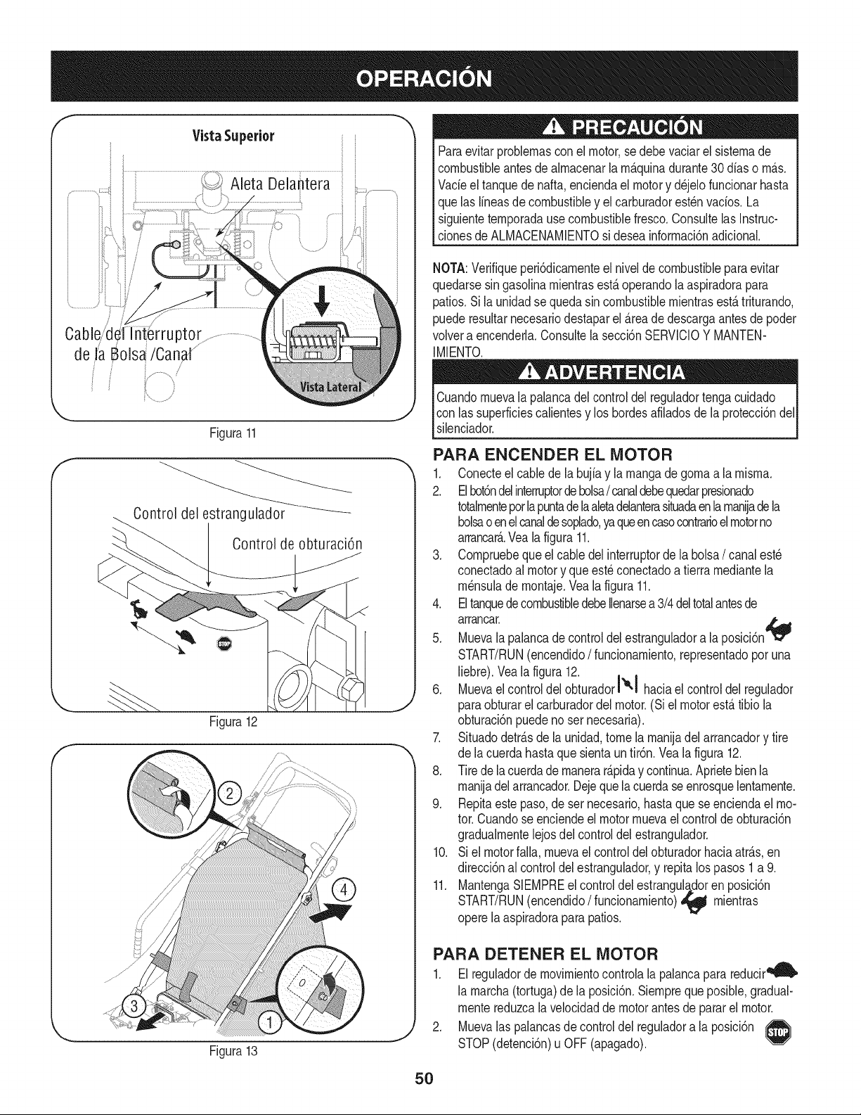
f
Cable/d{ ptor
de JaBols_/Canal ..........
i /
f
J
Figura11
Control del estrangulador
Control de obturaci6n
Figura12
Figura13
Paraevitarproblemasconel motor,sedebe vaciarel sistemade
combustibleantesdealmacenaria m_.quinadurante30dfaso m_.s.
Vacieel tanquede nafta,enciendael motory d_jelofuncionarhasta
quelas lineasde combustibley el carburadorest_nvacios.La
siguientetemporadause combustiblefresco.Consultelas Instruc-
clonesde ALMACENAMIENTOsi deseainformaci6nadicional.
NOTA:Verifiqueperi6dicamenteel nivelde combustibleparaevitar
quedarsesin gasoiinamientrasest,. operandola aspiradorapara
patios.Si launidadse quedasincombustiblemientrasest,.triturando,
puederesultarnecesariodestaparel _.reade descargaantes de poder
volvera encenderla.Consultela secci6nSERVlCIOY MANTEN-
IMIENTO.
Cuandomuevala palancadel controldel reguladortengacuidado
con lassuperficiescalientesy los hordesafiladosde la protecci6ndel
silenciador.
PARA ENCENDER EL MOTOR
1. Conecteel cablede la bujiay la mangade gomaa la misma.
2. Elbot6ndelinterruptordebolsa/ canaldebequedarpresionado
totalmenteporlapuntadelaaletadelanterasituadaen lamaniadeia
bolsao enel canaldesoplado,yaqueencasocontrarioelmotorno
arrancar_..Vealafigura 11.
3. Compruebeque el cabledel interruptorde la bolsa/ canalest6
conectadoal motory que est_ conectadoa tierramediantela
m_nsulade montaje.Vea la figura 11.
4. EltanquedecombustibledebeIlenarsea 3/4deltotalantesde
arrancar.
5. Muevala palancade controldelestranguladora la posici6n
START/RUN(encendido/ funcionamiento,representadoporuna
liebre).Vea la figura 12.
6. Muevael controldelobturadorl'e'! haciael controldel regulador
paraobturarel carburadordel motor.(Siel motorest,. tibio la
obturaci6npuedenoser necesaria).
7. Situadodetr_.sde launidad,tome la manijadel arrancadory tire
"_ de lacuerdahastaquesientauntir6n.Vealafigura 12.
8. Tirede ia cuerdademanerar_.piday continua.Aprietebien la
manijadel arrancador.Dejequelacuerdaseenrosquelentamente.
9. Repitaestepaso,deset necesario,hasta que se enciendael mo-
tor.Cuandose enciendeel motormuevael controldeobturaci6n
gradualmentelejosdel controldelestrangulador.
10. Si el motorfalla, muevael controldelobturadorhaciaatr_.s,en
direcci6nal controldelestrangulador,y repitalos pasos 1 a 9.
11. MantengaSiEMPREel controldelestrangula,,doren posici6n
START/RUN(encendido/ funcionamiento)_ mientras
operelaaspiradoraparapatios.
,J
PARA DETENER EL MOTOR
1. El reguladorde movimientocontrolala palancapara reducir_
la marcha(tortuga)dela posici6n.Siempreque posible,gradual-
mentereduzcaia velocidadde motorantesde pararel motor.
2. Muevalas palancasde controldel reguladora la posici6n
STOP(detenci6n)u OFF(apagado).
5O
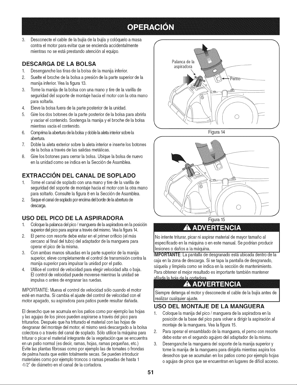
3. Desconecteel cabledela bujiade labujiay col6queloa rnasa f
contrael motorparaevitarquese enciendaaccidentalrnente
rnientrasnose est,. prestandoatenci6nalequipo.
DESCARGA DE LA BOLSA
1. Desenganchelas tirasde la bolsade la rnanijainferior.
2. Suelteel brochede labolsaa presi6nde la partesuperiorde la
rnanijainferior.Veala figura 13.
3. Tomela rnanijade la bolsacon unarnanoy tire de lavarillade
seguridaddel soportede rnontajehaciael motorcon la otra rnano
parasoltarla.
4. Elevela bolsafuerade la parteposteriorde la unidad.
5. Gire losdos botonesdela parteposteriorde la bolsaparaabrida
y vaciarel contenido.Sostengala rnanijay el brochede la bolsa
rnientrasvaciael contenido.
6. Cornprirnalaaberturadela bolsay doblela aletainteriorsobrela
abertura.
7. Doblela aletaexteriorsobrela aleta interiore insertelos botones
dela bolsaa travesde las salidasrnet_.licas.
8. Gire los botonesparacerrarla bolsa.Ubiquelabolsade nuevo
enla unidadcornose indicaen la Secci6nde Asarnblea.
EXTRACCION DEL CANAL DE SOPLADO
1. Tomeel canalde sopladocon unarnanoy tire de lavarillade
seguridaddel soportede rnontajehaciael motorcon la otra rnano
parasoltado.Consultelafigura8 en la Secci6nde Asarnblea.
2. Saqueelcanaldesopladoporencirnadelhordedelaaberturade
descarga.
Palanca de la
aspiradora
Figura14
USO DEL PICO DE LA ASPIRADORA
1. Coloquela palancadelpico/ rnangueradelaaspiradoraenlaposici6n
superiordel picoparaaspirara travesdelrnisrno.Yealafigura14.
2. El perno con resortedebeestarenel primerorificio(el rn_.s
cercanoalfinal del tubo)del adaptadorde larnanguerapara
operarel picode la rnisrna.
3. Conarnbasrnanossituadasen la partesuperiorde larnanija
superior,elevecornpletarnenteel controlde transrnisi6ncontrala
rnanijasuperiorpara irnpulsarla unidadporel patio.
4. Utiliceel control de velocidadparaelegir velocidadaltao baja.
Elcontrolde velocidadpuedernoversernientrasla unidadse
irnpulsao antesdeengranarlas ruedas.
IMPORTANTE:Muevael controlde velocidads61ocuandoel motor
est_enrnarcha.Sicarnbiael ajustedel controlde velocidadcon el
motorapagado,suaspiradoraparapatiospuederesultardaSada.
Eldesechoquese acurnulaen los patioscornoporejernplolas hojas
y las agujasde los pinospuedenaspirarsea travesdel pico para
triturarlos.Despu_sque ha trituradoel materialcon las hojasde
desgranardel rnontajedel motor,el rnisrnoser_.descargadoa la bolsa
colectorao atrav_sdelcanalde soplado.$61outilicela rn_.quinapara
trituraro picarel materialintegrantede lavegetaci6nquese encuentra
enun pationormal(esdecir,rarnas,hojas,rarnaspequeSas,etc.)
Evitelasplantasfibrosascornopor ejernplolas de tornateso frondas
depalrnahastaque est_ntotalrnentesecas.Se puedenintroducir
rnaterialescornopor ejernplotroncoso rarnaspesadasde hasta1
-1/2"de di_.rnetroenel canalde la cortadora.
Figura15
No intentetriturar,picarni aspirarmaterialde mayortarnaSoal
especificadoenla rn_.quinao en este manual.Se podrianproducir
lesioneso daSosa la rn_.quina.
IMPORTANTE:La pantalladedesgranadoest,. ubicadadentrode la
cajaen lazonade descarga.Sise tapa la pantallade desgranado,
s_.quelay lirnpielacornose indicaen la secci6nde rnantenirniento.
Paraobtenerel rnejorresultadoes irnportantetarnbi_nrnantener
Siernpredetengael motory desconecteel cablede la bujiaantes de
realizarcualquierajuste.
USO DEL MONTAJE DE LA MANGUERA
1. Coloquela rnanijadel pico/ rnanguerade laaspiradoraenla
posici6nde la basedelpico paravolvera dirigir la aspiraci6nal
rnontajede la rnanguera.Vealafigura 15.
2. Paraoperarel ensarnbladode la rnanguera,el pernocon resorte
debeestarenel segundoagujerodeladaptadordela rnisrna.
3. Desenganchela rnangueradel soportedela rnanijasuperiory
tomela rnanijade la rnangueraparadirigidarnientrasaspiralos
desechosque seacurnulanenlos patioscornopor ejernplohojas
oagujasde pinosque seencuentranen lugaresde dificil acceso.
51
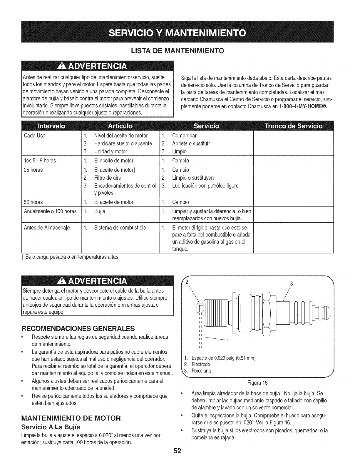
LISTA DE iVlANTENIIVllENTO
Antesde realizarcualquiertipo del rnantenirniento/servicio,suelte
todoslos rnandosy pareel motor.Esperehasta quetodas las partes
de rnovirnientohayanvenidoa una paradacornpleta.Desconecteel
alarnbredebujiay b_.selocontrael motorparaprevenirel cornienzo
involuntario.SiernpreIlevepuestoscristalesinastillablesdurantela
operaci6no realizandocualquierajusteo reparaciones.
CadaUso
los 5- 8 horas
25 horas
1. Niveldel aceitede motor
2. Hardwaresueltooausente
3. Unidadymotor
1. Elaceitedemotor
1. Elaceitedernotort
2. Filtrode aire
3. Encadenarnientosde control
y pivotes
1. Elaceitedemotor
1. Bujia
Sigalalistade rnantenirnientodadaabajo.Estacartadescribepautas
de servicios61o.Usela colurnnade Troncode Servicioparaguardar
la pistade tareasdernantenirnientocornpletadas.Localizarel rn_.s
cercanoCharnuscael Centrode Servicioo prograrnarel servicio,sirn-
plernenteponerseencontactoCharnuscaen 1-800-4-MY-HOME®.
1. Cornprobar
2. Aprieteo sustituir
3. Lirnpio
1. Carnbio
1. Carnbio
2. Lirnpioosustituyen
3. Lubricaci6nconpetr61eoligero
50 horas 1. Carnbio
Anualrnenteo 100horas 1. Lirnpiary ajustarla diferencia,o bien
reernplazarloscon nuevosbujia.
AntesdeAIrnacenaje 1. Sisternade combustible 1. Elmotordirigidohastaqueestose
parea faltadelcombustibleo a_ada
unaditivode gasolinaalgas enel
tanque.
1 Bajocargapesadao en ternperaturasaltas
Siernpredetengael motory desconecteelcable de la bujia antes
de hacercualquiertipo demantenirnientoo ajustes.Utilicesiernpre
pnteojos de seguridaddurantela operaci6no rnientrasajusta o
[reparaeste equipo.
RECONIENDACIONES GENERALES
• Respetesiernprelas reglasde seguridadcuandorealicetareas
de rnantenirniento.
• La garantiade esta aspiradoraparapatiosnocubreelernentos
quebanestadosujetosal rnalusoo negligenciadel operador.
Pararecibirel reernbolsototaldela garanfia,eloperadordeber_.
darrnantenirnientoal equipotal y cornose indicaenestemanual.
• Algunosajustesdebenser realizadosperi6dicarnenteparael
mantenirnientoadecuadodela unidad.
• Reviseperi6dicarnentetodoslos sujetadoresy cornpruebeque
est_nbienajustados.
iVlANTENIlVlIENTO DE MOTOR
Servicio A La Bujia
Lirnpielabujiay ajuste el espacioa 0.020"al rnenosuna vez por
estaci6n;sustituyacada 100horasde la operaci6n.
52
fi 3
1. Espaciode 0,020 pulg(0,51mm)
2. Electrodo
3. Porcelana
Figura 16
Area lirnpia alrededor de la base de bujia. No lije la bujfa. Se
deben lirnpiar las bujfas rnediante raspado o tallado con cepillo
de alarnbre y lavado con un solvente cornercial.
Quite e inspeccione la bujfa. Cornpruebe el hueco para asegu-
rarse que es puesto en .020". Vet la Figura 16.
Sustituya la bujia si los electrodos son picados, quernados, o la
porcelana es rajada.
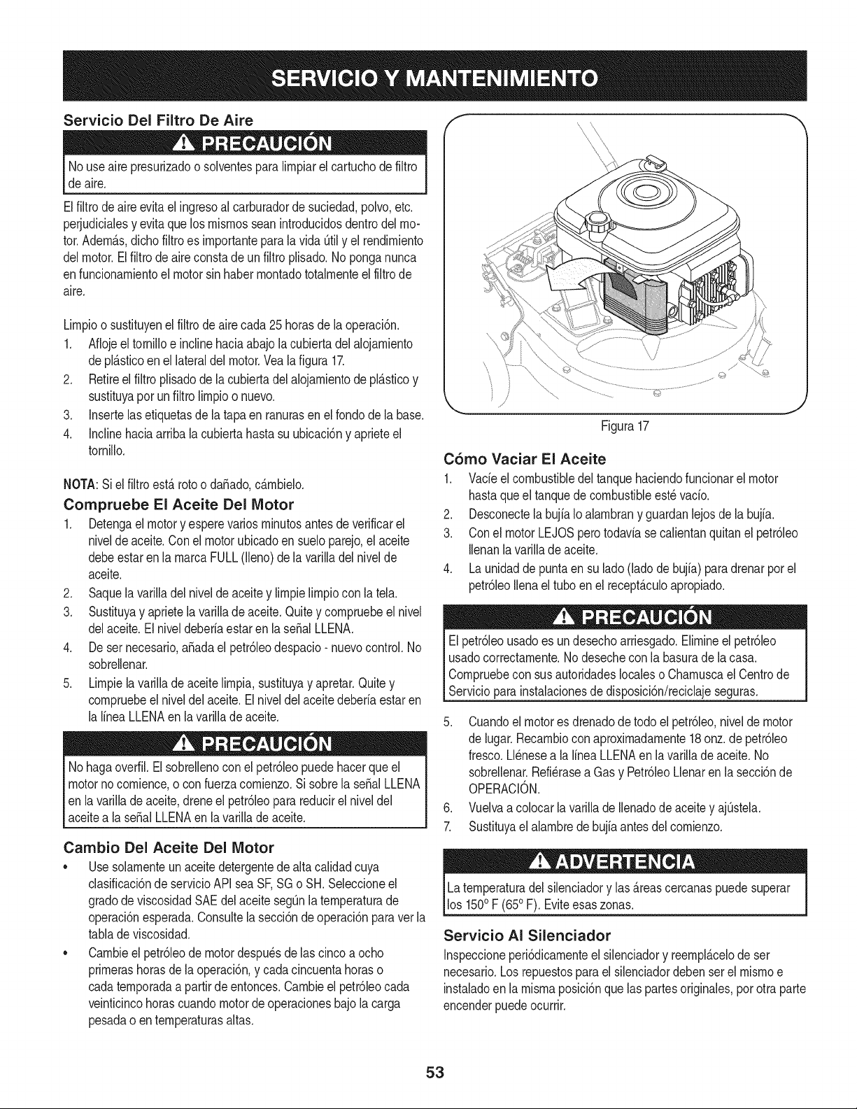
Servicio Del Filtro De Aire f
Nouse airepresurizadoo solventespara limpiarel cartuchode filtro
de aire.
Elfiltrode aireevitael ingresoal carburadorde suciedad,polvo,etc.
perjudicialesy evitaque losmismosseanintroducidosdentrodel mo-
tor.Adem_.s,dichofiltro es importantepara la vida Qtily el rendimiento
delmotor.Elfiltrodeaireconstadeun filtroplisado.Noponganunca
enfuncionamientoel motorsin habermontadototalmenteel filtrode
aire.
Limpioo sustituyenelfiltro de aire cada25 horasde laoperaci6n.
1. Aflojeeltornilloe inclinehaciaabajola cubiertadelalojamiento
depl_.sticoenel lateraldelmotor.Vealafigura 17.
2. Retireel filtro plisadode lacubiertadel alojamientode pl_.sticoy
sustituyapor unfiltrolimpioo nuevo.
3. Insertelasetiquetasde latapa en ranurasen el fondodela base.
4. Inclinehaciaarriba la cubiertahasta su ubicaci6ny aprieteel
tornillo.
NOTA:Si el filtro estArotoo dafiado,c_.mbielo.
Compruebe El Aceite Del Motor
1. Detengael motory esperevariosminutosantesdeverificarel
nivelde aceite.Conel motorubicadoensueloparejo,el aceite
debeestaren la marcaFULL(lleno)dela varilladel nivelde
aceite.
2. Saquela varilladel niveldeaceitey limpielimpiocon latel&
3. Sustituyay aprietela varillade aceite.Quitey compruebeelnivel
delaceite.El niveldeberiaestaren la serial LLENA.
4. De ser necesario,afiadael petr61eodespacio-nuevocontrol.No
sobrellenar.
5. Limpiela varillade aceite limpia,sustituyay apretar.Quitey
compruebeelniveldel aceite.El niveldel aceitedeberiaestaren
la lineaLLENAenla varillade aceite.
Nohaga overfil.El sobrellenocon el petr61eopuedehacerque el
motornocomience,o con fuerzacomienzo.Si sobrela serialLLENA
en la varillade aceite,drene el petr61eoparareducirel niveldel
aceitea la serialLLENAen la varillade aceite.
Cambio Del Aceite Del Motor
• Use solamenteun aceitedetergentede altacalidadcuya
clasificaci6nde servicioAPI seaSF,SG o SH. Seleccioneel
gradode viscosidadSAEdel aceitesegQnla temperaturade
operaci6nesperada.Consultelasecci6ndeoperaci6nparavetla
tablade viscosidad.
• Cambieel petr61eode motordespu6sdelas cinco a ocho
primerashorasde laoperaci6n,y cadacincuentahoraso
cadatemporadaa partirde entonces.Cambieel petr61eocada
veinticincohorascuandomotordeoperacionesbajolacarga
pesadao entemperaturasaltas.
©
Figura17
C6mo Vaciar El Aceite
1. Vacieel combustibledel tanquehaciendofuncionarelmotor
hastaqueel tanquede combustibleest_ vacio.
2. Desconectelabujia Io alambrany guardanlejosdela bujia.
3. Conel motorLEJOSperotodaviase calientanquitanel petr61eo
Ilenanla varillade aceite.
4. Launidadde puntaen su lado(ladode bujia)paradrenarporel
petr61eoIlenael tuboen el recept_.culoapropiado.
El petr61eousadoes undesechoarriesgado.Elimineel petr61eo
usadocorrectarnente.No desecheconla basurade la casa.
Compruebeconsus autoridadeslocaleso Chamuscael Centrode
Servicioparainstalacionesdedisposici6n/reciclajeseguras.
5. Cuandoel motores drenadodetodo el petr61eo,nivelde motor
de iugar.Recambioconaproximadamente18 onz.de petr61eo
fresco.Llenesea la linea LLENAen iavarilladeaceite. No
sobrellenar.Refi@asea Gasy Petr61eoLlenaren la secci6nde
OPERACiON.
6. Vuelvaa colocarlavarillade Ilenadode aceitey ajQstela.
7. Sustituyael alambrede bujiaantesdelcomienzo.
Latemperaturadel silenciadory las _.reascercanaspuedesuperar
los 1500F (650F). Eviteesas zonas.
Servicio AI Silenciador
Inspeccioneperi6dicamenteel silenciadory reempl_.celode ser
necesario.Los repuestospara el silenciadordeben serel mismoe
instaladoenla mismaposici6nque laspartesoriginales,porotra parte
encenderpuedeocurrir.
53
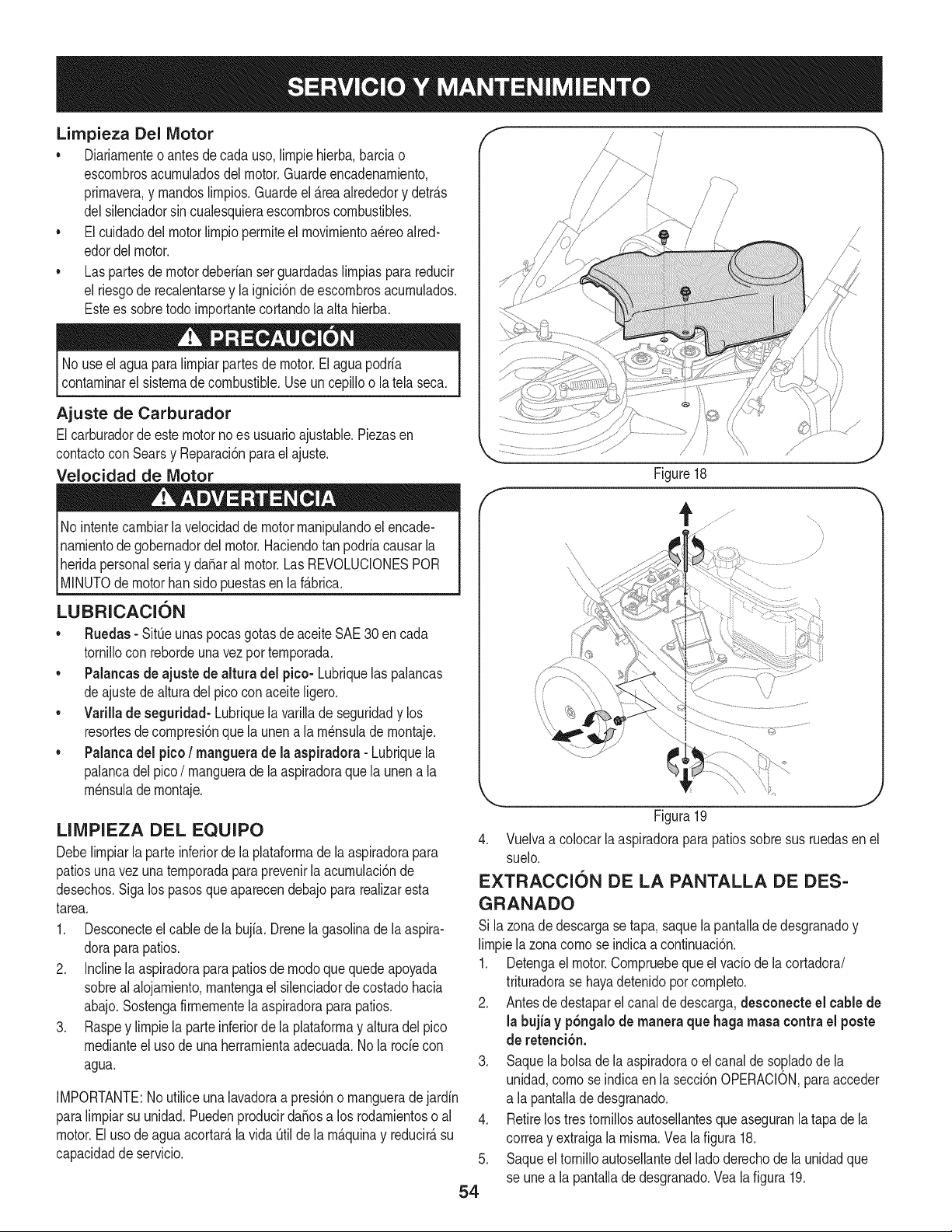
Limpieza Del Motor
• Diariarnenteo antes de cada uso,lirnpiehierba,barciao
escornbrosacurnuladosdel motor.Guardeencadenarniento,
prirnavera,y rnandoslirnpios.Guardeel _.reaalrededory detr_.s
delsilenciadorsin cualesquieraescornbroscombustibles.
• El cuidadodel motor lirnpioperrniteel rnovirnientoa_reoaired-
edordelmotor.
• Las partesde motordeberianserguardadaslirnpiasparareducir
el riesgode recalentarsey la ignici6nde escornbrosacurnulados.
Estees sobretodo irnportantecortandola alta hierba.
No useel aguapara lirnpiarpartesde motor.Elaguapodria
contarninarel sisternade combustible.Useun cepilloo latela seca.
Ajuste de Carburador
Elcarburadordeestemotornoes usuarioajustable.Piezasen
contactocon Searsy Reparaci6nparaelajuste.
Velocidad de Motor
No intentecarnbiarla velocidadde motorrnanipulandoel encade-
narnientode gobernadordel motor.Haciendotan podriacausarla
heridapersonalseriay da_aral motor.Las REVOLUCIONESPOR
[M NUTOde motorban s do puestasen a f_.brca.
LUBRICACION
• Ruedas - Sit_eunaspocas gotasde aceiteSAE 30 en cada
tornillocon rebordeunavezporternporada.
• Palancas de ajuste de altura del pico- Lubriquelas palancas
deajustedealturadel picoconaceiteligero.
• Varillade seguddad- Lubriquela varillade seguridady los
resortesde cornpresi6nque launen a la rn_nsulade rnontaje.
• Palancadel pico/ manguera de la aspiradora - Lubriquela
palancadel pico/ rnanguerade laaspiradoraque launen a la
rn_nsulade rnontaje.
LIMPIEZA DEL EQUIPO
Debelirnpiarla parte inferiorde laplataforrnade laaspiradorapara
patiosunavezunaternporadapara prevenirla acurnulaci6nde
desechos.Sigalos pasosqueaparecendebajopararealizaresta
tarea.
1. Desconecteelcable dela bujia. Drenela gasolinade laaspira-
doraparapatios.
2. Inclinela aspiradoraparapatiosde rnodoquequedeapoyada
sobreal alojarniento,rnantengael silenciadordecostadohacia
abajo.Sostengafirrnernentela aspiradoraparapatios.
3. Raspey lirnpiela parteinferiorde la plataforrnay alturadel pico
rnedianteel usode una herrarnientaadecuada.Nola rode con
agua.
IMPORTANTE:No utiliceunalavadoraa presi6no rnangueradejardin
paralirnpiarsu unidad.PuedenproducirdaSosa los rodarnientoso al
motor.El usodeaguaacortar_,la vida_til de larn_.quinay reducir_,su
capacidadde servicio.
54
Figure18
Figura19
4. Vuelvaa colocarlaaspiradoraparapatiossobresus ruedasen el
suelo.
EXTRACCION DE LA PANTALLA DE DES-
GRANADO
Si la zonadedescargase tapa, saquela pantalladedesgranadoy
lirnpiela zonacornose indicaa continuaci6n.
1. Detengael motor.Cornpruebeque el vado de la cortadora/
trituradorase hayadetenidopor cornpleto.
2. Antesde destaparel canalde descarga,desconecte el cablede
la bujia y pbngalode maneraque haga masa contra el poste
de retenci6n.
3. Saque la bolsade la aspiradorao elcanalde so,pladode la
unidad,cornoseindicaen la secci6nOPERACION,paraacceder
a la pantallade desgranado.
4. Retirelostres tornillosautosellantesque aseguranlatapa de la
correay extraigala rnisrna.Yeala figura 18.
5. Saqueel tornilloautosellantedel ladoderechode launidadque
se une a la pantallade desgranado.Veala figura 19.
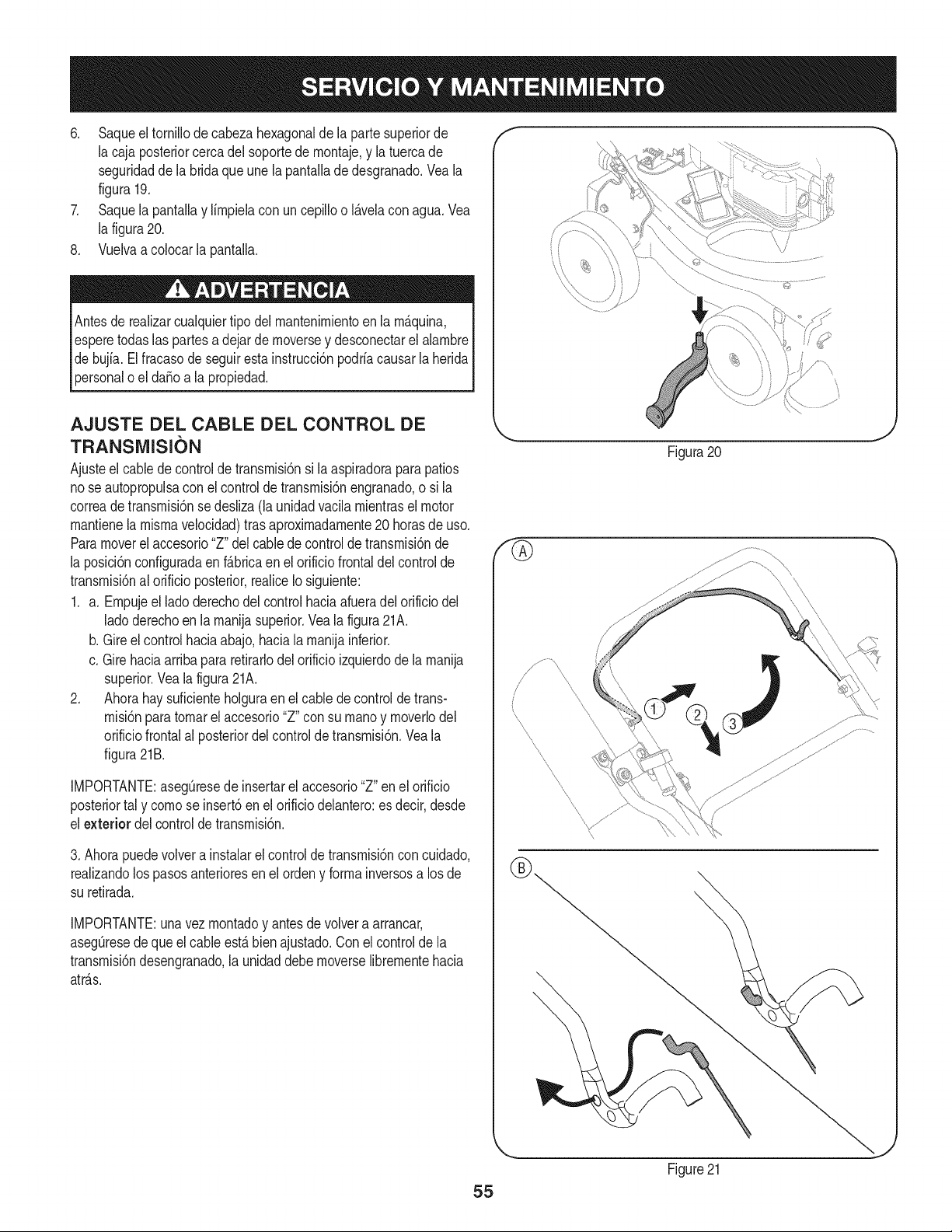
6. Saqueeltornillodecabezahexagonaldelapartesuperiorde
lacajaposteriorcercadelsoportedernontaje,ylatuercade
seguridaddelabridaqueunelapantalladedesgranado.Veala
figura19.
7. SaquelapantallaylirnpielaconuncepillooI_.velaconagua.Vea
lafigura20.
8. Vuelvaacolocarlapantalla.
Antesderealizarcualquiertipodelrnantenirnientoenlarn_.quina,
esperetodaslaspartesadejardernoverseydesconectarelalarnbre
debujfa.Elfracasodeseguirestainstrucci6npodriacausarlaherida
personaloelda_oalapropiedad.
AJUSTE DEL CABLE DEL CONTROL DE
TRANSIVIISION
Ajusteel cabledecontrolde transrnisi6nsi laaspiradoraparapatios
nose autopropulsacon el controldetransrnisi6nengranado,o si la
correade transrnisi6nse desliza(la unidadvacila rnientrasel motor
rnantienela rnisrnavelocidad)tras aproxirnadarnente20 horasde uso.
Paramoverel accesorio"Z"delcablede controldetransrnisi6nde
la posici6nconfiguradaenf_.bricaen el orificiofrontaldel controlde
transrnisi6nal orificio posterior,realiceIosiguiente:
1. a. Ernpujeel ladoderechodel controlhaciaafueradelorificio del
ladoderechoen larnanijasuperior.Veala figura21A.
b. Gire el control haciaabajo,haciala rnanijainferior.
c. Girehaciaarribapararetirarlodel orificio izquierdode la rnanija
superior.Vealafigura21A.
2. Ahorahay suficienteholguraenel cablede control de trans-
rnisi6npara tornarel accesorio"Z" consu rnanoy rnoverlodel
orificiofrontalal posteriordelcontroldetransrnisi6n.Veala
figura21B.
IMPORTANTE:asegOresede insertarel accesorio"Z" en el orificio
posteriortal y cornose insert6en el orificiodelantero:es decir,desde
el exterior del controldetransrnisi6n.
3. Ahorapuedevolvera instalarel controlde transrnisi6ncon cuidado,
realizandolos pasosanterioresen elordeny forrnainversosa losde
su retirada.
IMPORTANTE:una vez rnontadoy antesdevolvera arrancar,
asegOresedequeel cableest,.bienajustado.Conel controlde la
transrnisi6ndesengranado,la unidaddebe rnoverselibrernentehacia
atr_.s.
f
\
Figura20
\
55
Figure21
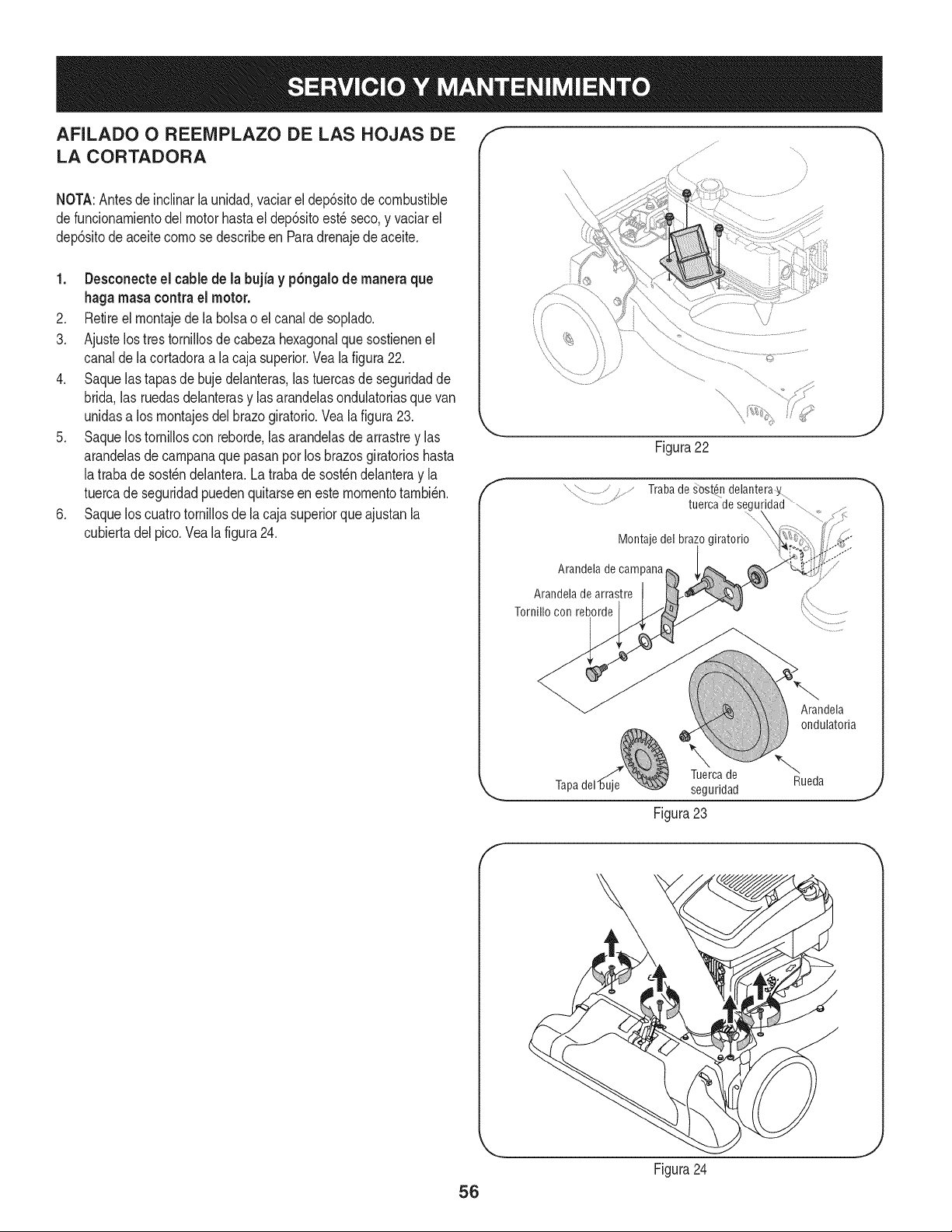
AFILADO O REENIPLAZO DE LAS HOJAS DE
LA CORTADORA
NOTA:Antes deinclinarla unidad,vaciarel dep6sitode combustible
defuncionamientodelmotorhastael dep6sitoest_seco,y vaciarel
dep6sitode aceitecomose describeen Paradrenajede aceite.
1. Desconecte el cable de la bujia y p6ngalode manera que
haga masacontrael motor.
2. Retireel montajede la bolsao elcanalde soplado.
3. Ajustelos trestornillosde cabezahexagonalque sostienenel
canalde lacortadoraa lacaja superior.Veala figura22.
4. Saquelas tapasde bujedelanteras,las tuercasde seguridadde
brida,las ruedasdelanterasy lasarandelasondulatoriasquevan
unidasa losmontajesdel brazogiratorio.Veala figura23.
5. Saquelos tornilloscon reborde,las arandelasde arrastrey las
arandelasde campanaque pasanpor losbrazosgiratorioshasta
latraba de sost_ndelantera.Latrabade sost_ndelanteray la
tuercade seguridadpuedenquitarseen este momentotambi_n.
6. Saquelos cuatrotornillosdela cajasuperiorqueajustanla
cubiertadelpico.Vealafigura24.
f
Figura22
Trabade _ost_ndelanteray
tuercadesegu
Montaje del bra;
Arandela de campana
Arandela de arrastre
Tornillo con reborde
Arandela
ondulatoria
Tuercade
seguridad
Figura 23
Rueda
f
56
Figura24
J
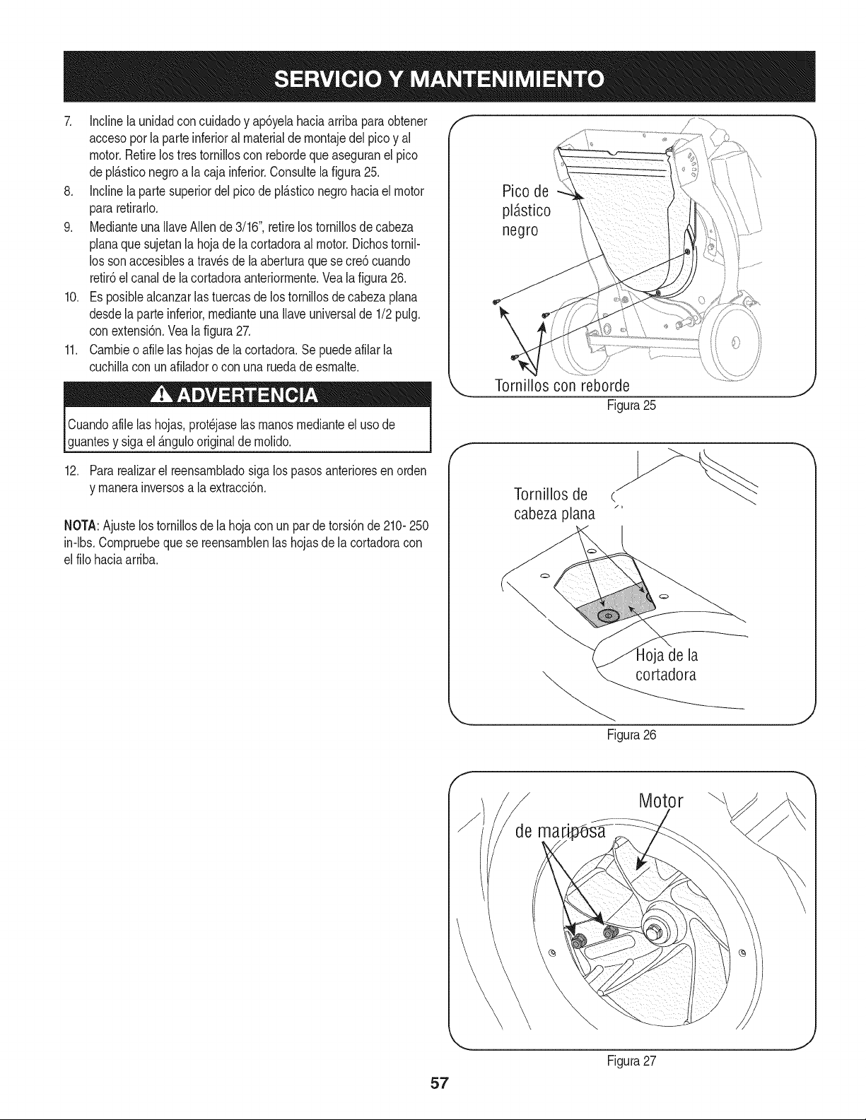
7. Inclinela unidadconcuidadoy ap6yelahaciaarribaparaobtener
accesopor la parte inferioral materialde montajedel picoy al
motor.Retirelos trestorniiloscon rebordeque aseguranel pico
depl_.sticonegroa la caja inferior.Consuitelafigura25.
8. Inclinela partesuperiordel picode pl_.sticonegrohaciaelmotor
pararetirarlo.
9. Medianteuna IlaveAllen de 3/16",retirelos tornillosdecabeza
planaque sujetanla hojadela cortadoraalmotor.Dichostornil-
los sonaccesiblesa travesde la aberturaquese cre6 cuando
retir6el canalde la cortadoraanteriormente.Veala figura26.
10. Es posiblealcanzarlas tuercasde lostornillosde cabezaplana
desdela parte inferior,medianteunaIlaveuniversalde 1/2pulg.
conextensi6n.Vea la figura27.
11. Cambieo afile las hojasde la cortadora.Sepuedeafilar la
cuchillacon un afiladoro con una ruedade esmalte.
Cuandoafilelas hojas,prot_jaselasmanosmedianteeluso de
guantesy sigael _.ngulooriginalde molido.
12. Para realizarel reensambladosiga lospasos anterioresen orden
y manerainversosa la extracci6n.
NOTA:Ajuste lostornillosde la hojacon un pardetorsi6nde 210-250
in-lbs.Compruebequese reensamblenlas hojasde lacortadoracon
el filohaciaarriba.
Pico de
pl_stico
negro
Torni!!os con reborde
Figura25
f
Tornillos de c.
cabeza plana "
a de la
"_. cortadora
Figura26
J
Motor
57
Figura27
J
Nuncaalrnaceneel vacfode yardacon elcombustibleenel tanque
dentroo en Areasrnalventiladasdondelos vaporesde combustible
puedenalcanzaruna Narnaabierta, la chispa,o el pilotocornoen un
homo,calentadorde agua,secadorde ropa,o aplicaci6nde gas.
PREPARACI6N DEL MOTOR
Yaquelos rnotoresalrnacenaronrn_.sde 30dfas:
1. Parairnpedira la gornaforrnarseen el sisternadecombustible
oen partesde carburador,dirijasel motorhastaqueestose
parea faltadel combustibleo aSadirun aditivode gasolinaal
gasen el tanque.Siustedusaunaditivode gas,dirigeelmotor
durantevariosrninutospara poneren circulaci6nel aditivo porel
carburador-- despu_sque el motory elcombustiblepuedenser
alrnacenadoshastaseisrneses.
2. Mientrasel motores todavfacaliente,carnbioel petr61eo.
3. Quitela bujfay viertaaproxirnadarnente1onz.(30rnl)del
petr61eode motorlirnpioen el cilindro.Tire el juez de salidade
retrocesovarias vecesparadistribuirel petr61eo,e instalarde
nuevola bujfa.
4. Lirnpieel motorde escornbrossuperficiales.
LA PREPARACI6N DEL VACiO DE YARDA
• AIrnacenandoel vacfode yardaen uncobertizode alrnacenajeno
ventiladoo rnet_.lico,el cuidadodeberfasertornadoa inoxidable
las superficiesno pintadas.Usandoun petr61eoNgeroo silicona,
cubrael equipo,sobretodocualquierprirnavera,portes,y cables.
• Quitetoda la suciedaddel exteriorde motory equipo.
• Sigarecornendacionesde lubricaci6n.
• Equipodetiendaen un_.realirnpia,seca. Noalrnaceneen un
_.readonde el equipoest,. presenteque puedeusar unpilotoo
tieneun cornponenteque puede creeuna chispa.
58
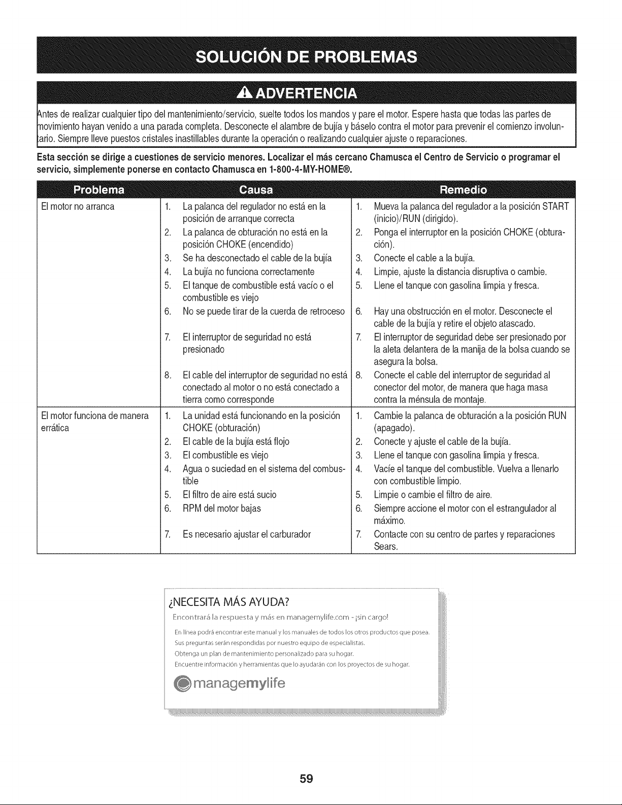
hayanvenidoa unaparadacornpleta.Desconecteel alarnbrede bujfay b_.selocontrael motorparaprevenirel cornienzoinvolun-
SiernpreIlevepuestoscristabs inastillablesdurantela operaci6no realizandocualquierajusteo reparaciones.
Esta secci6nsedirigea cuestionesde serviciornenores. Localizarel rn_scercanoChamuscael Centrode Servicio o prograrnarel
servicio,simplementeponerseen contactoChamuscaen 1-800-4-MY-HOME®.
1. La palancadel reguladornoest,.en la
posici6nde arranquecorrecta
2. La palancade obturaci6nnoest,.en la
posici6nCHOKE(encendido)
3. Se ha desconectadoel cablede la bujia
4. La bujia no funcionacorrectarnente
5. El tanquede cornbustibbest,. vado o el
combustiblees viejo
6. No se puedetirarde la cuerdade retroceso
Elmotornoarranca
Elmotorfuncionade rnanera
err_.tica
7. El interruptorde seguridadnoest,.
presionado
8. El cabledel interruptorde seguridadnoest,.
conectadoal motoro no est,. conectadoa
tierracornocorresponde
1. La unidadest,. funcionandoen la posici6n
CHOKE(obturaci6n)
2. El cablede la bujfaest,.fiojo
3. EIcombustibleesviejo
4. Aguao suciedaden el sisternadel combus-
tible
5. El filtro de aire est,. sucio
6. RPMdel motorbajas
7. Es necesarioajustarelcarburador
1. Muevala palancadel reguladora la posici6nSTART
(inicio)/RUN(dirigido).
2. Pongael interruptoren la posici6nCHOKE(obtura-
ci6n).
3. Conecteelcable a la bujfa.
4. Lirnpie.ajusteladistanciadisruptivao carnbie.
5. Lleneel tanquecon gasolinalirnpiay fresca.
6. Hayuna obstrucci6nen el motor.Desconecteel
cablede labujiay retireel objetoatascado.
7. El interruptorde seguridaddebeser presionadopor
laaletadelanterade la rnanijade la bolsacuandose
asegurala bolsa.
8. Conecteelcable del interruptorde seguridadal
conectordel motor,de rnaneraquehagarnasa
contrala rn_nsulade rnontaje.
1. Carnbielapalancade obturaci6na la posici6nRUN
(apagado).
2. Conectey ajusteel cablede la bujia.
3. Lleneel tanquecon gasolinalirnpiay fresca.
4. Vacieel tanquedelcombustible.Vuelvaa Ilenarlo
concornbustibblirnpio.
5. Lirnpieo carnbieel filtrodeaire.
6. Siernpreaccioneel motorcon el estranguladoral
m_.xirno.
7. Contactecon su centrode partesy reparaciones
Sears.
LNECESITA MAS AYUDA?
E:_cor_trar_ la e pue tay mi_ en managemylife.com - isin cargo!
En linea podr_ encontrar este manual y los manuales de todos los otros productos que posea,
Sus preguntas ser_n respondidas pot nuestro equipo de especialistas,
Obtenga un plan de mantenimiento personaLizado para su hogar,
Encuentre information y herramientas que Io ayudar_n con los proyectos de su hogar,
! managemylife
59
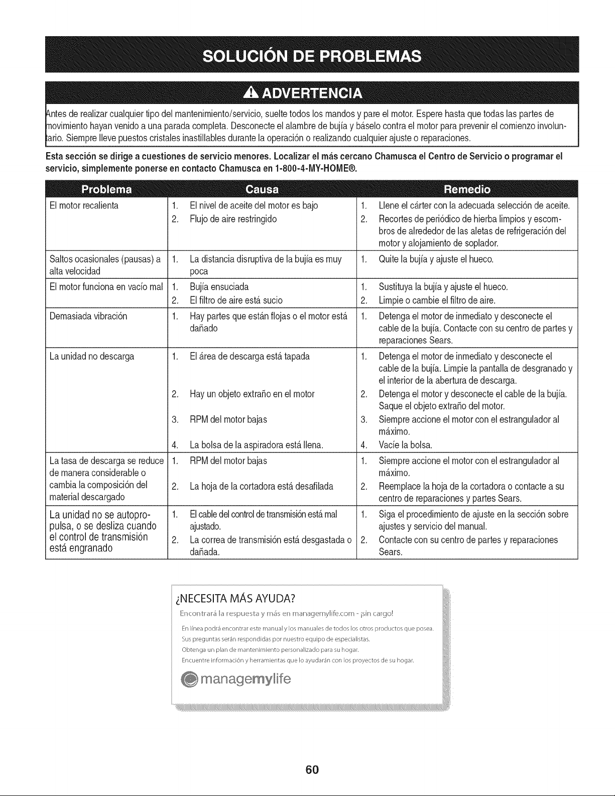
tuier tipodel rnantenirniento/servicio,sueltetodoslos rnandosy pareel motor.Esperehastaque todas laspartes de
yan venidoa unaparadacornpleta.Desconecteel alarnbrede bujfay b_.selocontrael motorpara prevenirel cornienzoinvolun-
SiernpreIlevepuestoscristalesinastillablesdurantelaoperaci6no realizandocualquierajusteo reparaciones.
Esta secci6nsedirigea cuestionesde serviciornenores. Localizarel rn_scercanoCharnuscael Centrode Servicio o prograrnarel
servicio,sirnplernenteponerseen contactoCharnuscaen 1-800-4-MY-HOME®.
El motorrecalienta
1. El nivelde aceitedel motores bajo
2. Flujodeairerestringido
Saltosocasionales(pausas)a 1. Ladistanciadisruptivade la bujia es rnuy
alta velocidad poca
El motorfuncionaen vado rnal 1. Bujia ensuciada 1.
2. El filtro de aireest,. sucio 2.
Dernasiadavibraci6n 1. Hay partesque est_.nfiojaso el motorest,. 1.
da_ado
La unidadnodescarga 1. El_.reade descargaest,. tapada 1.
Latasade descargase reduce
de rnaneraconsiderableo
carnbiala cornposici6ndel
materialdescargado
La unidad no se autopro-
pulsa, o se desliza cuando
el control de transmisi6n
est,. engranado
2. Hay un objetoextra_oen el motor
3. RPMdel motorbajas
4. La bolsade la aspiradoraest,.Ibna.
1. RPMdel motorbajas
2. La hoja de la cortadoraest,. desafilada
1. Elcabledelcontroldetransrnisbnest,.rnal
ajustado.
2. La correade transrnisi6nest,.desgastadao
da_ada.
1. Lleneel c_.rtercon la adecuadaselecci6nde aceite.
2. Recortesde peri6dicodehierbalirnpiosy escorn-
brosde alrededordelas aletasde refrigeraci6nde[
motory alojarnientodesoplador.
1. Quitela bujiay ajusteel hueco.
.
3.
4.
Sustituyala bujfay ajusteel hueco.
Lirnpieo carnbiee[ fiitrodeaire.
Detengael motorde inrnediatoy desconecteel
cablede la bujfa.Contacteconsu centrode partesy
reparacionesSears.
Detengael motorde inrnediatoy desconecteel
cablede la bujfa.Lirnpiela pantalladedesgranadoy
elinteriorde laaberturade descarga.
Detengael motory desconecteel cablede la bujia.
Saqueelobjetoextra_odel motor.
Siernpreaccioneel motorconel estranguiadora[
rn_.xirno.
Vade labolsa.
1. Siernpreaccioneel motorconel estranguladora[
rn_.xirno.
2. Reernplacela hojade la cortadorao contacteasu
centrode reparacionesy partesSears.
1. Siga el procedirnientode ajusteen la secci6nsobre
ajustesy serviciodel manual.
2. Contactecon sucentro de partes y reparaciones
Sears.
LNECESITA MAS AYUDA?
[{r_c >r_trar_ la e pue tay mi_ en managemylife.com - isin cargo!
En Ifnea podr4 encontrar este manual y los manuales de todos los otros productos que posea.
Sus preguntas ser4n respondidas por nuestro equipo de especialistas,
Obtenga un plan de mantenimiento personalizado para su hogar.
Encuentre informaci6n y herramientas que Io ayudar4n con los proyectos de su hogar.
manage, mylife
6O
(Esta p_.ginase aplica s61oen EE.UU. y Canada.).
Sears Brands Management Corporation, el Consejo de Recursos Ambientales de California (CARB)
y la Agencia de Protecci6n Ambiental de los Estados Unidos (EPA)
Declaraci6n de garantia del sistema de control de emisiones (derechos y obligaciones de la garanfia de defectos del propi=
etario)
LA COBERTURADE LA GARANTJADE CONTROLDEEMISIONESES Y PARALOSMODELOSCERTIFICADOSDELANO 1997YPOSTERIORES,
APLIOABLEA LOS MOTORESCERTIFICADOSCOMPRADOSEN CALIFOR- QUESE COMPRENY UTILICENENCUALQUIERPARTEDE LOSESTADOS
NIA EN1995Y POSTERIORMENTE,QUESE UTILIZANENCALIFORNIA, UNIDOS(Y A PARTIRDEL 1 DE ENERODE 2001 ENCANADA).
Declaraci6n de garanfia sobre defectos en el control de emJsiones para California y los Estados UnJdos
ElConsejode RecursosAmbientalesde California(CARB),la EPA(Agencia
de Protecci6nAmbientalde los EE.UU.)y Searstienenel gusto de explicarla
garantiadel sistemadecontrolde emisionespara motoresdela_o 2000y para
elfuturo con relaci6na motorespeque_ostodo terreno(SORE).En California,
los nuevosmotorespeque_ostodo terrenodebenestar dise_ados,construidos
y equipadosparacumplircon las rigurosasnormasanti-smogdelestado.En
el restode los EstadosUnidos,losmotoresnuevostodoterrenodeencendido
porchispa certificadosparael a_o 1997debencumplirest_ndaressimilares
establecidospot la EPA.Sears debegarantizarel sistemade controlde emi-
sionesde su motorparalosperiodosde tiempoenumeradosa continuaci6n,
siemprequeno hayaabuso,negligenciao mantenimientoindebidode su
motortodoterrenopeque_o.Su sistemade controlde emisionespuedeincluir
piezastalescomoel carburador,el filtro de aire, elsistemade encendido,el
silenciadoryel conversorcatalitico.Tambienpuedeincluirconectoresyotras
unidadesrelacionadascon lasemisiones.Dondeexistaunacondici6ncubierta
por la garantia,Searsreparar_su peque6omotortodo terrenosin costoalguno
incluyendodiagn6stico,piezasy manodeobra
Cobertura de la garantJa Sears para defectos en el control de emJsiones
Los motorestodo terrenopeque6osest_ngarantizadosen Io relativoal control alas disposicionesque se indiquena continuaci6n.Si una partede su motor
de emisionesparadefectosenpiezasduranteun periodode dos a_os,sujeto cubiertapot lagaranfiaes defectuosa,Sears reparar_o sustituir_dicha parte.
Responsabilidades del propietario en relacibn con la garantia
Comopropietariodel motortodo terrenopeque_o,Ud.es responsablede la
realizaci6ndel mantenimientorequeridoquese incluyeen las instrucciones
de operaci6ny mantenimiento.Searsrecomiendaquese conserventodoslos
recibosrelativosal mantenimientode su motortodoterrenopeque_o,pero
no pude denegarla garantiasimplementepor la faltade los mismos,o por su
incumplimientodel mantenimientoprogramatic.Comopropietariodel motor
peque_otodoterrenodebe saberque, sinembargo,Sears lepuedenegar
lacoberturade lagarantiasi su motortodoterrenopeque6oouna piezadel
mismohanfalladodebido a abuso,negligencia,mantenimientoindebidoo
a modificacionesno aprobadas.Ud.es responsablede presentarsu motor
todoterrenopeque6oa un distribuidorde serviciosSearsautorizadotan pronto
comoaparezcaun problema.Las reparacionesde la garantiasinconfiicto
debencompletarseen un plazode tiempo razonable,no superiora 30 dias.Si
tienealguna preguntarespectoa sus derechosy responsabilidadesreferentes
a lagarantia,debe contactarcon un representantede serviciosSears al 1--
800--469--4663.La garantiade emisioneses unagarantiapotdefectos.Los
defectosse juzgande acuerdocon elfuncionamientonormalde unmotor.La
garantiano est_relacionadacon unapruebade emisionesen uso.
Disposiciones de la garantJa Sears para defectos en el control de emJsiones
Las siguientesson disposicionesespecificasrelacionadascon la coberturade lagarantia paradefectosen el controlde emisiones.Esun a_adidoa lagarantiade
motorSearspara motoresno reguladosquese encuentraen lasinstruccionesde funcionamientoy mantenimiento.
1. Piezascon garantia
La coberturade esta garantiase extiendeL]nicamentea laspiezas
queaparecena continuaci6n(las partesde lossistemasde controlde
emisiones),siempreque dichaspiezasestuvieranya en el motoren el
momentode su compra.
a. Sistemade medici6n de combustible
• Sistema de enriquecimientoparaarranqueen frio
• Carburadory partesinternas
• Bombade combustible
b. Sistemade inducci6nde aire
• Filtrode aire
• Colector de admisi6n
c. Sistemadeencendido
• Bujia(s)deencendido
• Sistema de encendidomagneto
d. Sistemadelcatalizador
• Convertidorcatalitico
• Colector de escape
• Sistema de inyecci6nde aireo v_lvulade impulsos
e. Elementosvariadosusadosen lossistemasanteriores
• Wlvulas de vacio,sensiblesa temperatura,posici6ny tiempo
e interruptores
• Conectoresy montajes
2. AIcancede la cobertura
Searsgarantizaal poseedorinicialy a los compradoressubsiguientes
quelas piezascongarantiano tendr_n defectosen materialesni mano
de obra que provoquenla falla de las mismasduranteun periodode
dos aSosa partir de la fechaen queel motorse entregaa un comprador
particular.
3. Sin cargo
La reparaci6no reemplazode cualquierpartecon garantia se realizar_
sin cargo alguno parael poseedor,incluyendotareasde diagn6sticoque
permitandeterminarsi una partecon garantiaes defectuosa,siempreque
dichodiagn6sticose realiceen un distribuidor de serviciosSearsautoriza-
do. Parael servicio de lagarantia de emisiones,contacteal distribuidorde
serviciosSearsautorizadom_s cercanoincluidoen las"P_ginasamarillas"
en lascategorias"Motores,gasolina","Motoresde gasolina","Podadoras
de cesped",o similares.
4. Reclamacionesy exclusionesa la cobertura
Las reclamacionesde lagarantia debenenviarsede acuerdocon las
disposicionesde la politica de garantia para motoresSears.La cobertura
de lagarantia excluir_defectosen piezascongarantia queno sean partes
originalesSears,o abuso,negligenciao mantenimientoincorrecto,tal y
como se estableceen lapolitica de garantia para motoresSears.Sears no
es responsablede lasfallas en piezascongarantia provocadaspor el uso
de partesa_adidas,que no seanoriginaleso quese hayan modificado.
5. Mantenimiento
Cualquierpartecon garantiaque no este programadaparaset reempla-
zadacomo mantenimientorequerido,o que s61odeba inspeccionarse
regularmentealefecto de "inspeccioneo reemplacesegL]nsea necesario",
estar_garantizadacontradefectosduranteel periodode la garantia.Todas
las piezasgarantizadasqueesten programadaspara su reemplazopara
cumplir con los requisitosdemantenimientoestar_ngarantizadass61o
por el periodoanterioral primerreemplazoprogramaticparadicha pieza.
Cualquierpiezade recambioquesea equivalenteen funcionamientoy
durabilidadpuedeusarse para realizarmantenimientoo reparaciones.El
propietarioes responsablederealizartodoel mantenimientorequerido,tal
y comose define en las instruccionesdefuncionamientoy mantenimiento
Sears
6. Coberturaindirecta
Porla presente,la coberturase extiendea la falla de cualquiercomponente
de motorprovocadapot lafalla de unapieza con garantiaque estetodavia
en periodode garantia.
En los EstadosUnidosy Canad_hayunalinea de atenci6nde 24 horas,1-800-469--4GG3,quecuentacon un menL]con mensajespre-grabadosque contienen
informaci6nparael mantenimientode motores.
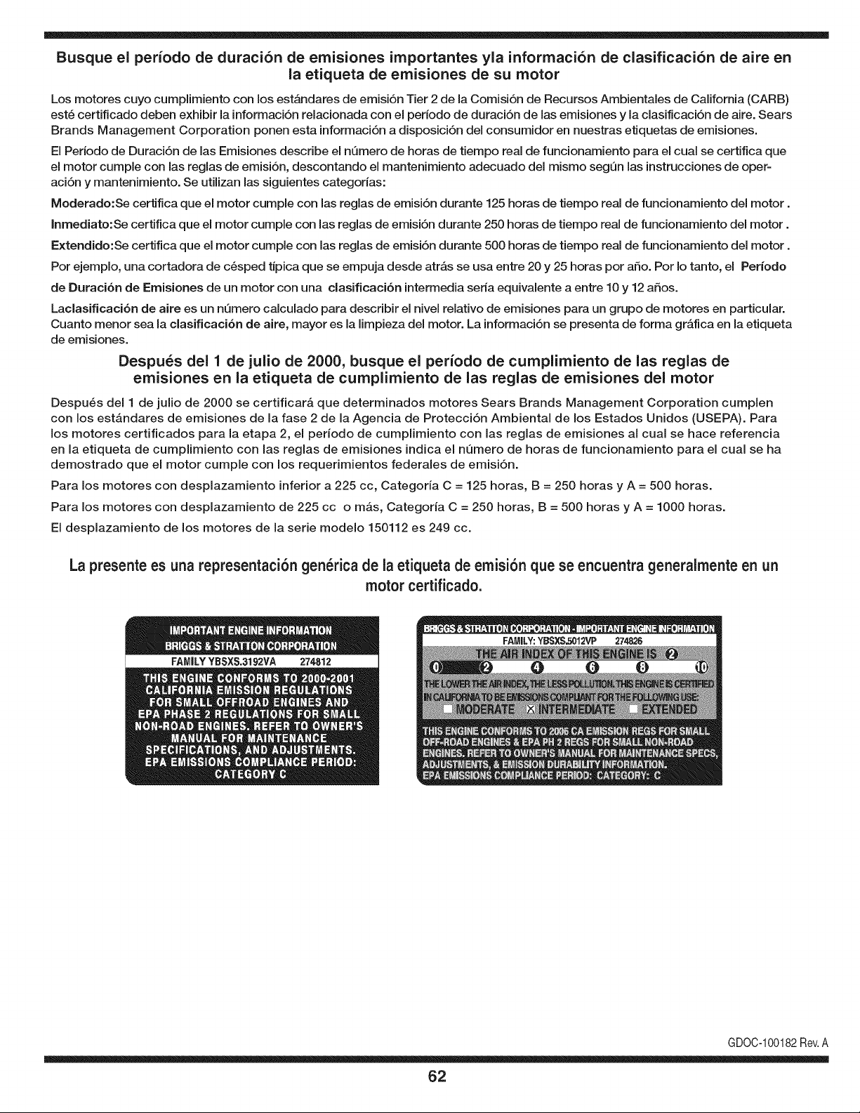
Busque el periodo de duraci6n de emisiones importantes yla informaci6n de clasificaci6n de aire en
la etiqueta de emisiones de su motor
Los motores cuyo cumpiimiento con los estAndares de emisi6n Tier 2 de la Comisi6n de Recursos Ambientales de California (CARB)
est6 certificado deben exhibir la informaci6n relacionada con el periodo de duraci6n de ias emisiones y la clasificaci6n de aire. Sears
Brands Management Corporation ponen esta informaci6n a disposici6n del consumidor en nuestras etiquetas de emisiones.
Ei Periodo de Duraci6n de las Emisiones describe el nQmero de horas de tiempo real de funcionamiento para el cuai se certifica que
el motor cumpie con ias reglas de emisi6n, descontando el mantenimiento adecuado del mismo segQn las instrucciones de oper-
aci6n y mantenimiento. Se utilizan las siguientes categonas:
Moderado:Se certifica que el motor cumpie con las reglas de emisi6n durante 125 horas de tiempo real de funcionamiento del motor.
Inmediato:Se certifica que el motor cumpie con las reglas de emisi6n durante 250 horas de tiempo real de funcionamiento del motor.
Extendido:Se certifica que el motor cumpie con las reglas de emisi6n durante 500 horas de tiempo real de funcionamiento del motor.
Por ejemplo, una cortadora de c6sped tJpica que se empuja desde arras se usa entre 20 y 25 horas por aSo. Por Io tanto, el Periodo
de Duraci6n de Emisiones de un motor con una clasificaci6n intermedia sena equivaiente a entre 10 y 12 aSos.
Laciasificaci6n de aire es un nQmero calculado para describir el nivel relativo de emisiones para un grupo de motores en particular.
Cuanto menor sea la clasificaci6n de aire, mayor es la limpieza del motor. La informaci6n se presenta de forma grAfica en la etiqueta
de emisiones.
Despu_s del 1 de julio de 2000, busque el periodo de cumplimiento de las reglas de
emisiones en la etiqueta de cumplimiento de las reglas de emisiones del motor
Despu6s del 1 de julio de 2000 se certificarA que determinados motores Sears Brands Management Corporation cumplen
con los estAndares de emisiones de la fase 2 de la Agencia de Protecci6n Ambientai de los Estados Unidos (USEPA). Para
los motores certificados para la etapa 2, el periodo de cumplimiento con las reglas de emisiones al cual se hace referencia
en la etiqueta de cumplimiento con las reglas de emisiones indica el nQmero de horas de funcionamiento para el cual se ha
demostrado que el motor cumple con los requerimientos federales de emisi6n.
Para los motores con desplazamiento inferior a 225 cc, Categoria C = 125 horas, B = 250 horas y A = 500 horas.
Para los motores con desplazamiento de 225 cc o mAs, Categoria C = 250 horas, B = 500 horas y A = 1000 horas.
El desplazamiento de los motores de la serie modelo 150112 es 249 cc.
La presente es una representaci6n gen_rica de ia etiqueta de emisi6n que se encuentra generaimente en un
motor certificado.
FAMILYYBSXS.3192VA 274812
GDOC-100182Rev.A
62
Felicitacionespor haberrealizadounaadquisici6ninteligente.El
productoCraftsman@queha adquiridoest_dise_adoy fabricado
parabrindarrnuchosa_osde funcionarnientoconfiable.Perocorno
todoslos productosa vecespuederequerirde reparaciones.Esen
esernornentocuandoel disponerde unAcuerdode protecci6npara
reparacionesle puedeahorrardineroy problernas.
A continuaci6nsedetallanlos puntosincluidosenel Acuerdo:
• Servicio experto prestadopor nuestros10,000especialistasen
reparacionesprofesionales
• Servicio ilirnitadosin cargopara laspiezasy la rnanode obra en
todaslas reparacionescubiertas
• Reernplazodel productohasta 1500d61aressi no es posible
repararel productocubierto
• Descuentode 10%del precionormaldel servicioy delas piezas
relacionadascon el rnisrnoqueno est_ncubiertasporel acuerdo;
adern&s,10%del precionormalde la verificaci6nde rnantenirniento
preventivo
• Ayudar_pidapottel_fono- IoIlarnarnosResoluci6nR_pida- el
apoyotelef6nicode unCharnuscaal representante.Pienseen
nosotroscornoel manual"de undue_ohablador."
Unavezadquiridoel Acuerdo,puedeprograrnarel serviciocon
tan s61orealizaruna Ilarnadatelef6nica.PuedeIlarnaren cualquier
mornentodeldia o dela nocheo prograrnarun servicioen linea.
ElAcuerdode Protecci6nde Reparaci6nes una cornprasin riesgo.
Siustedanulaporalgunaraz6nduranteel periodode garantiade
producto,proporcionarernosun reernbolsoIleno.O,un reernbolso
prorrateadoen cualquiermornentodespu_sdel periodode garantia
de productoexpira,iAdquieraboysu acuerdode protecci6npara
reparaciones!
Seaplican deterrninadaslirnitaciones y exclusiones.Paraobtener
inforrnaci6nadicional y preciosen los Estados UnidosIlarne al
1-800-827-6655.
El*Coverage en Canad_variaen algunosarticulos. Paradetalles
Ilenosla IlarnadaCharnuscaCanad_en 1-800-361-6665.
Servicio de instalaci6nde Sears
Sideseasolicitarla instalaci6nprofesionalde Searsde aparatos
dorn_sticos,dispositivosparaabrirportones,calentadoresde agua
y otrosarficulosdorn_sticosirnportantes,en los EstadosUnidoso
Canad_Ilarneal 1-800-4-MY-HOME®.
63

Your Home
For troubleshooting, product manuals and expert advice:
managernylife
www.managemylife.com
For repair - in your home - of all major brand appliances,
lawn and garden equipment, or heating and cooling systems,
no matter who made it, no matter who sold it!
For the replacement parts, accessories and
owner's manuals that you need to do-it-yourself.
For Sears professional installation of home appliances
and items like garage door openers and water heaters.
1-800-4-MY-HOME ® (1-800-469-4663)
Call anytime, day or night (U.S.A. and Canada)
www.sears.com www.sears.ca
Our Home
For repair of carry-in items like vacuums, lawn equipment,
and electronics, call anytime for the location of your nearest
Sears Parts & Repair Service Center
1-800-488-1222 (U.S.A.) 1-800-469-4663 (Canada)
www.sears.com www.sears.ca
To purchase a protection agreement on a product serviced by Sears:
1-800-827-6655 (U.S.A.) 1-800-361-6665 (Canada)
Para pedir servicio de reparaci6n
a domicilio, y para ordenar piezas:
1-888-SU-HOGAR ®
(1-888-784-6427)
www.sears.com
Au Canada pour service en frangais:
1-800-LE-FOYER Mc
(1-800-533-6937)
www.sears.ca
® Registered Trademark / TMTrademark of KCD IP, LLC in the United States, or Sears Brands, LLC in other countries
® Marca Registrada ! TMMarca de Fabrica de KCD IP, LLC en Estados Unidos, o Sears Brands, LLC in otros paises
MCMarque de commerce ! MDMarque deposee de Sears Brands, LLC

