Loading ...
Loading ...
Loading ...
D. ATTACHING THE BAR AND CHAIN
[CAUTION:IWear protective gloves when han-
dling or operating your saw. The chain is sharp
and can cut you even when it is not moving!
• Yoursaw Is equipped with a Reduced-Kickback
Guide Barand a Low-Kickback Chain designed to
help reduce kickback.
• Always usethe Reduced-Kickback Guide Bar and
the Low-Kickback Chain specified for your chain
saw model, when replacing these parts.
J z_ WARNING I
Do not start engine without guide bar and chain
completely assembled. Otherwlse_ the Clutcn can
come off and serious persona! inlury can result.
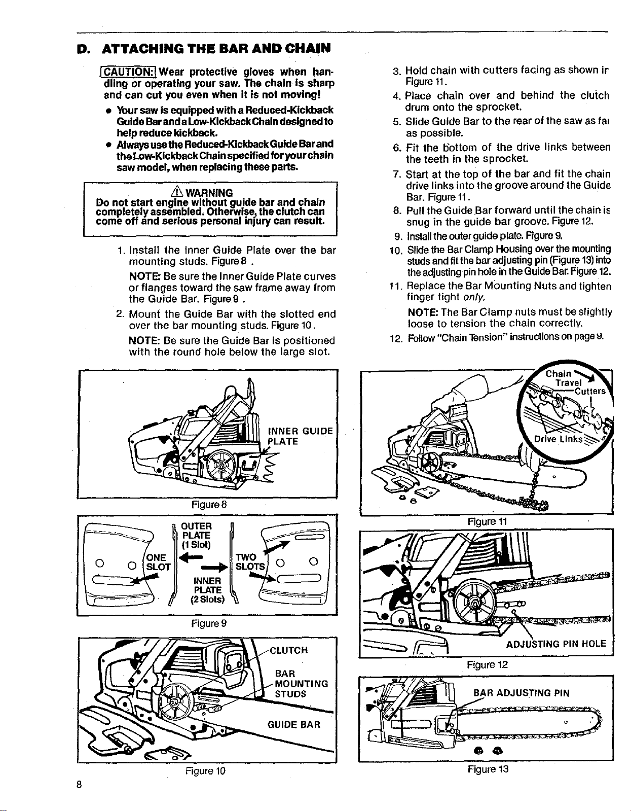
1. Install the Inner Guide Plate over the bar
mounting studs. Figure8.
NOTE: Be sure the Inner Guide Plate curves
or flanges toward the saw frame away from
the Guide Bar. Figure9.
2. Mount the Guide Bar with the slotted end
over the bar mounting studs. Figure 10.
NOTE: Be sure the Guide Bar is positioned
with the round hole below the large slot.
3. Hold chain with cutters facing as shown ir
Figure 11.
4. Place chain over and behind the clutch
drum onto the sprocket.
5. Slide Guide Bar to the rear of the saw as fal
as possible.
6. Fit the 15ottom of the drive links between
the teeth in the sprocket•
7. Start at the top of the bar and fit the chain
drive links into the groove around the Guide
Bar. Figure 11.
8• Pull the Guide Bar forward until the chain is
snug in the guide bar groove. Figure 12,
9. Installthe outer guide plate. Figure 9.
10. Slide the Bar Clamp Housing over the mounting
studs and fitthe bar adjusting pin (Figure 13)into
the adjusting pin hole in the Guide Bar.Figure 12.
11. Replace the Bar Mounting Nuts and tighten
finger tight only,
NOTE: The Bar Clamp nuts must be slightly
loose to tension the chain correctly.
12. Follow "Chain Tension" instructions on page 9.
1 INNER GUIDE
Figure8
OUTER
PLATE
(1 Slot)
INNER
PLATE
(2Slots)
wo l
;LOa_T,, 0 0
Figure9
:LUTCH
Figure 11
ADJUSTING PIN HOLE
Figure 12
BAR ADJUSTING PIN
6 6
Figure 10 Figure 13
8
Loading ...
Loading ...
Loading ...