Loading ...
Loading ...
Loading ...
LY
LIJ,/,/i
HOW TO SET UP YOUR SNOW
THROWER
® Your snow thrower is equipped with height adjust
skids (See Fig. 2) on the outside of the auger
housing. To adjust the skid height for different
conditions, see To Adjust Skid Height paragraph on
page 18.
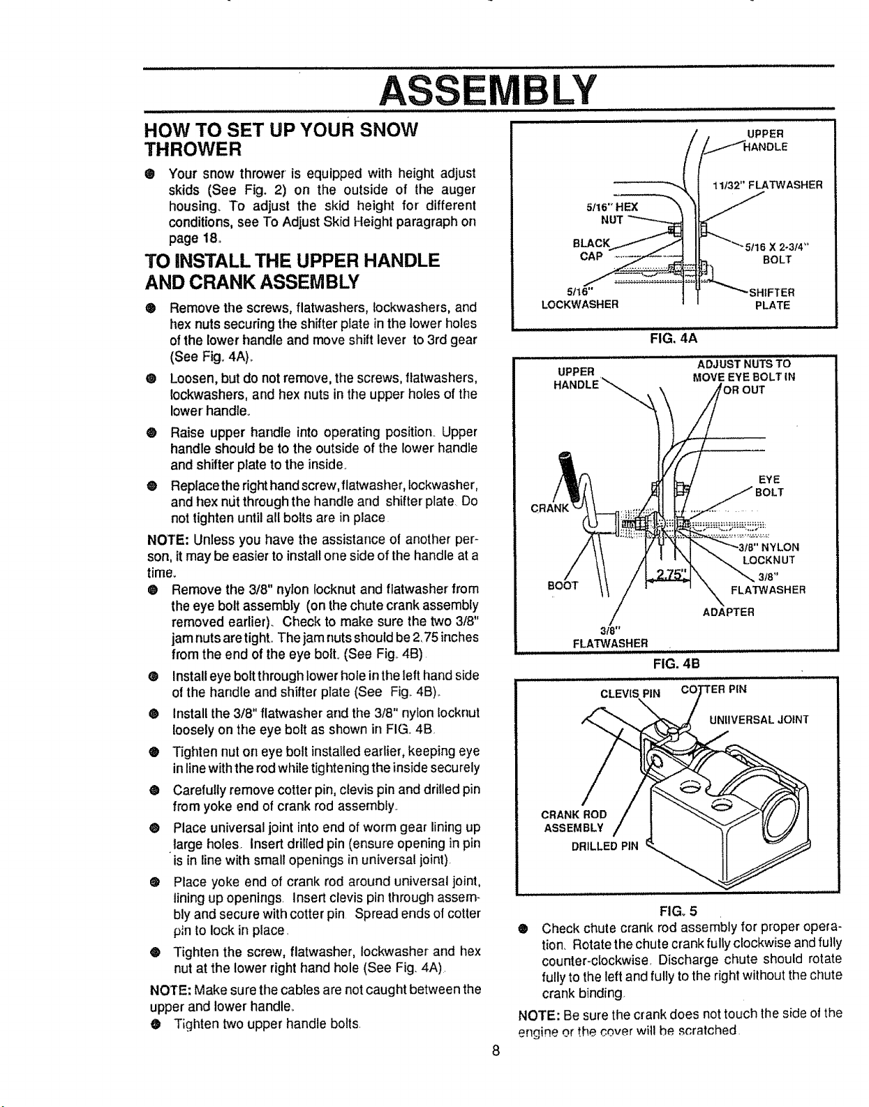
TO INSTALL THE UPPER HANDLE
AND CRANK ASSEMBLY
® Remove the screws, flatwashers, lockwashers, and
hex nuts securing the shifter plate in the lower holes
of the lower handle and move shift lever to 3rd gear
(See Fig_ 4A)_
• Loosen, but do not remove, the screws, ftatwashers,
tockwashers, and hex nuts in the upper holes of the
lower' handle.
® Raise upper handle into operating position. Upper
handle should be to the outside of the lower' handle
and shifter plate to the inside°
® Replace the right hand screw, flatwasher, iockwasher,
and hex ndt through the handle and shifter plate Do
not tighten until all bolts are in place
NOTE: Unless you have the assistance of another per-
son, it may be easier to install one side of the handle at a
tirRe_
® Remove the 3/8" nylon locknut and flatwasher from
the eye bolt assembly (on the chute crank assembly
removed earlier). Check to make sure the two 3/8"
jam nuts aretighL The jam nuts shoutd be 2,75 inches
from the end of the eye bolt, (See Fig,,4B),
® Installeye boltthroughlower hole inthe left hand side
o! the handle and shifter plate (See Fig_4B),.
@ install the 3/8" flatwasher and the 3/8" nylon Iocknut
loosely on the eye bolt as shown in FIG,, 4B
® Tighten nut on eye bolt installed earlier, keeping eye
in line with the rod while tighte ning the inside securely
• Carefully remove cotter pin, clevis pin and drilled pin
from yoke end of crank rod assembty_
• Place universal joint into end of worm gear lining up
large holes, insert drilled pin (ensure opening in pin
is in line with small openings in universal joint).
e Place yoke end of crank rod around universal joint,
lining up openings insert clevis pin through assem-
bly and secure with cotter pin Spread ends of cotter
p_nto lock in place.
® Tighten the screw, flatwasher, Iockwasher and hex
nut at the lower right hand hole (See Fig. 4A).
NOTE: Make sure the cables are not caught between the
upper and lower handler
• Tighten two upper handle bolts.
UPPER
_DLE
5Ilt
NUT
BLACK
CAP
11132" FLATWASHER
BOLT
5tt6"
LOCKWASHER PLATE
FIG, 4A
ADJUST NUTS TO
MOVE EYE BOLT IN
UPPER
HANDLE'_
EYE
BOOT
3f8"
FLA"t3t#ASHER
CLEVIS PIN
NYLON
LOCKNUT
3t8"
FLATWASHER
ADAPTER
FIG. 4B
! PIN
UNIIVERSALJOINT
CRANK ROD
ASSEMBLY
DRILLED PIN
8
FIG_5
® Check chute crank rod assembly for proper opera-
tion. Rotate the chute crank fully clockwise and fully
counter-clockwise Discharge chute should rotate
fully to the left and fully to the right without the chute
crank binding.
NOTE: Be sure the crank does not touch the side ol the
engine or the cover will he scratched
Loading ...
Loading ...
Loading ...