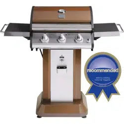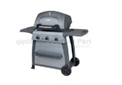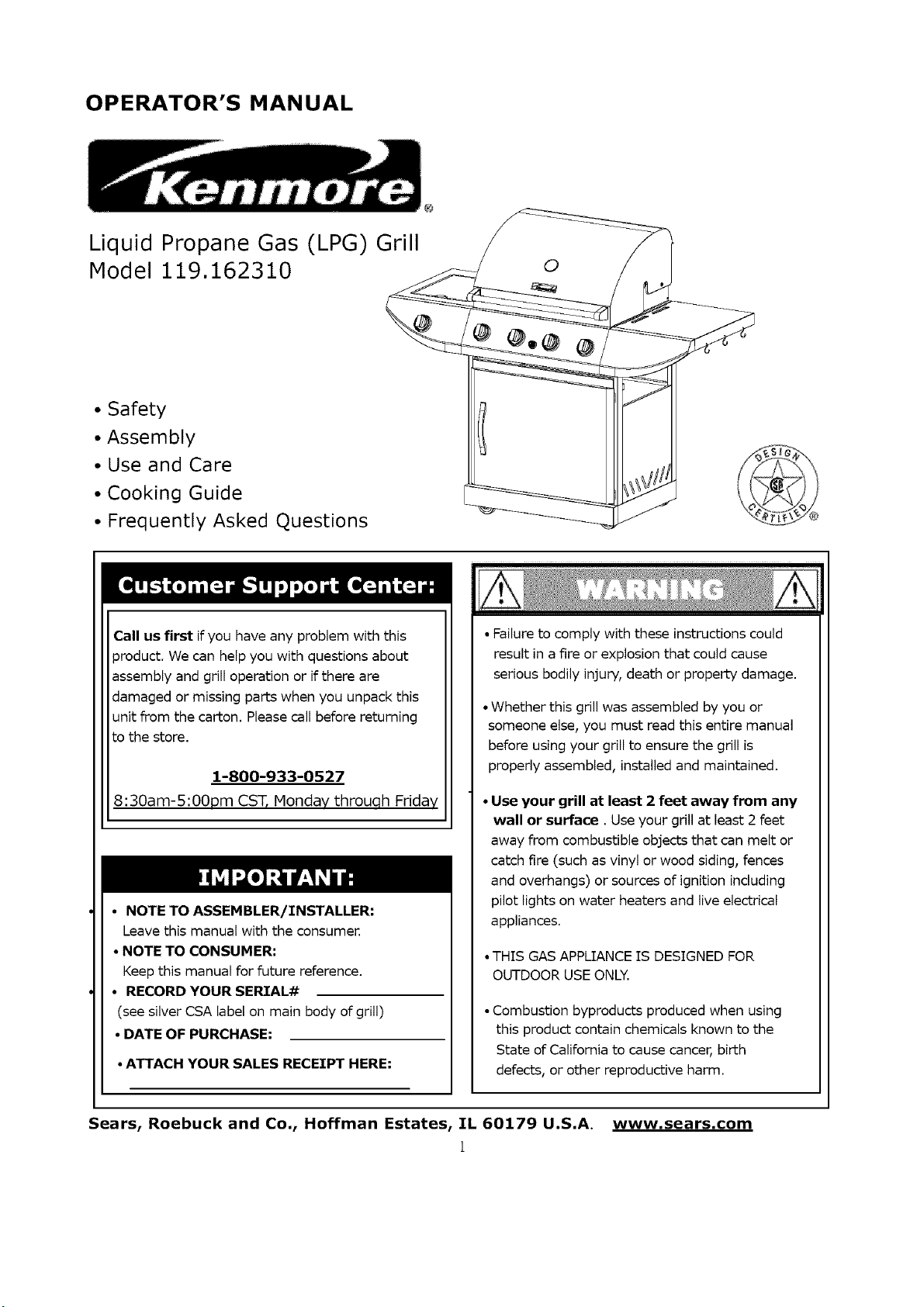
OPERATOR'S MANUAL
Liquid Propane Gas (LPG) Grill
Model 119.162310
@
• Safety
• Assembly
• Use and Care
• Cooking Guide
• Frequently Asked Questions
Call us first if you have any problem with this
product. We can help you with questions about
assembly and grill operation or if there are
damaged or missing parts when you unpack this
unit from the carton. Please call before returning
to the store.
1-800-933-0527
8:30am-5:OOpm CST, Monday throuqh Friday
• NOTE TO ASSEHBLER/INSTALLER:
Leave this manual with the consumer.
• NOTE TO CONSUHER:
Keep this manual for future reference.
• RECORD YOUR SERIAL#
(see silver CSA label on main body of grill)
• DATE OF PURCHASE:
• ATTACH YOUR SALES RECEIPT HERE:
• Failure to comply with these instructions could
result in a fire or explosion that could cause
serious bodily injury, death or property damage.
• Whether this grill was assembled by you or
someone else, you must read this entire manual
before using your grill to ensure the grill is
properly assembled, installed and maintained.
• Use your grill at least 2 feet away from any
wall or surface. Use your grill at least 2 feet
away from combustible objects that can melt or
catch fire (such as vinyl or wood siding, fences
and overhangs) or sources of ignition including
pilot lights on water heaters and live electrical
appliances.
• THIS GAS APPLIANCE IS DESIGNED FOR
OUTDOOR USE ONLY.
• Combustion byproducts produced when using
this product contain chemicals known to the
State of California to cause cancer, birth
defects, or other reproductive harm.
Sears, Roebuck and Co., Hoffman Estates, IL 60179 U.S.A. www.sears.com
1
Primary Safety Warnings ........................... 1-3
Warranty Terms and Conditions ................... 2
Pre-Assembly Instructions ............................ 3
Part Diagram and Lists ............................ 4-10
Assembly Instructions ........................... 11-19
Regulator & Hose Instructions, Gas Tank
Instructions ............................................. 20-22
Use & Care Instructions:
• Lighting Instructions .................................... 3-24
•Troubleshooting ................................................ 25
• Cleaning and Maintenance ........................26-27
• Cooking Guide ................................................... 28
• Frequently Asked Questions .....................29-30
• Sears Parts and Service Information ...........31
One-Year Full Warranty on Kenmore Grill
If this grill fails due to a defect in material or
workmanship within one year from the date of
purchase, call 1-800-4-MY-HOME® to arrange for
free repair (or replacement if repair proves
impossible).
Ten-Year Limited Warranty on Stainless
Steel Burners
For ten years from the date of purchase, any
stainless steel burner will be replaced free of
charge if it fails due to defects in material or
workmanship. You will pay any labor charges if
you wish to have it installed after the first year
from date of purchase.
Warranty Restrictions
All warranty coverage excludes igniter batteries,
grill paint loss, rusting or stainless steel
discoloration, which are either expendable parts
that can wear out from normal use in less than a
year, or are conditions that can be the result of
normal use, accident or improper maintenance.
All warranty coverage is void if this grill is ever
used for commercial or rental purposes.
All warranty coverage applies only if this grill is
used in the United States. This warranty gives you
specific legal rights, and you may have other
rights which vary from state to state.
Sears, Roebuck and Co.,
Hoffman Estates, lrL 60179
IF YOU SMELL GAS;
1. Shut off gas to the appliance.
2. Extinguish any open flame.
3. Open lid.
4. if odor continues, keep away
from the appliance and immediately
call your gas supplier or your fire
department.
1. Do not store a spare LP cylinder
within 10 feet (3m) of this appliance.
2. Do not store or use gasoline or
other flammable liquids and
vapors within 25 feet (8m) of this
appliance.
3. When cooking with oil or grease, do
not allow the oil or grease to get
hotter than 350°F (177°C).
4. Do not leave oil/grease unattended.
Grill installation Codes
The installation must conform with local codes
or, in the absence of local codes, with either the
National Fuel Gas Code, ANSI Z223.1/NFPA 54, or
CAN/CGA- B149.1, Natural Gas and Propane
Installation Code.
All electrical accessories (such as a rotisserie or
light) must be electrically grounded in accordance
with local codes, or, in the absence of local codes,
with the National Electrical Code, ANSI/NFPA 70,
or the Canadian Electrical Code, CSA C22.1.
Keep any electrical cords and/or fuel supply hoses
away from all hot surfaces.
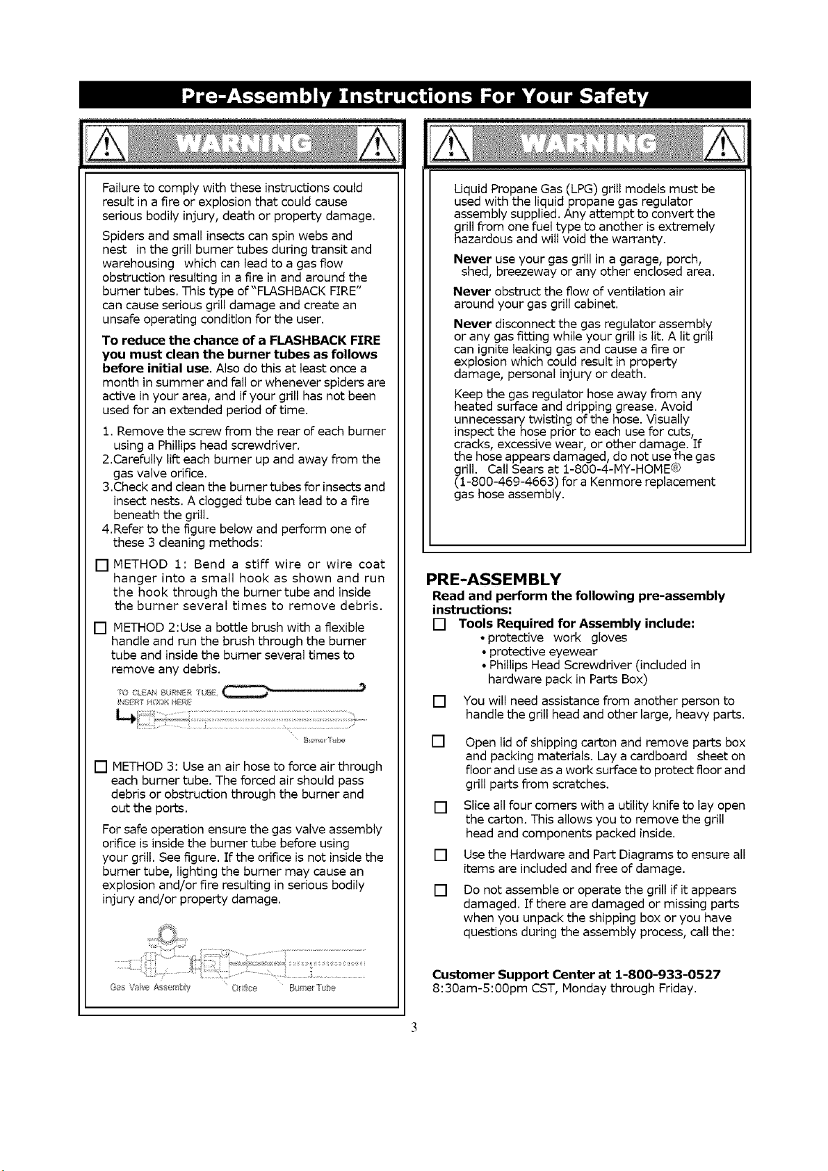
Failuretocomplywiththeseinstructionscould
resultina fire or explosion that could cause
serious bodily injury, death or property damage.
Spiders and small insects can spin webs and
nest in the grill burner tubes during transit and
warehousing which can lead to a gas flow
obstruction resulting in a fire in and around the
burner tubes. This type of "FLASHBACK FIRE"
can cause serious grill damage and create an
unsafe operating condition for the user.
To reduce the chance of a FLASHBACK FTRE
you must clean the burner tubes as follows
before initial use. Also do this at least once a
month in summer and fall or whenever spiders are
active in your area, and if your grill has not been
used for an extended period of time.
1. Remove the screw from the rear of each burner
using a Phillips head screwdriver.
2.Carefully lift each burner up and away from the
gas valve orifice.
3.Check and clean the burner tubes for insects and
insect nests. A clogged tube can lead to a fire
beneath the grill.
4.Refer to the figure below and perform one of
these 3 cleaning methods:
[] METHOD 1: Bend a stiff wire or wire coat
hanger into a small hook as shown and run
the hook through the burner tube and inside
the burner several times to remove debris.
[] METHOD 2:Use a bottle brush with a flexible
handle and run the brush through the burner
tube and inside the burner several times to
remove any debris.
[] METHOD 3: Use an air hose to force air through
each burner tube. The forced air should pass
debris or obstruction through the burner and
out the ports.
For safe operation ensure the gas valve assembly
orifice is inside the burner tube before using
your grill. See figure. If the orifice is not inside the
burner tube, lighting the burner may cause an
explosion and/or fire resulting in serious bodily
injury and/or property damage.
Uquid Propane Gas (LPG) grill models must be
used with the liquid propane gas regulator
assembly supplied. Any attempt to convert the
grill from one fuel type to another is extremely
hazardous and will void the warranty.
Never use your gas grill in a garage, porch,
shed, breezeway or any other enclosed area.
Never obstruct the flow of ventilation air
around your gas grill cabinet.
Never disconnect the gas regulator assembly
or any gas fitting while your grill is lit. A lit grill
can ignite leaking gas and cause a fire or
explosion which could result in property
damage, personal injury or death.
Keep the gas regulator hose away from any
heated surface and dripping grease. Avoid
unnecessary twisting of the hose. Visually
inspect the hose prior to each use for cuts,
cracks, excessive wear, or other damage. If
the hose appears damaged, do not use the gas
grill. Call Sears at 1-800-4-MY-HOME_
(1-800-469-4663) for a Kenmore replacement
gas hose assembly.
PRE-ASSEM BLY
Read and perform the following pre-assembly
instructions:
[] Tools Required for Assembly include:
• protective work gloves
• protective eyewear
• Phillips Head Screwdriver (included in
hardware pack in Parts Box)
[] You will need assistance from another person to
handle the grill head and other large, heavy parts.
[]
[]
[]
[]
Open lid of shipping carton and remove parts box
and packing materials. Lay a cardboard sheet on
floor and use as a work surface to protect floor and
grill parts from scratches.
Slice all four corners with a utility knife to lay open
the carton. This allows you to remove the grill
head and components packed inside.
Use the Hardware and Part Diagrams to ensure all
items are included and free of damage.
Do not assemble or operate the grill if it appears
damaged. If there are damaged or missing parts
when you unpack the shipping box or you have
questions during the assembly process, call the:
Customer Support Center at 1-800-933-0527
8:30am-S:OOpm CST, Monday through Friday.
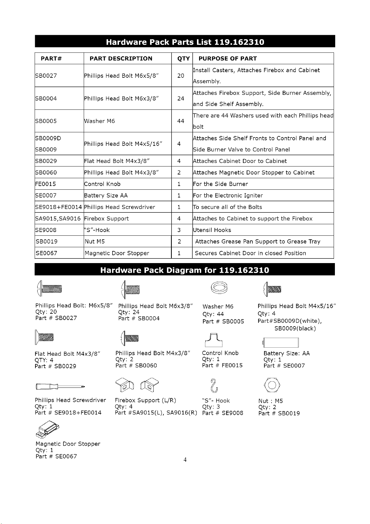
PART-#:
5B0027
SB0004
SB0005
SB0009D
SB0009
5B0029
SB0060
FE0015
SE0007
SE9018+FE0014
SA9015,SA9016
5E9008
SB0019
SE0067
PART DESCRIPTION
Phillips Head Bolt M6x5/8"
Phillips Head Bolt M6x3/8"
Washer M6
Phillips Head Bolt M4x5/16"
Flat Head Bolt M4x3/8"
Phillips Head Bolt M4x3/8"
Control Knob
Battery Size AA
Phillips Head Screwdriver
Firebox Support
"S"-Hook
Nut M5
Magnetic Door Stopper
QTY PURPOSE OF PART
Install Casters, Attaches Firebox and Cabinet
20
Assembly.
Attaches Firebox Support, Side Burner Assembly,
24
and Side Shelf Assembly.
There are 44 Washers used with each Phillips heac
44
bolt
Attaches Side Shelf Fronts to Control Panel and
4
Side Burner Valve to Control Panel
4 Attaches Cabinet Door to Cabinet
2 Attaches Magnetic Door Stopper to Cabinet
1 For the Side Burner
1 For the Electronic Igniter
1 To secure all of the Bolts
4 Attaches to Cabinet to support the Firebox
3 Utensil Hooks
2 Attaches Grease Pan Support to Grease Tray
1 Secures Cabinet Door in closed Position
Phillips Head Bolt: M6x5/8" Phillips Head Bolt M6x3/8"
Qty: 20 Qty: 24
Part # SB0027 Part # SB0004
©
Washer M6
Qty: 44
Part # SB0005
Phillips Head Bolt M4x5/16"
Qty: 4
Part#SB0009D(white),
SB0009(black)
Flat Head Bolt M4x3/8"
QTY: 4
Part # SB0029
Phillips Head Screwdriver
Qty: 1
Part # SE9018+FE0014
Magnetic Door Stopper
Qty: 1
Part # SE0067
Phillips Head Bolt M4x3/8"
Qty: 2
Part # SB0060
Control Knob
Qty : 1
Part # FE0015
Firebox Support (L/R) "S"- Hook
Qty: 4 Qty: 3
Part #SAg015(L), SAg016(R) Part # SE9008
Battery Size: AA
Qty: 1
Part # SE0007
©
Nut : MS
Qty: 2
Part # SB0019
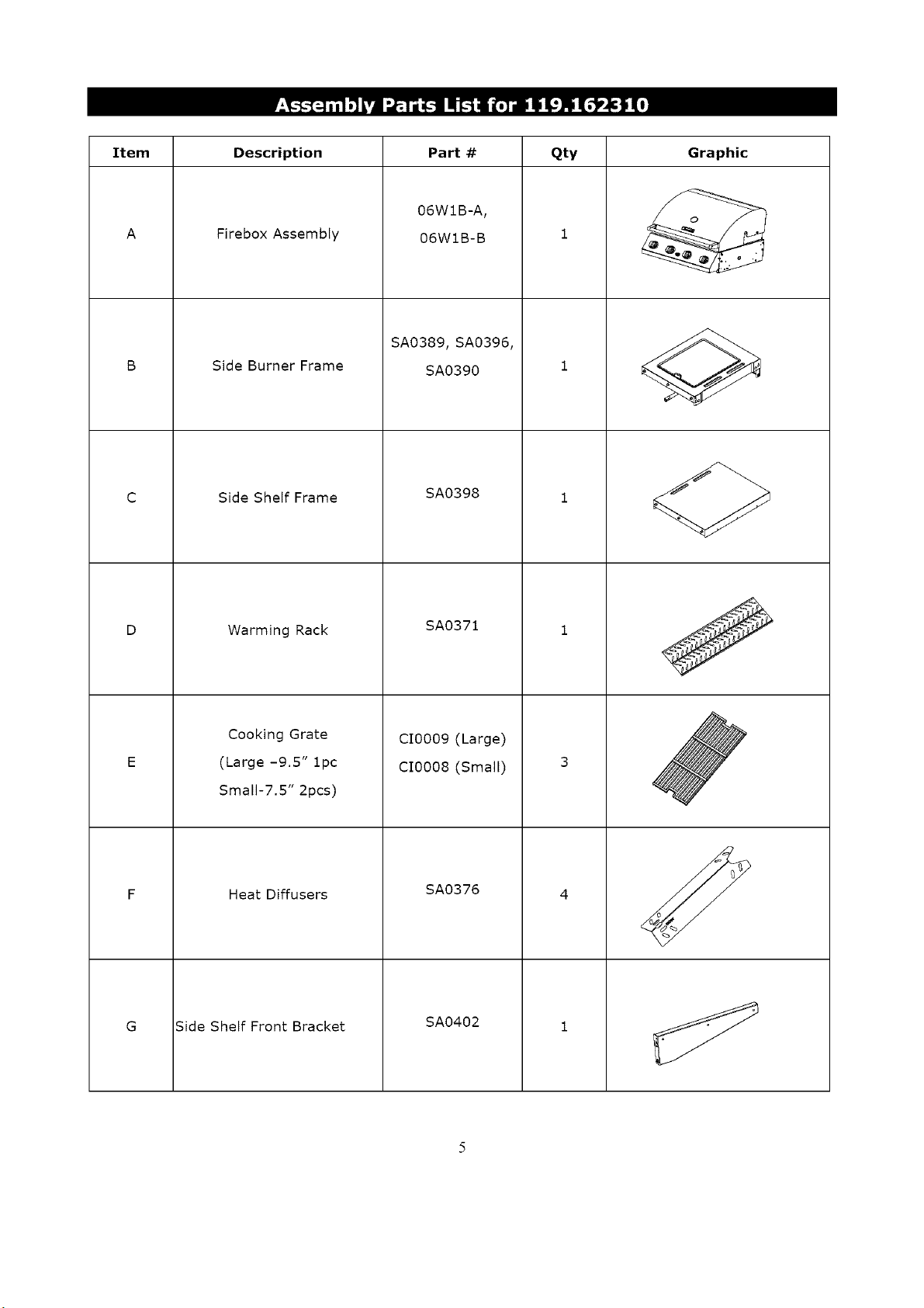
Item Description Part # Qty
Firebox Assembly
Side Burner Frame
Side Shelf Frame
Warming Rack
Cooking Grate
(Large -9.5" 1pc
Small-7.5" 2pcs)
Heat Diffusers
Side Shelf Front Bracket
06WIB-A,
06WIB-B
SA0389, SA0396,
SA0390
SA0398
SA0371
CI0009 (Large)
CI0008 (Small)
SA0376
SA0402
Graphic
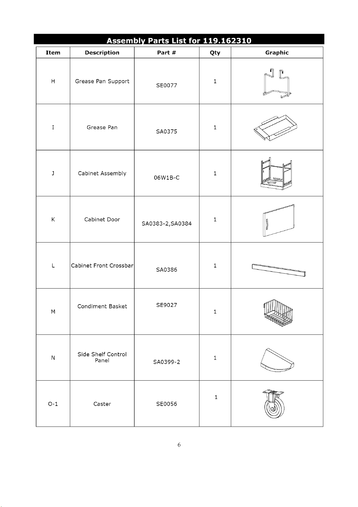
Item Description Part# Qty Graphic
0-1
Grease Pan Support
SE0077
Grease Pan
SA0375
Cabinet Assembly
Cabinet Door
Cabinet Front Crossbar
Condiment Basket
Side Shelf Control
Panel
Caster
06WIB-C
SA0383-2,SA0384
SA0386
SE9027
SA0399-2
SE0056
.J
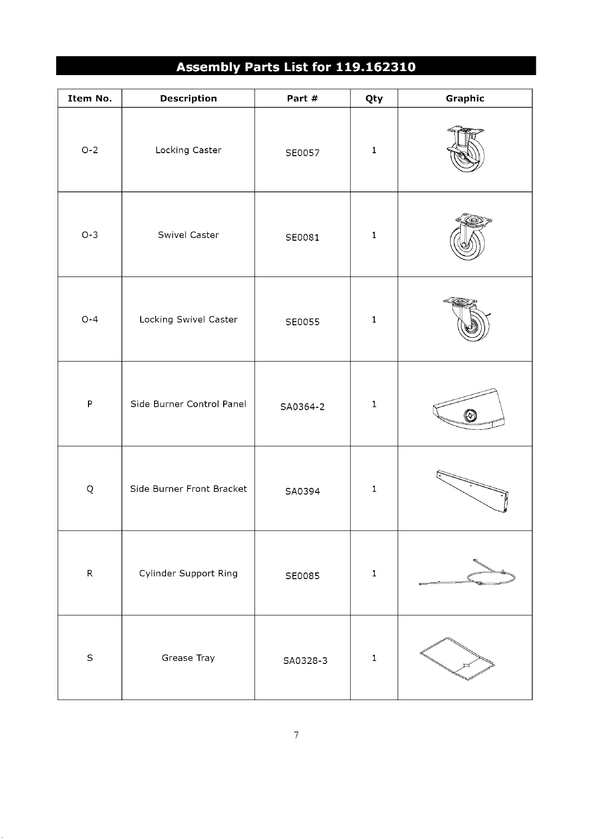
Item No. Description Part # Qty
0-2
0-3
0-4
Q
Locking Caster
Swivel Caster
SE0057
SE0081
Locking Swivel Caster
Side Burner Control Panel
Side Burner Front Bracket
Cylinder Support Ring
Grease Tray
SE0055
SA0364-2
SA0394
SE0085
SA0328-3
Graphic
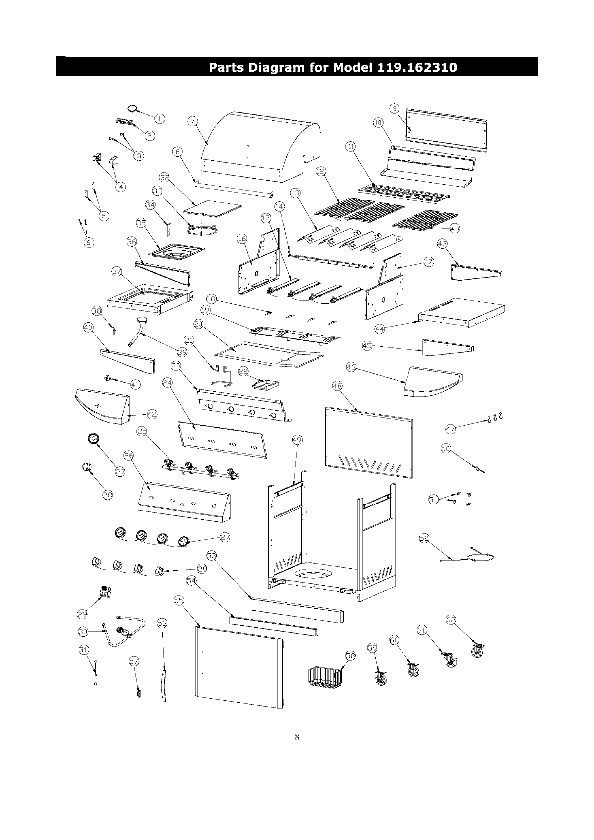
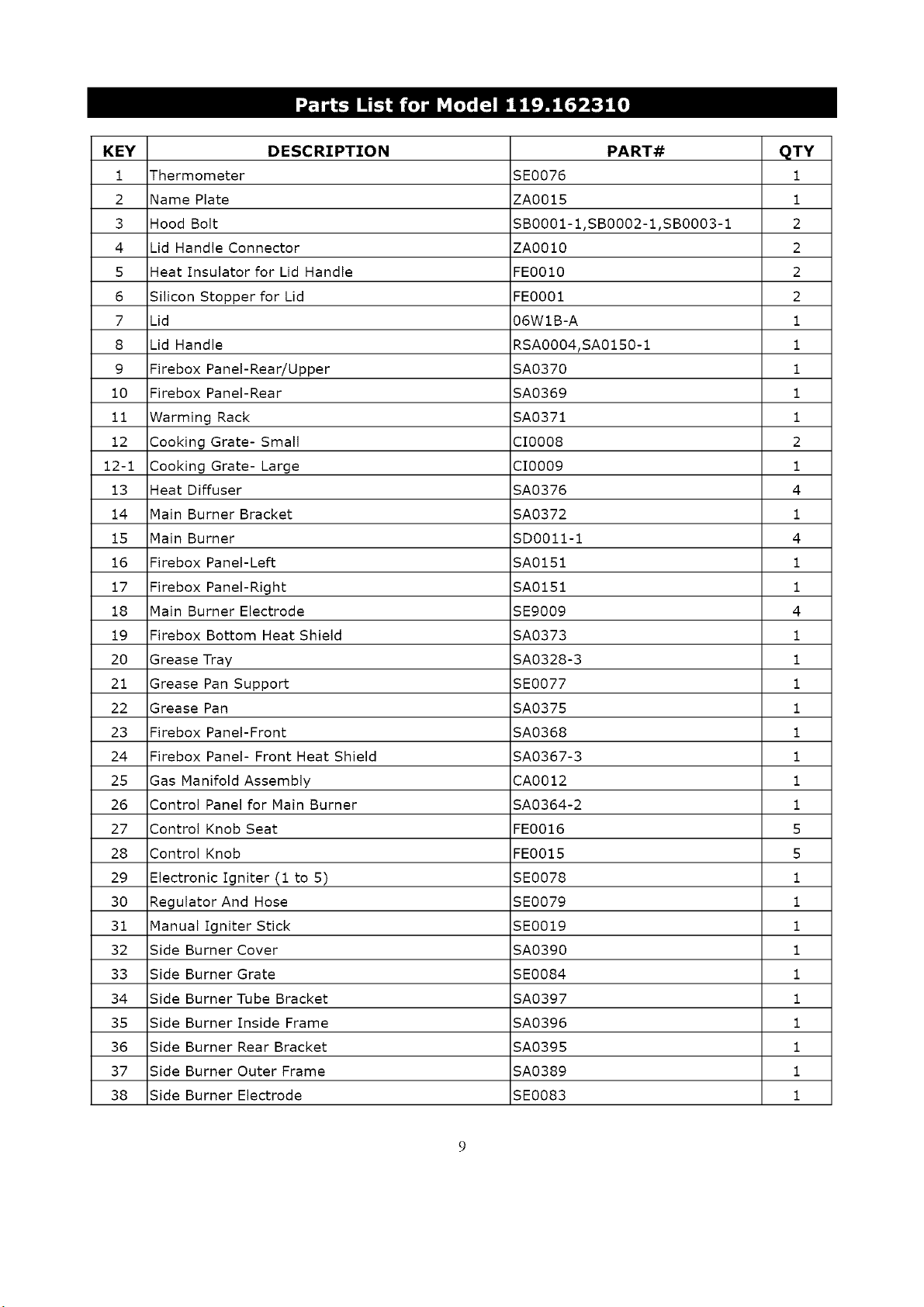
KEY DESCRIPTION PART# QTY
i Thermometer SE0076 I
2 Name Plate ZA0015 1
3 Hood Bolt SB0001-1,SB0002-1,SB0003-1 2
4 Lid Handle Connector ZA0010 2
5 Heat Insulator for Lid Handle FE0010 2
6 Silicon Stopper for Lid FE0001 2
7 Lid 06WIB-A 1
8 Lid Handle RSA0004,SA0150-1 1
9 Firebox Panel-Rear/Upper SA0370 1
10 Firebox Panel-Rear SA0369 1
11 Warming Rack SA0371 1
12 Cooking Grate- Small CI0008 2
12-1 Cooking Grate- Large CI0009 1
13 Heat Diffuser SA0376 4
14 Main Burner Bracket SA0372 1
15 Main Burner SD0011-1 4
16 Firebox Panel-Left SA0151 1
17 Firebox Panel-Right SA0151 1
18 Main Burner Electrode SE9009 4
19 Firebox Bottom Heat Shield SA0373 1
20 Grease Tray SA0328-3 1
21 Grease Pan Support SE0077 1
22 Grease Pan SA0375 1
23 Firebox Panel-Front SA0368 1
24 Firebox Panel- Front Heat Shield SA0367-3 1
25 Gas Manifold Assembly CA0012 1
26 Control Panel for Main Burner SA0364-2 1
27 Control Knob Seat FE0016 5
28 Control Knob FE0015 5
29 Electronic Igniter (1 to 5) SE0078 1
30 Regulator And Hose SE0079 1
31 Manual Igniter Stick SE0019 1
32 Side Burner Cover SA0390 1
33 Side Burner Grate SE0084 1
34 Side Burner Tube Bracket SA0397 1
35 Side Burner Inside Frame SA0396 1
36 Side Burner Rear Bracket SA0395 1
37 Side Burner Outer Frame SA0389 1
38 Side Burner Electrode SE0083 1
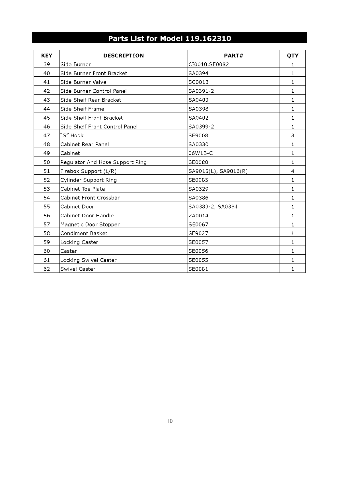
KEY DESCRIPTION PART# QTY
39 Side Burner CI0010,SE0082 1
40 Side Burner Front Bracket SA0394 1
41 Side Burner Valve SC0013 1
42 Side Burner Control Panel SA0391-2 1
43 Side Shelf Rear Bracket SA0403 1
44 Side Shelf Frame SA0398 1
45 Side Shelf Front Bracket SA0402 1
46 Side Shelf Front Control Panel SA0399-2 1
47 "S" Hook SE9008 3
48 Cabinet Rear Panel SA0330 1
49 Cabinet 06WIB-C 1
50 Regulator And Hose Support Ring SE0080 1
51 Firebox Support (L/R) SAg015(L), SAg016(R) 4
52 Cylinder Support Ring SE0085 1
53 Cabinet Toe Plate SA0329 1
54 Cabinet Front Crossbar SA0386 1
55 Cabinet Door SA0383-2, SA0384 1
56 Cabinet Door Handle ZA0014 1
57 Magnetic Door Stopper SE0067 1
58 Condiment Basket SEg027 1
59 Locking Caster SE0057 1
60 Caster SE0056 1
61 Locking Swivel Caster SE0055 1
62 Swivel Caster SE0081 1
]0
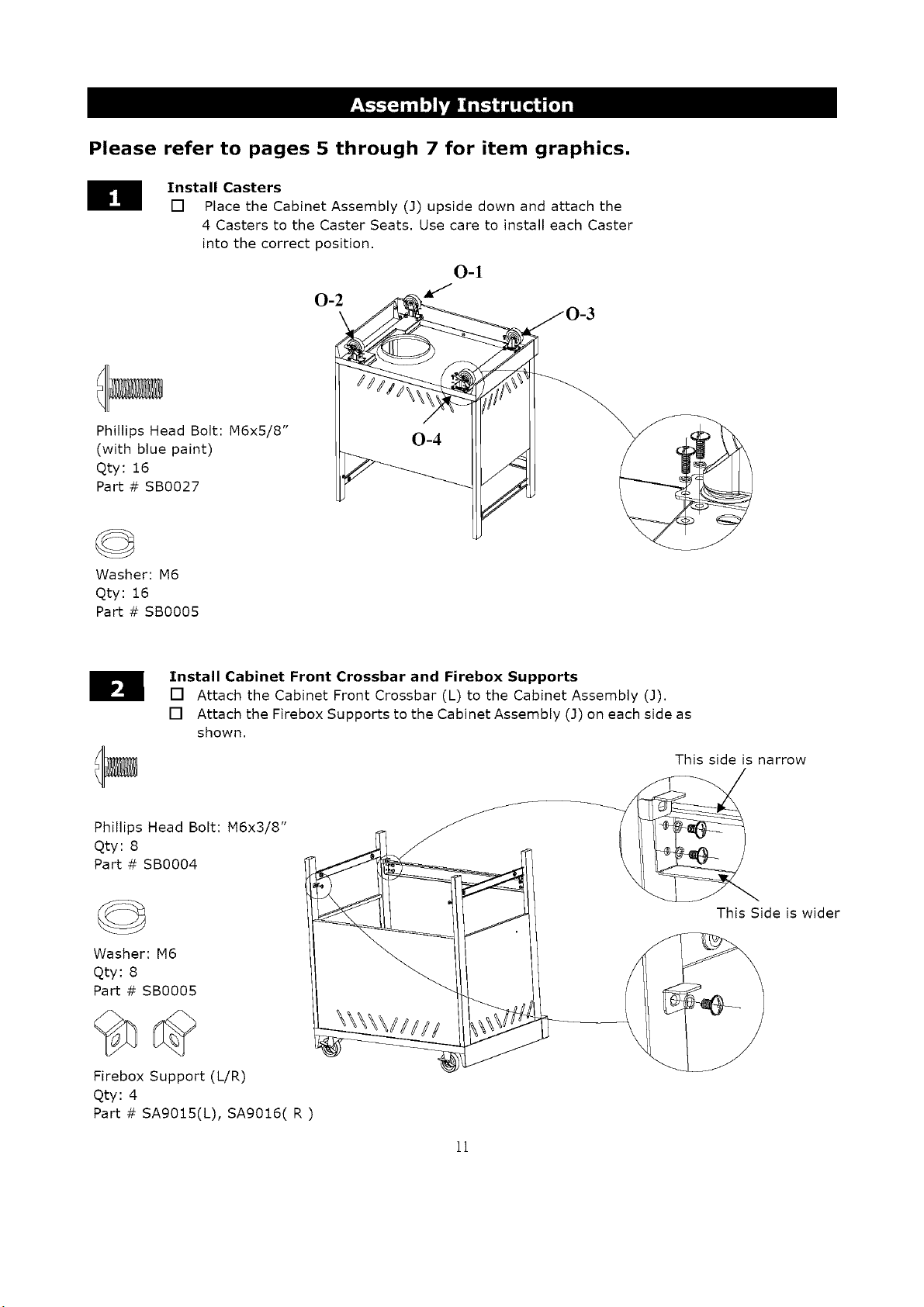
Please refer to pages 5 through 7 for item graphics.
H Install Casters
[] Place the Cabinet Assembly (J) upside down and attach the
4 Casters to the Caster Seats. Use care to install each Caster
into the correct position.
Phillips Head Bolt: N6xS/8"
(with blue paint)
Qty: 16
Part # SB0027
©
Washer: M6
Qty: 16
Part # SB0005
Install Cabinet Front Crossbar and Firebox Supports
[] Attach the Cabinet Front Crossbar (L) to the Cabinet Assembly (3).
[] Attach the Firebox Supports to the Cabinet Assembly (3) on each side as
shown.
Phillips Head Bolt: M6x3/8"
Qty: 8
Part # SBO004
Washer: M6
Qty: 8
Part # SB0005
Firebox Support (L/R)
Qty: 4
Part # SAg015(L), SA9016( R )
This side is narrow
This Side is wider
11

Attach Door, Door Stopper, and Condiment Basket to Cabinet.
[] Attach Cabinet Door (K) to the Cabinet Assembly (J) using 4 Flat Head Bolts (M4x3/8").
[] Attach Magnetic Door Stopper to the Cabinet Assembly (J) left front frame using 2 Phillips
Head Bolts (M4x3/8").
[] Hang the Condiment Basket (M) inside of the Cabinet Door (K) as shown.
Flat Head Bolt: M4x3/8"
Qty: 4
Part # SB0029
Phillips Head Bolt: M4x3/8"
Qty: 2
Part # SB0060
Magnetic Door Stopper
Qty: 1
Part # SE0067
Install Firebox Assembly to Cabinet Assembly
[] Place the Firebox Assembly (A) on the Firebox Supports.
We recommend using 2 people to lift the Firebox Assembly (A).
[] Attach the Firebox Assembly to the Cabinet Assembly using
4 Phillips Head Bolts and 4 Washers.
Phillips Heat Bolt: M6x5/8"
Qty: 4
Part # SB0027
Washer: M6
Qty: 4
Part # SB0005
]2
Install Grease Tray and Grease Pan and Grease Pan Support
[] Slide the Grease Tray (S) along two sides of Firebox Assembly from the back of the Firebox
Assembly and stopped by two screws on the two sides of the cabinet.
[] Attach Grease Pan Support (H) to the Grease Tray, using 2 M5 Nuts, as shown.
[] Install the Grease Pan (I) into the Grease Pan Support (H), inserting it from the front of the
cabinet.
©
Nut: M5
qty: 2
Part # SB0019
Install Side Burner Control Panel to Side Burner Frame
[] Attach the Side Burner Control Panel (P) and Side Burner Front Bracket (q) to the
Side Burner Frame (B), using 3 Phillips Head Bolts and 3 Washers.
Phillips Head Bolt: M6x3/8"
Qty: 3
Part # SB0004
Washer: M6
Qty: 3
Part # SBO005
]3
Install Side Burner Assembly to Firebox Assembly.
[] Loosely screw 2 Phillips Head Bolts (M6x3/8") and 2 Washers into the upper left and
right corner holes in the left side of the firebox as shown in Inset 1. Leave 1/4" of the
bolts extending out of the firebox sides to attach the side burner brackets. Slide the Side
Burner Front and Rear Brackets over the heads of those bolts and tighten.
[] Use 2 Phillips Head Bolts (M6x3/8") and 2 Washers to attach the lower holes in the Side
Burner Front and Rear Brackets to the Firebox Assembly (A) as shown in Inset 2.
Inset i
Phillips Head Bolt: M6x3/8"
Qty: 4
Part # SB0004
Washer: M6
Qty: 4
Part # SBO005
Inset 2
Secure Side Burner Assembly to the Firebox Assembly.
[] Use 1 Phillips Head Bolt and 1 Washer from inside of
the firebox to secure attached Side Burner Assembly
as shown.
Phillips Head Bolt: M6x3/8"
qty: 1
Part # SB0004
Washer: M6
qty: 1
Part # SBO005
]4
Secure Side Burner Valve to Side Burner Control Panel
[] Insert the side burner valve stem up through the hole in the Side Burner Control Panel
(P). See Inset 1.
[] Insert side burner valve stem into the side burner tube. See Inset 2.
[] Secure the side burner valve to the Side Burner Control Panel (P) using 2 Phillips Head
Bolts. Ensure the side burner valve stem is centered in the stem tube of the side burner.
If not, center it, which may involve loosening the 2 Phillips Head Bolts. See Inset 3.
Phillips Head Bolt: M4x5/16"
Qty: 2
Part # SB0009D (White)
Inset 3
Inset 2
Inset 1
Attach Side Burner Control Panel to Firebox Assembly.
[] Use 1 Phillips Head Bolt (M4xS/16") to attach the Side Burner Control Panel (P)
to the Firebox Assembly (A) as shown.
Phillips Head Bolt: M4x5/16"
Qty: 1
Part # SB0009 (Black)
15
Secure Side Burner Control Knob to Side Burner Valve Stem and attach Side Burner
Ignition Wire,
[] Push the Control Knob onto the valve stem.
[] Slide the side burner ignition wire over the side burner igniter connector.
Control Knob
Qty: 1
Part # FE0015
Install Side Shelf Assembly
[] Attach the Side Shelf Control Panel (N) and Side Shelf Front Bracket (G) to the
Side Shelf Frame (C), using 3 Phillips Head Bolts and 3 Washers.
Phillips Head Bolt: M6x3/8"
Qty: 3
Part # SB0004
Washer: M6
Qty: 3
Part # SB0005
]6
_I Install Side Shelf Assembly to Firebox Assembly.
[] Loosely screw 2 Phillips Head Bolts (MBx3/8") and 2 Washers into the upper left and right
corner holes in the right side of the firebox as shown in Inset 1. Leave 1/4" of the bolts
extending out of the firebox sides to attach the side shelf brackets. Slide the Side Shelf
Front and Rear Brackets over the heads of those bolts and tighten.
[] Use 2 Phillips Head Bolts (M6x3/8") and 2 Washers to attach the lower holes in the Side
Shelf Front and Rear Brackets to the Firebox Assembly (A) as shown in Inset 2.
[] Use 1 Phillips Head Bolt ( M4x5/16" ) to attach the Side Shelf Control Panel (N) to Firebox
Assembly (A) as shown in Inset 3.
Phillips Head Bolt: M6x3/8"
Qty: 4
Part # SBO004
Washer: M6
Qty: 4
Part # SBO005
Phillips Head Bolt: M4x5/16"
Qty: 1
Part # SBO009 (Black)
Inset 1
Inset 3
Inset 2
_1_ Secure Side Shelf Assembly to the Firebox Assembly
[] Use 1 Phillips Head Bolt and 1 Washer from inside of firebox
to secure attached Side Shelf Assembly.
Phillips Head Bolt: M6x3/8"
Qty: 1
Part # SBO004
Washer : M6
Qty: 1
Part # SBO005
]?
Place Heat Diffusers, Cooking Grates, and Warming Rack into the Firebox Assembly
[] Place the Heat Diffusers (F) into the Firebox Assembly (A). Ensure the fronts of the Heat
Diffusers, marked "FRONT", are at the front of the firebox.
[] Place the Grates (E) into the Firebox Assembly (A). Each grate has a small knob on each
corner. The knobs should rest on the front or back panels of the firebox. The 2 small
and 1 large grates can be inserted in any order.
[] Place the Warming Rack (D) into the slots along the top of the Firebox Assembly (A) as
shown.
_1_ Place LP Cylinder into the Cabinet
[] Put the Cylinder Support Ring (R) into two holes in cabinet tubes, unhook the cylinder
support ring and hold at top of cabinet.
[] Place the LP cylinder down into the tank support hole in the bottom of the cabinet. Ensure
the valve faces to the front. Wrap the cylinder support ring around the top of the tank and
hook to secure the LP cylinder in place. See Inset 1.
[] Unscrew the bolt and nut on the left side cabinet panel and attached the left side cabinet
panel to Cylinder Support Ring using the unscrew bolt and nut. See Inset 2.
Ensure the regulator hose goes through the regulator hose support ring.
Do Not Hook Up the LP Cylinder to the Regulator Assembly at this time.
Inset 1
0
Cylinder Support Ring Regulator Hose Support Ring
]8
m
Install Battery and Utensil Hooks
[] Unscrew the electronic igniter cap. Place the "AA" Battery into the igniter with the
positive (+) end up. Screw the electronic igniter cap back into place. See Inset 1.
[] Insert the small end of the "S" Hooks into the holes on the end of the Side Shelf
Frame ( C ). See Inset 2.
Battery (Size AA)
Qty: 1
Part # SE0007
o
Inset 2
"S" Hooks
qty: 3
Part # SE9008
Inset 1
Congratulations - Assembly is now Complete
[] Remove any additional labels or packing material from the grill except the CSA label.
Be sure to clean all foam packing material out of all areas.
[] Please proceed to and read the remaining sections of the Operator's Manual prior to
hooking up your LP cylinder or operating your grill.
O
@ @.@ @
]9
CORRECT LP GAS TANK USE
[] LP gas grill models are designed for use with a
standard 20 lb. (9.1kg)Liquid Propane Gas (LP
Gas) tank, which is not included with the grill.
Never connect your gas grill to an LP gas tank that
exceeds this capacity. A tank of approximately 12"
(305mm) in diameter by 18-1/2"(472mm) high is
the maximum size LP gas tank to use. You must
use an "OPD" gas tank which offers a listed Overfill
Prevention Device. This safety feature prevents
tanks from being overfilled which can cause
malfunction of the LP gas tank, regulator and grill.
[] The LP gas tank must be constructed and marked in
accordance with the Specifications for LP-Gas
Cylinders of the U.S. Department of Transportation
(D.O.T.) or the National Standard of Canada,
CAN/CSA-B339, Cylinders, Spheres and Tubes for
Transportation of Dangerous Goods; and
Commission, as applicable.
[] The LP gas tank must have a shutoff valve
terminating in a LP gas supply tank valve outlet
that is compatible with a Type 1 tank connection
device. The LP gas tank must also have a safety
relief device that has a direct connection with the
vapor space of the tank.
[] The tank supply system must have a means for
vapor withdrawal.
[] The LP gas tank used must have a collar to protect
the tank valve.
[] Never connect an unregulated LP gas tank to your
gas grill. The gas regulator assembly supplied with
your gas grill is adjusted to have an outlet pressure
of 11"water column (W.C.) for connection to an LP
gas tank. Only use the regulator and hose
assembly supplied with your gas grill.
Replacement regulators and hose assemblies
must be those specified by Sears. See the Parts
List.
[] Have your LP Gas dealer check the release valve
after every filling to ensure it remains free of
defects.
[] Always keep the LP gas tank in an upright position.
Do not subject the LP gas tank to excessive heat.
[] Never store an LP gas tank indoors. If you store
your gas grill indoors, always disconnect the LPgas tank
first and store it safely outside.
[] LP gas tanks must be stored outdoors in a
well-ventilated area and out of the reach of
children.
[] Disconnected LP gas tanks must not be stored in a
building, garage, or any other enclosed area.
[] The regulator and hose assembly can be seen after
opening the door (if applicable) and must be
inspected before each use of the grill. If there is
excessive abrasion or wear or if the hose is cut, it
must be replaced prior to using the grill again.
[] Never light your gas grill with the lid closed or
before checking to ensure the burner tubes are
fully seated over the gas valve orifices.
[] Never allow children to operate your grill. Do not
allow children or pets to play near your grill.
2O
[]
[]
Use of alcohol or drugs may impair the ability
to assemble and operate the appliance.
Keep a fire extinguisher readily accessible. In
the event of an oil or grease fire, do not attempt
to extinguish with water. Use a type B extinguisher
or smother with dirt, sand, or baking soda.
[] In the event of rain, cover the grill and turn off
the burner and gas supply.
[] Use your grill on a level, stable surface and ensure
the locking casters are locked before use.
[] Do not leave the grill unattended when in use.
[] Do not move the appliance when in use.
[] Allow the grill to cool before moving or storing.
[] Do not use your grill as a heater.
[]
This grill is not intended to be installed in or on
recreational vehicles and/or boats.
A. Do not store a spare LP gas tank under or
near this appliance.
B. Never fill the tank beyond 80 percent full;
C. If the information in "(a)"and "(b)" is not
followed exactly, a fire causing death or
serious injury may occur.
• Use your grill at least 2 feet away from
any wall or surface. Use your grill at
least 2 feet away from combustible objects
that can melt or catch fire (such as vinyl or
wood siding, fences and overhangs) or
sources of ignition including pilot lights on
water heaters and live electrical appliances.
• Never use your gas grill in a garage, porch,
shed, breezeway, or any other enclosed area.
• Never obstruct the flow of ventilation air
around your gas grill housing.
Notes about LP Gas Tank Exchange Programs
• Many retailers that sell grills offer you the option of
replacing your empty LP gas tank through an
exchange service. Use only those reputable
exchange companies that inspect, precision fill, test
and certify their tanks. Exchange your tank only for
an OPD safety feature equipped tank as described
in the LP gas tank section of this manual.
• Always keep new and exchanged LP gas tanks inan
upright position during use, transit or storage.
• Leak test new and exchanged LP gas tanks BEFORE
connecting one to your grill.
How to Leak Test your LP Gas Tank
For your safety:
• All leak tests must be repeated each time your LP gas
tank is exchanged or refilled.
• Do not smoke when checking for gas leaks.
• Do not use an open flame to check for gas leaks.
• Your grill must be leak tested outdoors in a
well-ventilated area, away from ignition sources such
as gas fired or electrical appliances. During the leak
test, keep your grill away from open flames or
sparks.
• Do not use household cleaning agents as damage to
gas assembly components can occur.
[] Use a clean paintbrush and a 50/50 mild soap and
water solution.
[] Brush soapy solution onto the LPgas tank in the areas
indicated by the arrows. See diagram.
[] If growing bubbles appear do not use or move the LP
Gas tank. Call an LP gas supplier or your fire
department.
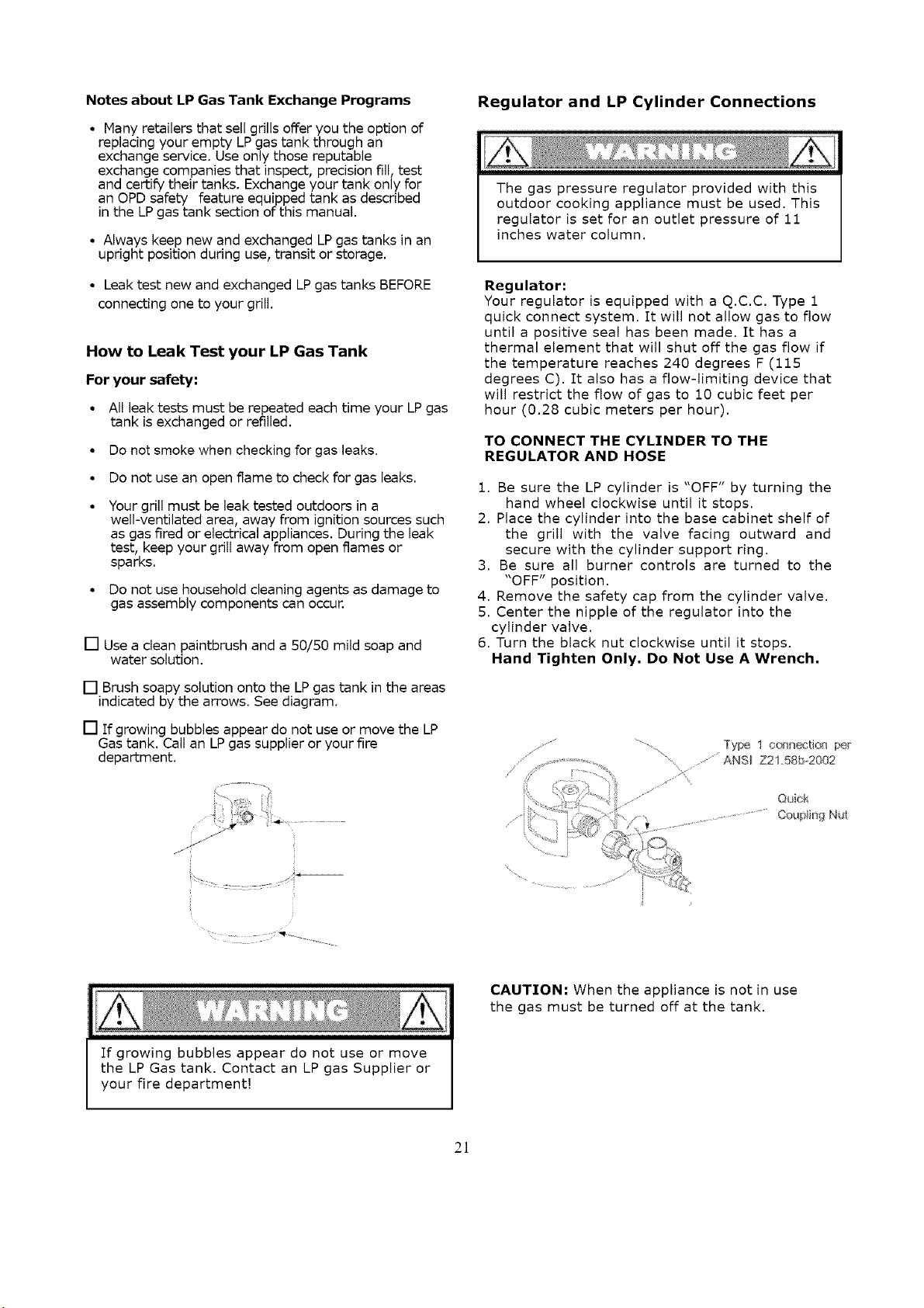
Regulator and LP Cylinder Connections
The gas pressure regulator provided with this
outdoor cooking appliance must be used. This
regulator is set for an outlet pressure of 11
inches water column.
Regulator:
Your regulator is equipped with a q.c.c. Type 1
quick connect system. It will not allow gas to flow
until a positive seal has been made. It has a
thermal element that will shut off the gas flow if
the temperature reaches 240 degrees F (115
degrees C). It also has a flow-limiting device that
will restrict the flow of gas to 10 cubic feet per
hour (0.28 cubic meters per hour).
TO CONNECT THE CYLINDER TO THE
REGULATOR AND HOSE
1. Be sure the LP cylinder is "OFF" by turning the
hand wheel clockwise until it stops.
2. Place the cylinder into the base cabinet shelf of
the grill with the valve facing outward and
secure with the cylinder support ring.
3. Be sure all burner controls are turned to the
"OFF" position.
4. Remove the safety cap from the cylinder valve.
5. Center the nipple of the regulator into the
cylinder valve.
6. Turn the black nut clockwise until it stops.
Hand Tighten Only, Do Not Use A Wrench,
',,,%
Type I onsection p_
....."ANSI Z21,58bo2002
If growing bubbles appear do not use or move
the LP Gas tank. Contact an LP gas Supplier or
your fire department!
CAUTION: When the appliance is not in use
the gas must be turned off at the tank.
21
Flow Limiting Valves on LP Gas Tanks
Your LP gas tank is equipped with a flow limiting
valve that will restrict the flow of gas due to a
sudden change in pressure. This can often activate
without your knowledge. You will notice among
other things that your grill does not get as hot as it
should, will take longer to heat up, or you may not
be able to light all burners. If you notice any of the
above, then you should reset the valve and clear
your gas line.
To do this
1. Ensure the LP gas tank valve is OFR
2. Disconnect the regulator from the LP gas
tank.
3. Open all burner control knobs including the
side burner to Hi/Light at the same time.
4. Close all burner control knobs to OFR
5. Let the LP gas tank stand for at least 10
minutes.
6. Reconnect the regulator assembly to the LP
gas tank.
7. Slowly, meaning about 1/4 turn at a time,
turn on the LP gas valve.
8. Follow the burner lighting procedures to
light the burner farthest away from the gas
source.
9. The flow limiting valve should now be reset.
This flow limiting valve is triggered by sudden
changes in pressure. This can be caused by a leak,
faulty connection of the regulator to the LP gas
tank, turning on the LP gas tank valve too quickly,
or turning the burners off by turning the LP gas
tank valve off before turning the burner control
knobs to off. Note: always turn off your burners
using the burner control knobs first before turning
the LP gas tank valve off.
Transportation and Storage
1. Place a dust cap on the cylinder valve outlet
whenever the cylinder is not in use. Only
install the type of dust cap on the cylinder
valve outlet that is provided with the
cylinder of propane valve. Other types of
caps or plugs may result in leakage.
2. Always transport your cylinder in an upright
position.
3. Do not smoke when transporting your
cylinder.
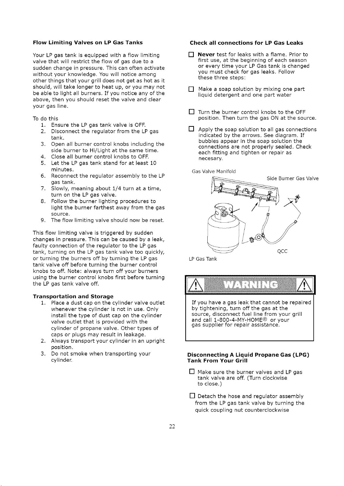
Check all connections for LP Gas Leaks
[]
Never test for leaks with a flame. Prior to
first use, at the beginning of each season
or every time your LP Gas tank is changed
you must check for gas leaks. Follow
these three steps:
[] Make a soap solution by mixing one part
liquid detergent and one part water
[]
[]
Turn the burner control knobs to the OFF
position. Then turn the gas ON at the source.
Apply the soap solution to all gas connections
indicated by the arrows. See diagram. If
bubbles appear in the soap solution the
connections are not properly sealed. Check
each fitting and tighten or repair as
necesary.
Gas Valve Manifold
Burner Gas Valve
LP Gas Tank
Ifyou have a gas leak that cannot be repaired
by tightening, turn off the gas at the
source, disconnect fuel line from your grill
and call 1-800-4-MY-HOME_; _ or your
gas supplier for repair assistance.
Disconnecting A Liquid Propane Gas (LPG)
Tank From Your Grill
[] Make sure the burner valves and LP gas
tank valve are off. (Turn clockwise
to close.)
[] Detach the hose and regulator assembly
from the LP gas tank valve by turning the
quick coupling nut counterclockwise
22
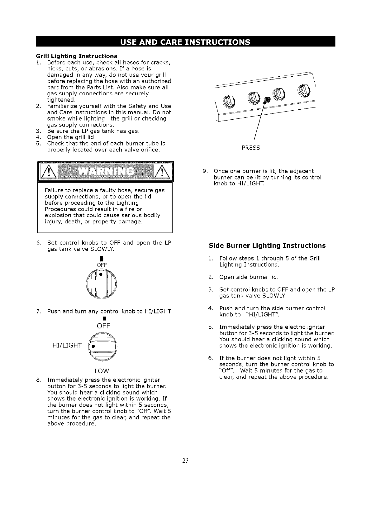
Grill Lighting Instructions
i. Before each use, check all hoses for cracks,
nicks, cuts, or abrasions. If a hose is
damaged in any way, do not use your grill
before replacing the hose with an authorized
part from the Parts List. Also make sure all
gas supply connections are securely
tightened.
2. Familiarize yourself with the Safety and Use
and Care instructions in this manual. Do not
smoke while lighting the grill or checking
gas supply connections.
3. Be sure the LP gas tank has gas.
4. Open the grill lid.
5. Check that the end of each burner tube is
properly located over each valve orifice.
PRESS
Failure to replace a faulty hose, secure gas
supply connections, or to open the lid
before proceeding to the Lighting
Procedures could result in a fire or
explosion that could cause serious bodily
injury, death, or property damage.
9. Once one burner is lit, the adjacent
burner can be lit by turning its control
knob to HI/LIGHT.
6,
7,
8,
Set control knobs to OFF and open the LP
gas tank valve SLOWLY.
I
OFF
Push and turn any control knob to HI/LIGHT
OFF
HI/LIGHT @
LOW
Immediately press the electronic igniter
button for 3-5 seconds to light the burner.
You should hear a clicking sound which
shows the electronic ignition is working. If
the burner does not light within 5 seconds,
turn the burner control knob to "Off". Wait 5
minutes for the gas to clear, and repeat the
above procedure.
Side Burner Lighting Instructions
1. Follow steps 1 through 5 of the Grill
Lighting Instructions.
2. Open side burner lid.
3. Set control knobs to OFF and open the LP
gas tank valve SLOWLY
4. Push and turn the side burner control
knob to "HI/LIGHT".
5,
6.
Immediately press the electric igniter
button for 3-5 seconds to light the burner.
You should hear a clicking sound which
shows the electronic ignition is working.
If the burner does not light within 5
seconds, turn the burner control knob to
"Off". Wait 5 minutes for the gas to
clear, and repeat the above procedure.
23
MANUALLY LIGHTING THE BURNERS WITH
THE MATCH HOLDER
I. Open the lid.
2. Ensure all burners are in the "OFF"
position.
3. Slowly turn on the gas at the LP cylinder
valve if it is not already on.
4. Place a match in the match light stick. This
is located in the inner cabinet door.
5. Use the stick to slide the lit match through
the cooking grates and the front of the heat
diffuser to the burner you wish to light.
6,
Press and turn the burner control knob to
"HI/LIGHT". Continue to push in and hold
up to 5 seconds or until the burner lights.
Ifthe burner does not light within 5
seconds, turn the burner control knob to
"OFF". Wait 5 minutes for gas to clear, and
try again.
8. When lit, turn the control knob to the
desired heat setting.
MANUALLY LIGHTING THE SIDE BURNER
1. Open the side burner cover,
2. Ensure the side burner control knob is in
the "OFF" position as well as any main
burner not in use.
3. Slowly turn on the gas if it is not already
on.
4. Strike the match, and place near the top
of the burner.
5. Turn the side burner control knob to
"HI/LIGHT"
6. If the burner does not light within 5
seconds, turn the burner control knob to
"OFF". Wait 5 minutes for the gas to
clear, and try again.
7. When lit, turn the side burner control
knob to its desired setting.
1.Do not use charcoal briquettes, lava rock, or
any type of ceramic product in this grill.
2.Do not put a barbecue cover or other flammable
material in the storage area of this grill.
Never lean over the grill cooking area while
lighting your gas grill. Keep your face and body
a safe distance (at least 18 inches) from the
lighting hole and burners when lighting your
grill with a match.
24
Troubleshooting
If the grill fails to light:
[]
[]
[]
[]
[]
[]
1,
2,
3.
Turn gas off at source and turn control knobs
to "OFF". Wait at least 5 minutes for gas to
clear, and then retry
If your grill still fails to light, check the gas
supply and connections. Ensure gas supply
is turned on (turn counterclockwise), there
is gas in the tank, and the regulator is
properly seated in the tank valve.
Repeat lighting procedure. If your grill still
fails to light, turn the gas off at the source,
turn the control knobs to "OFF", and check
the following:
Obstruction in Gas Line
Correction: Detach regulator hose assembly.
Do not smoke! Open all control knobs at the
same time to "High". Close all burner control
knobs to "OFF" and reattach the regulator hose
assembly to the grill.
Plugged Orifice or Burner Tube Obstruction
Correction: Remove burners from grill and
clean following the burner cleaning instructions
later in this manual. Observe valve orifice to be
sure there is no obstruction visible.
Ifan obstruction is suspected in Gas Valve or
Manifold, call the Customer Support Center.
Hisalignment of Igniter and Burner
Correction: Check for proper position of the
electrode tip. The gap between the electrode tip
and burner should be approximately 3/16 of an
inch. Adjust if necessary. With the gas supply off
and all control knobs set to "OFF" press the
electric igniter button and check for the
presence of a spark at the electrode.
Disconnected Electric Wires
Correction: Inspect the electric igniter (see
Parts List) found behind the control panel.
Connect loose electric wires to ignition
assembly.
Weak AA Battery
Correction: Unscrew the igniter cap and replace
the battery.
Do not dispose of batteries in fire! Batteries ma'
explode or leak.
[]
If the grill still does not light you may need to
reset the flow limiting valve in your LP tank.
Note: This procedure should be done every
time a new LP gas tank is connected to your
grill.
Follow the steps below to reset the flow
limiting device,
[] Turn LP gas tank valve "OFF".
[] Disconnect the regulator assembly from LP
Gas tank.
[] Open all burner control knobs to
"HI/LIGHT" at the same time.
[] Close all burner control knobs to "OFF"
[] Let the LP Gas tank stand for at least 10
minutes.
[] Reconnect the regulator assembly to the LP
Gas tank.
[] Slowly turn on the LP Gas tank valve.
[] Follow the burner lighting procedures to
light the burner farthest away from the gas
source.
Should a FLASHBACK fire occur in or around
the burner tubes, follow the instructions
below. Failure to comply with these
instructions could result in a fire or explosion
that could cause serious bodily injury, death,
or property damage.
• Shut off gas supply (turn the LP tank valve
clockwise) to the gas grill.
• Turn the control knobs to the "OFF" position.
• Open the grill lid.
Put out any flame with a Class B Fire
extinguisher
• Once the grill has cooled down, clean the
burner tubes and burners according to the
cleaning instructions in this Operator's
Manual.
Customer Support Center
Call 8:30 AM to 5:00 pIv] CST 1-800-933-0527 Monday through Friday,
25
Proper care and maintenance will keep your grill in
good operating condition and prolong its life. Follow
these cleaning procedures on a timely basis and your
grill will stay clean and operate with minimum effort.
CAUTION: Be sure your grill is off and cool before
cleaning, and always wear protective gloves when
cleaning your grill
Cleaning The Cooking Grates
Wash your cooking grates in a mild soap and
warm water solution. You can use a wash cloth,
vegetable brush, or brass bristled brush. Never
use any type of steel bristled brush. Dry them
when finished.
Cleaning the Heat Diffusers
Wash the heat diffusers periodically in a soap
and warm water solution. Use a vegetable brush
to remove stubborn burnt-on cooking residue.
Dry the heat diffusers thoroughly before you
reinstall them into the firebox.
Cleaning the Grease Tray and Pan
To reduce the chance of fire, the grease tray and
grease pan should be visually inspected before
each grill use. Remove any grease and wash
both with a mild soap and warm water solution.
Cleaning the Inside of the Grill Lid
Grease can have a tendency to build up on the
inside of the grill lid and could drip onto the deck
or patio when the lid is opened. Visually inspect
the inside of the grill lid before each grill use.
Remove any grease and wash with a mild soap
and warm water solution.
Annual Cleaning of the Grill Interior
Burning-off excess food after every cookout will
keep it ready for instant use. We recommend you
periodically give the entire grill a thorough
cleaning to minimize your risk of grease fire and
keep the grill in good shape. Follow these steps:
1. Turn all burner valves to the "OFF" position.
2. Turn the LP gas tank valve to the "OFF"
position.
3. Disconnect the regulator assembly from the
gas tank. Inspect the hose for cracking, cuts
or any other damage, and replace as
necessary. Refer to the Parts List in this
Operator's Manual.
4. Remove and clean the cooking grates, heat
diffusers, warming rack, burners, and grease
tray.
5. Cover each gas valve orifice with aluminum
foil.
6. Brush the inside and bottom of the grill with
a fiber pad or nylon brush and wash with a
mild soap and warm water solution. Rinse
thoroughly and let dry.
7. Remove aluminum foil from orifices and
check each orifice for obstruction.
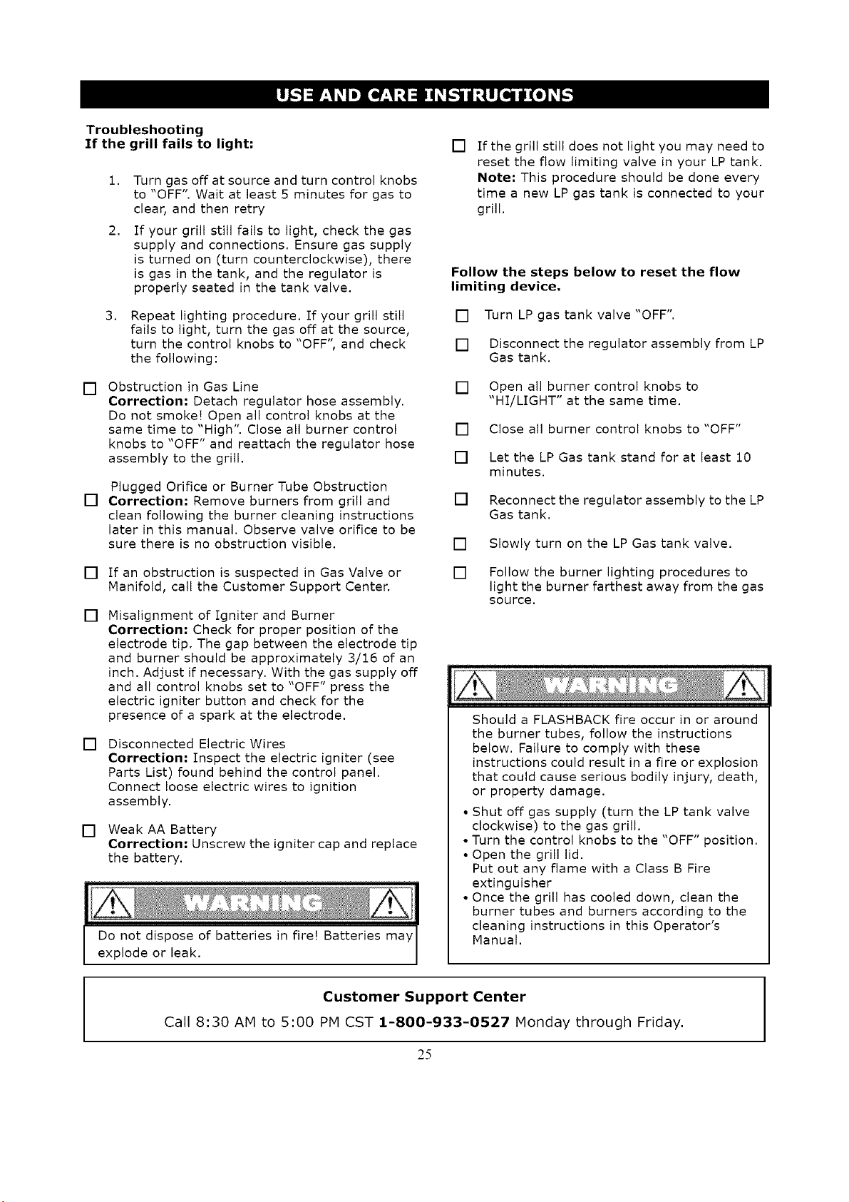
8. Replace the burners, ensuring the burners fit
down over each valve orifice.
9. Check and clean each electrode tip.
Adjust the spacing between the tips and
the burner as necessary. The space
between the electrode tip and burner
should be approximately 3/16".
10. Replace the heat diffusers, grates,
warming rack, and grease tray.
11. Reconnect the gas source and observe
the burner flame for correct operation.
Cleaning Exterior Surfaces:
Cleaning Exterior Surfaces:
Wash with a mild dish soap and warm
water solution. A cloth, soft brush, or
plastic cleaning pad can be used. Rinse
thoroughly and wipe dry.
Cleaning Exterior Stainless Steel Surfaces:
Wash with a mild dish soap and warm
water solution. Clean and polish with a
stainless steel cleaner. There are many
good quality stainless steel cleaners and
polishes available. Follow the
manufacturer's directions. Always polish
in the direction of the lines. Do not allow
dirt and grease to accumulate. Do not use
steel wool as it will scratch the surface. Do
not use abrasive cleaners and scrubbers.
CAUTION:
Heat, weathering, machine oils used in the
manufacturing of stainless steel, and dirt
can all cause exterior stainless steel
surfaces to turn tan in color. In addition,
the following products and naturally
occurring substances in the outdoors will
damage all stainless steel finishes. Use
caution so they will not come in contact
with your grill. Immediately wash them
off and dry the stainless steel should they
ever come in contact with your gas grill.
They include, but are not limited to, pool
chemicals (chlorine and bromine), lawn
fertilizer, ice melting salts, sea or salt
water, urine, bird droppings, and tree sap.
Failure to comply with these instructions may
result in a hazardous situation which, if not
avoided, may result in injury.
Keep grill area clear and free from
combustible materials, gasoline and other
flammable vapors and liquids.
Do not obstruct the flow of air for combustion
and ventilation.
Keep the ventilation openings of the tank
enclosure cabinet free and clear of debris.
26
To reduce the chance of FLASHBACK FIRE you
must clean the burner tubes as follows
periodically in summer and fall, wherever
spiders are active in your area, and if your grill
has not been used for an extended period of
time.
I. Turn all burner control knobs to the "OFF"
position.
2. Turn the LP gas tank valve to the "OFF"
position.
3. Disconnect the LP gas regulator assembly
from the LP gas tank.
4. Remove the cooking grates, heat tents,
grease cup, and grease tray from the grill.
5. Remove the screw from the rear of each
burner using a Phillips head screwdriver.
6. Carefully lift each burner up and away from
the gas valve orifice.
7. Check and clean burner tubes for insects and
insect nests. A clogged tube can lead to a fire
beneath the grill.
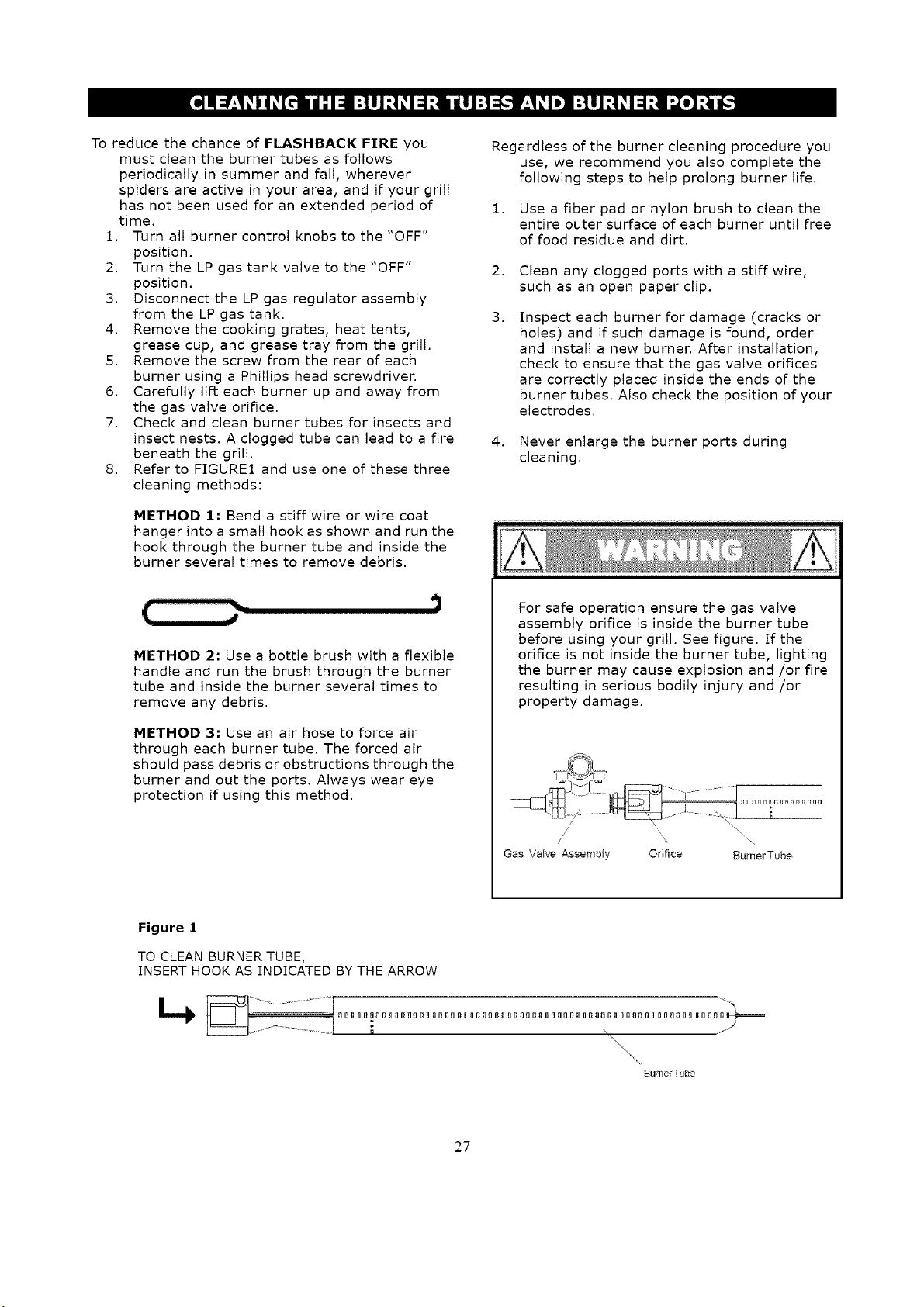
8. Refer to FIGURE1 and use one of these three
cleaning methods:
METHOD 1: Bend a stiff wire or wire coat
hanger into a small hook as shown and run the
hook through the burner tube and inside the
burner several times to remove debris.
Regardless of the burner cleaning procedure you
use, we recommend you also complete the
following steps to help prolong burner life.
1. Use a fiber pad or nylon brush to clean the
entire outer surface of each burner until free
of food residue and dirt.
2. Clean any clogged ports with a stiff wire,
such as an open paper clip.
3.
Inspect each burner for damage (cracks or
holes) and if such damage is found, order
and install a new burner. After installation,
check to ensure that the gas valve orifices
are correctly placed inside the ends of the
burner tubes. Also check the position of your
electrodes.
4. Never enlarge the burner ports during
cleaning.
METHOD 2: Use a bottle brush with a flexible
handle and run the brush through the burner
tube and inside the burner several times to
remove any debris.
METHOD 3: Use an air hose to force air
through each burner tube. The forced air
should pass debris or obstructions through the
burner and out the ports. Always wear eye
protection if using this method.
For safe operation ensure the gas valve
assembly orifice is inside the burner tube
before using your grill. See figure, tf the
orifice is not inside the burner tube, lighting
the burner may cause explosion and/or fire
resulting in serious bodily injury and/or
property damage.
/
Gas Valve Assembly Orifice BumerTube
Figure 1
TO CLEAN BURNER TUBE,
INSERT HOOK AS INDICATED BY THE ARROW
_nl_T b_
2?
Burn-Off
[] Some of the new parts of your grill could have
residual oils. We recommend you ignite the
burners, turn to "HI", and lower the lid for 3 to 5
minutes to burn any oils off before grilling for the
first time.
CAUTION: Operating your grill on the "HI"
setting for longer than five minutes may damage
certain parts of your grill.
Preheating
[] To preheat, light your grill on "HI/LIGHT', lower
the lid, and follow this timetable: for high
temperature cooking, preheat grill 3 to 5
minutes; for low temperature cooking, preheat
grill 3 minutes. Preheating is not necessary to
slow cook.
Cooking Temperature
[] High Setting: The "HI" control knob setting
should only be used to sear some meats,
pre-heat your grill the first 3-Sminutes and for
burning food residue off the grill for 3-5 minutes
after cooking is complete. Never use the "HI"
setting for extended cooking.
Medium to Low Settings: Host recipes specify
medium to low settings, including all smoking
and rotisserie cooking, lean cuts of meat,
chicken, and fish.
An Important Note About Cooking Temperature
[] The outside grilling area is not the controlled
environment that your indoor kitchen is. Many
variables can impact the cooking performance of
your grill, including outside air temperature,
wind, humidity, and altitude. Allow more
cooking time for cold, wind, and higher altitudes.
We recommend you place the grill in an area
protected from wind. Monitor your grill closely
and rotate foods as needed to prevent
overcooking and ensure the most delicious
results every time. Experimenting makes grilling
more fun and interesting!
The middle and back primary cooking areas offer
the highest heat for searing and grilling.
The warming rack offers medium heat for
preparing breads and firm vegetables like
potatoes and corn and keeping food warm.
The front primary cooking area offers less heat
and is ideal for preparing delicate foods and also
for keeping cooked foods warm.
Direct Cooking
[] The direct cooking method is used when food is
placed directly over the lit grill burners. This
method is ideal for searing, grilling, deep frying
and whenever you want foods to have an
open-flame barbecued taste. The lid can be open
or closed depending on your preference.
Indirect Cooking
[] The indirect cooking method is used for most
foods. Do not place the food directly over a
burner to use this method. Instead, the
food should be placed on the left or right side
of your grill with the burner lit on the
opposite side or in the center with the center
burners off. Indirect cooking must be done
with the lid down.
Prepare Cooking Grates for Grilling
[] Greasing the cooking surface will help keep
foods from sticking and reduce the amount of
cleanup required. Use a brush to apply a thin
layer of cooking oil or vegetable shortening
onto each cooking grate. We do not suggest
spray type oils unless they are specified for
high-temperature cooking. Be sure to coat
the entire cooking surface including edges
and any areas with chipped porcelain.
Flare-Ups
[] The fats and juices dripping from grilled food
can cause flare-ups. Flare-ups work to color
and flavor your foods, so some flare-ups are
preferred. Too many can work against you
though. Reduce flare-ups by trimming away
excess fat, using the indirect method of
grilling, and grilling using lower
temperatures.
Failure to comply with these instructions
could result in a fire or explosion that could
cause serious bodily injury, death or property
damage.
Never line the bottom of the firebox with
aluminum foil, sand or any substance that
will restrict the flow of grease into the grease
tray or cup.
Before each use, pull out the grease tray
and remove all grease and food debris to
prevent a grease fire hazard.
Use your grill at least 2 feet away from
any wall or surface. Use your grill at least
2 feet away from combustible objects that
can melt or catch fire (such as vinyl or wood
siding, fences and overhangs) or sources of
ignition including pilot lights on water
heaters and live electrical appliances.
Never use your gas grill in a garage, porch,
shed, breezeway or any other enclosed area.
Your grill will get very hot. Always wear a
flame retardant BBQ Mitt when cooking on
your grill. Never lean over cooking areas
while using grill. Do not touch cooking
surfaces, lid, grill housing or other parts
while grill is in operation, or until the grill has
cooled down after use.
28
Question:
Can I convert my gas grill from one fuel
type to another, such as LP to NG (natural
gas) or vice versa?
Answer:
No, your gas grill is manufactured to specific
standards developed by CSA and ANSI for your
safety and is certified for LPG (Liquid Propane
Gas) use only.
Question:
Are the serial and model numbers of my
grill listed somewhere for reference?
Answer:
The serial and model numbers are listed on a
silver CSA label placed on the grill. Depending
on the grill model, the silver CSA label generally
will be located on the back panel of the cart.
Question:
My grill will not light properly, Why?
Answer:
Check these possibilities:
1. The gas supply is turned off at the LP tank.
Turn on the gas at the LP tank.
2. Your LP tank is out of propane.
3. The regulator is not properly seated in the
tank valve. Remove and reattach. Hand
tighten only.
4. Crimped fuel supply hose. Inspect and
straighten.
5. Regulator failure or damaged hose
assembly. Inspect and order a replacement
part. Do not use your grill if you find a
damaged hose assembly.
6. Gas not getting to the burners. Inspect the
burners under the control panel to be sure
they are aligned with the valve orifices.
7. Blockage in the gas system. Inspect
burners and valve orifices for blockages,
such as spider webs, insects, etc. Clean as
necessary.
Questions:
My electronic ignition is not working.
Answer:
Listen to hear the electronic igniter clicking. If
not, check these possibilities:
1. Replace the AA battery. Ensure the "+"
end is facing up and out.
2. Ensure the battery is centered and fits into
the electronic igniter button properly.
3. Be sure the wires are all attached to the
electronic ignition assembly behind the
control panel and the individual electrodes.
4. Inspect the electrodes to be sure they are
not coated with grease or dirt. If so, clean
with rubbing alcohol.
29
If you hear a clicking sound, then:
1.Inspect the electrodes to be sure they
are not coated with grease and dirt.
Clean with rubbing alcohol.
2. Inspect the distance from the electrode
to the burner. It should be 1/8 to 1/4
inch from the main burner and 1/8 to
3/16 inch from the side burner.
Question:
Sometimes I hear a humming sound
coming from my regulator. What
causes this?
Answer:
The humming sound is gas flowing
through the regulator. This is more likely
to occur in periods of high gas flow. A low
volume of sound is normal and will not
interfere with the operation of your grill.
Question:
My grill has a low flame on some
burners, or some burners will not
light at all, What can cause this?
Answer
This can be caused by the flow limiting
device, which is generally triggered by a
sudden change in pressure. Opening
the tank valve too fast or shutting the
burners off using the tank valve can
cause this. To reset:
1. Close the LP tank valve and
disconnect the regulator
assembly from the tank.
2. Let the LP tank sit for 10
minutes.
3. Open all burner control knobs,
including the side burner, to "HI"
at the same time.
4. Close all burner control knobs.
5. Reconnect the gas regulator to
the LP tank.
6. Follow the burner lighting
procedures and light the burner
farthest from the LP tank.
Question:
Where do I use my grill for safer
operation and better performance?
Answer:
Strong winds and low temperatures can
affect the heating and performance of
your gas grill so factor in these elements
when positioning your grill outdoors for
cooking.
Use your grill at least 2 feet away from
any wall or surface.
Useyourgrillat least2feetawayfrom
combustibleobjectsthatcanmeltorcatchfire
(suchasvinylor wood siding, fence and
overhangs) or sources of ignition including pilot
lights on water heaters and live electrical
appliances.
Never use your gas grill in a garage, porch,
shed, breezeway or any other enclosed area.
Never obstruct the flow of ventilation air
around your gas grill housing.
with a paper towel over the
entire surface, corners, and edges. Preheat
your grill to 500 degrees. Turn half your
burners to "LOW" and half "OFF", and place
grates in the firebox for about an hour.
Shut off all burners and allow the grates to
cool. We recommend you coat the grates
with a liquid vegetable oil before each use.
We do not suggest spray type oils unless
they are specified for high temperature
cooking.
Question:
The Regulator and Hose supplied with my
gas grill does not fit the older LP Gas Tank
I've used for years. Why not?
Answer:
The U.S. Government regulates gas appliances
and LP gas tanks. When regulations are
changed the LP gas tank fittings are altered to
insure compliance. If your LP gas tank does not
fit the regulator and hose assembly supplied
with your new grill, then the tank is outdated
and must be replaced. Note: Effective April 1,
2002 all LP gas tanks sold must include an
"OPD" Overfill Prevention Device. The OPD
tanks are identified by their triangular-shaped
valve wheel. This internal device prevents the
LP gas tank from being overfilled. Tanks without
an OPD valve can no longer be refilled.
Question:
Is it safe to clean my porcelain coated
cooking grates in the dishwasher?
Answer:
We recommend you clean all parts of your grill,
including the cooking grates, by hand.
Question:
Can I clean parts of my grill, such as the
cooking grates and heat tents, in a
self-cleaning oven?
Answer:
No. You should not clean any part of your grill
in a self-cleaning oven.
Question:
What can I do to keep my cast iron grates
from rusting?
Answer:
Cast iron grates do require special care. We
recommend you first season new grates. Wash
new grates with dishwashing liquid, rinse, and
dry completely with a soft cloth. Never wash
them in a dishwasher. We recommend you use a
solid vegetable shortening over the grates to
season them the first time. Spread a thin coating
30
Repair Protection Agreements
Congratulations on making a smart purchase.
Your new Kenmore (_ product is designed and
manufactured for years of dependable
operation. But like all products, it may require
repair from time to time. That's when having a
Repair Protection Agreement can save you
money and aggravation.
Purchase a Repair Protection Agreement
now and protect yourself from unexpected
hassle and expense.
Here's what's included in the Agreement:
[] Expert service by our 12,000 professional
repair specialists
[] Unlimited service and no charge for
parts and labor on all covered repairs
[] Product replacement if your covered
product can't be fixed
[] Discount of 10% from regular price of
service and service-related parts not
covered by the agreement; also, 10% off
regular price of preventive maintenance
check
[] Fast help by phone - phone support from
Sears technician on products requiring
in=home repair, plus convenient repair
scheduling
Once you purchase the Agreement, a simple
phone call is all that it takes for you to schedule
service. You can call anytime day or night, or
schedule a service appointment online.
Sears has over 12,000 professional repair
specialists, who have access to over 4.5 million
quality parts and accessories. That's the kind of
professionalism you can count on to help
prolong the life of your new purchase for years
to come. Purchase your Repair Protection
Agreement today!
Some limitations and exclusions apply,
For prices and additional information call
1-800-827-6655.
For Sears professional installation of home
appliances, garage door openers, water heaters,
and other major home items, in the U.S.A. call
1-800-4-MY-HOME®
Your Home
iiiiiiiiiiiiiiii iiiiiiiiiiiiiiiii
For I =parer-mnyour home-d all m_dor brand apphances
lawn and garden equipment or heath'lg and cooling systems,
no matter who made it, no rnai'ter w'ho soid it:!
For the replacement _parts.accessories and
owners rnari, uals that you need to do-it-yourself
Fo_r"Sears profes_onal installation of home appliances
and terns ke carac e door oeners and water heaters
,,,,,,,,,,,,,,,, , g ,J P............... ,,,,,,,,,,,,,,,,
-800-4-MY-HOME (1-80e-469-4663)
Call anytime, day or night U.S.A." and Carlada)
www,seal's.com www, sears,ca
OurHome
For repair of c ' ................
.arry-m items like vacuums, lawn e '.....
................. .,quipmer_t,
and electronics, call or go ondine for the tocation of you, nearest
see,.Po... o oi,so.i oCo°,or
'"'"'"'"'"' 1-8:00-48:8-12:2:2: '"'"'"'"'"'
_:_,R_isl_red Trademark ,__ Trad=_',=_k "_u._&ervieeMark of Sears Brands, LLC
#_Mar_ Regisir_Ja f t_ Mates de F_I:,H_ _: Msr,_a _ S_',_ieio ,_ S_.Ts Brands, LLC
_z:_Marque de ,temn_ee,* _ Marquedep_eede Sears B_:ards, LLC
@$_s Brands,LLC
3!