Loading ...
Loading ...
Loading ...
19
The previous directions are the preferable way to mount the new rear grill. The units performance is
slightly better and the possibility of draughts is reduced. As a last resort, direct mounting of the grille
to the unit can be considered.
Note: The grille must be installed prior to inserting the unit into the sleeve.
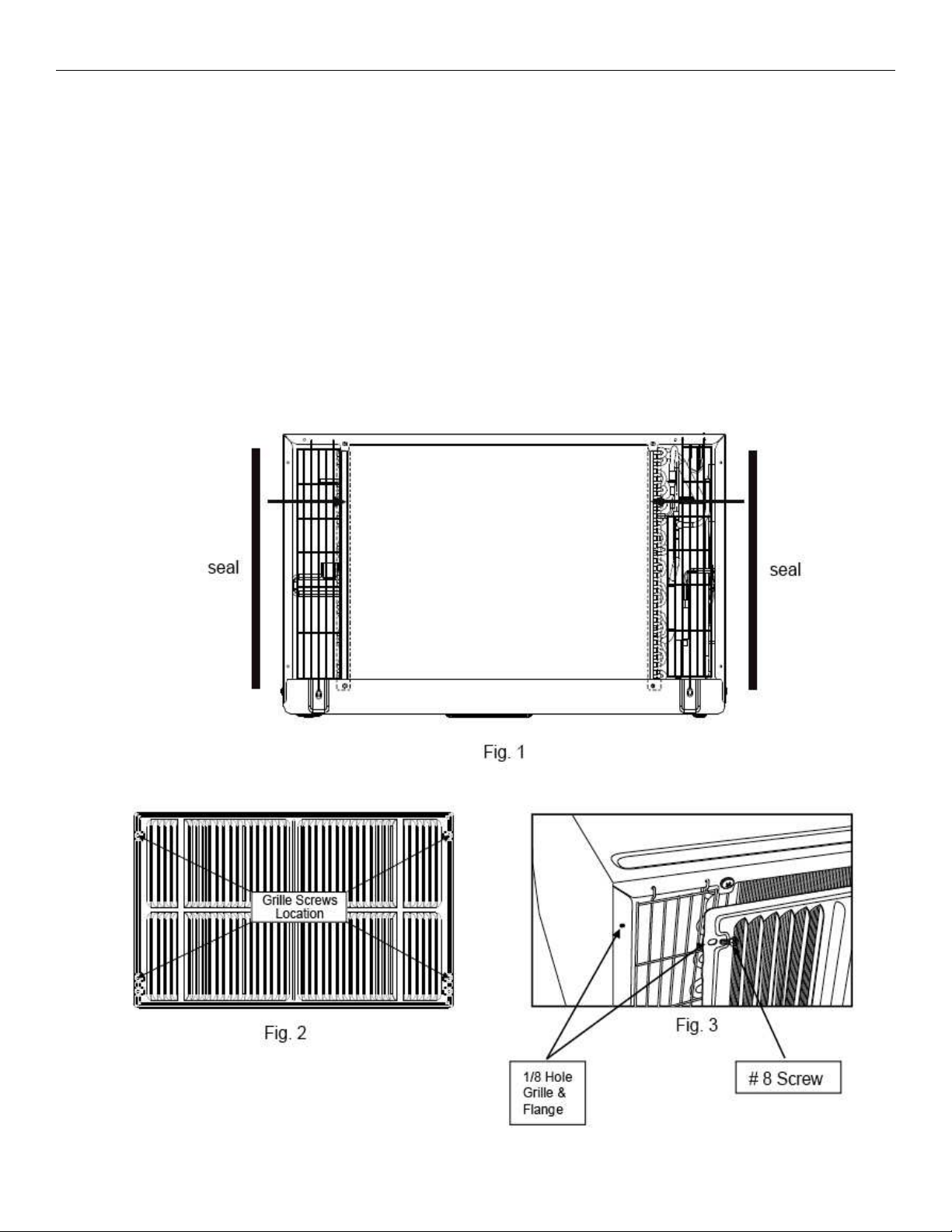
1. Attach the 2 seal pieces (1 X3/8 X14 ) as shown in Fig. 1.
2.Position the grille over the rear of the unit making sure that:
a. The double set of screw holes are at the bottom.
b. The fins of the grill are pointed away from the unit.
3. Align the top of the grille with the top of the unit. The overhang on each side is equal.
4. If the unit has not been pre-drilled (some models), carefully drill 4-1/8 holes through the
grille and into the side flange of the unit approximately 1 to 2 from the top and bottom as
in Fig. 2, 3 .
(Be careful not to drill into the copper heat exchanger coils.)
5. Install 4 - #8 self tapping screws to affix the grille to the unit.
6. Insert the unit into the sleeve.
1
/
2
INSTRUCCIONES DE MONTAJE DIRECTO:
Las instrucciones anteriores reeren al modo preferente de montar la nueva rejilla posterior. El desempeño de la unidad es
ligeramente mejor y la posibilidad de las corrientes de aire se reduce. Como un último recurso, se puede considerar el monta-
je directo de la parrilla en la unidad.
Nota: La rejilla debe instalarse antes de colocar la unidad en la carcasa.
1. Coloque 2 piezas de junta (1” x 3/8” x 14”) como se muestra en la Fig. 1.
2. Coloque la rejilla en la parte posterior de la unidad asegurándose que:
a. El doble juego de oricios para tornillos está en la parte inferior
b. Las pestañas de la rejilla apuntan hacia afuera de la unidad.
3. Alinee la parte superior de la parrilla con la parte superior de la unidad. La en ambos lados es igual.
4. Si la unidad no ha sido pre-perforada (algunos modelos), con cuidado perfore 4 oricios de 1/8” en la parrilla y en el
lado de la pestaña de la unidad aproximadamente de 1 ½” a 2” de la parte superior y de la parte inferior como se muestra en
las Fig. 2 y 3.
(Tenga cuidado de no perforar los serpentines de intercambio de calor de cobre)
5. Instale 4 tornillos autoperforantes del #8 para jar la parrilla a la unidad.
6. Inserte la unidad en la carcasa.
Loading ...
Loading ...
Loading ...