Loading ...
Loading ...
Loading ...
Hanging Mount
Tools required for assembly:
No. 2 Phillips screwdriver (not supplied)
10 mm wrench (not supplied)
NOTE: Hang the unit at least 7 Feet above floor level and
away from corners and any heating or cooling vents.
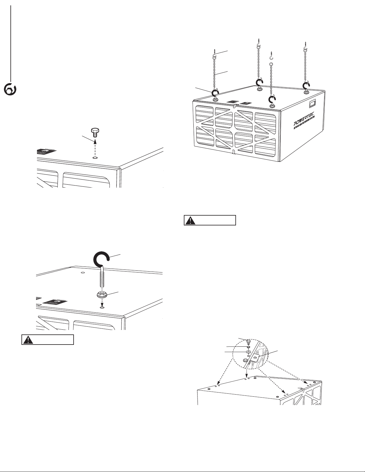
• Remove four screws from the cabinet top (Figure 5).
NOTE: Save the four screws for future use. These
screws will be needed to seal the holes in the cabinet
top if the eye bolts are removed.
Figure 5
Screw
• Thread a flange bolt almost all the way up onto each
eye bolt. (Figure 6)
• Thread the eye bolt into the hole on the cabinet top.
Tighten the eye bolt and flange nut against the top of
the cabinet.
• Repeat for remaining three eye bolts.
Figure 6
Eye Bolt
Flange Nut
CAUTION
Mounting hooks must be anchored to a building
structure which can support a minimum of 100
pounds. Never mount to surface such as dry wall or
false ceiling grids, etc.
• Anchor the four chain, cable or steel strapping lines (not
supplied) into the buildings ceiling joist. Never mount to
surface such as dry wall or false ceiling grids, etc.
• Attach a chain (not supplied) to each hanging eye bolt.
NOTE: When the chains hang down freely they should
be 15-1/4" from left to right and 24-1/2" from front
to rear.
• With assistance raise and secure the air filtration system
eye bolts to the four hanging lines (Figure 7).
Anchor
(not supplied)
Chain, Cable or
Steel Strapping
Lines
(not supplied)
Eye Bolt
Figure 7
• Ensure the unit is level horizontally. Adjust if needed.
• Plug the power cord into the correct receptacle. (Refer
to Power Source paragraph in this section of the
manual.)
Flush Mounting
CAUTION
Mounting hardware must be anchored to a building
structure which can support a minimum of 100
pounds. Never mount to surface such as dry wall or
false ceiling grids, etc.
• Mark the air filtration system bolt pattern on the mounting
surface. NOTE: Bolt pattern should be 17-1/4" from left
to right and 31" from front to rear.
• Drill holes in the mounting surface at the marks.
• Mounting bracket holes are found on each side of the
unit, slide the mounting brackets under the cover lip and
secure the mounting brackets to the unit with the 3 in 1
M6 Bolts (with flat washer and lock washer). Tighten all
bolts. (Figure 8)
Figure 8
Mounting
Brackets
Hex Bolt
Flat Washer
Lock Washer
• With assistance, carefully lift the air filtration system in
place aligning drilled holes to mounting brackets. Bolt the
air filtration system in place.
NOTE: Use 1/4" shank lag bolts for studs or 1⁄4" nuts,
bolts, and washers for mounting to supports.
4
ASSEMBLY
Loading ...
Loading ...
Loading ...