IMPORTANT MANUAL Do Not Throw Away
S _A/RS
Operator's
Manual
@
Model No.
358.351141
358.351061
CUSTOMER
ASSISTANCE
1-800-235-5878
Mon,- Sat.7 a.m.- 7 p.m.
Sun. 10 a.m. - 7 p.m.
_b ARNING:
READ THE OPERATOR'S
MANUAL AND FOLLOW
ALL WARNINGS AND
SAFETY INSTRUCTIONS.
FAILURE TO DO SO CAN
RESULT IN SERIOUS
INJURY.
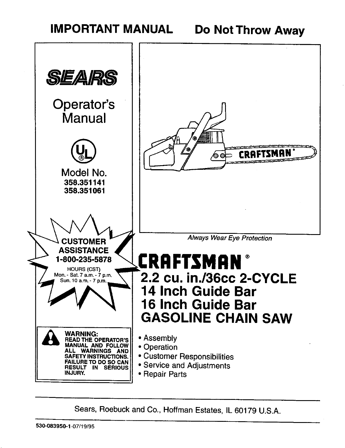
CRAFTSMAN"
Always Wear Eye Protection
FTSMRN°
2.2 cu. in./36cc 2-CYCLE
14 Inch Guide Bar
16 Inch Guide Bar
GASOLINE CHAIN SAW
• Assembly
• Operation
• Customer Responsibilities
• Service and Adjustments
• Repair Parts
Sears, Roebuck and Co., Hoffman Estates, IL 60179 U.S.A.
530-083950-1-07/19/95
SAFETY RULES
WARNING:
ALWAYS DISCONNECT SPARK PLUG WIRE AND PLACE WIRE WHERE IT CANNOT CONTACT SPARK
PLUG TO PREVENT ACCIDENTAL STARTING WHEN SETTING UP,TRANSPORTING, ADJUSTING OR
MAKING REPAIRS EXCEPT CARBURETOR ADJUSTMENTS.
BECAUSE A CHAIN SAW IS A HIGH-SPEED WOOD-CUTTING TOOL, SPECIAL SAFETY
PRECAUTIONS MUST BE OBSERVED TO REDUCE THE RISK OF ACCIDENTS. CARELESS OR
IMPROPER USE OF THIS TOOL CAN CAUSE SERIOUS INJURY.
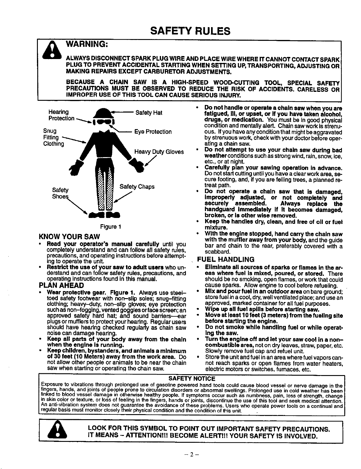
Hearing
Protection
Snug
Fitting
Clothing
Safety Hat
Eye Protection
Heavy Duty Gloves
Safety Safety Chaps
Shoe_
Figure 1
KNOW YOUR SAW
• Read your operator's manual carefully until you
completely understand and can follow all safety rules,
precautions,and operating instructionsbeforeattempt-
ingto operate the unit.
Restrict the use of your sew to adult users who un-
derstand and can followsafety rules, precautions,and
operating instructionsfound in this manual.
PLAN AHEAD
• Wear protective gear. Figure 1. Always use steel-
toed safety footwear with non-slip soles; snug-fitting
clothing; heavy-duty, non-slip gloves; eye protection
suchas non-fogging, vented gogglesorfaca screen;an
approved safety hard hat; and sound barders---ear
plugsor mufflerstoprotectyourhearing. Regular users
shouldhave hearing checked regularly as chain saw
noisecan damage hearing.
• Keep all parts of your body away from the chain
when the engine Is running.
Keep children, bystanders, end animals a minimum
of 30 feet (10 Meters) away from the work area. Do
not allow other people or animals to be near the chain
saw when startinq or operatin.qthe chain saw.
• Do not handle or operate a chain saw when you are
fatigued, III, or upset, or If you have taken alcohol,
drugs, or medication. You must be in good physical
conditionand mentallyalert. Chain saw workisstrenu-
ous. ifyou haveany conditionthatmightbeaggravated
bystrenuouswork, checkwith yourdoctorbeforeoper-
ating a chainsaw.
• Do not attempt to use your chain saw during bad
weather conditionssuchas strongwind, rain,snow,ice,
etc., or at night.
• Carefully plan your sawing operation in advance.
Do notstartcuttinguntilyou have a clearworkarea, se-
cure footing,and, if you are felling trees, a planned re-
treat path.
• Do not operate a chain saw that is damaged,
improperly adjusted, or not completely and
securely assembled. Always replace the
handguard Immediately If It becomes damaged,
broken, or Is other wise removed.
• Keep the handles dry, clean, and free of oil or fuel
mixture.
• With the engine stopped, hand carry the chain saw
with the muffler away from your body, and the guide
bar and chain to the rear, preferably covered with a
scabbard.
FUEL HANDLING
Eliminate all sources of sparks or flames In the ar-
eas where fuel Is mixed, poured, or stored. There
should be no smoking,openflames, orwork thatcould
cause sparks. Allow engine to coolbefore refueling.
• Mix and pour fuel In an outdoor area onbare ground; •
store fuel ina cool,dry,wellventilated place;and usean
approved, marked containerfor all fuel purposes.
• Wipe up all fuel spills before starting saw.
Move at least 10 feet (3 meters) from the fueling site
before starting the engine,
• Do not smoke while handling fuel or while operat-
Ing the saw.
• Turn the engine off and let your saw cool in a non-
combustible area, noton dryleaves, strew,paper,etc.
Slowly remove fuel cap and refuel unit.
• Store the unitandfuel inan area where fuelvaporscan-
not reach sparks or open flames from water heaters,
electric motorsor switches,furnaces, etc.
SAFETY NOTICE ]
Exposuretovibrationsthroughprolongeduseofgasolinepoweredhandtoolscouldcausebloodvesselornervedamageinthe|
fingers, hands, and joints of people pronetocirculationdisordersor abnorma swe lings. Prolongedusein coldweatherhas been I
linkedto bloodvesseldamage inotherwisehealthy people. If symptoms occursuchas numbness, pan, ossofstrength, change |
inskincolorortexture or lossoffeelinginthefingershandsorjoints,discontnuetheuseofths too andseekmedica attenton I
An anti-vibrationsystemdoesnotguaranteetheavoidanceoftheseprobems.Userswhooperatepowertoolsona continualand|
regularbasismustmonitorcloselytheirphysca conditionandtheconditionofthisunit. . J
LOOK FOR THIS SYMBOL TO POINT OUT IMPORTANT SAFETY PRECAUTIONS.
IT MEANS - ATTENTIONII! BECOME ALERTIH YOUR SAFETY IS INVOLVED.
-- '7--
SAFETY RULES
OPERATE YOUR SAW SAFELY
• Do not operate a chain saw with one hand. Serious
injuryto the operator, helpers,bystandersor any combina-
tion ofthese persons may resultfrom one-handed opera-
tion.A chainsaw isintended fortwo-handed use.
• Operate the chain saw only in well-ventilated outdoor
areas.
• Do not operate saw from a ladder or in a tree, unless
specificallytrained to do so.
• Position all parts of your body to the left of cut and
away from the chain when the engine Is running.
• Cut wood only. Do not useyoursaw to pry or shove away
limbs, roots,or other objects.
• Make sure the chain will not make contact with any
object while starting the engine. Never try to startthe
saw when the guide bar is in a cut or kerr.
• Use extreme caution when cutting small size brush
and saplings. Slender materialcan catch the chain and
be whippedtoward you or pullyou offbalance.
• Be alert for springback when cuttinga limbthat isunder
tension so you willnot be struckbythe limbor saw when
the tension inthe wood fibers is released.
• Do not put pressure on the saw at the end of a cut.
Applyingpressure can cause you to lose controlwhen the
cut iscompleted.
• Stop the engine before setting the saw down.
• Keep fuel and oil caps, screws, and fasteners securely
tightened.
MAINTAIN YOUR SAW IN GOOD WORKING
ORDER
• Have all chain saw service performed by your Sears
Service Center withtheexceptionofthe itemslistedinthe
"Customer Responsibilities"section of this manual. For
example, if impropertoolsare used to remove or holdthe
flywheel when servicingthe clutch, structuraldamage to
the flywheel can occurand cause the flywheel to burst.
• Make cartaln the chain stops moving when the throttle
trigger is released. For correction, refer to "Carburetor
Adjustments."
• Stop the saw if the chain strikes a foreign object.
Inspectunitand repairor replaceparts as necessary.
• Disconnect the spark plug before performing any
malntenanca exceptfor carburetor adjustments
• Never modify your saw in any way. Use only attach-
monts suppliedor specificallyrecommended bythe manu-
facturer.
• Use only Sears accessories and replacement parts
as recommended.
TRANSPORTING AND STORAGE
• Stopthe unitbeforetransporting.
• Allow engine to cool, cover the guide bar and chain, and
securethe unitbeforestoringor transportingin a vehicle.
• Emptyfuel tank before storingor transportingthe unit.Use
up any fuel leftinthe carburetor bystartingthe engine and
lettingthe engine rununtilitsteps.
• Store unit and fuel in an area where fuel vapors cannot
reach sparks or open flames from water heaters, electric
motors or switches,furnaces, etc.
• Store unitsothe chain cannotaccidentally cause injury.
• Store the unitoutof the reach of children.
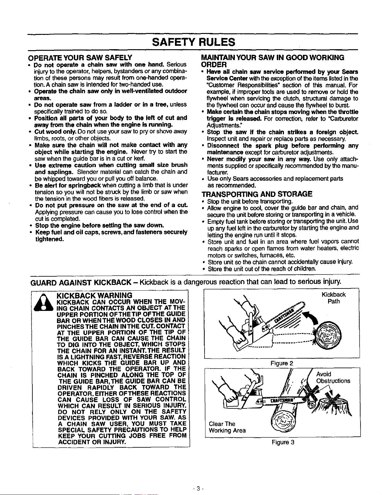
GUARD AGAINST KICKBACK - Kickback is a dangerous reaction that can lead to serious injury.
KICKBACK WARNING
KICKBACK CAN OCCUR WHEN THE MOV-
ING CHAIN CONTACTS AN OBJECT ATTHE
UPPER PORTION OFTHETIP OFTHE GUIDE
BAR OR WHEN THE WOOD CLOSES IN AND
PINCHES THE CHAIN IN THE CUT. CONTACT
AT THE UPPER PORTION OF THE TIP OF
THE GUIDE BAR CAN CAUSE THE CHAIN
TO DIG INTO THE OBJECT, WHICH STOPS
THE CHAIN FOR AN INSTANT.THE RESULT
IS A LIGHTNING FAST, REVERSE REACTION
WHICH KICKS THE GUIDE BAR UP AND
BACK TOWARD THE OPERATOR. IF THE
CHAIN IS PINCHED ALONG THE TOP OF
THE GUIDE BAR,THE GUIDE BAR CAN BE
DRIVEN RAPIDLY BACK TOWARD THE
OPERATOR. EITHER OFTHESE REACTIONS
CAN CAUSE LOSS OF SAW CONTROL
WHICH CAN RESULT IN SERIOUS INJURY.
DO NOT RELY ONLY ON THE SAFETY
DEVICES PROVIDED WITH YOUR SAW. AS
A CHAIN SAW USER, YOU MUST TAKE
SPECIAL SAFETY PRECAUTIONS TO HELP
KEEP YOUR CUTTING JOBS FREE FROM
ACCIDENT OR INJURY.
Kickback
Path
Figure 2
Obstructions
Clear The
Working Area
Figure 3
3
SAFETY RULES
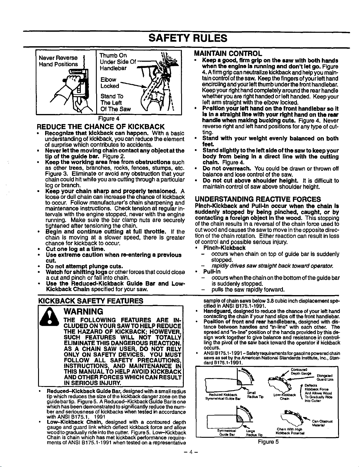
Never Reverse
Hand Positions
Thumb On _,\]
Under Side Of _,_ "_
Handlebar _
Elbow _;'/m
Locked
Stand To //_
TheLe. t'
Of The Saw _ f
Figure 4
REDUCE THE CHANCE OF KICKBACK
• Recognize that kickback can happen. With a basic
understandingof kickback, you can reduce the element
of surpdse which contributesto accidents.
• Never let the moving chain eentact any object at the
tip of the guide bar. Figure2.
Keep the working area free from obstructions such
as other trees, branohes, rooks, fences, stumps, etc.
Figure 3. Eliminate or avoid any obstructionthat your
chaincould hit while you are cuttingthrougha particular
logor branch.
• Keep your chain sharp and properly tensioned. A
looseor dull chain can increasethe chance of kickback
to occur. Follow manufacturer's chain sharpening and
maintenance instructions. Check tension at regular in-
tervals with the engine stopped, never with the engine
running. Make sure the bar clamp nuts are securely
tightenedafter tensioning the chain.
• Begin and continue cutting at full throttle. If the
chain is moving at a slower speed, there is greater
chance for kickback tooccur.
• Cut one log at a time.
• Use extreme caution when re-entering a previous
cut.
Do not attempt plunge cuts,
• Watch for shifting logs or otherforcesthat could close
a cutand pinch or fall intochain.
Use the Reduced-Kickback Guide Bar and Low-
Kickback Chain specified for your saw.
MAINTAIN CONTROL
• Keep a good, firm grip on the saw with both hands
when the engine Is running end don't let go, Figure
4. Afirmgdpcanneutralizekickback and helpyou main-
taincontrolofthesaw. Keepthefingers ofyourlefthand
encirclingand yourleftthumbunderthe fronthandlebar.
Keep yourdght handcompletely aroundthe rear handle
whetheryou are dghthandedor left handed. Keep your
leftarm straightwiththe elbow locked.
• Pc,sltlon your left hand on the front handlebar so It
is in a straight line with your right hand on the rear
handle when making bucking cuts. Figure4. Never
reverse dght and lefthandpositionsfor anytype ofcut-
ting.
• Stand with your weight evenly balanced on both
feel
• Stand slightly to the left side of the saw to keep your
body from being In a direct line with the cutting
chain. Figure 4.
• Do not overreach. You could be drawn or thrown off
balance and losecontrolofthe saw.
• Do not cut above shoulder height. It is difficultto
maintain controlof saw above shoulder height.
UNDERSTANDING REACTIVE FORCES
Pinch-Kickback end Pull-In occur when the chain Is
suddenly stopped by being pinched, caught, or by
contacting a foreign oh|act In the wood. This stopping
ofthe chain resultsin a reversalof the chain force used to
cutwoodand causesthesawtomove intheOppositedirec-
tionofthe chainrotation. Eitherreaction can resultin loss
ofcontroland possibleserious injury.
• Pinch-Kickback
- occurswhen chain on top of guide bar is suddenly
stopped.
- rapidlydrivessaw straightback towardoperator.
• Pull-In
- occurswhenthechainonthebottomofthe guidebar
issuddenlystopped.
- pullsthe saw rapidlyforward.
KICKBACK SAFETY FEATURES
& WARNING
THE FOLLOWING FEATURES ARE IN-
CLUDED ON YOUR SAW TO HELP REDUCE
THE HAZARD OF KICKBACK; HOWEVER,
SUCH FEATURES WILL NOT TOTALLY
ELIMINATE THIS DANGEROUS REACTION.
AS A CHAIN SAW USER, DO NOT RELY
ONLY ON SAFETY DEVICES. YOU MUST
FOLLOW ALL SAFETY PRECAUTIONS
INSTRUCTIONS, AND MAINTENANCE IN
THIS MANUAL TO HELP AVOID KICKBACK
AND OTHER FORCES WHICH CAN RESULT
IN SERIOUS INJURY.
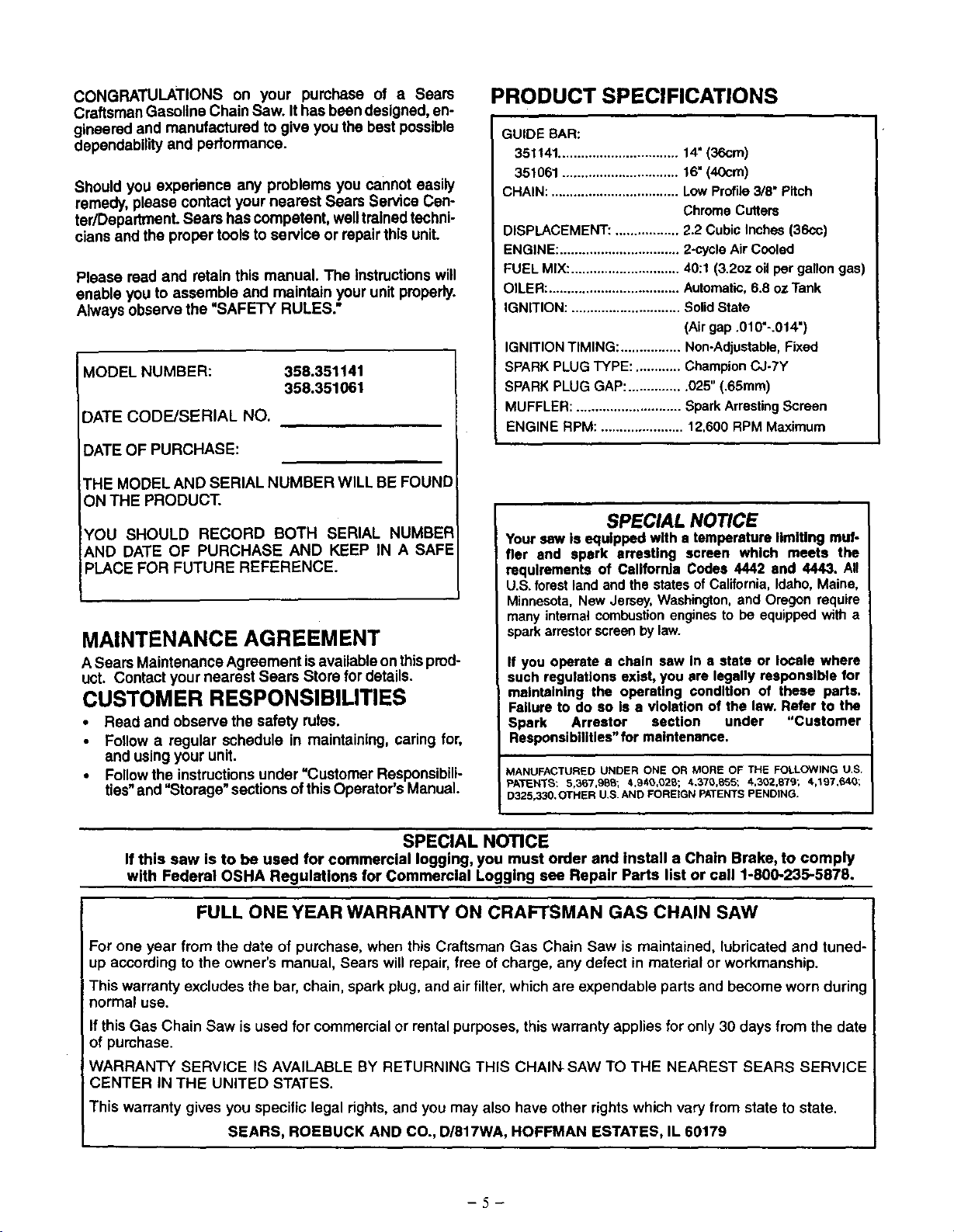
Reduced-Kickback Guide Bar, designed witha small radius
tipwhich reduces the size ofthe kickbackdanger zone on the
guidebartip. Figure5. A Reduced-KickbackGuide Barisone
whichhas been demonstrated to significantlyreduce the num-
ber and seriousness of kickbackswhen tested in accordance
withANSI B175.t. 1991
Low--Klokbeck Chain, designed with a contoured depth
gauge and guard linkwhich deflect kickback force and allow
woodtograduallyrideintothecutter. Figure5. Low-Kickback
Chain ischain which has met kickback pedormance require-
ments of ANSI B175.1-1991 when testedon a representative
sample of chain sawsbelow3.8 cubic inch displacement spe-
cified in ANSI B175.1-1991.
Hendguard, designed to reduce the chance of your lefthand
contacting_e chain ifyour hand slips off the front handlebar.
Position of front sndresr handlebars, designed with dis-
tance between handles and "in-line"with each other. The
spread and =in-line" positionofthe hands provided bythis de-
_iing(nt_,/O_vtoO_toe_jertog_l_abc_,anwC_r_ndresislal_Crei_r_control_
• g p" to eope to " kickba
occurs.
ANSIel 75.1-1991- Safetyrequirementsforgasolinepoweredchain
sawsassetbytheAmedcanNationaJStandardsInstitute,Inc.,Stan-
dardB175.1-1991.
Reduced )Ockback Smell
Symmet,ical Guide Bar Radius T_O
Contour¢d
j/ Ded_Gauge Ek_ga_d
__ Guardk_
_min _. _ _edually Ride
_nto Cutter
Symmet,_cll Large
auk_ Bar RadkJSTip
Chain With High
_ Potlm_d
Figure5
-4-
CONGRATULATIONSon your pumhaseof a Sears
CraftsmanGasoline Chain Saw. Ithas been designed, en-
gineered and manufactured to give you the best possible
dependability and performance.
Should you experience any problems you cannot easily
remedy, please contact your nearest Sears Service Cen-
ter/Department. Sears has competent, welltrained techni-
cians and the proper tools to service or repairthis unit.
Please read and retain this manual. The Instructions will
enable you to assemble and maintain your unit properly,
Always observe the "SAFETY RULES."
MODEL NUMBER:
358.351141
358.351061
DATE CODEJSERIAL NO.
DATE OF PURCHASE:
THE MODEL AND SERIAL NUMBER WILL BE FOUND
ON THE PRODUCT.
IYOU SHOULD RECORD BOTH SERIAL NUMBEF_
AND DATE OF PURCHASE AND KEEP IN A SAFE
PLACE FOR FUTURE REFERENCE.
MAINTENANCE AGREEMENT
ASears Maintenance Agreement isavailableon thisprod-
uct. Contact your nearest Sears Store for details.
CUSTOMER RESPONSIBILITIES
• Read and observe the safety rules.
Follow a regular schedule in maintaining, caring for,
and usingyour unit.
• Followthe instructionsunder"Customer Responsibili-
ties"and "Storage" sectionsofthisOperator's Manual.
PRODUCT SPECIFICATIONS
GUIDE BAR:
351141................................14"(36cm)
351061...............................16"(40cm)
CHAIN:..................................LowProfile3/8" Pitch
ChromeCutters
DISPLACEMENT:.................2.2 CubicInches(36cc)
ENGINE:................................2-cycleAirCooled
FUELMIX:.............................40:1(3.2ozoilper gallongas)
OILER:...................................Automatic,6.8 ozTank
IGNITION:.............................SolidState
(Airgap.010"-.014")
IGNITIONTIMING:................ Non-Adjustable,Fixed
SPARKPLUGTYPE:............ ChampionCJ-7Y
SPARKPLUGGAP:...............025"(.65mm)
MUFFLER:............................SparkArrestingScreen
ENGINERPM: ......................12,600RPM Maximum
SPECIAL NOTICE
Yoursaw is equipped with s temperaturelimiting muf-
fler and spark arresting screen which meets the
requirements of California Codes 4442 and 4443. All
U.S.forestlandandthestatesofCalifornia,Idaho,Maine,
Minnesota,NewJersey,Washington,and Oregonrequire
manyinternalcombustionenginesto be equippedwith a
sparkarrestorscreenbylaw.
If you operate a chain saw in s state or locale where
such regulations exist, you are legally responslMe for
maintaining the operating condition of these parts.
Failure to do so is a violation of the law. Refer to the
Spark Arrestor section under "Customer
Responsibilities" for maintenance.
MANUFACTURED UNDER ONE OR MORE OF THE FOLLOWING U.S.
PATENTS: 5,367,98S; 4.94e,o2_,; 4,370,B55; 4,302,879; 4,197,640;
D325,330.OTHER U.S.AND FOREIGN PATENTS PENDING,
SPECIAL NOTICE
If this saw is to be used for commercial logging, you must order end install a Chain Brake, to comply
with Federal OSHA Regulations for Commercial Logging see Repair Parts list or call 1-800-235-5878.
FULL ONE YEAR WARRANTY ON CRAFTSMAN GAS CHAIN SAW
For one year from the date of purchase, when this Craftsman Gas Chain Saw is maintained, lubricated and tuned-
up according to the owner's manual, Sears will repair, free of charge, any defect in material or workmanship.
This warranty excludes the bar, chain, spark plug, and air filter, which are expendable parts and become worn during
normal use.
If this Gas Chain Saw is used for commercial or rental purposes, this warranty applies for only 30 days from the date
of purchase.
WARRANTY SERVICE IS AVAILABLE BY RETURNING THIS CHAIN SAW TO THE NEAREST SEARS SERVICE
CENTER IN THE UNITED STATES.
This warranty gives you specific legal rights, and you may also have other rights which vary from state to state.
SEARS, ROEBUCK AND CO., DI617WA, HOFFMAN ESTATES, IL 60179
-5-
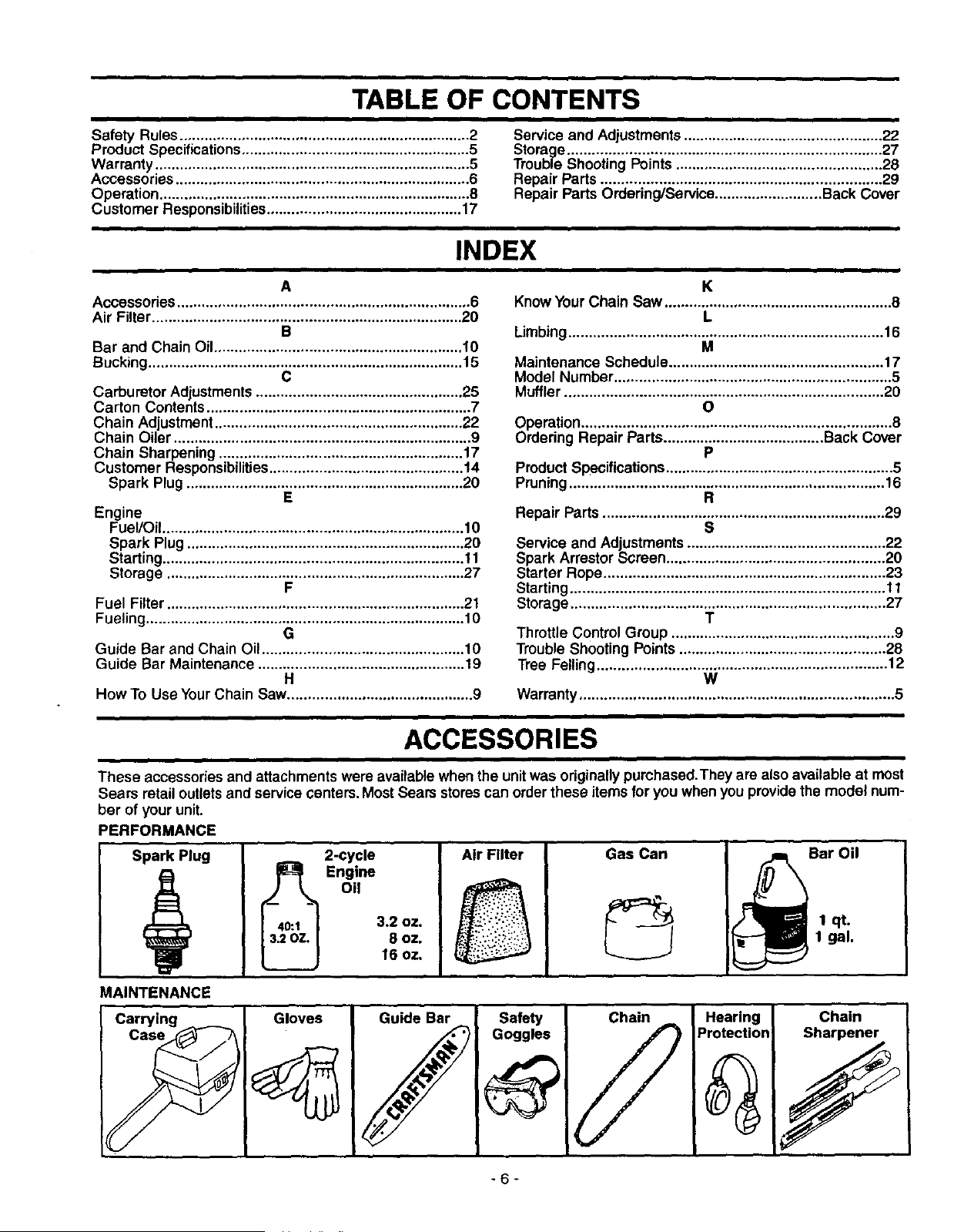
TABLE OF CONTENTS
Safety Rules...................................................................... 2 Service and Adjustments ................................................ 22
Product Specifications ....................................................... 5 Storage ............................................................................ 27
Warranty ............................................................................ 5 Trouble Shooting Points .................................................. 28
Accessories ....................................................................... 6 Repair Parts.................................................................... 29
Operation ........................................................................... 8 Repair Parts Ordering/Service .......................... Back Cover
Customer Responsibilities ............................................... 17
INDEX
A
Accessories ....................................................................... 6
Air Filter ........................................................................... 20
B
Bar and Chain Oil ............................................................ 10
Bucking ............................................................................ 15
C
Carburetor Adjustments .................................................. 25
Carton Contents ................................................................ 7
Chain Adjustment ............................................................ 22
Chain Oiler ........................................................................ 9
Chain Sharpening ........................................................... 17
Customer Responsibilities ............................................... 14
Spark Plug ................................................................... 20
E
Engine
Fuel/Oil ......................................................................... 10
Spark Plug ................................................................... 20
Starting ......................................................................... 11
Storage ........................................................................ 27
F
Fuel Filter ........................................................................ 21
Fueling ............................................................................. 10
G
Guide Bar and Chain Oil ................................................. 10
Guide Bar Maintenance .................................................. 19
H
How To Use Your Chain Saw............................................. 9
K
Know Your Chain Sew ....................................................... 8
L
Limbing............................................................................ 16
M
Maintenance Schedule .................................................... 17
Model Number ................................................................... 5
Muffler ............................................................................. 20
O
Operation ........................................................................... 8
Ordering Repair Parts ....................................... Back Cover
P
Product Specifications....................................................... 5
Pruning ............................................................................ 16
R
Repair Parts .................................................................... 29
S
Service and Adjustments ................................................ 22
Spark Arrestor Screen ..................................................... 20
Starter Rope .................................................................... 23
Starting ............................................................................ 11
Storage ............................................................................ 27
T
Throttle Control Group ...................................................... 9
Trouble Shooting Points .................................................. 28
Tree Felling ...................................................................... 12
W
Warranty ............................................................................ 5
ACCESSORIES
These accessories and attachments were availablewhen the unitwas originally purchased.They are also available at most
Sears retail outletsand service (:enters.Most Sears storescan orderthese items for you when you providethe model num-
ber of your unit.
PERFORMANCE
Spark Plug Bar Oil2-cycle
_ Engine
Oil
3.2 oz.
8 oz.
16 oz,
Air Filter Gas Can
1 qt.
1 gal.
MAINTENANCE
• Safety _ Chain _ ]prHoetmcitnogn"[
-6-
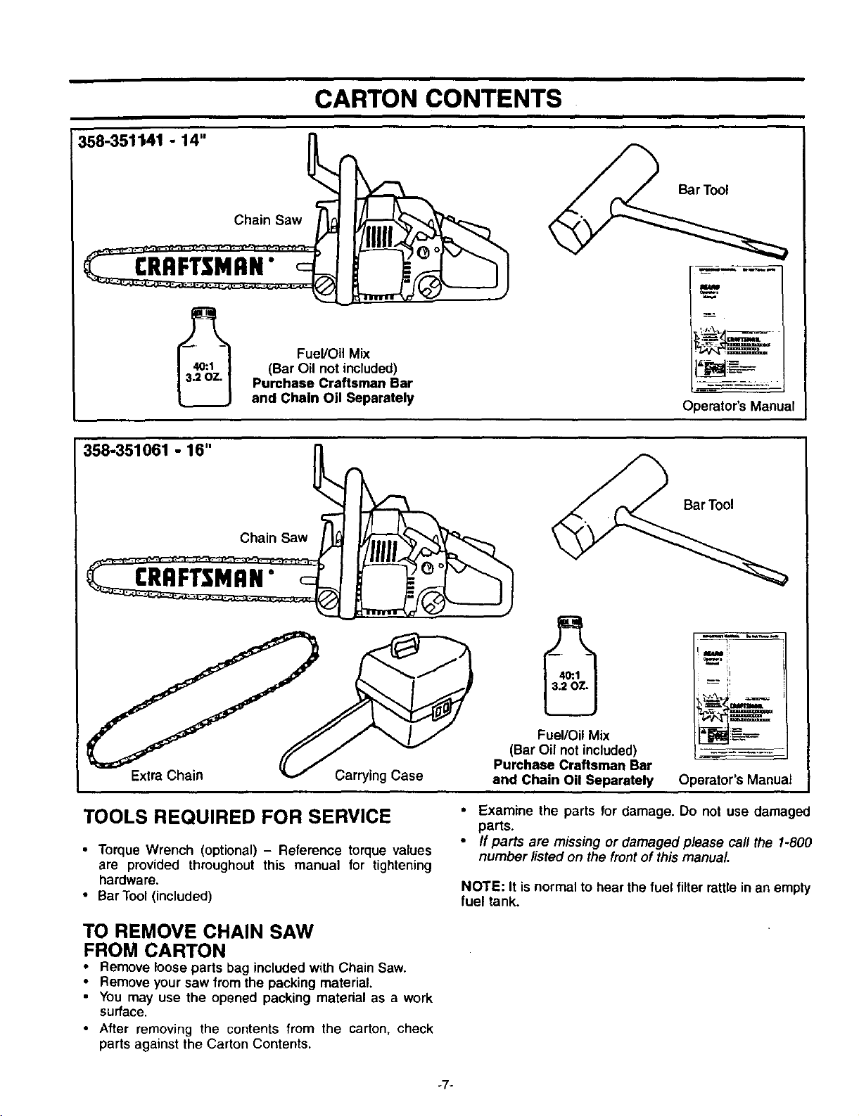
CARTON CONTENTS
358-351141 - 14"
Fuel/Oil Mix
(Bar Oil not included)
Purchase Craftsman Bar
and Chain Oil Separately
_r_ol
Operator's Manual
358-351061 - 16" {_
Chain Saw
Extra Chain
Carrying Case
Fuel/Oil Mix
(Bar Oil not included)
Purchase Craftsman Bar
and Chain Oil Separately
Bar Tool
i oP==.i_
Operator's Manual
TOOLS REQUIRED FOR SERVICE
• Torque Wrench (optional) - Reference torque values
are provided throughout this manual for tightening
hardware.
• Bar Tool (included)
• Examine the parts for damage. Do not use damaged
parts.
• If parts are missing or damaged please call the 1-800
number listed on the frontof this manual
NOTE: It is normal to hear the fuel filterrattle in an empty
fuel tank.
TO REMOVE CHAIN SAW
FROM CARTON
• Remove loose parts bag included with Chain Saw.
• Remove your saw from the packing material.
• You may use the opened packing matedal as a work
surface.
• After removing the contents from the carton, check
parts against the Carton Contents.
ii 111 • m ill ,
OPERATION
i ,J
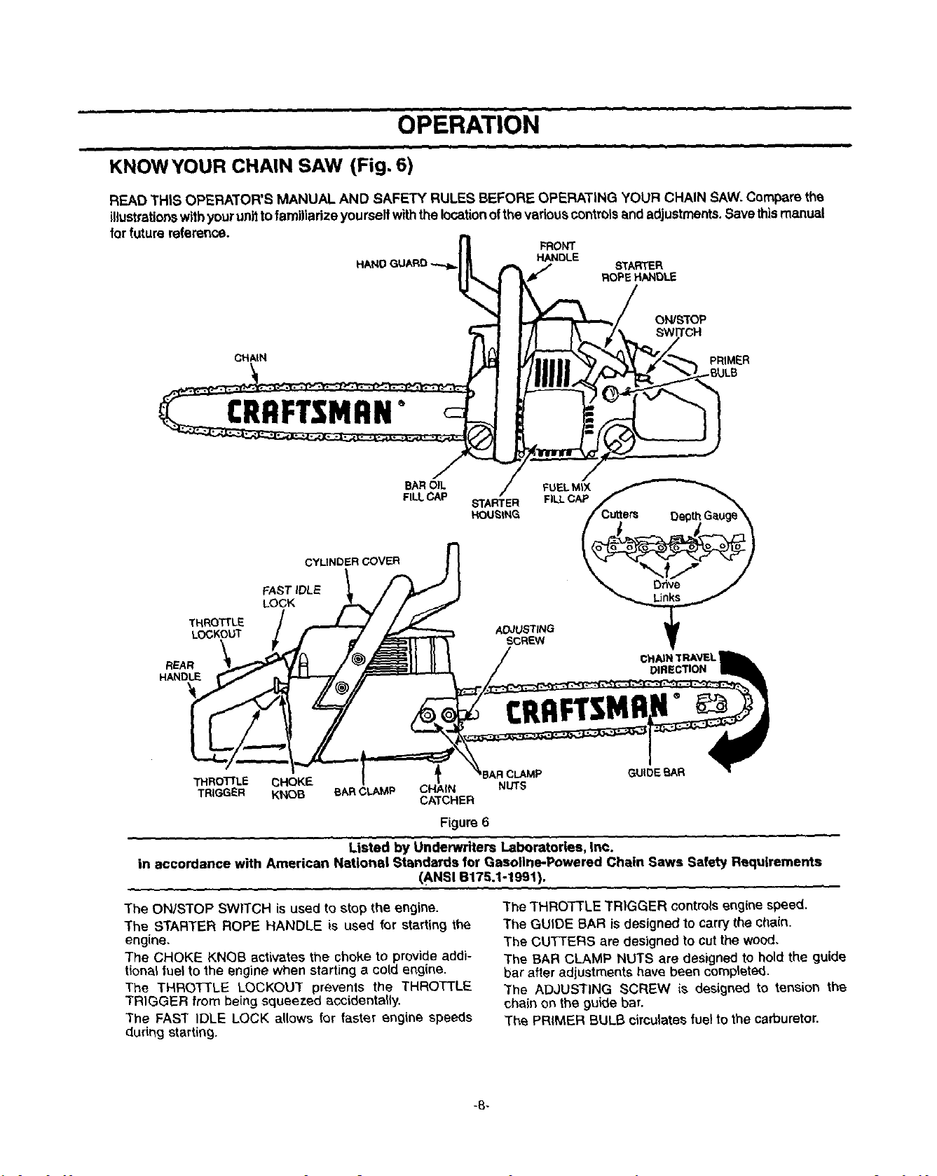
KNOWYOUR CHAIN SAW (Fig, 6)
READ THIS OPERATOR'S MANUAL AND SAFETY RULES BEFORE OPERATING YOUR CHAIN SAW. Compare the
illustrationswithyour uni_tofamiliarize yourseltwiththe locationofthe variouscontrolsand adjustments. Save thismanual
for future reference.
FRONT
HAt,K) GUARD _ _ H_NDLE STARTER
ROPE HANDLE
ON/STOP
CH/_N PRIMER
CRRFTgMRN°
CYLINDER COVER
FAST IDLE
LOCK
THROTTLE
LOCKOUT
REAR
HANDLE
BAR OIL
FILL CAP
FUEL MIX
STARTER FILL CAP /
HOUSING
ADJUSTING _1_
SCREW 11r
CHAIN TRAVEL
DIRECTION
CRfl
THROTTLE CHOKE _ I CLAMP
TRIGGER KNOB BAR CLAMP CHAIN NUTS
CATCHER
Figure6
Listed by Underwriters Laboratories, Inc.
in accordance with American National Standards for Gasotine-Powered Chain Saw,= Safety Requirements
(ANSI B175.1-1991).
The ONiSTOP SWITCH is used to stop the engine.
The STARTER ROPE HANDLE is used for starting the
engine.
The CHOKE KNOB activates the choke to provide addi-
tional fuel to the engine when starting a cold engine.
The THRO]_LE LOCKOUT prevents the THROTTLE
TRIGGER from being squeezed accidentally.
The FAST IDLE LOCK allows for faster engine speeds
during starting.
The THROTTLE TRIGGER controls engine speed.
The GUIDE BAR is designed to carry the chain.
The CU'I_'ERS are designed to cut the wood.
The BAR CLAMP NUTS are designed to hold the guide
bar after adjustments have been completed.
The ADJUSTING SCREW is designed to tension the
chain on the guide bar,
The PRIMER BULB circulates fuel to the carburetor.
-8-
OPERATION
HOWTO USE YOUR CHAIN SAW
STOPPING YOUR ENGINE
• Move on/stop switch to the "stop" position.
• If engine does not stop, pull bluechoke knobout fully.
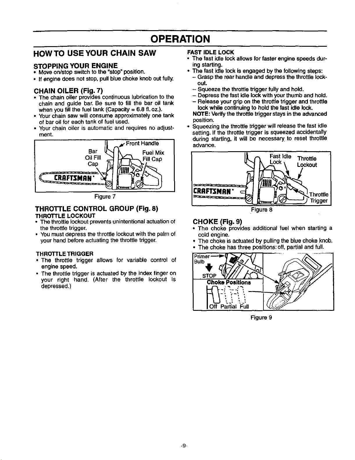
CHAIN OILER (Fig. 7)
• The chain oiler provides continuous lubricationto the
chain and guide bar. Be sure to fill the bar oil tank
when you fillthe fuel tank (Capacity = 6.8 fLoz.).
• Your chain saw will consume approximately one tank
of bar oil for each tank of fuel used.
• Your chain oiler is automatic and requires no adjust-
roent,
Bar
Oil Fill
Cap
CRRFTSMRN"
Fuel Mix
II Cap
Figure 7
THRO'I-rLE CONTROL GROUP (Fig. 8)
THROTTLE LOCKOUT
• The throttle lockoutprevents unintentionalactuation of
the throttletrigger.
• You must depress the throttle lockoutwith the palm of
your hand before actuating the throttle trigger.
THROTTLE TRIGGER
• The throttle trigger allows for variable control of
engine speed.
• The throttle trigger is actuated by the index finger on
your right hand. (After the throttle lockout is
depressed.)
FAST IDLE LOCK
• The fast idle lock allows for faster engine speeds dur-
ing starting.
• The fast idle lock isengaged bythe followingsteps:
- Grasp the rear handle and depress the throttle lock-
out.
- Squeeze the throttletrigger fully and hold.
- Depress the fast idlelock with yourthumb and hold.
- Release your gripon the throttletrigger and throttle
lock while continuingto hold the fast idle lock.
NOTE: Verify the throttle trigger staysin the advanced
position.
• Squeezing the throttle trigger will release the fast idle
setting. If the throttle trigger is squeezed accidentally
during starting, it will be necessary,to reset throttle
advance.
CRRFT_MRN"
Trigger
Figure 8
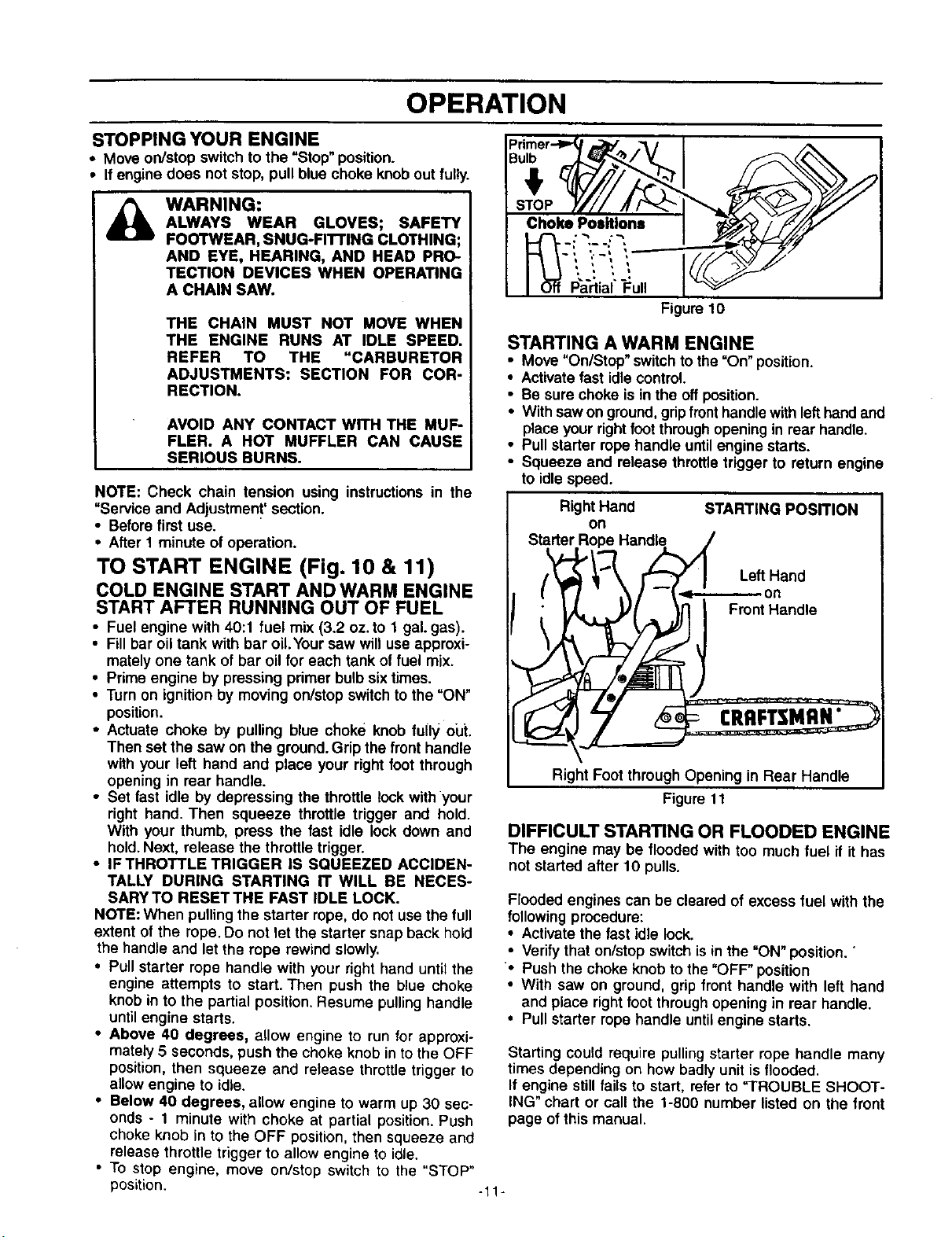
CHOKE (Fig. 9)
• The choke provides additional fuel when starting a
cold engine,
• The choke is actuated by pullingthe bluechoke knob.
• The choke has three positions:off,partial and full.
Choke Positions
O_ff -_p!_iaiiii!,,
Figure 9
-9-
OPERATION
BEFORE STARTING ENGINE:
WARNING:
BE SURE TO READ THE FUEL HANDLING
INFORMATION IN THE SAFETY RULES
SECTION ON PAGE 2 OF THIS MANUAL
BEFORE YOU BEGIN.
IF YOU DO NOT UNDERSTAND THE FUEL
HANDLING SECTION DO NOT ATTEMPT
TO FUEL YOUR UNIT; SEEK HELP FROM
SOMEONE THAT DOES UNDERSTAND
THE FUEL HANDLING SECTION OR CALL
THE CUSTOMER ASSISTANCE HOTMNE
AT 1-800-235-5878,
GUIDE BAR AND CHAIN OIL
For maximum guide bar and chain lifo, we recommend
you use Craftsman chain saw bar oil if Craftsman bar oil
isnot available, you may use a good grade SAE30 oiluntil
you are able to obtain Craftsman brand.The oil output is
automatically metered during operation.Your saw willuse
approximatelyone tank ofbar oilfor every tank offuel mix.
Always fill the bar oil tank when you fill the fuel tank.
GASOLINE
The two-cycle engine on this product requires a fuel mix-
ture of regular unleaded gasoline and a high quality 40:1
2-cycle engine oil (AIR-COOLED) for lubrication of the
bearings and other moving parts. The correct fuel/oil mix-
ture is 40:1 (see Fuel Mixture Chart).Too little oil or the
incorrect oil type will cause poor performance and may
cause the engine to overheat and seize.
Gasoline and oil must be premixed in a clean approved
fuel container. Always use fresh regular unleaded gaso-
line.
FUEL STABILIZER
Fuel stabilizer is an acceptable alternative in minimizing
the formation of fuel gum deposits during storage. Add
stabilizer to gasoline in fuel tank or storage container.
Always follow the fuel mix ratio found on the stabilizer
container. Runengine at least 5 minutes after adding sta-
bilizer to allow the stabilizer to reach the carburetor.You
do not have to drain the fuel tank for storage if you are
using fuel stabilizer.
CRAFTSMAN 40:1 2-cycle engine oil (AIR-COOLED) is
specifically blendedwith fuel stabilizers.Ifyou do not use
this Sears oil, you can add a fuel stabilizerto your fuel
tank.
40:1 2-CYCLE AIR-COOLED ENGINE OIL
CRAFTSMAN 40:1 2-cycle engine oil (AIR-COOLED) is
specifically blended with fuel stabilizers. If you do not
use this Sears oil, you can add a fuel stabilizer to your
fuel mix. See "Gasoline and oil mixture" instructions
below.
If CRAFTSMAN 40:1 2-cycle engine oil (AIR-COOLED) is
not available, use a good quality 2-cycle engine oil (AIR-
COOLED) that has a recommended fuel mix ratio of 40:1.
IMPORTANT! Do not use:
• AUTOMOTIVE OIL
• BOAT OILS (NMMA, BIA, etc.)
These oils do not have proper additives for 2-cycle (AIR-
COOLED) engines and can cause engine damage.
GASOLINE AND OIL MIXTURE
MIX GASOLINE AND OIL AS FOLLOWS:
• Consult chart for correctquantities.
• Do not mix gasoline and oil directly in the unit's fuel
tank.
This engine is certified to operate on unleaded gasoline.
IMPORTANT: Experience indicates that alcohol blended
fuels called gasohol (or using ethanol or methanol) can
attract moisture, which leads to oil/gas separation and
formation of acids during storage. Acidic gas can damage
the fuel system of an engine while in storage. To avoid
engine problems, the fuel system should be emptied
before storage for 30 days or longer. Drain the gas tank,
then run the fuel out of the carburetor and fuel lines by
starting the engine and letting it run until it stops. Use
fresh fuel next season. See STORAGE instructions for
additional information. Never use engine or carburetor
cleaner products in the fuel tank or permanent damage
may occur.
FOR ONE GALLON:
• Pour 3.2 ounces of high quality,40:1 2-cycle engine oil
(AIR-COOLED) into an empty, approved one gallon
gasoline container.
• Add one gallon of regular unleaded gasoline to the
gallon container, then securely replace the cap. Shake
the container momentarily.
• The mixture is now ready for use. Fuel stabilizer can be
added at this time if desired;follow mixing instructions
on the label.
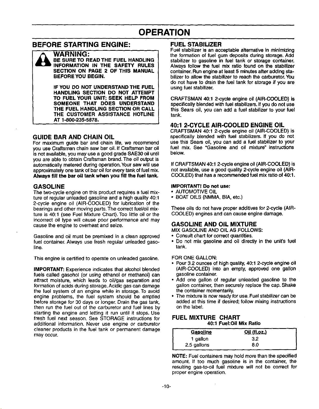
FUEL MIXTURE CHART
40:1 FuehOil Mix Ratio
1 gallon 3.2
2.5 gallons 8.0
NOTE: Fuel containers may hold more than the specified
amount. If too much gasoline is in the container, the
resulting gas-to-oil fuel mixture will not be correct for
proper engine operation.
-10-
OPERATION
STOPPING YOUR ENGINE
• Move on/stop switch to the "Stop" position.
• If engine does not stop, pull blue choke knob out fully.
_ ARNING:
ALWAYS WEAR GLOVES; SAFETY
FOOTWEAR, SNUG-FITTING CLOTHING;
AND EYE, HEARING, AND HEAD PRO-
TECTION DEVICES WHEN OPERATING
A CHAIN SAW.
THE CHAIN MUST NOT MOVE WHEN
THE ENGINE RUNS AT IDLE SPEED•
REFER TO THE "CARBURETOR
ADJUSTMENTS: SECTION FOR COR-
RECTION.
AVOID ANY CONTACT WITH THE MU_
FLER. A HOT MUFFLER CAN CAUSE
SERIOUSBURNS•
NOTE: Check chain tension using instructionsin the
"Service and Adjustment' section.
• Beforefirst use.
• After 1 minute of operation•
TO START ENGINE (Fig. 10 & 11)
COLD ENGINE START AND WARM ENGINE
START AFTER RUNNING OUT OF FUEL
• Fuel engine with 40:1 fuel mix (3.2 oz.to 1 gal.gas).
• Fillbar oil tank with bar oil.Your saw will use approxi-
matelyone tank of bar oil for each tank of fuel mix.
• Prime engine by pressing primer bulb sixtimes.
• Turn on ignition by moving on/stop switchto the "ON"
position.
• Actuate choke by pulling blue choke knob fu(I,/ou[
Then set the saw on the ground.Grip the front handle
with your left hand and place your right foot through
opening in rear handle.
• Set fast idle by depressing the throttle lock with your
right hand. Then squeeze throttle trigger and hold.
With your thumb, press the fast idle lock down and
hold.Next, release the throttle trigger.
• IF THROTTLE TRIGGER IS SQUEEZED ACCIDEN-
TALLY DURING STARTING IT WILL BE NECES-
SARYTO RESETTHE FAST IDLE LOCK.
NOTE: When pullingthe starter rope, do not usethe full
extent of the rope. Do not let the starter snap back hold
the handle and let the rope rewind slowly.
• Pull starter rope handle with your right hand until the
engine attempts to start. Then push the blue choke
knob in to the partial position.Resume pullinghandle
until engine starts.
• Above 40 degrees, allow engine to run for approxi-
mately 5 seconds, push the choke knob in to the OFF
position, then squeeze and release throttle trigger to
allow engine to idle.
• Below 40 degrees, allow engine to warm up 30 sec-
onds - 1 minute with choke at partial position.Push
choke knob in to the OFF position,then squeeze and
release throttle trigger to allow engine to idle.
• To stop engine, move on/stop switch to the "STOP"
_.l • _0
Partial Full
Figure 10
STARTING A WARM ENGINE
• Move "On/Stop"switch to the =On"position.
• Activate fast idlecontrol.
• Be sure choke is in the offposition.
• With saw on ground,gripfront handlewith lefthandand
place your rightfoot throughopening in rear handle.
• Pull starter rope handle untilengine starts.
• Squeeze and release throttletrigger to return engine
to idlespeed.
RightHand STARTING POSITION
on
Starter R Handle.!/
• "o. ond
t Front Handle
Right Foot through Opening in Rear Handle
Figure 11
DIFFICULT STARTING OR FLOODED ENGINE
The engine may be flooded with too much fuel it it has
not started after 10 pulls.
Flooded engines can be cleared of excess fuel with the
following procedure:
• Activate the fast idle lock.
• Verify that on/stop switch is in the "ON" position. "
• Push the choke knob to the "OFF" position
• With saw on ground, grip front handle with left hand
and place right foot through opening in rear handle.
• Pull starter rope handle until engine starts.
Starting could require pulling starter rope handle many
times depending on how badly unit is flooded.
If engine stillfails to start, refer to =TROUBLE SHOOT-
ING" chart or call the 1-800 number listed on the front
page of this manual.
position.
-11-
OPERATION
GENERAL OPERATION TIPS
• Cut wood only.Do not cut metal; plastics;masonry;non-
wood buildingmaterials; etc.
• Stop the saw ifthe chain strikes a foreignobject.Inspect
the saw and repair or replace parts as necessary.
• Keep the chain out of dirt and sand. Even a small
amount of dirtwill quicklydull a chain and thus increase
the possibilityof kickback.
To get the "feel" of using your saw before you begin a
major sawing operation, practice cutting a few small logs
using the followingtechnique:
• Accelerate engine to full throttle by squeezing the throt-
tle triggerbefore entering cut.
• Never cutwith engine at partial speeds.
• Begin cutting withthe saw chassis against the log.
• Keep engine at fullthrottle duringcutting procedure.
• Allow the chain tocut for you;exert only lightdownward
pressure. If you force the cut, damage to the bar, chain,
or engine can result.
• Release the throttle trigger as soon as the cut is com-
pleted, allowing the engine to idle. If you run the unit at
full throttle without cutting,unnecessary wear can occur
tothe chain, bar, and engine.
• To avoid losingcontrol when completingthe cut, do not
put pressure on the saw dudngthe end ofthe cut.
• Stop engine beforesetting unitdown after operation.
OPERATION SAFETY
WARNING
IF SAW BECOMES PINCHED OR HUNG IN
A LOG, DO NOT TRY TO FORCE IT OUT.
YOU CAN LOSE CONTROL OF THE SAW
RESULTING IN INJURY AND/OR DAMAGE
TO THE SAW. STOP THE SAW, DRIVE A
WEDGE OF PLASTIC OR WOOD INTOTHE
CUT UNTIL THE SAW CAN BE REMOVED
EASILY. RESTART THE SAW AND CARE-
FULLY REENTER THE CUT. TO AVOID
KICKBACK AND CHAIN DAMAGE, DO NOT
USE A METAL WEDGE. DO NOT A'I'rEMPT
TO RESTART YOUR SAW WHEN IT IS
PINCHED OR HUNG IN A LOG.
KICKBACK CAN OCCUR WHEN THE MOV-
ING CHAIN CONTACTS AN OBJECT AT
THE UPPER PORTION OF THE TIP OF THE
GUIDE BAR OR WHEN THE WOOD CLOS-
ES IN AND PINCHES THE SAW CHAIN IN
THE CUT. CONTACT ATTHE UPPER POR-
TION OFTHETIP OFTHE GUIDE BAR CAN
CAUSE THE CHAIN TO DIG INTO THE
OBJECT AND STOP THE CHAIN FOR AN
INSTANT, THE RESULT IS A LIGHTNING
FAST,REVERSE REACTION WHICH KICKS
THE GUIDE BAR UP AND BACK TOWARD
THE OPERATOR. IF THE SAW CHAIN IS
PINCHED ALONG THE TOP OF THE GUIDE
BAR, THE GUIDE BAR CAN BE DRIVEN
RAPIDLY BACK TOWARD THE OPERATOR.
EITHER OF THESE REACTIONS CAN
CAUSE LOSS OF SAW CONTROL WHICH
CAN RESULT IN SERIOUS INJURY.
AVOID REACTIVE PINCH FORCES
Pinch-Kickback and Pull-In occur when the chain is sud-
denly stopped by being"pinched,caught, or by contacting
a foreign object in the wood.This sudden stopping of the
chain results in a reversal of the chain force used to cut
wood and causes the saw to move in the opposite direc-
tion of the chain rotation. Pinch-Kickback drives the saw
straight back toward the operator. Pull-In pulls the saw
away from the operator. Either reaction can result in loss
of controland possiblyserious injury.
TO AVOID PINCH-KICKBACK:
• Be extremely aware of situations or obstructions that
can cause material to pinchthe top of or otherwise stop
the chain.
• Do not cut more than one logat a time.
• Do not twist the saw as the bar is withdrawn from an
under-cut when bucking.
TO AVOID PULL-IN
• Always begin cutting with the engine at full throttle and
the saw housingagainst wood.
• Use wedges made of plasticor wood, (never of metal)
to hold the cut open.
-12o
OPERATION
TREE FELLING
I _ IF THE TRUNK OR MMBS ARE Rot"rING,
_mi.im THEY CAN FALL UNEXPECTEDLY AND
CAUSE SERIOUS INJURY.
AS YOU MAKE YOUR FELLING CUT, IF THE
/ SAW APPEARSTO BE BINDING,THETREE IS
STARTING TO FALL IN THE WRONG DIREC-
/ TION. IMMEDIATELY STOP THE SAW AND
/ USE A FELLING WEDGE AND MAUL (HAM-
/ MER) TO FORCE THE FELUNG CUT OPEN.
/ THE WEDGE WILL HOLD THE FELLING CUT
/ OPEN ALLOWING YOU TO REMOVE THE
SAW. KEEP EVERYONE AWAY FROM THE
| TREE IN ALL DIRECTIONS.
DETERMINETHE NATURAL FALL DIRECTION
• Wind - A treeevenlybalancedwillfallinthe samedirection
the windisblowing,
• Lean - Use a carpenter'slevelor plumbbob to determine
iftree has a naturallean. A leaning tree willtend tofall in
directionof lean.
• Shape - A tree willfend to fall towardssidethat is more
heavily branched.
• Other Factors - Contacting or nearby trees, buildings, or
wires can influence the direction the tree will fall.
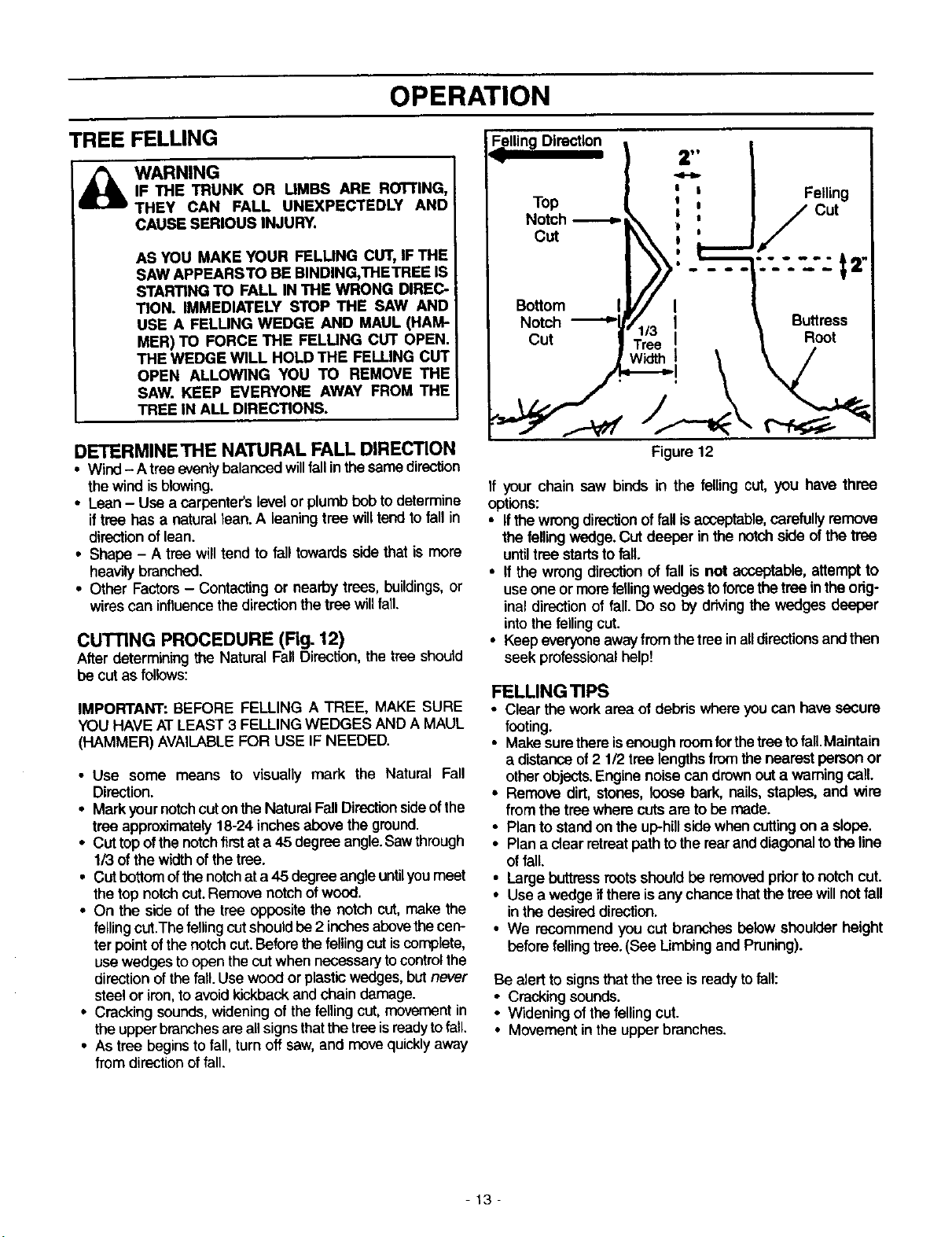
CUTTING PROCEDURE (Fig. 12)
After determining the Natural FallDirection, the tree should
be cut as follows:
IMPORTANT: BEFORE FELLING A TREE, MAKE SURE
YOU HAVE AT LEAST 3 FELLINGWEDGES AND A MAUL
(HAMMER) AVAILABLEFOR USE IF NEEDED.
• Use some means to visually mark the Natural Fall
Direction.
• Mark your notch cut on the Natural Fall Directionsideof the
tree approximately 18-24 inches above the ground.
• Cut top ofthe notch first at a 45 degree angle.Sawthrough
1/3 of the width of the tree.
• Cut bottom ofthe notch at a 45 degree angle untilyou meet
the top notch cut. Remove notch of wood.
• On the side of the tree opposite the notch cut, make the
felling cut.The felling cut should be 2 inches abovethe cen-
ter point of the notch cut.Before the felling cut iscomplete,
use wedges to open the cut when necessary to control the
direction of the fall.Use wood or plastic wedges, but never
steel or iron, to avoid kickback and chain damage.
• Cracking sounds, widening of the felling cut, movement in
the upper branches are all signs that the tree isreadyto fail.
• As tree begins to fall, turn off saw, and move quickly away
from direction of fall
F"n00"O'°n} ,: I
_ I ', ' I Felling
lop i 0 Cut
Notch _ , I /
J./...
I>>'"-" !.... -t="
Bottom II//jV/ I i
Notch ._.._r/1/3 i , Buttress
cut | Tree I L Root
Figure 12
If your chain saw binds in the felling cut, you have three
options:
• Ifthe wrongdirectionoffall isacceptable,carefully remove
the felling v,_lge. CUt deeper in the notchside ofthe tree
untiltree startsto fall.
• If the wrong direction of fall is not acceptable,attempt to
useone or morefelling wedgestoforce thetree intheorig-
inal direc'tionof fall. Do so by drivingthe wedges deeper
intothe felling cut.
• Keep everyoneawayfrom thetreeinalldirectionsand then
seek professionalhelp!
FELLING TIPS
• Clear the work area of debris where you can have secure
footing.
• Make surethereisenough roomforthetreeto fall.Maintain
a distanceof 2 1/2 tree lengthsfromthenearest person or
otherobjects.Engine noisecan drownouta warning call.
• Remove dirt, stones,loose bark, nails,staples, and wire
from the treewhere cutsare to be made.
• Planto standon the uphill sidewhen cuttingon a slope.
• Plan a clear retreatpathto therearand diagonaltothe line
of fall.
• Large buttress roots should be removed prior to notch cut.
• Use a wedge ifthere is any chance that the tree will not fall
in the desired direction.
• We recommend you cut branches below shoulder height
before felling tree. (See Limbing and Pruning).
Be alert to signs that the tree is readytofall:
• Cracking sounds.
• Wideningofthe felling cut.
• Movementin theupper branches.
-13-
OPERATION SAFETY
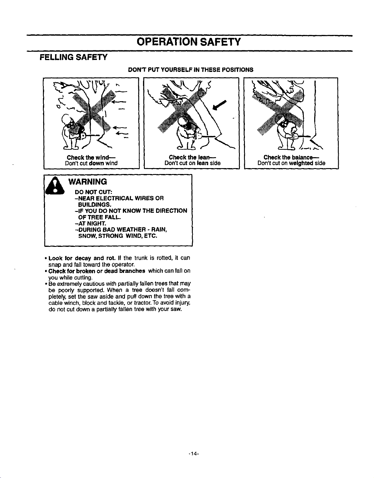
FELLING SAFETY
DON'T PUT YOURSELF IN THESE POSITIONS
f-,
Check the wind--
Don't cut down wind
Check the lean--
Don't cut on lean side
Check the balance--
Don't cuton weighted side
WARNING
DO NOT CUT:
-NEAR ELECTRICAL WIRES OR
BUILDINGS.
-IF YOU DO NOT KNOW THE DIRECTION
OF TREE FALL.
-AT NIGHT.
-DURING BAD WEATHER - RAIN,
SNOW, STRONG WIND, ETC.
• Look for decay and rot. If the trunk is rotted, it can
snap and fall toward the operator.
• Check for broken or dead branches whichcan fall on
you while cutting.
• Be extremely cautiouswith partiallyfallen treesthat may
be poorly supported. When a tree doesn't fall com-
pletely, set the saw aside and pull down the tree with a
cable winch, blockand tackle, or tractor.To avoid injury,
do not cut down a partiallyfallen tree with your saw.
-14-
OPERATION
BUCKING
Buckingis cutting a fallentree to the desired log size.
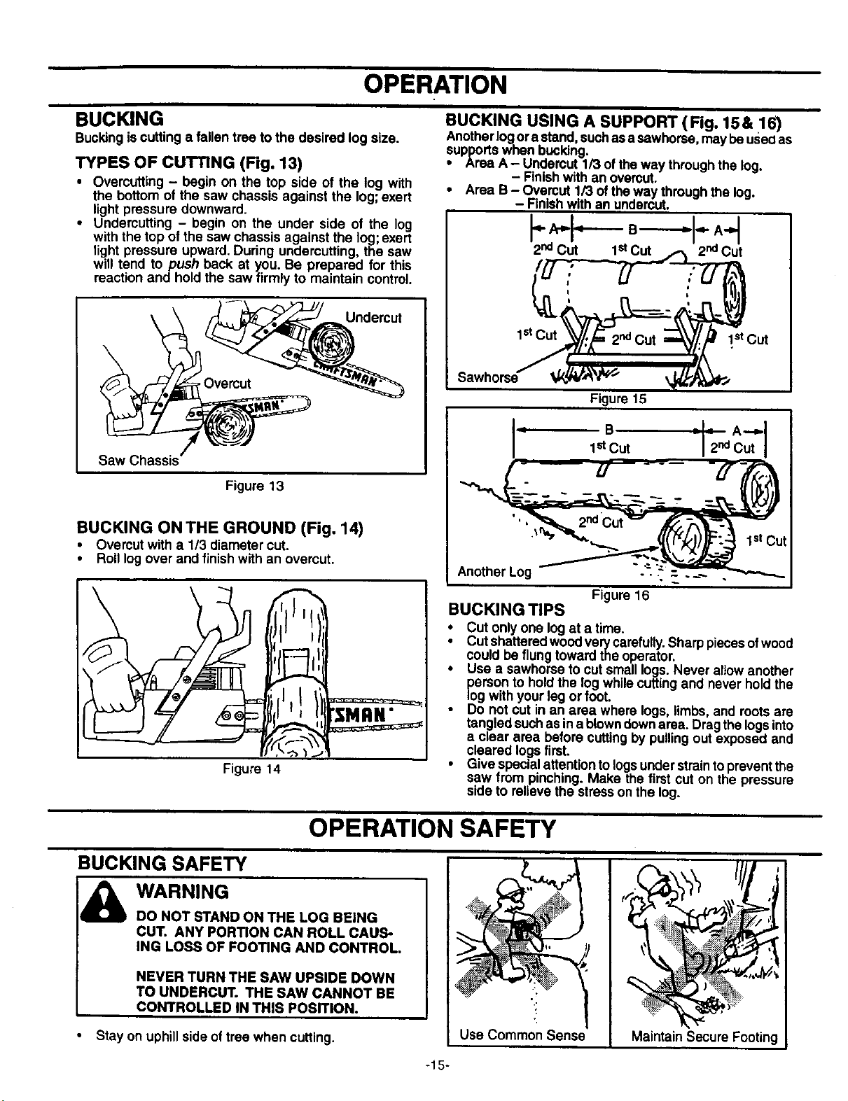
TYPES OF CUTTING (Fig. 13)
• Overcutting - begin on the top side of the log with
the bottom of the saw chassis against the log;exert
light pressure downward.
• Undercutting - begin on the under side of the log
with the top of the saw chassis against the log;exert
light pressure upward. During undercutting, the saw
will tend to push back at you. Be prepared for this
reaction and hold the saw firmly to maintain control.
\
Undercut
Saw Chassis
Figure 13
BUCKING ONTHE GROUND (Fig. 14)
• Overcut with a 1/3 diameter cut.
• Roll logover and finishwith an overcut.
Figure 14
BUCKING USING A SUPPORT (Fig. 15& 16)
Anotherlog.ora stand,suchasa sawhorse, may beuseOas
supportswnen bucking.
• Area A- Undercut 1/3 of the way throughthe log.
- Finishwith an overcut.
• Area B- Overcut 1/3 of theway throughthe log.
- Finishwith an undercut.
ls'C_t_t_ 2ndCut _/:L_ 1.stcut
Figure 15
Another Log "-"-"
Figure 16
BUCKING TIPS
o Cut onlyone log at a time.
Cut shatteredwoodverycarefully.Sharp pieces ofwood
could be flung toward the operator.
Use a sawhorse to cut small logs. Never allowanother
person to holdthe log whilecutting and never holdthe
logwith your leg or foot.
• Do not cut in an area where logs, limbs, and rootsare
tangled suchas in a blown downarea. Dragthe logsinto
a clear area before cuttingby pullingout exposed and
cleared logsfirst.
• Give specialattention to logsunder strainto preventthe
saw from pinching. Make the first cut on the pressure
side to relieve the stresson the log.
OPERATION SAFETY
BUCKING SAFETY
WARNING
DO NOT STAND ON THE LOG BEING
CUT. ANY PORTION CAN ROLL CAUS-
ING LOSS OF FOOTING AND CONTROL.
NEVER TURN THE SAW UPSIDE DOWN
TO UNDERCUT. THE SAW CANNOT BE
CONTROLLED IN THIS POSITION.
• Stay on uphill side of tree when cutting.
Use Common Sense
_._
MaintainSecure Footing
-15-
OPERATION
iii
PRUNING AND LIMBING
Pruning is removing branches from a standing tree.
Limbing is removing branches from a felled tree.
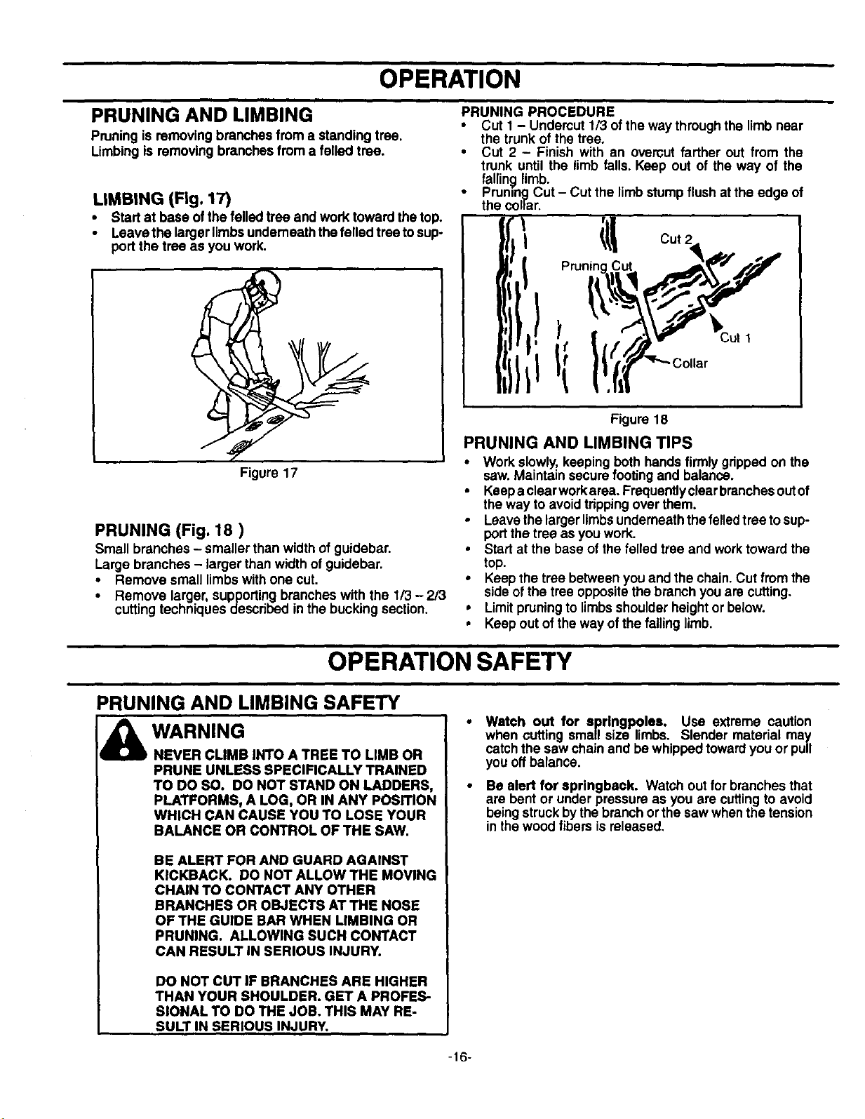
LIMBING (Fig. 17)
• Start at base ofthe felled tree and work toward the top.
• Leave the larger limbsunderneaththe felled treeto sup-
port the tree as you work.
Figure 17
PRUNING (Fig. 18 )
Small branches -smaller than width of guidebar.
Large branches - larger than width of guidebar.
• Remove small limbswith one cut.
• Remove larger, supporting branches with the 1/3 - 2/3
cuttingtechniques described inthe bucking section.
PRUNING PROCEDURE
• Cut I - Undercut 1/3 of theway throughthe limb near
the trunk of the tree.
• Cut 2 - Finish with an ovemut farther out from the
trunk until the limb falls. Keep out of the way of the
falling limb.
• Pruning Cut - Cut the limb stumpflush at the edge of
the collar.
i_ Cut 2
Figure 18
PRUNING AND LIMBING TIPS
• Work slowly, keeping both hands firmlygripped on the
saw. Maintain secure footingand balance.
• Keepa clear workarea. Frequentlyclear brenchesoutof
the way to avoidtrippingover them.
• Leavethe larger limbsunderneaththe felled tree tosup-
portthe tree as you work.
• Start at the base of the felled tree and worktoward the
top.
• Keep the tree between you and the chain. Cut from the
side ofthe tree oppositethe branch you are cutting.
• Limitpruningto limbsshoulderheight or below.
• Keep out of the way ofthe fallinglimb.
OPERATION SAFETY
PRUNING AND LIMBING SAFETY
WARNING
NEVER CLIMB INTO A TREE TO LIMB OR
PRUNE UNLESS SPECIFICALLY TRAINED
TO DO SO. DO NOT STAND ON LADDERS,
PLATFORMS, A LOG, OR IN ANY POSITION
WHICH CAN CAUSE YOU TO LOSE YOUR
BALANCE OR CONTROL OF THE SAW.
BE ALERT FOR AND GUARD AGAINST
KICKBACK. DO NOT ALLOW THE MOVING
CHAIN TO CONTACT ANY OTHER
BRANCHES OR OBJECTS AT THE NOSE
OF THE GUIDE BAR WHEN LIMBING OR
PRUNING. ALLOWING SUCH CONTACT
CAN RESULT IN SERIOUS INJURY.
DO NOT CUT IF BRANCHES ARE HIGHER
THAN YOUR SHOULDER. GET A PROFES-
SIONAL TO DO THE JOB. THIS MAY RE-
SULT IN SERIOUS INJURY.
Watch out for aprlngpolea. Use extreme caution
when cutting small size limbs. Slender material may
catch the saw chain and be whipped towardyou or pull
you offbalance.
Be alert for sprlngbeck. Watch out for branches that
are bent or under pressure as you are cuttingto avoid
beingstruck bythe branch orthe saw whenthe tension
inthe wood fibers isreleased,
-16-
CUSTOMER RESPONSIBILITIES
MAINTENANCE SCHEDULE
Fill in dates as you complete regular service Before After Every Every Yearly Service Dates
Use Use 5 Hrs. 25 Hrs.
Check chain tension
v"
Check chain sharpness
v"
Check guide bar condition
Check guide bar lube
Check for loose fasteners & parts
v"
v"
v" v"
Check for damaged or worn parts
v"
Clean unit& labels
v"
Clean air filter
v"
Clean/inspect spark arrestor screen & inspect muffler
Replace spark plug
v" v"
Replace fuel filter
v"
GENERAL RECOMMENDATIONS
The warranty on this unit does not cover items that have
been subjected to operator abuse or negligence. To
receive full value from the warranty, the operator must
maintain unitas instructed in this manual.
Some adjustments will need to be made periodically to
properly maintain your unit.
Alladjustmentsin the "Service and Adjustments"sectionof
this manualshouldbe checked at least once each season.
• Once a year, replace the spark plug, replace air filter
element and check guide bar and chain for wear.A new
spark plug and a clean/new air filter element assures
proper air-fuel mixture and helpsyour engine run better
and lastlonger.
Followthe maintenance schedule in this manual.
_b WARNING i
DISCONNECTTHE SPARK PLUG BEFORE i
PERFORMING MAINTENANCE EXCEPT!
FOR CARBURETOR ADJUSTMENTS. !
INSPECT THE ENTIRE UNIT. REPLACE
DAMAGED PARTS. CHECK FOR FUEL
LEAKS AND MAKE SURE ALL FASTEN-
ERS ARE IN PLACE AND SECURELY FAS-
TENED.
LUBRICATION CHART
CRRFTSMR
(DCraftsman chain saw bar oil
® Craftsman bar sprocket lube
BEFORE EACH USE
• Check chain tension
• Check chain sharpness
• Check guide bar condition
• Check guide bar lube
• Check for loose fasteners & parts
• Check for damaged or wornparts
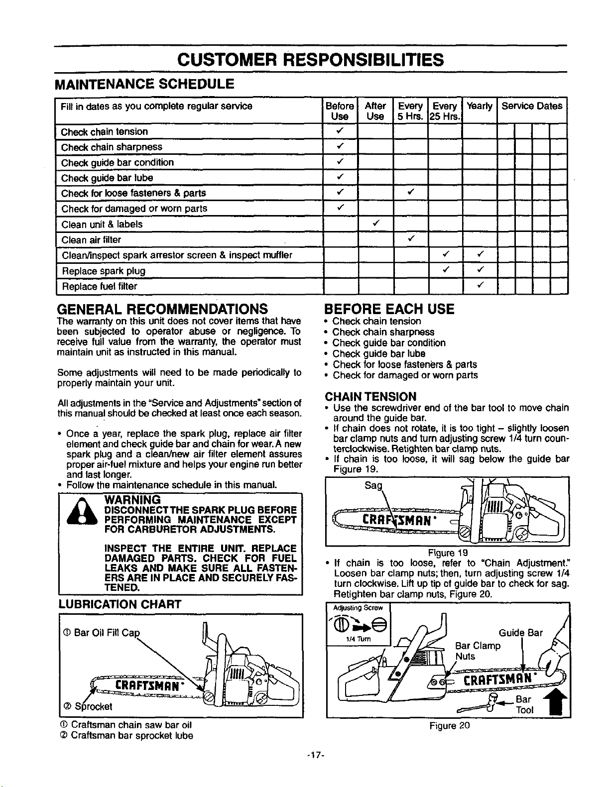
CHAIN TENSION
• Use the screwdriver end of the bar tool to move chain
around the guide bar.
• If chain does not rotate, it is too tight- slightlyloosen
bar clamp nuts and turn adjustingscrew 1/4 turn coun-
temlockwise. Retighten bar clamp nuts.
• If chain is too loose, it will sag below the guide bar
Figure 19.
Figure 19
• If chain is too loose, refer to "Chain Adjustment."
Loosen bar clamp nuts; then, turn adjusting screw 1/4
turn clockwise. Lift up tip of guide bar to check for sag.
Retighten bar clamp nuts, Figure 20.
Adjusting Screw
,,,Turn I F,//._f Bar ClampGUidi Bar '
Bar"I[
Tool /
Figure 20
o17-
CUSTOMER RESPONSIBILITIES
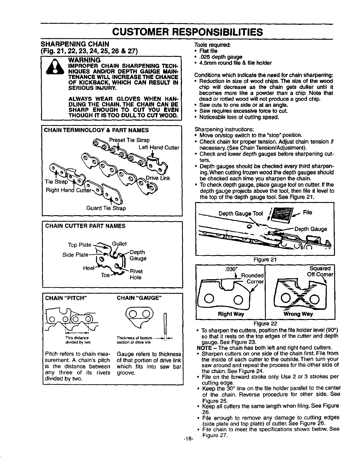
SHARPENING CHAIN
(Fig. 21,22, 23, 24, 25, 26 & 27)
_ ARNING
IMPROPER CHAIN SHARPENING TECH-
NIQUES AND/OR DEPTH GAUGE MAIN-
TENANCE WILL INCREASE THE CHANCE
OF KICKBACK, WHICH CAN RESULT IN
SERIOUS INJURY.
ALWAYS WEAR GLOVES WHEN HAN-
DLING THE CHAIN. THE CHAIN CAN BE
SHARP ENOUGH TO CUT YOU EVEN
THOUGH IT ISTOO DULLTO CUT WOOD.
Toolsrequired:
• Flat file
• .025 depth gauge
• 4.5mm roundfile & file holder
Conditionswhichindicate the need for chainsharpening:
• Reduction in size of wood chips.The size of the wood
chip will decrease as the chain gets duller"until it
becomes more like a powder than a chip. Note that
dead or rotted woodwill not produce a good chip.
• Saw cutsto one side or at an angle.
• Saw requires excessiveforce to cut.
• Noticeable loss of cuttingspeed.
CHAIN TERMINOLOGY & PART NAMES
Preset Tie Strap
Left Hand Cutter
___,_ Drive Link
Right Hand Cut_;r_ --
Guard Tie Strap
CHAIN CUTTER PART NAMES
Top Plate ._,..,..,_._G,ullet
Side Plate_-_/_DeP;e
CHAIN "PITCH" CHAIN"GAUGE"
This distance Thickness of boitorn _
divideClby tw_ section of drive link
Pitch refers to chain mea-
surement. A chain's pitch
is the distance between
any three of its rivets
divided by two.
Gauge refers to thickness
of that portion of drive link
which fits into saw bar i
groove.
Sharpening instructions:
• Move on/stop switchto the "stop" position.
• Check chain for proper tension.Adjust chain tension if
necessary.(See Chain Tension/Adjustment).
• Check and lowerdepth gauges before sharpening cut-
ters.
• Depth gauges should be checked every third sharpen-
ing.When cutting frozen wood the depth gauges should
be checked each time you sharpen the chain.
• To check depth gauge, place gauge tool on cutter. If the
depth gauge projects above the tool, then file it level to
the top of the depth gauge tool. See Figure 21.
-18-
Figure 21
.030"
_1 Rounded
Right Way
O-Y_O
Wrong Way
Figure 22
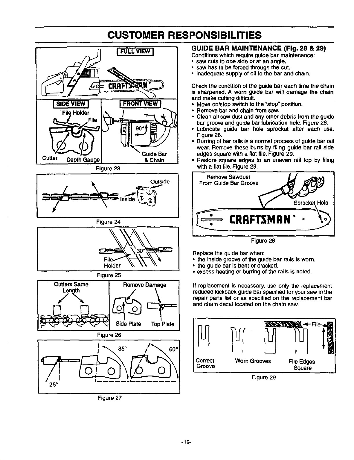
• To sharpen thecutters,position the file holder level (90°)
so that it rests on the top edges of the cutter and depth
gauge. See Figure 23.
NOTE - The chain has both leftand righthand cutters.
• Sharpen cutters on one side of the chain first. File from
the inside of each cutter to the outside.Then turn your
saw around and repeat the process for the other side of
the chain. See Figure 24.
• File on the forward stroke only. Use 2 or 3 strokes per
cutting edge.
• Keep the 30° line on the file holder parallelto the center
of the chain. Reverse procedure for other side. See
Figure 25.
• Keep all cutters the same length when filing. See Figure
26.
• File enough to remove any damage to cutting edges
(side plate and top plate) of cutter.See Figure 26.
• File chain to meet the specificationsshown below. See
Figure 27.
CUSTOMER RESPONSIBILITIES
I SIDe VIEW ]
File Holder
__/...,__ File
Cutter Depth Gauge
I FRONT VIEW
"_ Guide Bar
&Chain
Figure 23
Outside
_ "--_---"-.-_ -- Inside _,_
Cutters Same
Figure 24
Figure 25
Remove Damage
Side Plate TopPlate
Figure 26
I 85°
J
I
I
I
25°
GUIDE BAR MAINTENANCE (Fig. 28 & 29)
Conditionswhich require guide bar maintenance:
• saw cuts to one side or at an angle.
• saw has to be forced through the cut.
• inadequate supply of oilto the bar and chain.
Check the conditionof the guide bar each time the chain
is sharpened. A worn guide bar will damage the chain
and make cuttingdifficult.
• Move on/stopswitch to the "stop"position.
• Remove bar and chain from saw.
• Clean all saw dust and any other debris from the guide
bar groove and guide bar lubrication hole. Figure 28.
• Lubricate guide bar hole sprocket after each use.
Figure 28.
• Burringofbar railsis a normal process of guide bar rail
wear. Remove these burrs by filing guide bar rail side
edges square with a flat file. Figure 29.
• Restore square edges to an uneven rail top by filing
with a flat file. Figure 29.
Remove Sawdust
From Guide Bar Groove
CRRFTSMRN""
Figure 28
Replace the guide bar when:
• the inside groove of the guide bar rails is worn.
• the guide bar is bent or cracked.
• excess heating or burring ofthe rails is noted.
If replacement is necessary, use only the replacement
reduced kickback guide bar specified for yoursaw in the
repair parts list or as specified on the replacement bar
and chain decal located on the chain saw.
Correct Wom Grooves File Edges
Groove Square
Figure 29
Figure 27
-19-
CUSTOMER RESPONSIBILITIES
CHECK FOR DAMAGED/WORN PARTS
The followingdamaged/worn parts should be referred to
your Sears Service Center.
NOTE: It is normal for a small amount of oil to appear
under the saw after engine stops.Do not confusethis with
a leakino oiltank.
• On/Stop Switch - ensure on/stopswitchfunctionsprop-
erly by moving the switch to the =Stop"position and
assure that engine stops, then restartyour engine and
continue.
• Fuel Tank - discontinue use of chain saw if fuel tank
show signsof damage or leaks.
• Oil Tank- discontinue use of chainsaw ifoiltankshows
signs ofdamage or leaks.
• Chain Catcher - replace chain catcher if bent, cut, or
damaged in any way.
CLEAN UNIT AND LABELS
• Clean the unitusinga damp clothwitha milddetergent.
• Wipe off the unitwith a clean dry cloth.
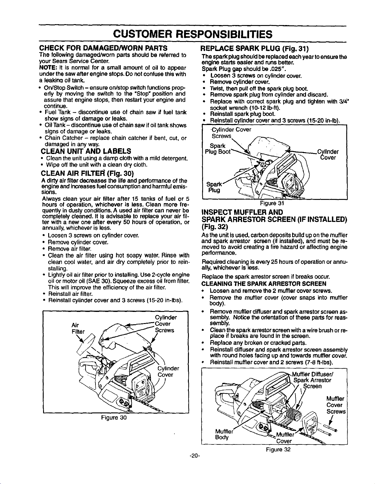
CLEAN AIR FILTE_ (Fig. 30)
A dirtyair filterdecreases the life and performance of the
engineand increasesfuelconsumptionand harmfulemis-
sions.
Always clean your air filter after 15 tanks of fuel or 5
hours of operation, whichever is less. Clean more fre-
quently in dustyconditions.A used air filtercan never be
completelycleaned. It is advisable to replace your air fil-
ter with a new one after every 50 hours of operation, or
annually,whichever is less.
• Loosen 3 screws on cylindercover.
• Remove cylinder cover.
• Remove air filter.
• Clean the air filter using hot soapy water. Rinse with
clean cool water, and air dry completely prior to rein-
stalling.
• Lightly oil air filter prior to installing. Use 2-cycle engine
oil or motor oil (SAE 30). Squeeze excess oil from filter.
This willimprove the efficiency of the air filter.
• Reinstall air filter.
• Reinstall cylinder cover and 3 screws (15-20 in-lbs).
Cylinder
Air 3over
Filter :rews
Cylinder
Cover
Figure '30
REPLACE SPARK PLUG (Fig, 31)
The spark plugshouldbereplacedeachyear toensurethe
engine starts easier and runsbetter.
Spark Plug gap shouldbe .025".
• Loosen 3 screws on cylindercover.
• Remove cylindercover.
• Twist,then pulloffthe spark plug boot.
• Remove spark plugfromcylinderand discard.
• Replace with correct spark plug and tighten with 3/4"
socket wrench (10-12 Ib-ft).
• Reinstall spark plugboot.
Reinstallcylindercover and 3 screws(15-20 in-lb).
Cylinder Cover
Screws
-20-
Figure31
INSPECT MUFFLER AND
SPARK ARRESTOR SCREEN (IF INSTALLED)
(Fig. 32)
Asthe unitisused, carbondepositsbuildupon themuffler
and spark arrestor screen (if installed),and must be re-
moved to avoid creating a fire hazard or affecting engine
performance.
Required cleaning isevery 25 hoursofoperationor annu-
ally,whichever is less.
Replace the spark arrestor screen ifbreaks occur.
CLEANING THE SPARK ARRESTOR SCREEN
• Loosen and remove the 2 mufflercover screws.
• Remove the muffler cover (cover snaps into muffler
body).
• Remove muffler diffuserand sparkarrestor screen as-
sembly. Notice the orientationofthese parts for reas-
sembly.
• Clean the sparkarrestorscreenwitha wire brushorre-
place ifbreaks are foundin the screen.
• Replace any brokenor cracked parts.
• Reinstall diffuser and spark arrestor screen assembly
with round holesfacingup and towards mufflercover.
• Reinstall mufflercover and 2 screws(7-8 ft-lbs).
Muffler
Body
_Muffler Diffuser/
_'_S Pa_ rA'_eeSt°r
G/ Z ,.u.,o,
_,.,_/j ,_/ Cover
Muffler _
Cover
Figure 32
CUSTOMER RESPONSIBILITIES
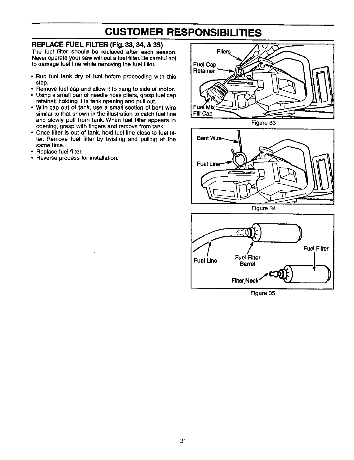
REPLACE FUEL FILTER (Fig. 33, 34, & 35)
The fuel filter should be replaced after each season.
Never operate your saw withouta fuel filter. Be careful not
to damage fuel line while removingthe fuel filter.
• Run fuel tank dry of fuel before proceeding with this
step.
• Remove fuel cap and allow itto hang to side of motor.
• Using a small pair ot needle nose pliers, graspfuel cap
retainer, holding it in tank opening and pull out.
• With cap out of tank, use a small section of bent wire
similar to that shown inthe illustrationto catch fuel line
and slowly pull from tank. When fuel tilter appears in
opening, grasp with fingers and remove from tank.
• Once filter is out of tank, hold fuel line close to fuel fil-
ter. Remove fuel filter by twisting and pulling at the
same time.
• Replace fuel filter.
• Reverse process for installation.
Fill Cap
Figure 33
Fuel Line
Figure 34
Fuel Filter
Barrel
Filter Neck*''_ I_
Figure 35
Fuel Filter
"21-
SERVICE AND ADJUSTMENTS
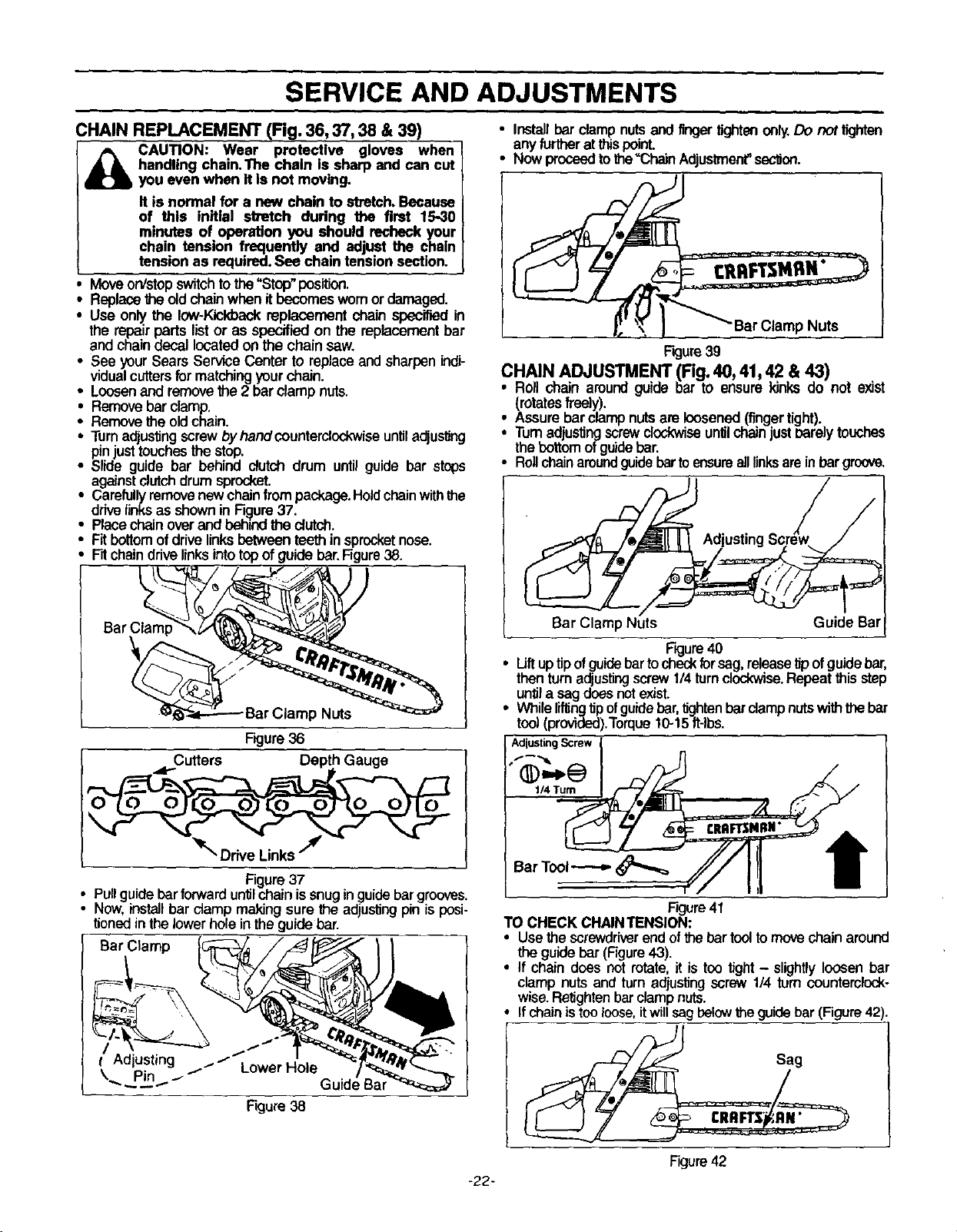
CHAIN REPLACEMENT (Fig_.36, 37, 38 & 39)
CAUTION: Wear protective gloves when
handling chain.The chain is sharp and can cut
you even when it Is not moving.
It is normal for a new chain to stretch.Because
of this initial stretch during the first 15-30
minutes of operation you should recheck your
chain tension frequently and adjust the chain
tension as required.See chaintension section.
Move on/stop switch to the "Stop" position.
Replacegle old chain when it becomes wornor damaged.
• Use only.the low-Kickback replacement chain specified in
the repair parts list or as specified on the replacement bar
and chain decal located on the chain saw.
• See your Sears Service Center to replace and sharpen indi-
vidual cutters for matching your chain.
• Loosen and remove the 2 bar clamp nuts.
• Remove bar clamp.
• Remove theold chain.
i Turnadjusting screw byhand oeunterclodoNiseuntiladjusting
pin ust touches the stop.
Slide guide bar behind dutch drum until guide bar stops
against clutch drum sprocket.
• Carefullyremovenew chain from package.Holdchainwith the
ddve linksas shownin F_ure 37.
Placechainoverand behindthe clutch.
Fit bottomofdrivelinksbetweenteethinsprocketnose.
Fitchaindrivelinksintotopofguide bar.Figure38.
Bar Clam[
Nuts
Figure36
O_"=wCutters Depth Gauge ]l
Figure37
Pullguidebarforward untilchainissnug inguidebar grooves.
Now,installbar damp makingsure _e adjustingpinisposi-
tionedinthe lower holeintheguidebar.
Bar Clamp
Adjusting ..-/ Lower Hole
\.......Pin J'/ Guide Bar
Figure38
• Install bar clamp nuts and fingertightenonly.Do not fightan
anyfurther at this point.
• Nowproceedtothe"Chain Adjustmenf'seclJon.
CRRFTSMRN"
'Bar Clamp Nuts
F'_ure39
CHAIN ADJUSTMENT (Fig. 40, 41, 42 & 43) . .
• Roll chain around guide bar to ensure kinks do no[ exist
(rotatesfreoly).
Assure bar clamp nuts are loosened(fingertight).
Turn adjustingscrewclockwiseuntil chainjust _rely touches
the bottom of guidebar.
• Rollchainaroundguidebartoensurealllinksarein bar groove.
Bar Clamp Nuts Guide Bar
Figure40
i Uft uptip ofguidebartocheokforsag, releasetip ofguidebar,
then turnadjustingscrew1/4turnclo_wise. Repeat _is step
untila sagdoesnotexist.
While I_ng tipofguidebar,tightenbar clamp nutswith the bar
tool (provided).Torque10-15ft-lbs.
AdjustingScrew
Bar Tool_
/
Figure41
TO CHECK CHAINTENSION:
• Usethe screwdriverend ofthebar tool tomove chain around
the guidebar (Figure43).
• If chain does not rotate,it is too tight - slightlyloosen bar
clamp nutsand turnadjustingscrew1/4 turncountemlock-
wise.Retightenbar clampnuts.
If chainis tooloose,itwillsagbelow_e guidebar (Figure42).
Figure42
-22-
SERVICE AND ADJUSTMENTS
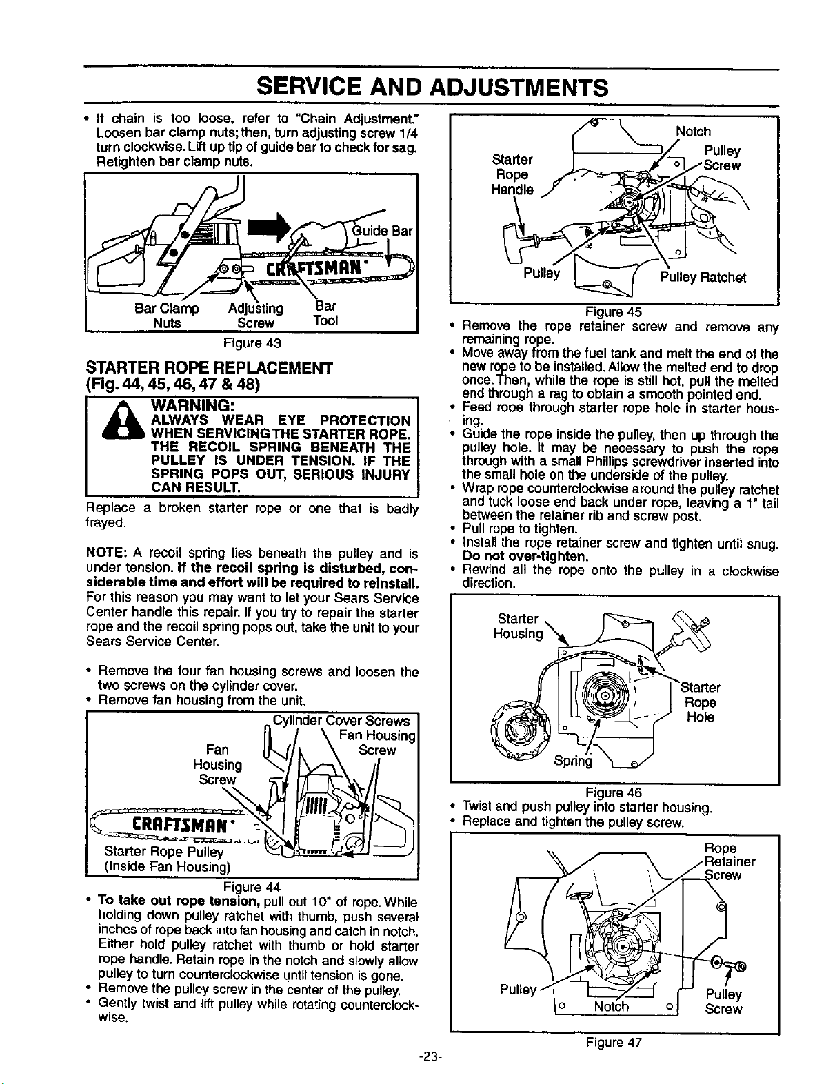
• If chain is too loose, refer to "Chain Adjustment."
Loosen bar clamp nuts;then, turnadjusting screw 1/4
turn clockwise. Lift up tip of guide bar to check for sag.
Retighten bar clamp nuts.
Bar Clamp Bar
Nuts Screw Tool
Figure 43
STARTER ROPE REPLACEMENT
(Fig. 44, 45, 46, 47 & 48)
WARNING:
ALWAYS WEAR EYE PROTECTION
WHEN SERVICING THE STARTER ROPE.
THE RECOIL SPRING BENEATH THE
PULLEY IS UNDER TENSION. IF THE
SPRING POPS OUT, SERIOUS INJURY
CAN RESULT.
Replace a broken starter rope or one that is badly
frayed.
NOTE: A recoil spring lies beneath the pulley and is
under tension. If the recoil spring is disturbed, con-
siderable time and effort will be required to reinstall.
For this reason you may want to letyour Sears Service
Center handle this repair. If you try to repair the starter
rope and the recoil spring popsout, take the unitto your
Sears Service Center.
• Remove the four fan housing screws and loosen the
two screws on the cylinder cover.
Remove fan housing from the unit.
,,Cylinder Cover Screws
II / \ Fan Housing
Fan HL.. _k \ Screw
Housing "-_" Jl
Screw
(Inside Fan Housing) i
I
Figure 44
• To take out rope tension, pull out 10" of rope.While
holding down pulley ratchet with thumb, push several
inches of rope back into fan housing and catch in notch.
Either hold pulley ratchet with thumb or hold starter
rope handle. Retain rope in the notch and slowly allow
pulley to turn counterclockwise until tension is gone.
• Remove the pulley screw in the center of the pulley.
• Gently twist and lift pulley while rotating counterclock-
wise.
Starter
Rope
Handle
Notch
Pulley
Pulley Pulley Ratchet
Figure 45
• Remove the rope retainer screw and remove any
remaining rope.
• Move away from the fuel tank and melt the end of the
new ropeto be installed.Allowthe melted end to drop
once.Then, while the rope is still hot, pull the melted
end through a rag to obtain a smooth pointed end.
• Feed rope through starter rope hole in starter hous-
ing.
• Guide the rope inside the pulley,then up through the
pulley hole. It may be necessary to push the rope
through with a small Phillipsscrewdriver inserted into
the small hole on the underside of the pulley.
• Wrap rope counterclockwisearound the pulley ratchet
and tuck loose end back under rope, leaving a 1" tail
between the retainer rib and screw post.
• Pull ropeto tighten.
• Install the rope retainer screw and tighten until snug.
Do not over-tighten.
• Rewind all the rope onto the pulley in a clockwise
direction.
Starter \
Housing"_k
Rope
Hole
Figure 46
• Twist and push pulley into starter housing.
Replace and tighten the pulleyscrew.
o Notch o
Rope
_er
Pulley
Screw
Figure 47
-23-
SERVICE AND ADJUSTMENTS
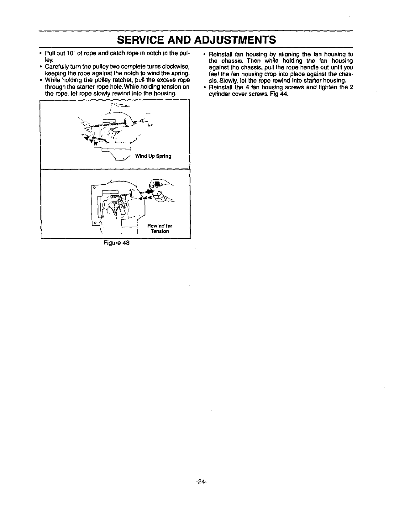
• Pullout 10" of rope and catch rope in notchin the pul-
ley.
• Carefullyturn the pulley twocomplete turnsclockwise,
keeping the rope against the notchto wind the spring.
• While holdingthe pulley ratchet, pullthe excess rope
throughthe starter ropehole.While holdingtension on
the rope, let rope slowly rewind intothe housing.
• Reinstall fan housing by aligning the fan housing to
the chassis. Then while holding the fan housing
against the chassis,pull the rope handle out until you
feel the fan housing drop into place against the chas-
sis. Slowly, let the rope rewind into starter housing.
• Reinstall the 4 fan housing screws and tighten the 2
cylinder cover screws.Fig 44.
Wind Up Spring
Figure 48
-24-
SERVICE AND ADJUSTMENTS
CARBURETOR PRESETS (Fig. 49)
CARBURETOR ADJUSTMENTS
Carburetor adjustment Is critical and if done improp-
erly can permanently damage the engine as well as
the carburetor. Please read all instructions and con-
sult the Troubleshooting section of this manual
before beginning this process.
WARNING:
THE CHAIN WILL BE MOVING DURING
MOST OF THIS PROCEDURE. WEAR
YOUR PROTECTIVE EQUIPMENT AND
OBSERVE ALL SAFETY PRECAUTIONS.
IN "LOW SPEED MIXTURE ADJUST°
MENT," RECHECK IDLE SPEED AFTER
EACH ADJUSTMENT. THE CHAIN MUST
NOT MOVE AT IDLE SPEED.
ITengine does not start, it may be flooded. If in doubt,
read the section on flooded engine in the starting section
of this manual prior to beginning any adjustments.
If you are unsure about adjusting the carburetor or expe-
rience any problem while attempting this process, please
call the 1-800 number listed on the front cover of this
manual for further assistance.
The carburetor has been adjusted at the factory for sea
level conditions. Adjustments may become necessary if
the saw is used at significantly higher altitudes or if you
notice any of the following conditions:
• Chain moves when the engine runs at idle speed. See
"Idle Speed Adjustment."
• Saw will not idle. See "Idle Speed Adjustment" and =Low
Speed Mixture Adjustment."
• Engine dies or hesitates when it should accelerate. See
"Acceleration Adjustment."
• Loss of cutting power which is not corrected by air filter
cleaning. See "High Speed Mixture Adjustment."
NOTE: Your chain saw carburetor isequipped with limiter
caps. Do not attempt to adjustthe mixturescrews beyond
the stops as damage can occur.
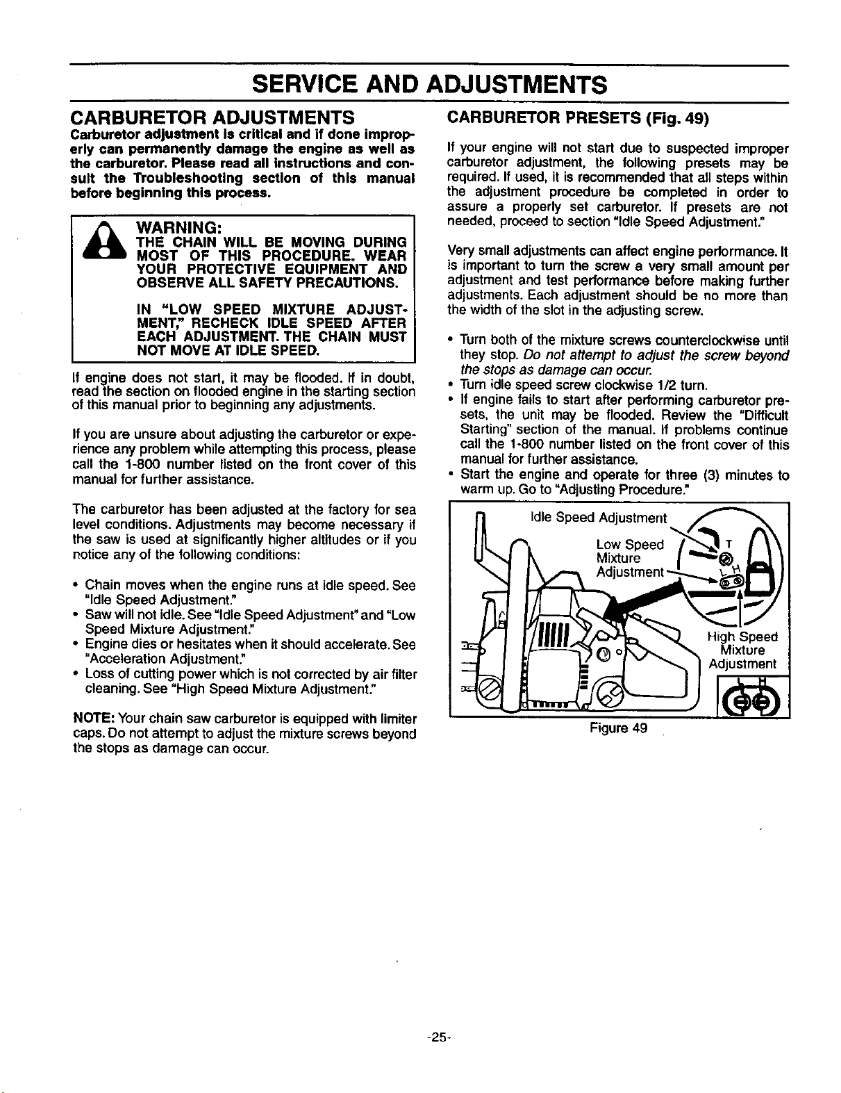
If your engine will not start due to suspected improper
carburetor adjustment, the following presets may be
required.If used, it is recommended that all steps within
the adjustment procedure be completed in order to
assure a properly set carburetor. If presets are not
needed, proceed to section"Idle Speed Adjustment."
Very small adjustments can affect engine performance. It
is important to turn the screw a very small amount per
adjustment and test performance before making further
adjustments. Each adjustment should be no more than
the widthof the slot in the adjusting screw.
• Turn both of the mixture screws counterclockwise until
they stop.Do not attempt to adjust the screw beyond
the stops as damage can occur.
• Turn idle speed screw clockwise 1/2 turn.
• If engine fails to start after performing carburetor pre-
sets, the unit may be flooded. Review the =Difficult
Starting"section of the manual. If problems continue
call the t-800 number listed on the front cover of this
manual for further assistance.
• Start the engine and operate for three (3) minutes to
warm up.Go to "Adjusting Procedure."
Idle Speed Adjustment
Low Speed
Mixture
Adj
Figure 49
High Speed
Mixture
Adjustment
-25-
SERVICE AND ADJUSTMENTS
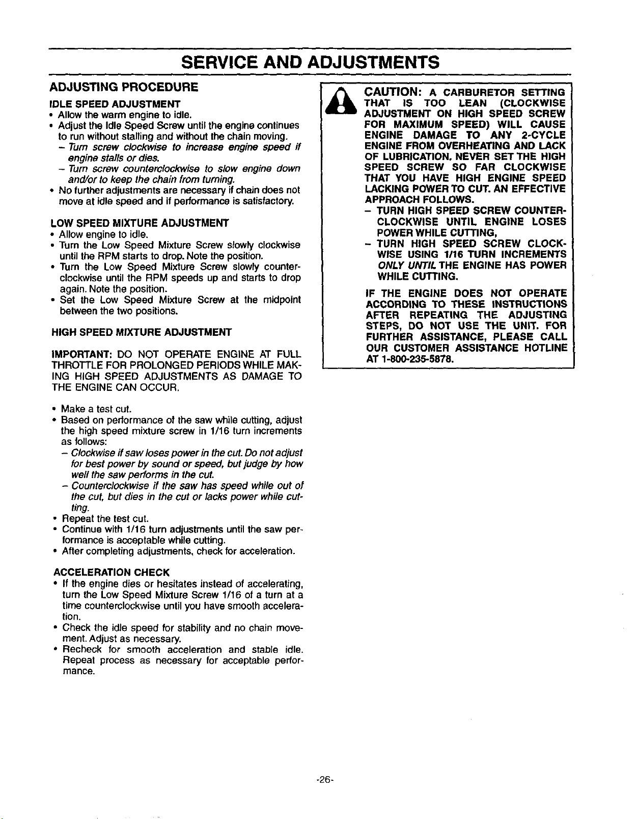
ADJUSTING PROCEDURE
IDLE SPEED ADJUSTMENT
• Allow the warm engine to idle.
• Adjust the Idle Speed Screw untilthe engine continues
to runwithout stalling and without the chain moving.
- Turn screw clockwise to increase engine speed ff
engine stalls or dies.
- Turn screw counterclockwise to slow engine down
and/or to keep the chain from turning.
• No further adjustments are necessary ifchain does not
move at idle speed and if performance is satisfactory.
LOW SPEED MIXTURE ADJUSTMENT
• Allow engine to idle.
• Turn the Low Speed Mixture Screw slowly clockwise
until the RPM starts to drop.Note the position.
• Turn the Low Speed Mixture Screw slowly counter-
clockwise untilthe RPM speeds up and starts to drop
again. Note the position.
• Set the Low Speed Mixture Screw at the midpoint
between the two positions.
HIGH SPEED MIXTURE ADJUSTMENT
IMPORTANT: DO NOT OPERATE ENGINE AT FULL
THROTTLE FOR PROLONGED PERIODS WHILE MAK-
ING HIGH SPEED ADJUSTMENTS AS DAMAGE TO
THE ENGINE CAN OCCUR.
CAUTION: A CARBURETOR SETTING
THAT IS TOO LEAN (CLOCKWISE
ADJUSTMENT ON HIGH SPEED SCREW
FOR MAXIMUM SPEED) WILL CAUSE
ENGINE DAMAGE TO ANY 2-CYCLE
ENGINE FROM OVERHEATING AND LACK
OF LUBRICATION. NEVER SET THE HIGH
SPEED SCREW SO FAR CLOCKWISE
THAT YOU HAVE HIGH ENGINE SPEED
LACKING POWER TO CUT. AN EFFECTIVE
APPROACH FOLLOWS.
- TURN HIGH SPEED SCREW COUNTER-
CLOCKWISE UNTIL ENGINE LOSES
POWER WHILE CUTTING,
- TURN HIGH SPEED SCREW CLOCK-
WISE USING 1/16 TURN INCREMENTS
ONLY UNTIL THE ENGINE HAS POWER
WHILE CUTTING.
IF THE ENGINE DOES NOT OPERATE
ACCORDING TO THESE INSTRUCTIONS
AFTER REPEATING THE ADJUSTING
STEPS, DO NOT USE THE UNIT. FOR
FURTHER ASSISTANCE, PLEASE CALL
OUR CUSTOMER ASSISTANCE HOTLINE
AT 1-800-235-5878.
• Make a test cut.
• Based on performance of the saw while cutting,adjust
the high speed mixture screw in 1/16 turn increments
as follows:
- Clockwise if saw loses power in the cut. Do not adjust
for best power by sound or speed, but judge by how
well the saw performs in the cut.
- Counterclockwise ff the saw has speed while out of
the cut, but dies in the cut or lacks power while cut-
ting.
• Repeat the test cut.
• Continue with 1/16 turn adjustments until the saw per-
formance is acceptable while cutting.
• After completing adjustments, check for acceleration.
ACCELERATION CHECK
• If the engine dies or hesitates instead of accelerating,
turn the Low Speed Mixture Screw 1/16 of a turn at a
time counterclockwiseuntil you have smooth accelera-
tion.
• Check the idle speed for stability and no chain move-
ment. Adjust as necessary.
• Recheck for smooth acceleration and stable idle.
Repeat process as necessary for acceptable perfor-
mance.
-26-
STORAGE
Immediately prepare your unit for storage at the end of
the season or if itwill not be used for 30 days or more.
_ ARNING: I
ALLOW THE ENGINE TO COOL, AND
SECURE THE UNIT BEFORE STORING
OR TRANSPORTING IN A VEHICLE.
STORE UNIT AND FUEL IN AN AREA
WHERE FUEL VAPORS CANNOT REACH
SPARKS OR OPEN FLAMES FROM
WATER HEATERS, ELECTRIC MOTORS
OR SWITCHES, FURNACES, ETC.
STORE UNIT WITH ALL GUARDS IN
PLACE. POSITION SO THAT ANY SHARP
OBJECT CANNOT ACCIDENTALLY
CAUSE INJURYTO PASSERS BY.
STORE THE UNIT OUT OF THE REACH
OF CHILDREN.
GAS CHAIN SAW STORAGE INSTRUCTIONS
If your chain saw isto be storedfor a period oftime, clean
itthoroughly prior to storage. Remove any dirt, sawdust,
leaves, oil, grease, etc.Store in a clean dry area.
• Clean the entire unit.
• Clean air filter.Refer to "Customer Responsibilities:
• Inspect the bar clamp area and clean any dirt, sawdust,
grass, or debris that has collected. Inspect the guide
bar and chain;replace a guide bar that is bent, warped,
cracked, broken, or damaged in any other way.Replace
a damaged or worn chain.
• Lightly oil external metal surfaces to prevent rust from
forming.
I_ CAUTION: Wear protective gloves when
handling chain. The chain is sharp and
can cut you even when it is not moving.
• Apply a coating of oilto the entire surface of the guide
bar and chain;wrap it in heavy paper, or cloth.
• Be sure all handles and guards are in place and are
securely fastened. Replace any damaged parts.
FUEL SYSTEM
Never use engine or carburetor cleaner products in the
fuel tank or permanent damage may occurto fuel system
components. Followthese instructions:
• Drain the fuel from the unit into an approved fuel con-
tainer.
• Drain the fuel lines and carburetor by starting the
engine and letting it run untilit stops.
• Allow the engine to cool before storage.
IMPORTANT: It is important to prevent gum deposits
from forming in essential fuel system parts such as the
carburetor, fuel filter, fuel hose or tank dudng storage.
Also, experience indicates that alcohol blended fuels,
those that use ethanol or methanol (called gasohol or
oxygenated fuel), can attract moisture and form acidic
gaswhichwilldamage yourengine.To avoid engine prob-
lems, the fuel system should be emptied before storage
of 30 days or longer.
Fuel stabilizer is an acceptable alternative in minimizing
the formation of fuel gum deposits during storage. Add
stabilizer to the gasoline in the fuel tank or fuel storage
container.Always follow the mix instructionsfound on sta-
bilizer containers. Run engine at least 5 minutes after
adding stabilizer to allow the stabilizer to reach the car-
buretor.
CRAFTSMAN 40:1 2-cycle engine oil (AIR-COOLED) is
specially blended with fuel stabilizer. If you do not use
this Sears oil, you can add a fuel stabilizer to your fuel
tank.
INTERNAL ENGINE
• Remove spark plug and pour 1 teaspoon of 40:1 2-
cycle engine oil (AIR-COOLED) through the spark plug
opening. Slowly pull the starter rope 8 to 10 times to
distributeoilto inner engine surfaces.
• Replace spark plug with a new one of the recommend-
ed type and heat range. Refer to =Product Specifica-
tions."
• Clean air filter. Refer to "Customer Responsibilities."
• Re-install all covers and hardware removed for access;
tighten all screws and fasteners.
• Check entire unit for loose screws, nuts, and bolts.
Replace any damaged, broken, or worn parts.
• Lightly oil external metal surface to prevent rust from
forming.
• Use fresh fuel having the proper gasoline to oil ratio at
the beginning of the next season.
OTHER
• Do not store gasoline from one season to another.
• Replaceyourgasoline can ifyour can startsto rust.Rust
and/or dirtin your fuel system will cause problems.
• Store your unit in a well ventilated area and covered, if
possible,to prevent dust and dirtaccumulation. Do not
cover with plastic. Plastic cannot breathe and will
induce condensation and eventual rust or corrosion.
IMPORTANT: NEVER COVER UNIT WHILE ENGINE
AND EXHAUST AREAS ARE STILL WARM.
-27-
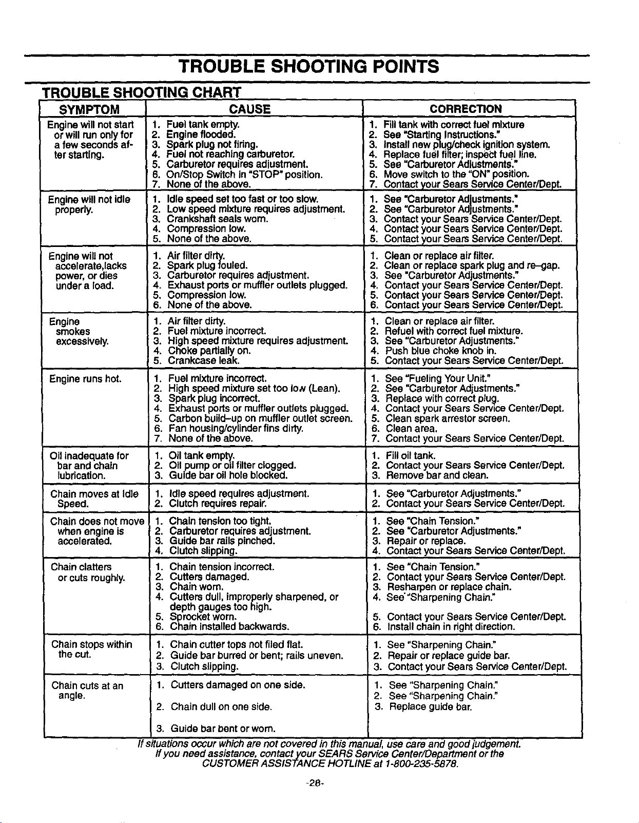
TROUBLE SHOOTING POINTS
TROUBLE SHOOTING CHART
SYMPTOM
Engine will not start
or will run onlyfor
a few seconds af-
ter starting.
Engine will not idle
properly.
Engine will not
accelerate,lacks
power, or dies
under a load.
Engine
smokes
excessively•
Engine runshot.
Oil inadequate for
bar and chain
lubdcation.
Chain moves at Idle
Speed.
Chain does not move
when engine is
accelerated.
Chain clatters
or cuts roughly.
I' Chain stopswithin
the cut.
CAUSE
1. Fuel _ank empty. "
2. Engine flooded.
3. Spark plug notfidng.
4. Fuel not reaching carburetor.
5. Carburetor requiresadjustment.
6. On/Stop Switch in =STOP" position•
7. None of the above.
1. Idle speed set too fast or too slow.
2. Low speed mixturerequires adjustment,
3. Crankshaft seals worn.
4. Compression low.
5. None ofthe above.
1. Airfilter dirty.
2. Spark plug fouled.
3. Carburetor requiresadjustment.
4. Exhaust portsor muffleroutlets plugged•
5. Compression low.
I 6. None of the above.
1 Air filterdirty.
Fuel mixtureincorrect.
3. High speed mixturerequires adjustment.
4. Choke partiallyon.
5. Crankcase leak.
1. Fuel mixtureincorrect.
il igh speed mixture set too Io,v(Lean).
Spark plug incorrect.
• Exhaust portsor muffleroutlets plugged.
5. Carbon build-up on muffler outletscreen.
6. Fan housing/cylinderfins dirty.
7. None of the above.
1. Oil tank emp_.
2. Oil pump or odfilterclogged•
3. Guide bar oil hole blocked.
1. Idle speed requiresadjustment.
2. Clutch requiresrepair•
1. Chain tension too tight.
2. Carburetor requiresadjustment.
3. Guide bar railspinched.
4. Clutch slipping.
1. Chain tension incorrect.
2. Cutters damaged.
3. Chain worn.
4. Cutters dull,improperlysharpened, or
depth gauges too high.
5. Sprocket worn.
6. Chain installedbackwards.
CORREC_ON
1. Fill tank with correctfuel mixture
2. See "StartingInstructions."
3. Installnew plug/check ignitionsystem.
4. Replace fuel filter;inspectfuel hne.
5. See =Carburetor Adlustments,"
6. Move switchto the "ON"position.
7. Contactyour Sears Service Canter/Dept.
1. See "CarburetorAd_LJstments."
2. See =CarburetorAd ustments."
3. Contact yourSears' 3ervica Center/Dept.
4. Contact your Sears ServiceCenter/Dept.
5, Contact your Sears ServiceCenter/Dept.
1. Clean or replace air filter.
2. Clean or replace spark plugand re-gap,
3. See "CarburetorAdjustments."
4. Contact your Sears Service Center/Dept.
5, Contact your Sears Service Center/Dept.
6. Contactyour Sears Service Center/Dept:.
1. Clean or replace air filter.
2. Refuel with correctfuel mixture.
3. See -carburetor Adjustments."
4. Push bluechoke knob in.
5. Contact your Sears ServiceCenter/Dept.
1. See =FuelingYourUnit."
2. See "Carburetor Adjustments."
3. Replace withcorrectplug•
4. Contact your Sears Service Center/Dept.
5. Clean spark arrestorscreen.
6. Clean area.
7. Contact your Sears Service Center/Dept.
1. Filloil tank.
2. Contact yourSears Service Center/Dept.
3. Remove bar and clean.
1. See =Carburetor Adjustments."
2. Contact your Sears Service Center/Dept.
1. See =Chain Tension."
2. See "CarburetorAdjustments."
3. Repair or replace.
4. Contact your Sears Service Center/Dept.
1. See "Chain Tension."
2. Contact ypurSears Service Center/Dept.
3. Resharpen or replacechain.
4. See'"Sharpening Chain."
5. Contact your Sears Service Center/Dept.
6. Installchain in rightdirection.
1. Chain cutter tops not filed flat.
2. Guide bar burredor bent; railsuneven.
i 3. Clutch slipping. 3.
Chain cuts at an 1. Cutters damaged on one side. 1.
angle. 2.
I 2. Chain dull on one side. 3.
3. Guide bar bent or worn.
1. See "Sharpening Chain."
2. Repair or replace guidebar.
Contact yourSears Service Center/Dept.
See "Sharpening Chain•"
See "Sharpening Chain."
Replace guide bar.
Ifs#uations occur whichare not covered in this manual, use care and good judgement.
ff you need assistance, contact your SEARS Service Center/Department or the
CUSTOMER ASSISTANCE HOTLINE at 1-800-235-5878.
-28-
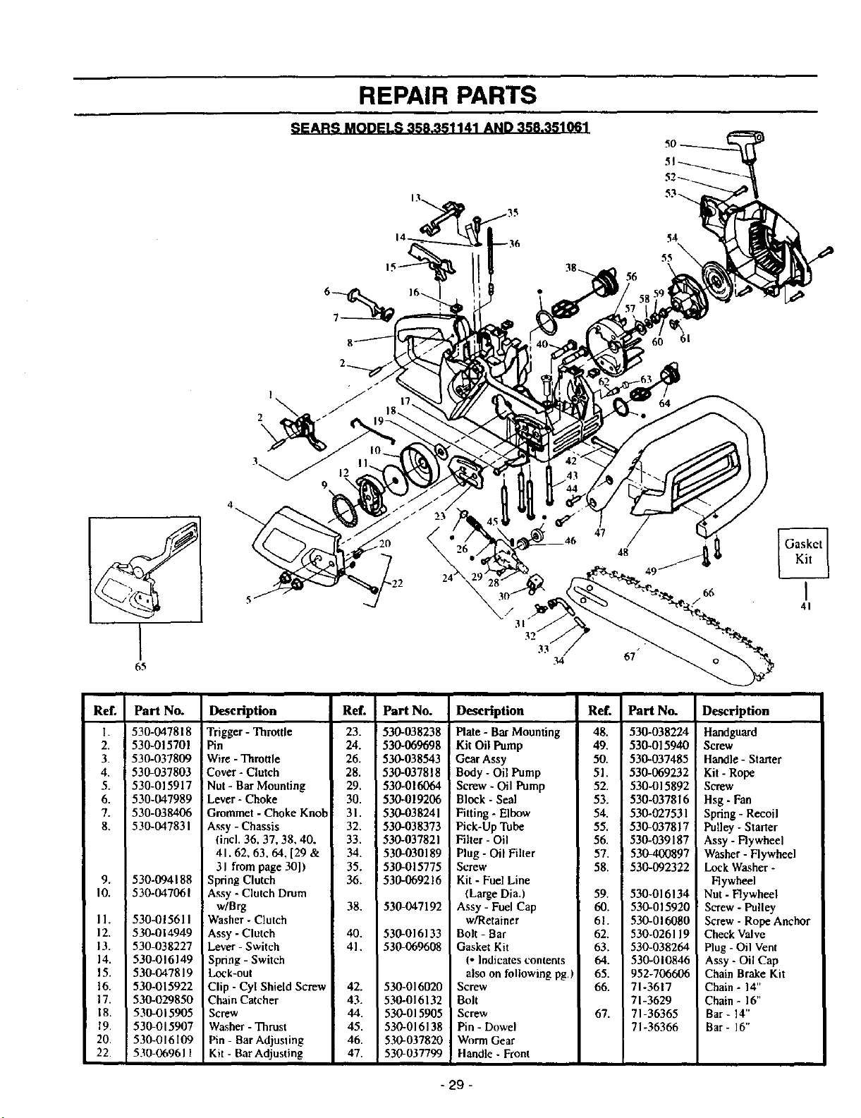
REPAIR PARTS
SEARS MODELS 358.351141 AND 358.351061
61
65
33
34
66
I
41
Ref.
L
2.
3.
4.
5.
6.
7.
8.
9.
I0.
II.
12.
13.
14.
15.
16.
17.
18.
19.
20
22.
Part No.
530-047818
530-015701
530-037809
530-037803
530-015917
530-047989
530-038406
530-047831
530-094188
] 530-047061
530-015611
530-014949
530-038227
530-016149
530-047819
530-015922
530-029850
530-015905
530-015907
530-016109
530-069611
Description
Trigger - Throttle
Pin
W_re - Throttle
Cover - Clutch
Nut - Bar Mounting
Lever - Choke
Grommet - Choke Knob
Assy - Chassis
(incl. 36, 37, 38, 40,
41.62, 63, 64, [29 &
31 from page 30])
Spring Clutch
Assy - Clutch Drum
w/Brg
Washer - Clutch
Assy - Clutch
Lever - Switch
Spring - Switch
Lock-out
Clip - Cyl Shield Screw
Chain Catcher
Screw
Washer - Thrust
Pin - Bar Adjusting
Kit- Bar Adjusting
Ref.
23.
24.
26.
28.
29.
30.
31.
32.
33.
34.
35.
36.
38.
_0.
41.
42.
43.
44.
45.
46.
47.
Part No.
530-038238
530-069698
530-038543
530-037818
530-016064
530-019206
530-038241
530-038373
530-037821
530-030189
530-015775
530-069216
530-047192
530-016133
530-069608
530-016020
530-016132
530-015905
530-016138
530-037820
530-037799
Description
Plate - Bar Mounting
Kit Oil Pump
Gear Assy
Body - Oil Pump
Screw. Oil Pump
Block - Seal
Fitting - Elbow
Pick-Up Tube
Filter - Oil
Plug - Oil Filter
Screw
Kit - Fuel Line
(Large Dia.)
Assy - Fuel Cap
w/Retainer
Bolt - Bar
Gasket Kit
(- Indicates contents
also on following pg.)
Screw
Bolt
Screw
Pin - Dowel
Worm Gear
Handle - Front
Ref.
48.
49.
50.
51.
52.
53.
54.
55.
56.
57.
58.
59.
60.
61.
62.
63.
64.
65.
66.
67.
Part No.
530-038224
530-015940
530-037485
530-069232
530-015892
530-037816
530-027531
530-037817
530-039187
5304.00897
530-092322
530-016134
530-015920
530-016080
530-026119
530-038264
530-010846
952-706606
71-3617
71-3629
71-36365
71-36366
Description
Handguard
Screw
Handle - Starter
Kit - Rope
Screw
Hsg - Fan
Spring - Recoil
Pulley - Starter
Assy - Flywheel
Washer - Flywheel
Lock Washer -
Flywheel
Nut - Flywheel
Screw - Pulley
Screw - Rope Anchor
Check Valve
Plug - Oil Vent
Assy - Oil Cap
Chain Brake Kit
Chain- 14"
Chain - 16"
Bar- 14"
Bar- 16"
- 29 -
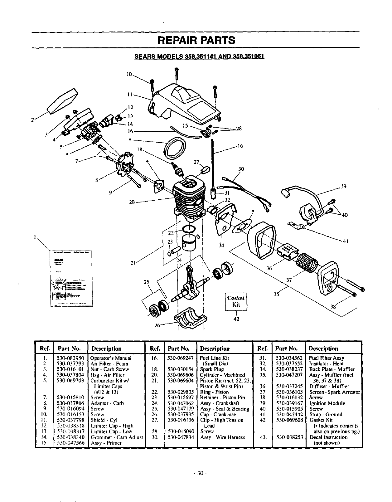
REPAIR PARTS
SEARS MODELS 358.351141 AND 358.351061
1\
16
34
30
25
42
36
35
37
Ref.
I.
2.
3.
4
5.
7.
8.
9.
I0.
II.
IZ
13.
14.
15,
Part No.
530-083950
530-037793
530-016101
530-037804
530-069703
530-015810
530-037806
530-016094
530-016153
530-037798
530-038318
530-038317
530-038340
530-047566
Description
Ref. Part No.
Operator's Manual 16. 530-069247
Air Filler - Foam
Nut - Carb Screw 18. 530-030154
Hs8 - Air Filter 20. 530-069606
Carburetor Kitw/ 21. 530-069604
Limiter Caps
(#12 & 13) 22. 530-029805
Screw 23. 530-015697
Adapter - Cacb 24. 530-047062
Screw 25. 530-047179
Screw 26. 530-037935
Shield -Cyl 27, 530-016136
Limiter Cap - High
Limitar Cap - Low 28. 530-016090
Grommet - Carb Adjust 30. 530-047834
Assy - Primer
Description Ref. Part No.
Fuel Line Kit 3 I. 530-014362
(Small Dia) 32. 530-037652
Spark Plug 34. 530-038237
Cylinder - Machined 35. 530-047207
Piston Kit (incl. 22, 23,
Piston & Wrist Pin) 36. 530-037245
Ring - Piston 3Z 530-036103
Retainer - Piston Pin 38. 530-016132
Assy - Crankshaft 39. 530-039167
Assy - Seal & Bearing 40. 530-015905
Cap - Crankcase 41. 530-047442
Clip - High Tension 42. 530-069608
Lead
! Screw
Assy - Wire Harness 43. 530-038253 =
Description
Fuel Filter Assy
Insulator - Heat
Back Plate - Muffler
Assy - Muffler (incl.
36, 37 & 38)
Diffuser - Muffler
Screen - Spark Arrestol
Screw
Ignition Module
Screw
Strap - Ground
Gasket Kit
(. Indicates contents
also on previous P8-)
Decal Instruction
(not shown)
- 30 -
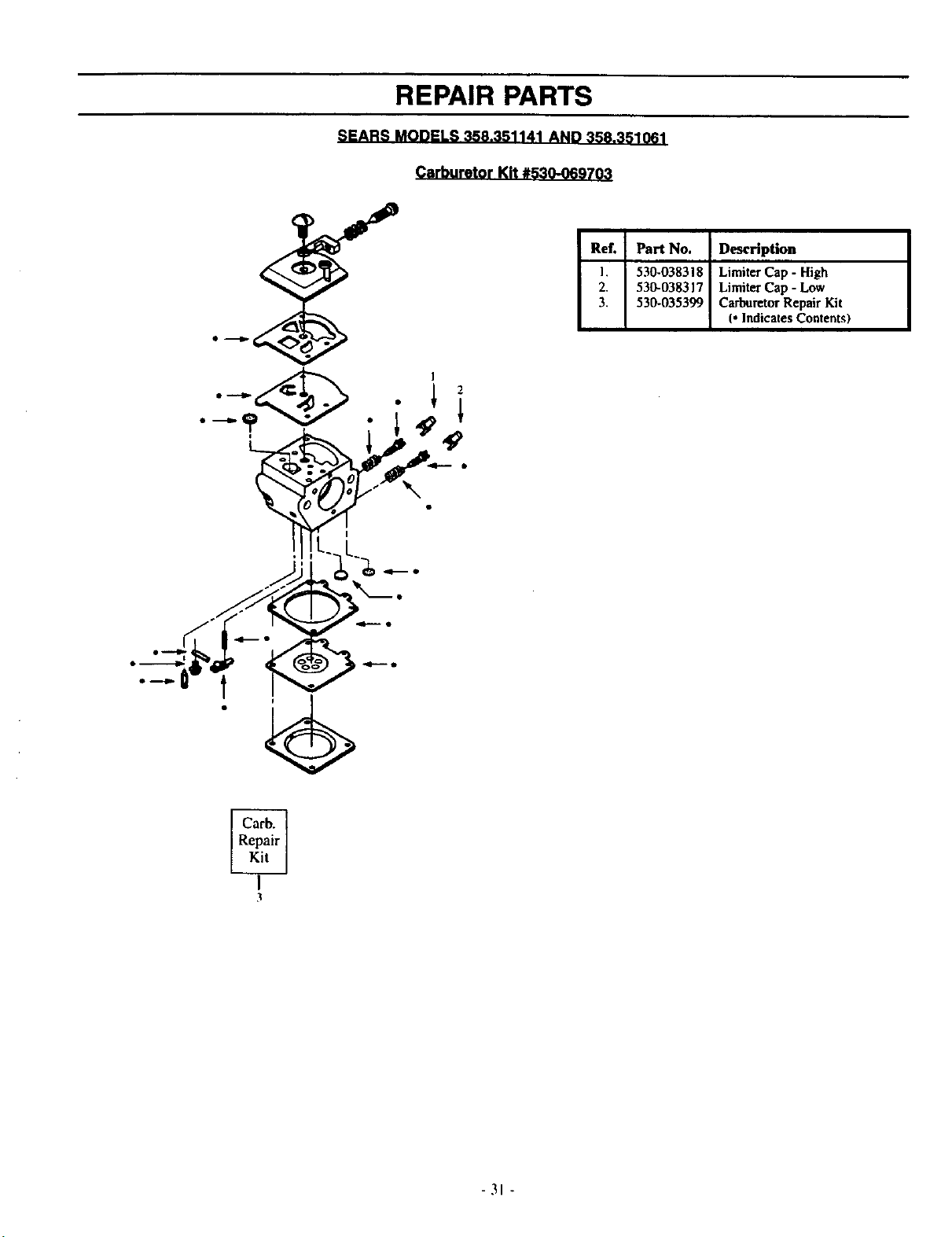
REPAIR PARTS
SEARS MODELS 358.351141 AND 358.351061
Carburetor Kit #530-069703
l 2
Ref.
I.
2.
3.
Part No. Description
530-038318 Limiter Cap - High
530-038317 Limiter Cap - Low
530-035399 CarburetorRepair Kit
(*Indicates Contents)
I
t
I
3
-31 -
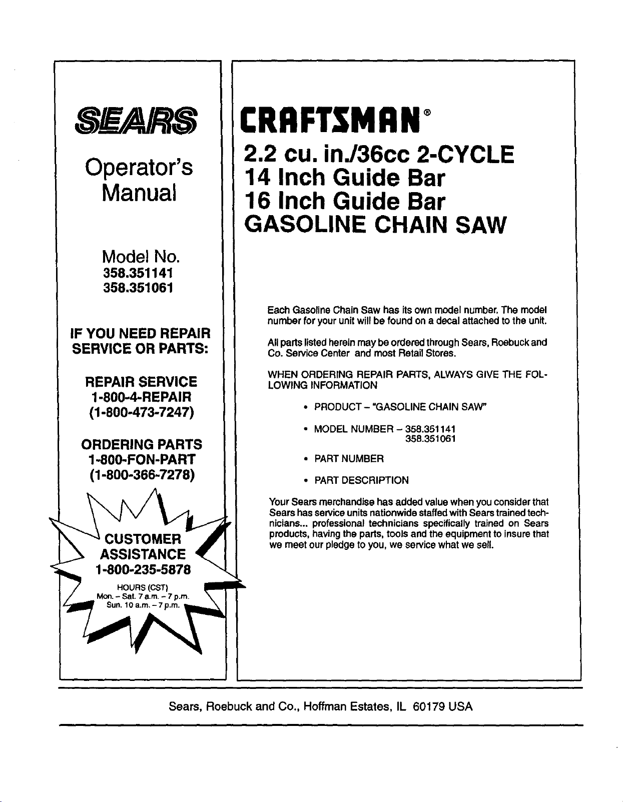
Operator's
Manual
Model No.
358.351141
358.351061
IF YOU NEED REPAIR
SERVICE OR PARTS:
REPAIR SERVICE
1-800-4-REPAIR
(1-800-473-7247)
ORDERING PARTS
1-800-FON-PART
(1-800-366-7278)
HOURS (CST)
Mort.- Sat. 7a.m.- 7 p.m.
Sun. 10 a.m.- 7p.m.,
CRRFTSMRN
2.2 cu, inJ36cc 2-CYCLE
14 Inch Guide Bar
16 Inch Guide Bar
GASOLINE CHAIN SAW
Each Gasoline Chain Saw has its own model number.The model
number for yourunitwill be found on a decal attached tothe unit.
Allparts listedherein may be orderedthrough Sears, Roebuckand
Co. Service Center and most Retail Stores.
WHEN ORDERING REPAIR PARTS, ALWAYS GIVE THE FOL-
LOWING INFORMATION
• PRODUCT- "GASOLINE CHAIN SAW"
• MODEL NUMBER - 358.351141
358.351061
• PART NUMBER
• PART DESCRIPTION
Your Sears merchandise has added value when you considerthat
Sears hasserviceunitsnationwide staffedwith Sears trained tech-
nicians.., professional technicians specifically trained on Sears
products, havingthe parts, tools and the equipment to insurethat
we meet our pledge to you, we servicewhat we sell.
Seam, Roebuck and Co., Hoffman Estates, IL 60179 USA