Loading ...
Loading ...
Loading ...
13
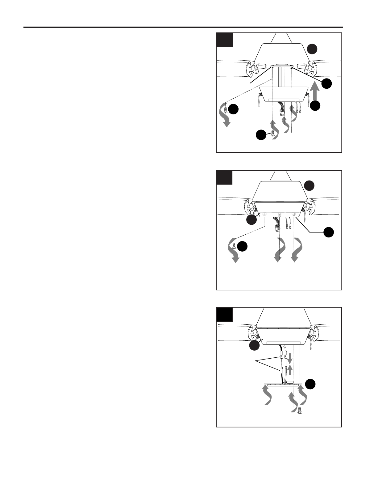
FINAL INSTALLATION
4.
Remove one motor plate screw (P) from motor
plate preassembled on the underside of the motor
housing (D) and partially loosen the other two
motor plate screws (P). Align slotted holes in
switch housing (H) with loosened motor plate
screws (P), allowing molex connections from
motor housing (D) to come through hole in switch
housing (H). Twist switch housing (H) to lock.
Re-insert the motor plate screw (P) that was
removed and securely tighten all three motor plate
screws (P).
4
I
P
I
P
I
P
H
D
Motor
Plate
5.
Remove two switch housing screws (O) from
underside of switch housing (H) and partially
loosen the other switch housing screw (O).
3
5
O
F
O
D
molex
connections
6
Connect WHITE molex wire from LED light kit (F) to
WHITE molex wire from switch housing (H).
Connect BLUE molex wire from LED light kit (F) to
BLACK (or BLUE) molex wire from switch housing
(H). Make sure molex wire connections snap
together securely.
6.
H
H
Loading ...
Loading ...
Loading ...