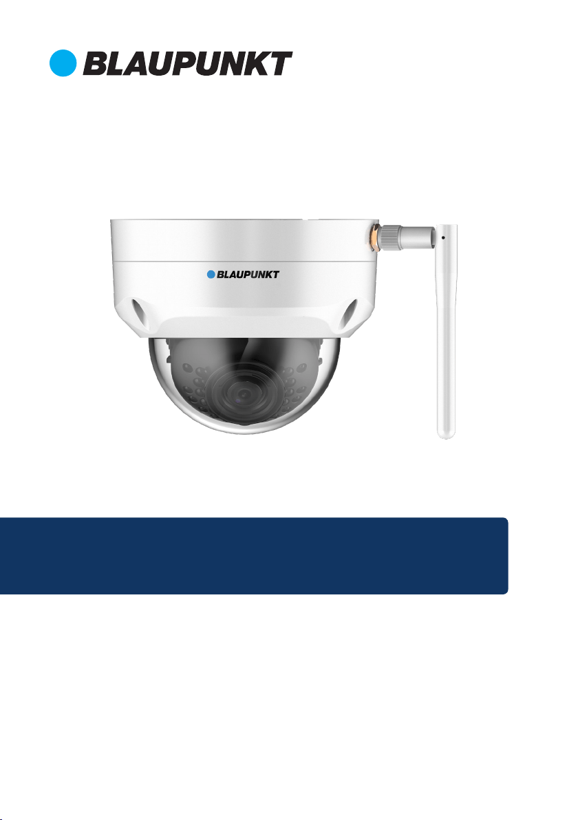
Home Security IP Camera
Enjoy it.
Quick Start Guide
IP Camera VIO-D40


EN Quick Start Guide
IP Camera VIO-D40
4
DE Schnellstart-Anleitung
IP Kamera VIO-D40
10
FR Mode d’emploi
Caméra IP VIO-D40
16
FI Käyttöopas
Sisäinen IP-kamera VIO-D40
34
ES Manual de usuario
Cámara IP para interiores VIO-D40
28
IT Manuale utente
Telecamera IP VIO-D40
22
4
English
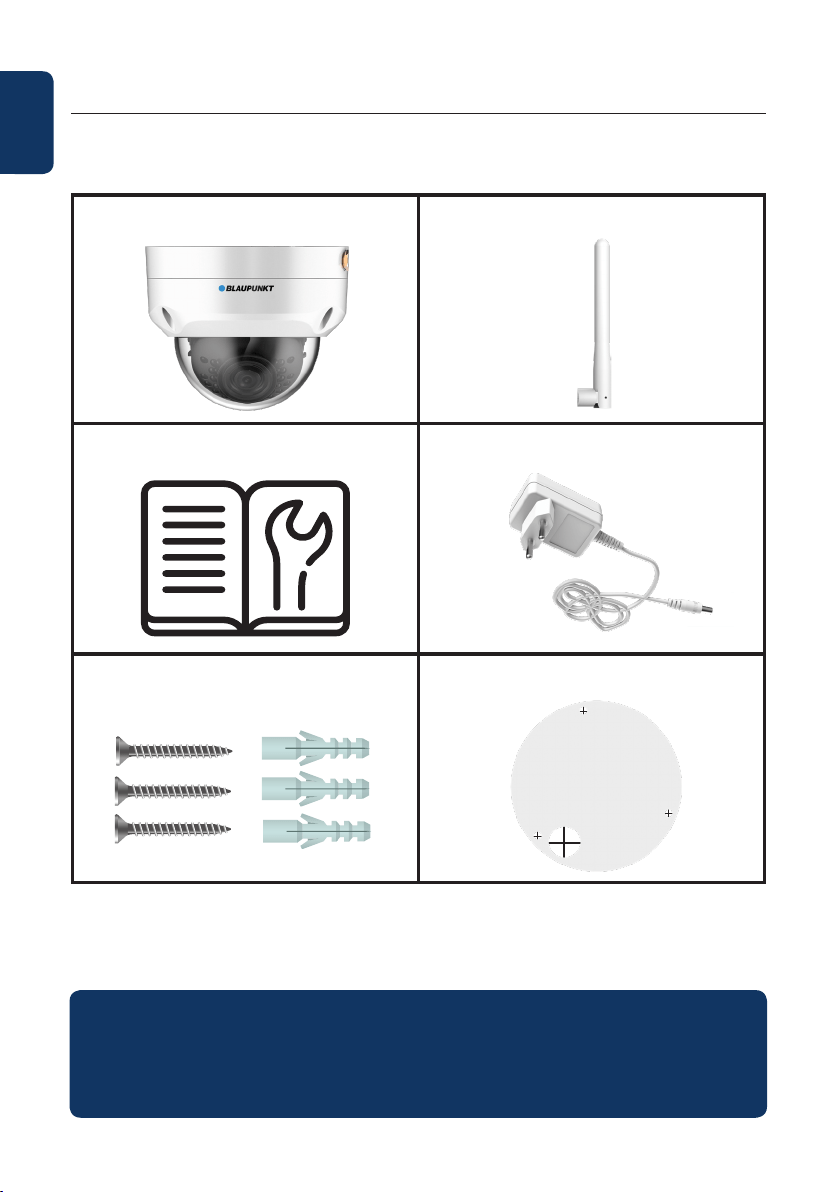
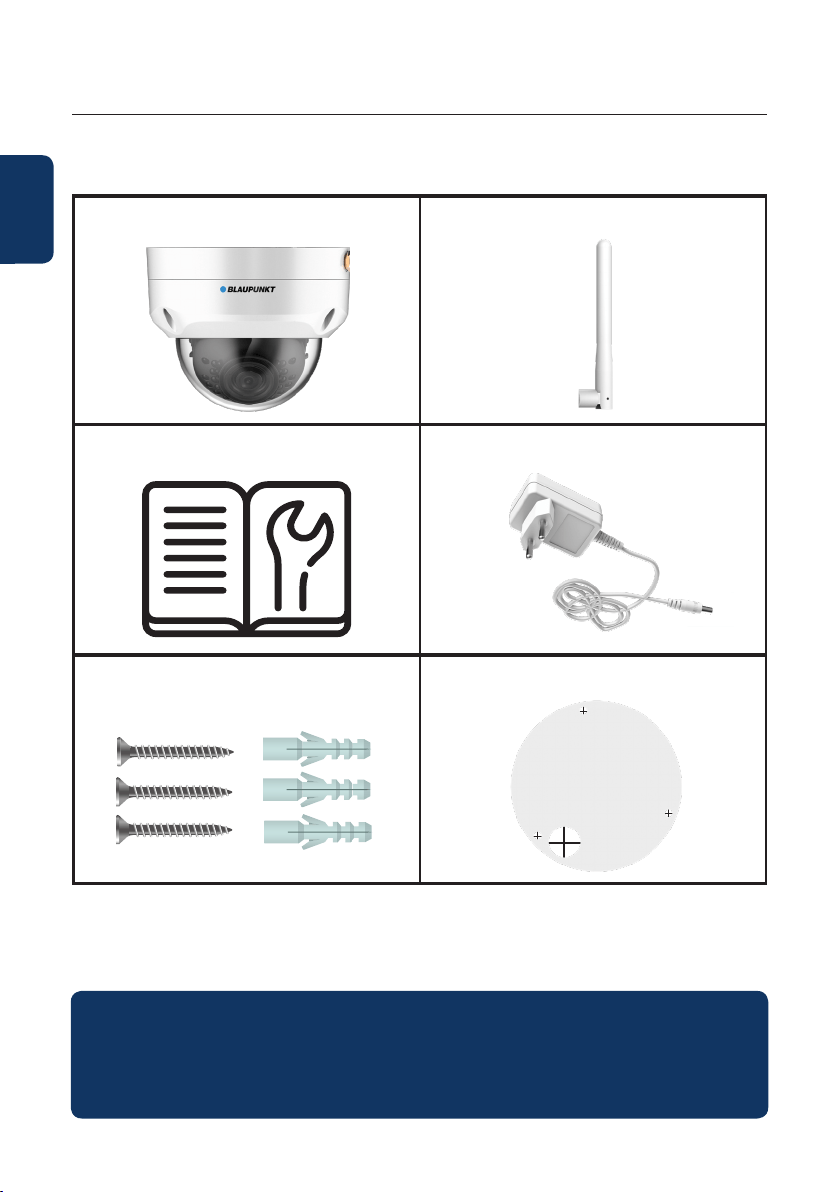
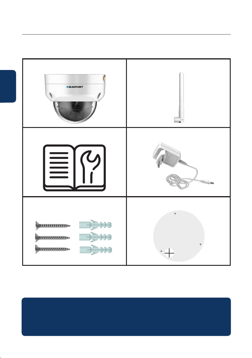
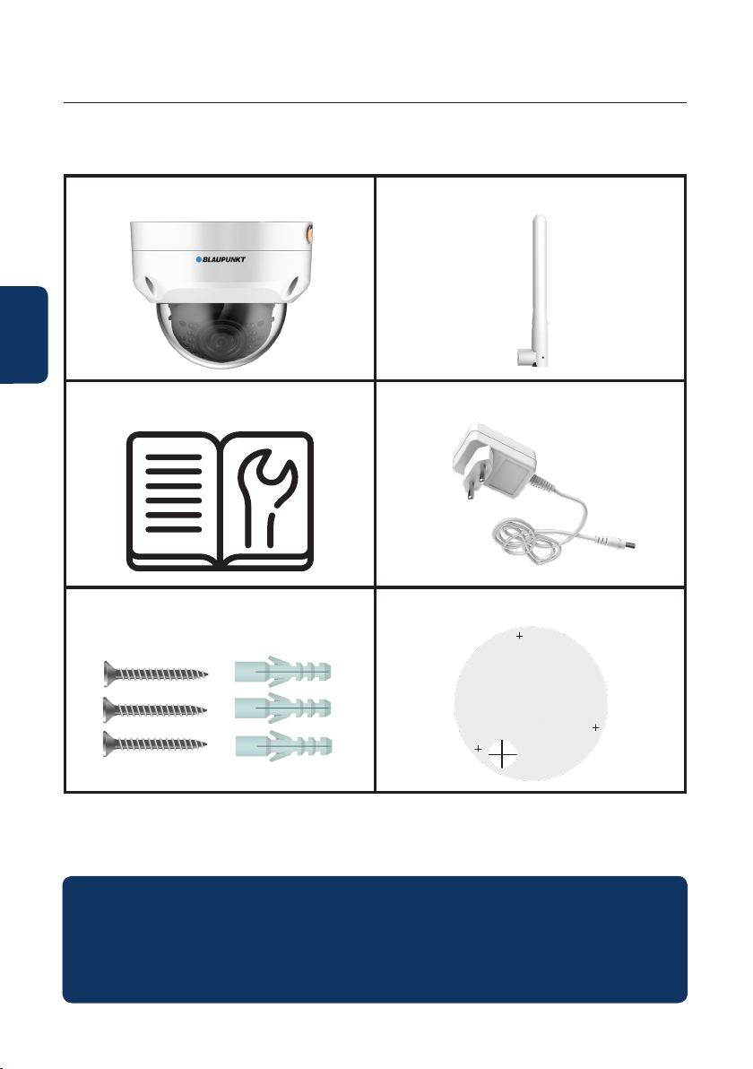
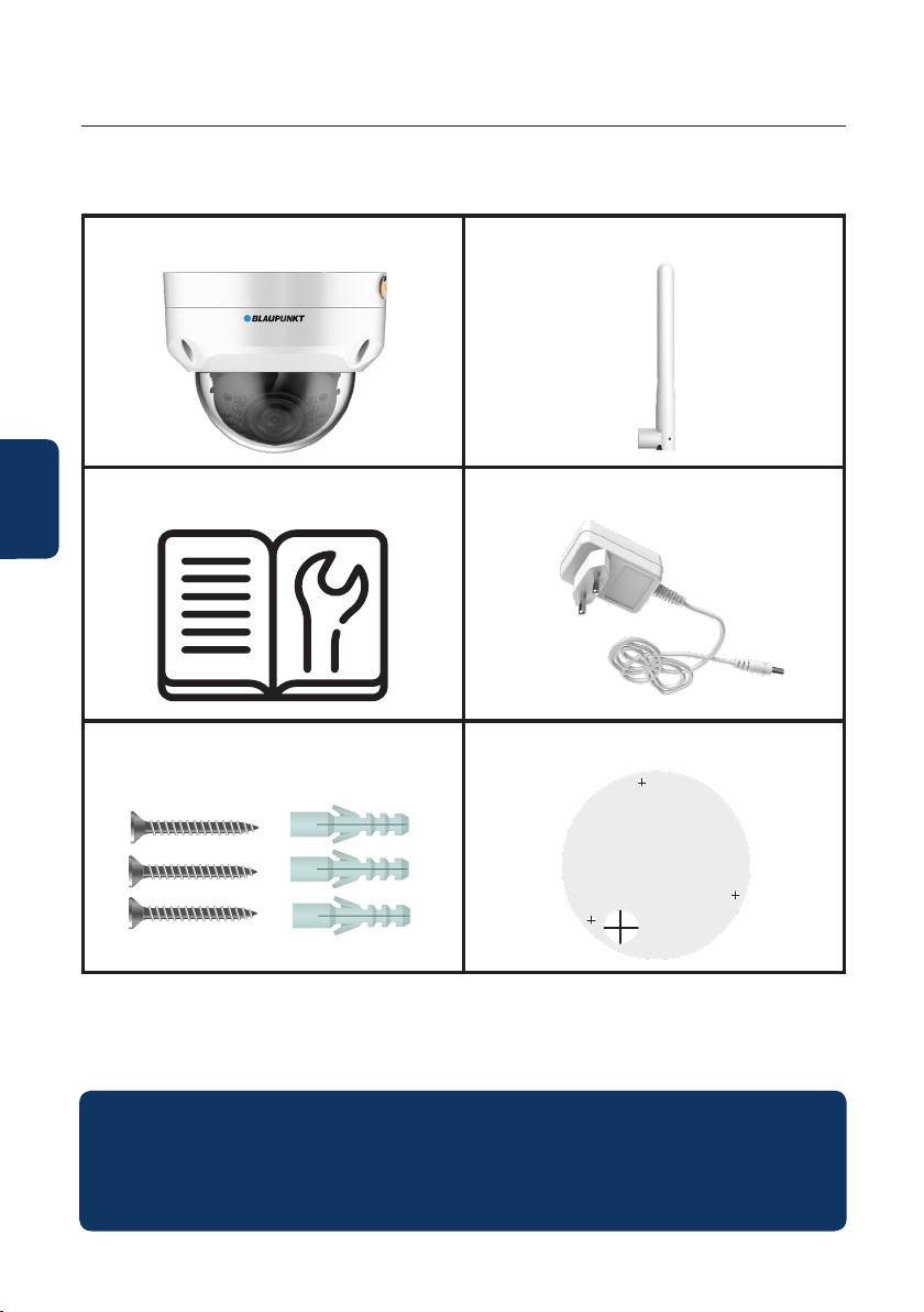
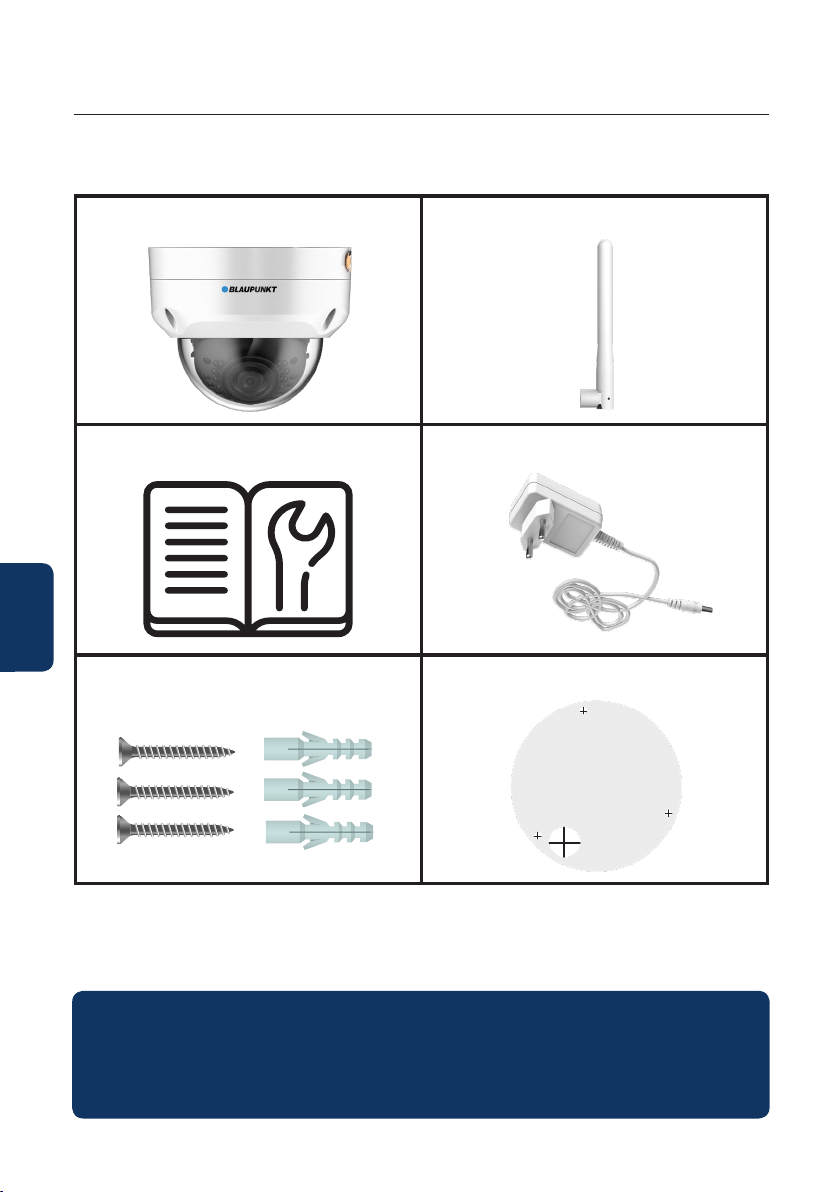
1. Kit Content
VIO-40 IP Camera
English | Manual
Antenna
Power Supply EU type
3 wall screws / 3 plastic anchors
Mounting map sticker
Quick Start Guide
NOTE:
• This manual is for reference only. Slight dierence may be found in the user
interface. All the designs and software here are subject to change without prior
written notice.
• All trademarks and registered trademarks mentioned are the properties of their
respective owners.
5
English
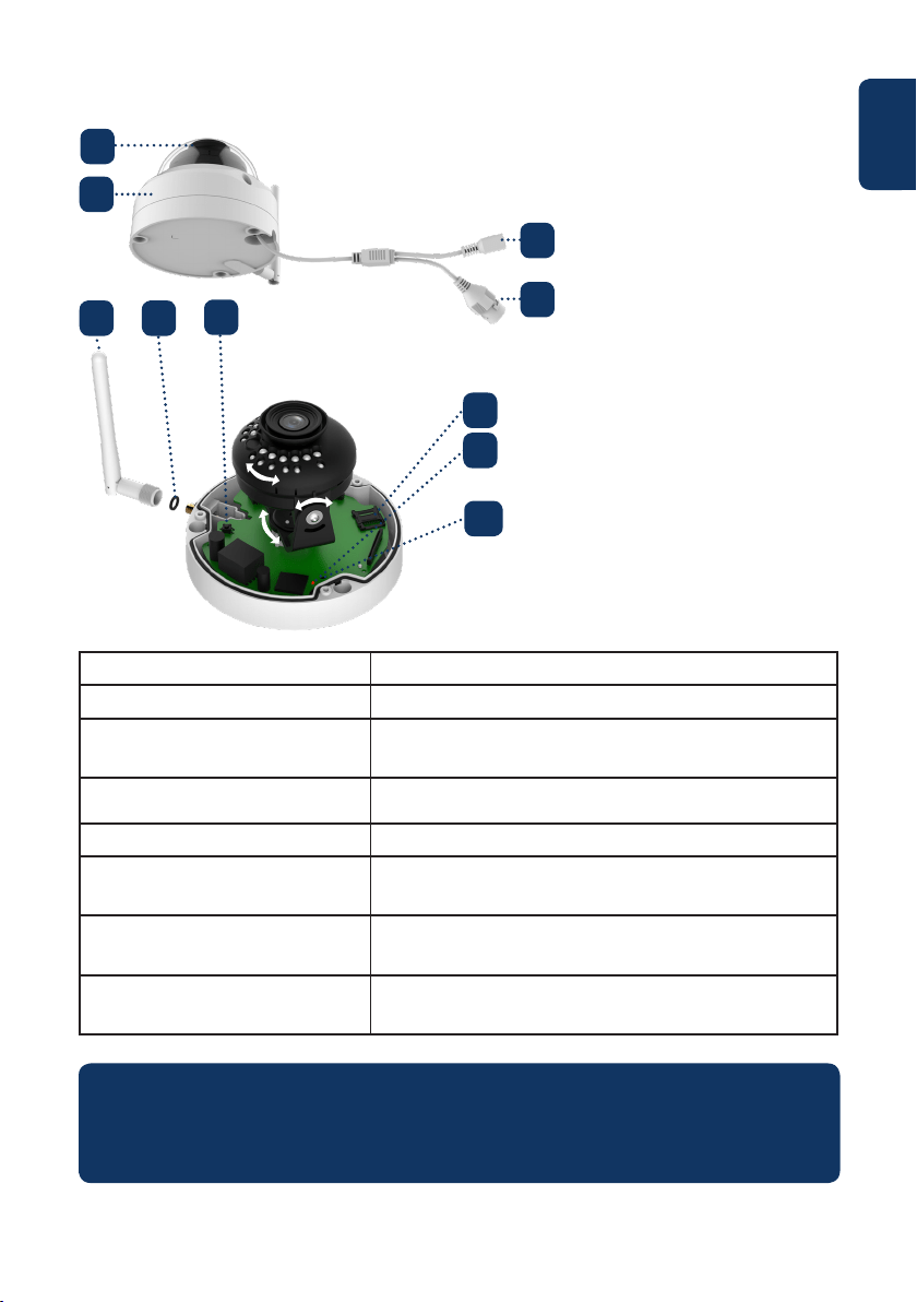
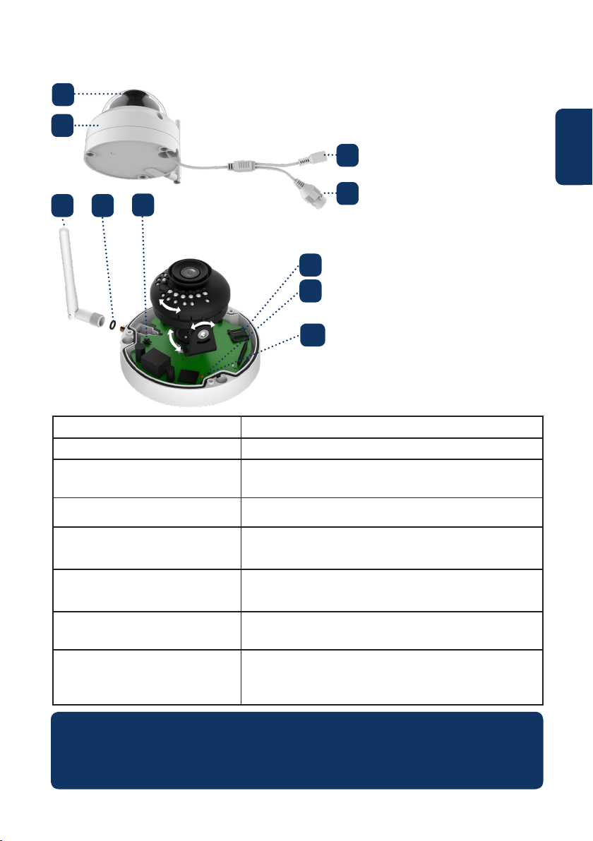
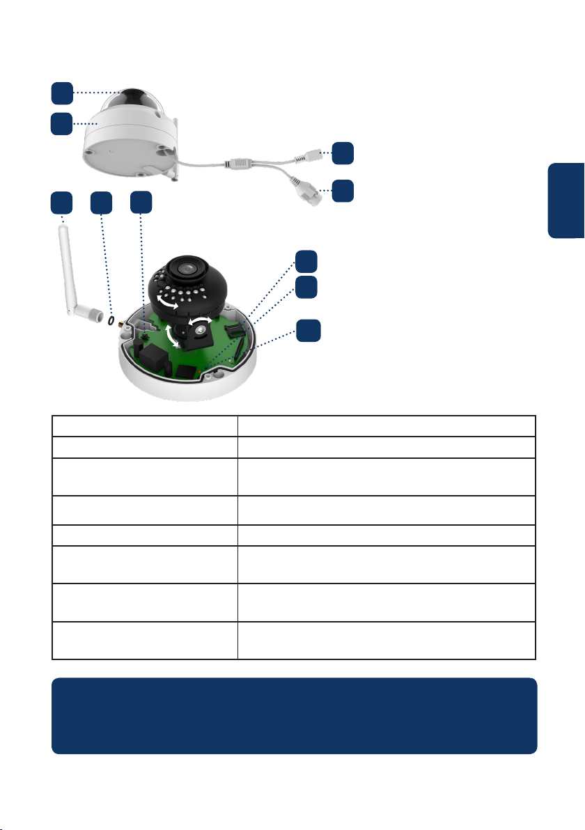
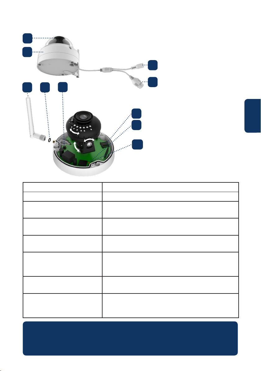
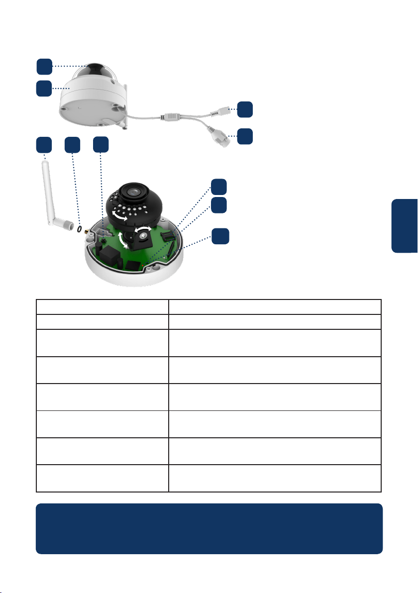
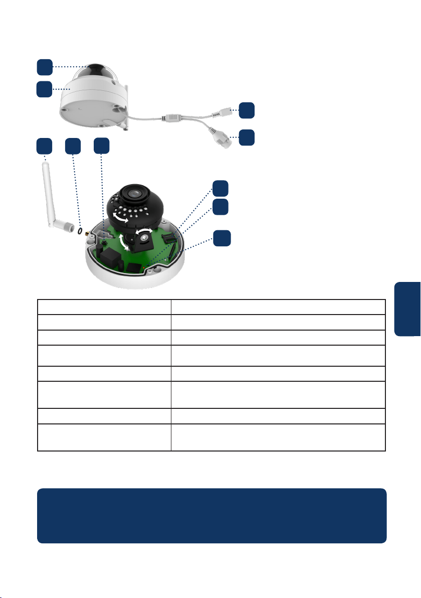
2. Product Description
1. Dome cover
2. Dome housing
3. Camera Power connector
4. Ethernet Network port
Indicator LED status: Camera status:
Red light on Camera booting up
Green light slow ashing Booting completed, waiting for WiFi
conguration
Green light quick ashing Wi smart conguration in progress.
Green light on Wi connection succeeded, operate normally.
Red and green lights ash
alternately
Camera rmware upgrade
Red light slow ashing Network connection failure or disconnected from
the network
Red light quick ashing Device malfunction, fail to boot up or SD card
malfunction. Please go to chapter 6 “Help”.
5. Wireless antenna
6. Waterproof ring
7. Reset button
8. Micro SD card slot
9. Indicator light 1
10. Indicator light 2
NOTE:
This quickstart guide explains the installation and registration of the VIO camera. If
you want to learn more about the camera or the Cam4Home Plus app please check
chapter 6.
1
2
4
3
5 6
7
8
10
9

6
English
Download and install the “Cam4Home Plus” APP to
your smartphone from the App Stores.
3. Learn in a Camera
Connect your smartphone to your Wi-Fi network.
Step 1:
Step 2:
NOTE: If you are using a dual-band router, make sure that your smartphone is
connected to a 2.4 GHz WiFi Network and not to a 5GHz Wi Network. To learn
more about this please check your router manual.
Open the “Cam4Home Plus” APP. Create a user account by pressing the
“sign up” button located at the bottom left hand side.
To add a new camera tap the “+” button at the top right of the screen and
scan the QR code of the camera (refer to chapter 2 product description). Then follow the
instructions on the App to complete the camera registration.
Step 3:
Step 4:
NOTE: If you encounter any problem during the registration, check Chapter 5
Camera settings:
To access the camera settings go to the camera dasboard and tap the settings icon
at the top right.
4. Cam4Home Plus Management
Camera dashboard:
Tap on your camera under the main “device” menu. This will bring you to the camera
dashboard, where you can see the camera live stream video.
Push notications
On the device menu tap the 3 dot icon and select “Alarm Notications” .
Tap the “Alarm Notication” button to activate / deactivate the push notications.
NOTE: To receive push notications “Motion detection” must be enabled.
Important: Ensure that you have given permission to show pop up notications on your
smartphone permission settings.
Motion detection
To enable / disable motion detection go to: Camera dashboard --> Settings icon --> Arm
settings --> Motion detection. Note: Motion detection is enabled by default.
Video Storage
To storage video recordings the camera needs to have a Micro-SD card installed (see
chapter 5.1) or a Cloud Storage Plan activated.
7
English
5. Installation
• Check your WiFi signal strength and make sure that the WiFi signal is strong at
the location of your camera. For best performance, the smartphone needs to be
connected to a Wi-Fi network.
• Note: We recommend taking a picture of the label at the back of the camera. In case you
need to check the serial number, MAC address or QR-Code at a later stage.
Step 1:
5.1. Micro SD installation (optional)
• Locate the Micro SD-Card compartment of the D40. (refer to chapter 2 point )
• Slide the Micro-SD card slot to the OPEN position as displayed on the Micro-SD
card slot. After the Micro-SD card slot is in the open position open it and place the
Micro-SD card inside. Close the Micro-SD card slot and move it to the LOCK position
as displayed on the Micro-SD card slot.
8
NOTE: The Micro SD-Card is mandatory for local recording. Please make sure the
Micro SD-Card is CLASS10 rated. Supported are Micro SD-Cards from 8GB to 256GB .
Use the included hex wrench to open the dome cover by unfastening three
inner hex screws. (see below picture).
Take out the mounting map sticker and stick it on the ceiling or the wall.
Step 2:
Step 3:
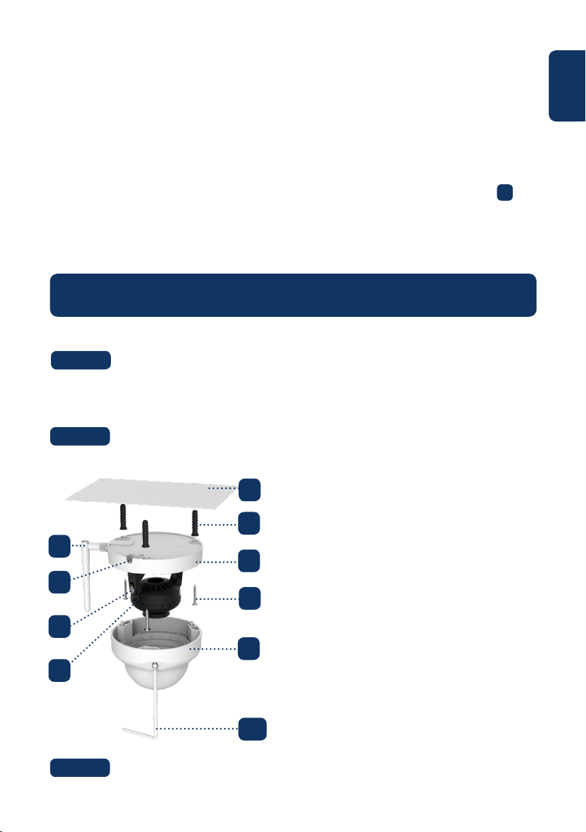
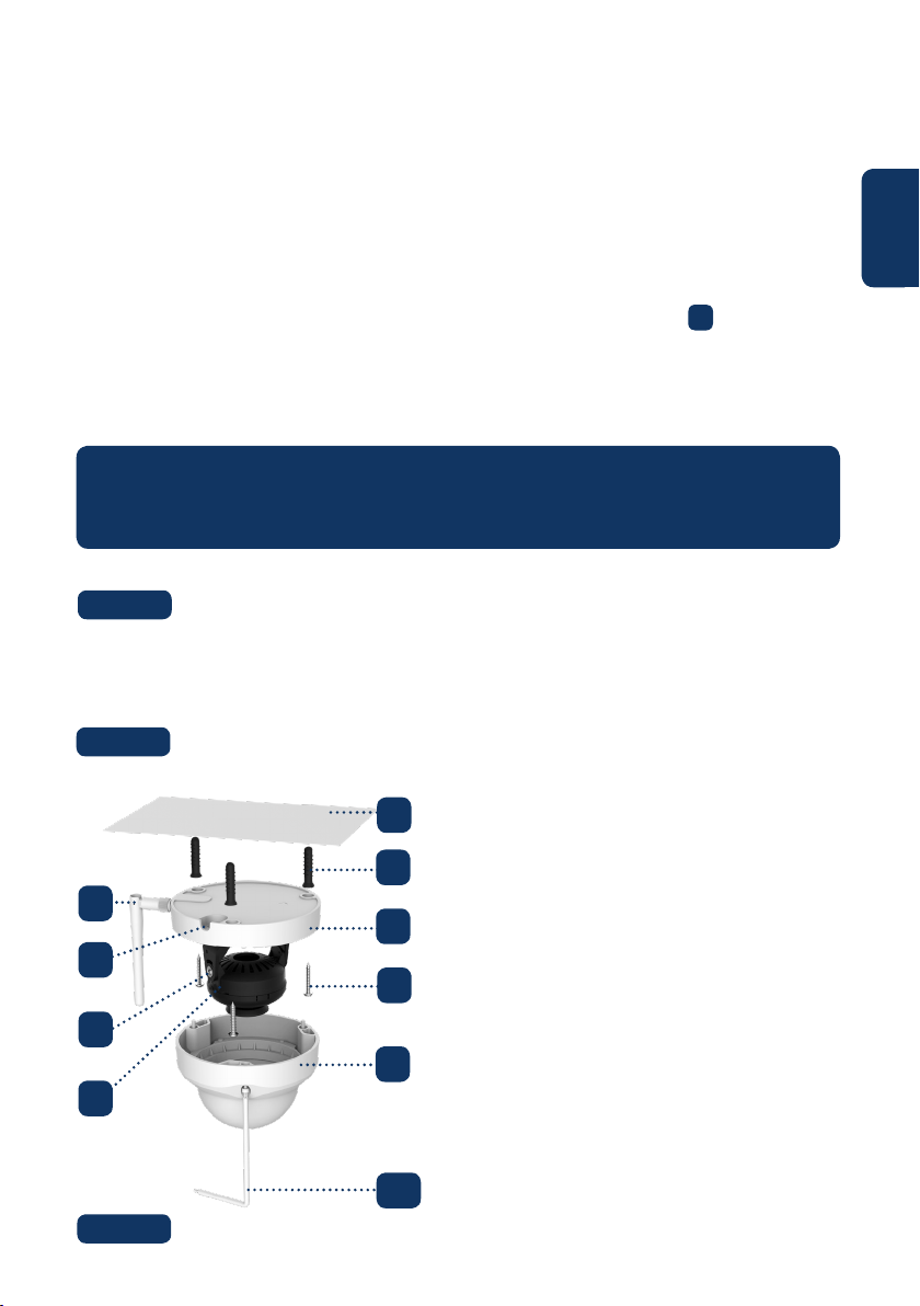
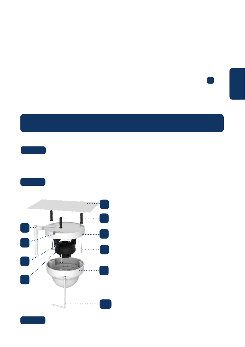
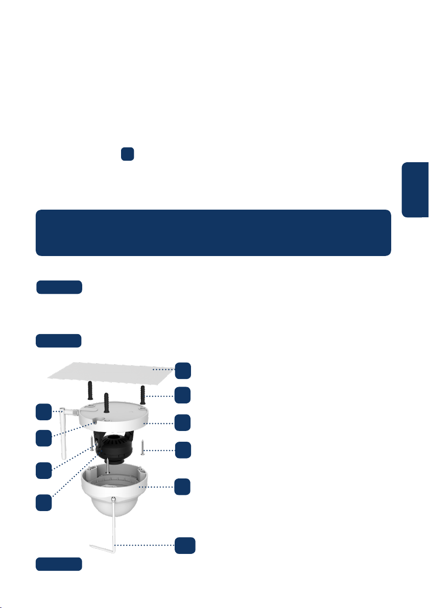
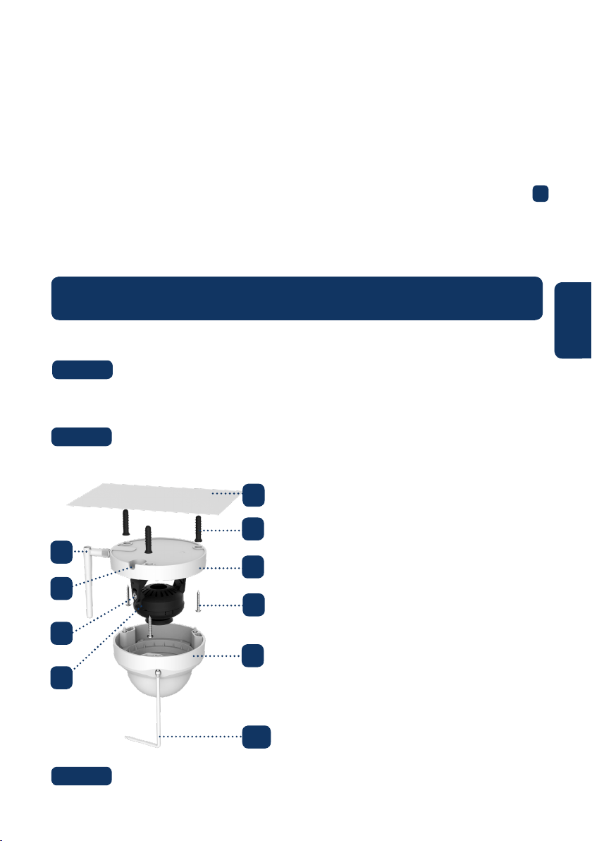
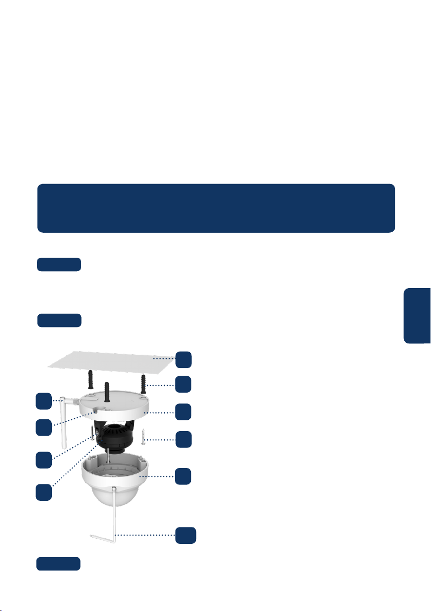
5.2. Installation without mounting bracket
Find the desired installation location for the camera. Position the camera
where a power socket is in sucient proximity. Turn the camera ON and use the live
view image from the app to position the camera where everything to monitor is well in
view.
1. Antenna
2. U-shaped side exit
3. Rotational Bracket
4. LED Ring
5. Ceiling or Wall
6. Plastick Anchor
7. Dome Pedestal
8. Installation Screw
9. Dome Cover
10. Inner Hex Wrench
10
4
5
6
7
8
9
3
2
1

8
English
Drill through the 3 small marked points and install the plastic anchors on
the 3 small holes. Then choose one of the option bellow:
Step 5:
Adjust the dome camera according to the mounting map sticker and line
up the three screw holes in the dome pedestal to the three plastic anchors holes. Fix the
three screws in the three plastic anchors rmly.
Step 6:
Adjust the dome camera lens by moving the camera rotation bracket, and
check the position of the camera with the live image of the camera on your mobile
device. The camera rotation bracket can be moved manually by 355 degrees left to right
and 64 degrees up or down. To prevent that the LEDs on the LED ring get blocked by
the metal housing of the dome camera it is important to rotate the LED ring horizontal-
ly by 355 degrees and adjust the lens image to the desired position.
Note: When it rotates to 64° vertically, please pay attention to the image rotation direction to
avoid the outer cover blocking IR light and inuencing IR eect.
Step 7:
Use three Inner hex wrench screws to x the Dome housing on the pedestal.
Step 8:
5.3. Installation with mounting bracket (optional)
• The VIO-DMB1 mounting bracket is an optional accessory purchased separately from
the camera. If you desire to install the camera with the mounting bracket please refer
to the manual inside the mounting bracket box.
Connect the Camera Power connector to the included power supply cable.
Then connect the power supply cable to the power line socket. Optional: If you want
to install your camera via Ethernet cable, connect your camera to the router using an
Ethernet cable.
Step 9:
• If the ethernet network port and camera power connector need to exit from the back
of the camera through the installation surface, drill a hole according to the size of the
bigger hole on the mounting map sticker. (For the big hole ideally use a SDS-max
20mm drill)
• If the Ethernet Network port and Camera Power connector need to exit from the side
of the camera, the cable must go through the U-shape side exit on dome pedestal.
Use the mounting map sticker, to mark the position of the drilling points.
There are three holes for the screws and a big hole for the ethernet network port and
the camera power connector.
Step 4:
NOTE:
If due to special circumstances, such as a reinforced concrete wall, it’s not possible
to drill a hole of 20mm diameter, you have the option to cut o the thick Ethernet
Network port - see “Chapter 2. Product Appearance”, and seal it with a proper sealing
tape. With this option only a 12mm diameter drill is needed.
Alert: If you decide to cut o the Ethernet Port, you will lose the possibility to connect
the camera by Ethernet cable to a router or NVR. Additionally, you lose your right of
return.
9
English
6.5 Factory Reset
Plug in the camera and wait 1 minute until it boots up.
Step 1:
6. Help
If you experience any issue or have questions go to the FAQ in the app at:
“Me” menu -> Settings --> FAQ
For additional help, contact our technical support. To nd
your country customer support service, visit:
http://security.blaupunkt-service.com
6.1 FAQ
6.2 Cam4Home Plus Manual
6.3 How to Videos
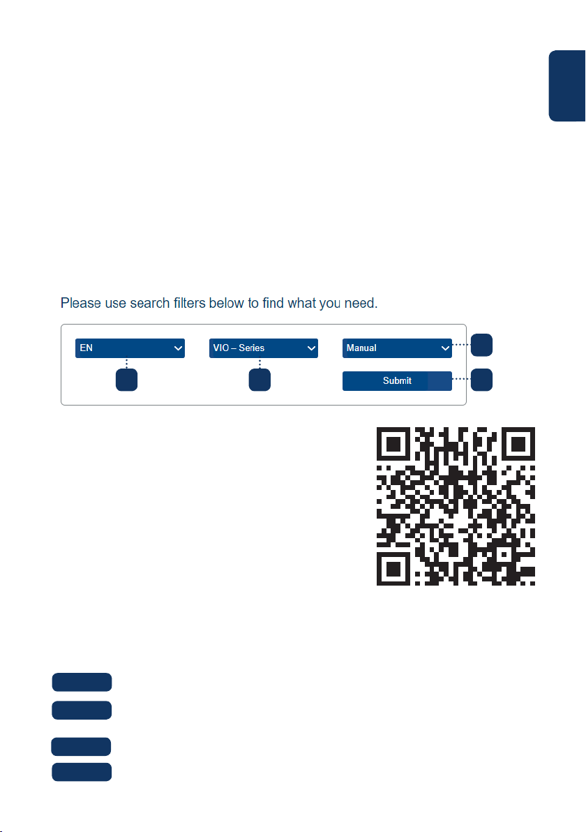
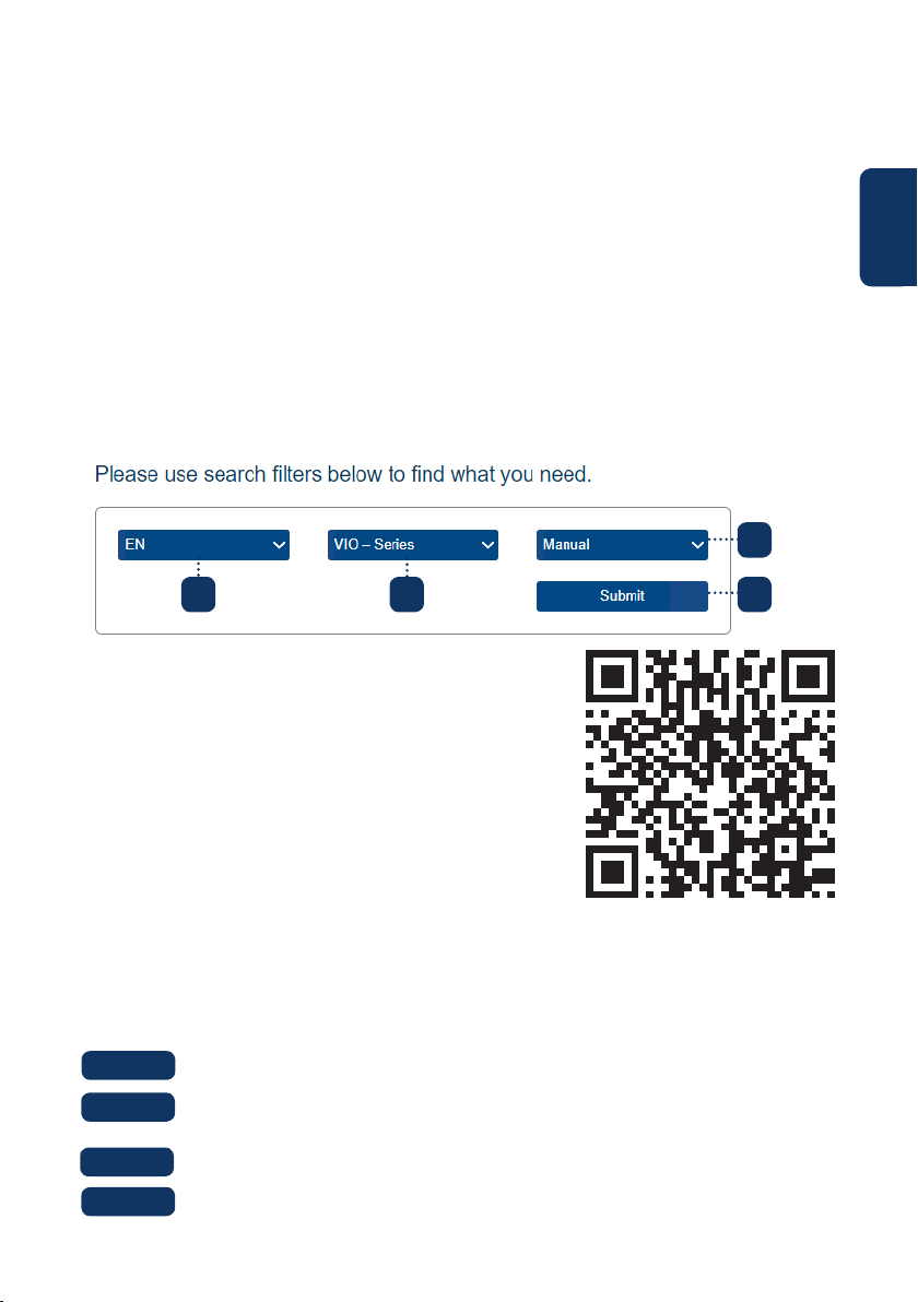
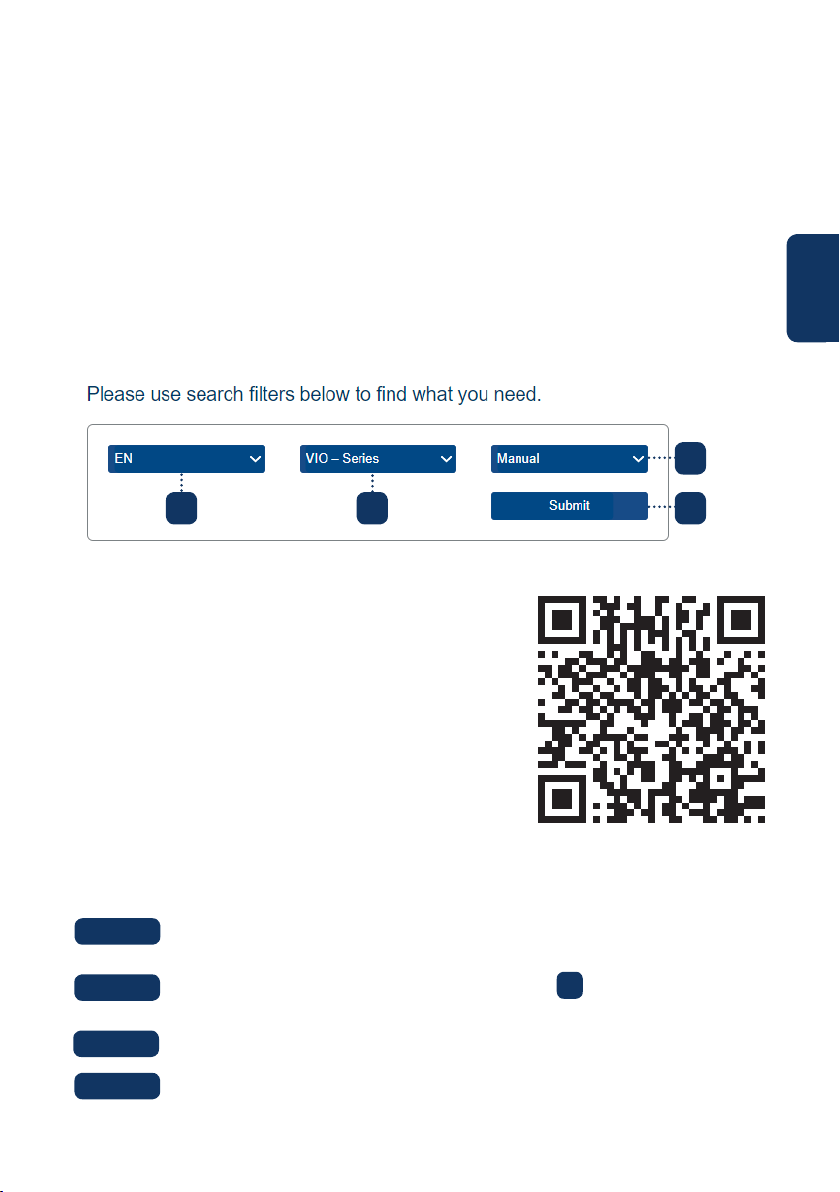
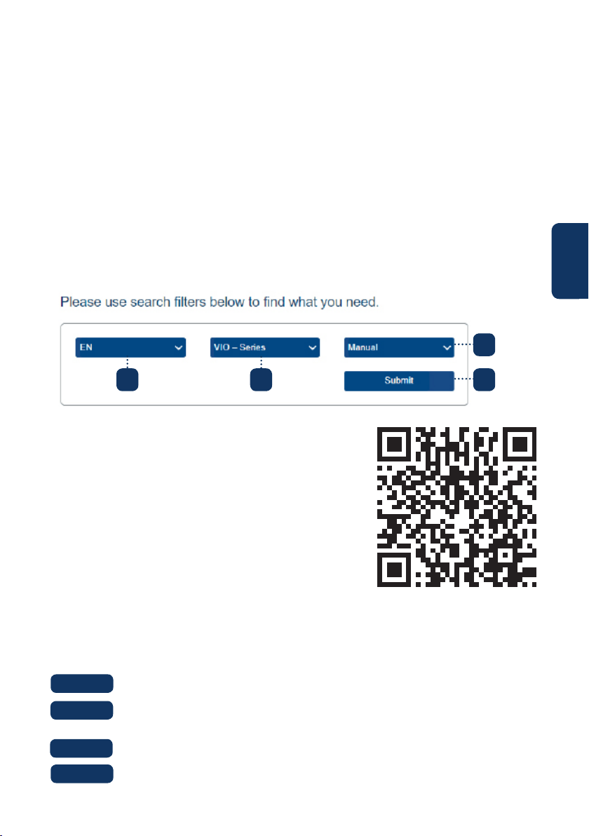
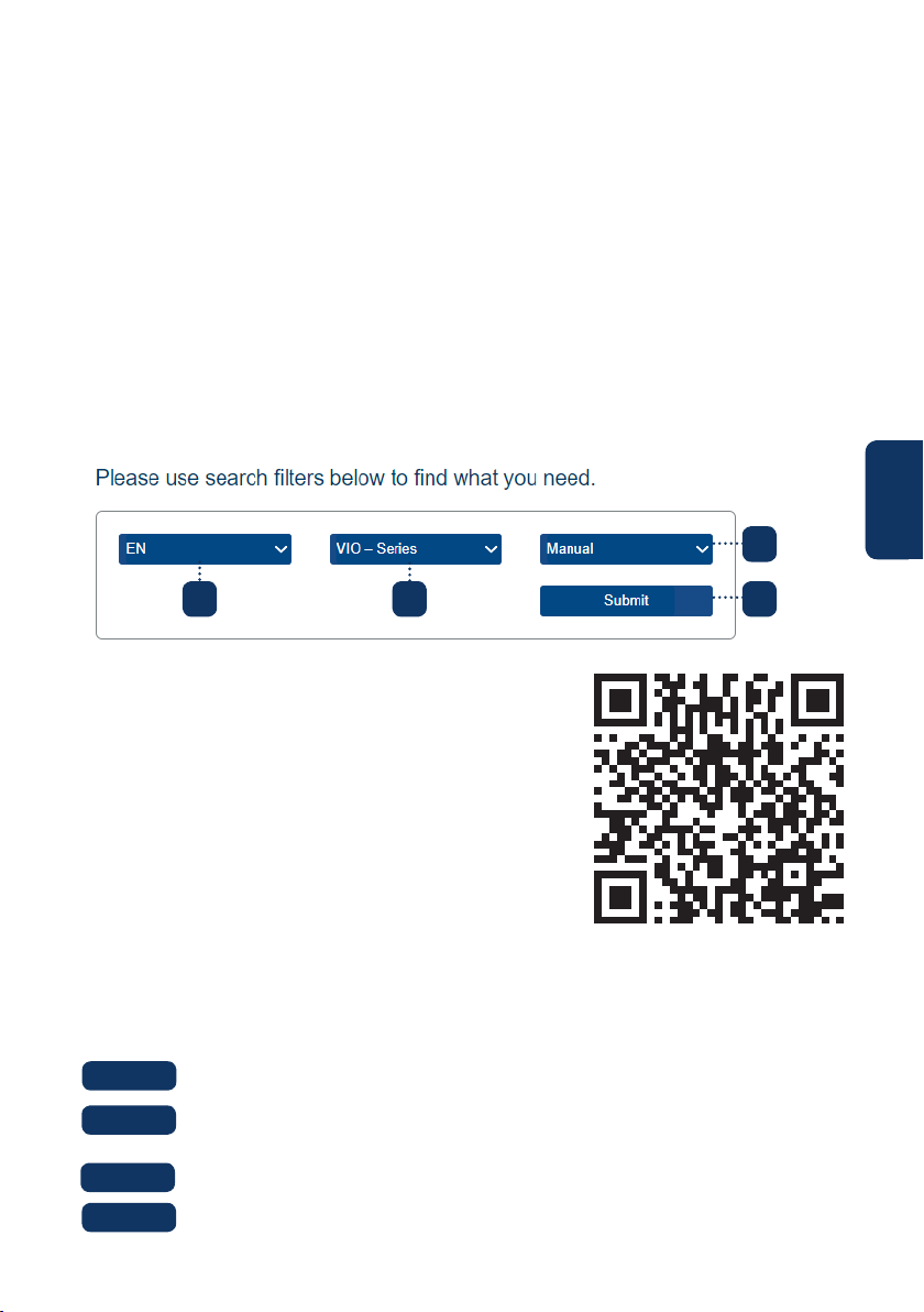
If you want to learn more details of the Cam4Home Plus APP, download the Main APP
manual, with the following steps:
Visit: https://www.blaupunkt.com/service
1. On the 1st dropdown menu select your language
2. On the 2nd dropdown menu select “VIO-Series”
3. On the 3rd dropdown menu select “Manual”
4. Click “Submit”
5. Locate and click on “VIO-- Cam4Home Plus - Manual”
6.4 Customer Support and Returns
For “How-to-Videos” on the installation and registra-
tion please visit our youtube channel by scanning
the QR code. And then select your language from the
playlist.
Press the reset button (refer to chapter 2) for 15 seconds until the red Indi-
cator light turns on and starts ashing.
Wait until the green indicator light ashes slowly.
Now the camera is reverted to default settings.
Step 2:
Step 3:
Step 4:
1 2
3
4
Returns: If you wish to return your camera, we strongly advise that you rst delete
any camera paired to your account before sending the camera back.
10
Deutsch
1. Lieferumfang
VIO-D40 IP Kamera
Deutsch | Schnellstart-Anleitung
Antenne
Netzteil EU-Typ
3 Wandschrauben /
3 Kunststodübel
Montage-Schablone
Schnellstart-Anleitung
HINWEIS:
• Diese Schnellstart-Anleitung ist nur eine Ansatz. Es kann Abweichungen im
Vergleich zur tatsächlichen Benutzeroberäche geben. Alle Designs und die
Software können ohne Vorankündigung jederzeit geändert werden.
• Alle vorkommenden Markenzeichen und registrierten Marken sind Eigentum der
entsprechenden Eigentümer.
11
Deutsch
2. Geräteübersicht
1. Schutzabdeckung
2. Gehäuse
3. Kamera Stromanschluss
4. Ethernet-Netzwerkanschluss
LED-Statusanzeige: Kamerastatus:
Rote LED an Kamera wird hochgefahren
Grüne LED blinkt langsam Startvorgang abgeschlossen, Warten auf WLAN-
Konguration
Grüne LED blinkt schnell Smarte-WLAN-Konguration wird durchgeführt
Grüne LED an WLAN-Verbindung erfolgreich, normale
Funktionsweise.
Rote und grüne LED blinken
abwechselnd
Firmware-Aktualisierung der Kamera
Rote LED blinkt langsam Netzwerkverbindungsfehler oder Verbindung
zum Netzwerk getrennt
Rote LED blinkt schnell Gerätestörung, Startvorgang fehlgeschlagen
oder Fehlfunktion der SD-Karte. Bitte fahren Sie
mit Kapitel 6 „Hilfe“ fort.
5. WLAN Antenne
6. Wasserdichter Ring
7. Reset-Taste
8. Micro SD-Kartenfach
9. Status LED 1
10. Status LED 2
HINWEIS:
Diese Schnellstart-Anleitung erklärt die Installation und Registrierung der VIO-
Kamera. Wenn Sie mehr über die Kamera oder die Cam4Home Plus-App erfahren
möchten, lesen Sie bitte Kapitel 6.
1
2
4
3
5 6
7
8
10
9
12
Deutsch
Laden Sie die „Cam4Home Plus“ App aus dem App
Store auf Ihr Smartphone herunter und installieren Sie diese.
3. Einlernen der Kamera
Verbinden Sie Ihr Smartphone mit Ihrem WLAN Netzwerk.
Schritt 1:
Schritt 2:
HINWEIS: Wenn Sie einen Dualband-Router verwenden, stellen Sie sicher, dass
Ihr Smartphone mit einem 2,4-GHz-WLAN-Netzwerk und nicht mit einem 5-GHz-
WLAN-Netzwerk verbunden ist. Um mehr darüber zu erfahren, lesen Sie bitte die
Anleitung Ihres Routers.
Önen Sie die „Cam4Home Plus“ App. Erstellen Sie ein Benutzerkonto,
indem Sie auf die Schaltäche “Registrieren” unten links klicken.
Um eine neue Kamera hinzuzufügen, tippen Sie auf die Schaltäche „+“
oben rechts auf dem Bildschirm und scannen Sie den QR-Code der Kamera (siehe
Kapitel 2 Produktbeschreibung). Folgen Sie dann den Anweisungen in der App, um die
Kamera-Registrierung abzuschließen.
Schritt 3:
Schritt 4:
HINWEIS: Wenn Sie während der Registrierung auf ein Problem stoßen,
lesen Sie Kapitel 5.
Kameraeinstellungen:
Um auf die Kameraeinstellungen zuzugreifen, gehen Sie zur Kamera-Übersicht
und tippen Sie auf das Einstellungssymbol oben rechts.
4. Cam4Home Plus App Funktionen
Kamera-Übersicht:
Wählen Sie nach dem Setup Ihre Kamera im “Geräte Menü” aus. Sie gelangen nun zur
Übersicht der Kamera, hier sehen Sie das Live-Stream-Video der Kamera.
Push-Benachrichtigungen:
Tippen Sie im “Geräte Menü” auf das Symbol und wählen Sie “Alarm-
benachrichtigungen” . Tippen Sie dann auf die Schaltäche “Alarm-
benachrichtigung”, um die Push-Benachrichtigungen zu aktivieren / deaktivieren.
HINWEIS: Um Push-Benachrichtigungen zu erhalten, muss “Bewegungserken-
nung” aktiviert sein.
Wichtig: Stellen Sie sicher, dass Sie der App die Berechtigung erteilen, Push-
Benachrichtigungen auf dem Startbildschirm anzuzeigen.
Bewegungserkennung:
Um die Bewegungserkennung zu aktivieren / gehen Sie zu: Kamera-Übersicht
-> Einstellungssymbol -> Bewegungserkennungs Einstellungen ->
Bewegungserkennung. Hinweis: Die Bewegungserkennung ist standardmäßig aktiviert.
Videospeicher:
Zum Speichern von Videoaufnahmen muss auf der Kamera eine Micro-SD-Karte (siehe
Kapitel 5.1) installiert oder ein Cloud-Speicherplan aktiviert sein.
13
Deutsch
Wählen Sie den gewünschten Installationsort für die Kamera aus. Position-
ieren Sie die Kamera so, dass sie den gewünschten Bereich überwachen kann. Bitte
denken Sie daran, dass sein Stromanschluss in Reichweite des Kabels vorhanden sein
muss. Überprüfen Sie die Signalstärke des WLAN-Netzes, am Installationsort und
überprüfen Sie den Bildausschnitt in der „Live Überwachung“.
5. Installation
• Überprüfen Sie die Stärke Ihres WLAN-Signals und stellen Sie sicher, dass das WLAN
Signal am Standort Ihrer Kamera stark genug ist. Für eine optimale Bildübertragung
muss das Smartphone mit einem WLAN-Netzwerk verbunden sein.
• Hinweis: Wir empfehlen, das Etikett auf der Rückseite der Kamera zu fotograeren. Falls
Sie zu einem späteren Zeitpunkt die Seriennummer, MAC-Adresse oder den QR-Code
überprüfen müssen.
Schritt 1:
5.1. Installation der Micro-SD-Karte (optional)
• Suchen Sie das Micro SD-Kartenfach der D40. (siehe Kapitel 2 Punkt )
• Um eine SD-Karte einzusetzen (nicht mitgeliefert) ist es erforderlich, den Kartenhalter
zunächst in die “OPEN” Position zu schieben wie auf dem Micro-SD-Halter abgebildet.
Nach dem Einsetzen der Karte diesen wieder in die “LOCK” Position schieben. Jetzt ist
die Micro-SD-Karte installiert und kann verwendet werden.
8
HINWEIS: Die Micro-SD-Karte ist für die lokale Aufzeichnung von Videoereignissen-
notwendig.Vergewissern Sie sich, dass die Micro SD-Karte CLASS10-zertiziert ist.
Unterstützt werden Micro-SD-Karten von 8 GB bis 256 GB.
Verwenden Sie den mitgelieferten Inbusschlüssel, um das Dome-Gehäuse
zu önen, indem Sie die drei Innensechskantschrauben lösen. (siehe Bild unten).
Schritt 2:
5.2. Montage ohne Wandhalterung (VIO-DMB1)
1. Antenne
2. Aussparung für Kabel
3. Drehhalterung
4. LED-Ring
5. Decke oder Wand
6. Kunststodübel
7. Kamerafuß
8. Schrauben
9. Dome-Gehäuse
10. Inbusschlüssel
Nehmen Sie die Montage-Schablone heraus und kleben Sie diese an die
Decke oder an die Wand.
Schritt 3:
10
4
5
6
7
8
9
3
2
1

14
Deutsch
Bohren Sie durch die 3 kleinen markierten Punkte und bringen Sie die Kunst-
stodübel an den 3 kleinen Löchern an. Wählen Sie dann eine der folgenden Optionen:
Schritt 5:
Richten Sie die Domekamera gemäß der Montage-Schablone aus und richt-
en Sie die drei Schraubenlöcher im Kamerafuß an den drei Bohrlöchern der Kunststo-
dübel aus. Befestigen Sie nun die drei Schrauben in den drei Kunststodübeln.
Schritt 6:
Stellen Sie das Domekameraobjektiv durch Bewegen der Drehhalterung ein
und überprüfen Sie die Position der Kamera anhand des Livebilds der Kamera auf Ihrem
Smartphone. Die Drehhalterung kann manuell um 355 Grad von links nach rechts und
64 Grad nach oben oder unten bewegt werden. Um zu verhindern, dass die LEDs am
LED-Ring vom Metallgehäuse der Dome-Kamera blockiert werden, ist es wichtig, den
LED-Ring horizontal um 355 Grad zu drehen und das Objektivbild in die gewünschte
Position zu bringen.
Hinweis: Achten Sie bei einer vertikalen Drehung von 64 ° auf die Bilddrehrichtung, um zu
vermeiden, dass die äußere Abdeckung das IR-Licht blockiert und den IR-Eekt beeinusst.
Schritt 7:
Befestigen Sie das Dome-Gehäuse mit den drei Innensechskantschrauben
am Kamerafuß.
Schritt 8:
5.3. Montage mit Wandhalterung (optional)
• Die VIO-DMB1-Montagehalterung ist ein optionales Zubehör, das separat von der
Kamera erhältlich ist. Wenn Sie die Kamera mit der Montagehalterung installieren
möchten, lesen Sie bitte die Anleitung im Lieferumfang der Montagehalterung.
Schließen Sie den Kamera-Stromanschluss an das mitgelieferte Netzteil
an. Schließen Sie dann das Stromkabel an die Steckdose an. Optional: Wenn Sie Ihre
Kamera über ein Ethernet-Kabel installieren möchten, schließen Sie Ihre Kamera mit
einem Ethernet-Kabel an den Router an.
Schritt 9:
• Wenn der Ethernet-Netzwerkanschluss und der Kamera-Stromanschluss auf der
Rückseite der Kamera durch die Decke oder Wand geführt werden sollen, bohren Sie
ein Loch, das der Größe des größeren Lochs auf der Montage-Schablone entspricht.
(Verwenden Sie für das große Loch idealerweise einen SDS-max 20-mm-Bohrer.)
• Wenn der Ethernet-Netzwerkanschluss und der Kamera-Stromanschluss an der Seite
der Kamera herausgeführt werden müssen, muss das Kabel durch die U-förmige
Aussparung am seitlichen Ausgang des Kamerafuß geführt werden.
Verwenden Sie die Montage-Schablone, um die Position der Bohrpunkte zu
markieren. Es gibt drei Löcher für die Schrauben und ein großes Loch für den Ether-
net-Netzwerkanschluss und den Kamera-Stromanschluss.
Schritt 4:
HINWEIS:
Wenn aufgrund besonderer Umstände, wie z. B. einer Stahlbetonwand, kein Loch mit
einem Durchmesser von 20 mm gebohrt werden kann, haben Sie die Möglichkeit,
den dicken Ethernet-Netzwerkanschluss “siehe Kapitel 2” abzuschneiden und ver-
siegeln Sie es mit einem geeigneten Dichtungsband. Mit dieser Option wird nur ein
Bohrer mit 12 mm Durchmesser benötigt. Warnung: Wenn Sie den Ethernet-Netzw-
erkanschluss abschneiden, verlieren Sie die Möglichkeit, die Kamera über ein Ether-
net-Kabel an einen Router oder einen NVR anzuschließen. Außerdem verlieren Sie Ihr
Rückgaberecht.
15
Deutsch
6.5 Zurücksetzen auf Werkseinstellungen
Schließen Sie die Kamera an und warten Sie 1 Minute, bis sie hochfährt.
Schritt 1:
6. Hilfe
Wenn Sie Probleme oder Fragen haben, lesen Sie die FAQ in der App unter:
“Ich” Menü -> Einstellungen --> FAQ
Weitere Hilfe erhalten Sie von unserem technischen
Support. Um den Kundendienst Ihres Landes zu nden,
besuchen Sie: http://security.blaupunkt-service.com
6.1 FAQ
6.2 Cam4Home Plus Anleitung
6.3 How to Videos
Wenn Sie mehr über die Cam4Home Plus-App erfahren möchten, laden Sie die Anlei-
tung der Cam4Home Plus-App mit den folgenden Schritten herunter:
Besuchen Sie: https://www.blaupunkt.com/service
1. Wählen Sie im 1.Dropdown-Menü Ihre Sprache aus
2. Wählen Sie im 2.Dropdown-Menü “VIO-Series”
3. Wählen Sie im 3. Dropdown-Menü “Manual”.
4. Klicken Sie auf “Submit”.
5. Klicken Sie nun auf “VIO-- Cam4Home Plus - Manual”
6.4 Kundenservice & Rücksendung
Für “How-to-Videos” zur Installation und Registrierung
besuchen Sie bitte unseren Youtube-Kanal, indem Sie
den QR-Code scannen. Wählen Sie anschließend Ihre
Sprache aus der Wiedergabeliste aus.
Drücken Sie die Reset-Taste (siehe Kapitel 2) 15 Sekunden lang, bis die rote
Status LED aueuchtet und zu blinken beginnt.
Warten Sie, bis die grüne Status LED langsam blinkt.
Jetzt wird die Kamera auf die Werkseinstellungen zurückgesetzt.
Schritt 2:
Schritt 3:
Schritt 4:
1 2
3
4
Rückgabe: Falls Sie Ihre Kamera zurückgeben möchten, empfehlen wir dringend,
dass Sie zuerst alle mit Ihrem Konto verknüpften Kameras löschen, bevor Sie die
Kamera zurücksenden.
16
Français
1. Contenu de la boîte
Camera IP VIO-D40
Français | Guide rapide
Antenne
Adaptateur secteur de type EU
3 vis / 3 chevilles plastique
Gabarit autocollant de montage
Ce guide
NOTE :
• Ce manuel est pour votre référence uniquement, des di érences peuvent
apparaître dans l’interface utilisateur. Les designs et interfaces sont susceptibles
d’être modiés sans préavis.
• Toutes les marques citées sont la propriété de leurs dépositaires respectifs.
17
Français
2. Product Description
1. Capot du dôme
2. Corps du dôme
3. Câble d’alimentation
4. Port réseau Ethernet
Etat du voyant : Etat de la caméra :
Rouge xe La caméra démarre
Vert, clignotant lentement Démarrage terminé, attente de la conguration
WiFi
Vert, clignotant rapidement Conguration WiFi en cours
Vert xe Connexion WiFi OK, fonctionnement normal
Rouge et Vert, clignotants
alternativement
Mise à jour du Firmware de la caméra
Rouge, clignotant lentement Connexion réseau échouée ou déconnexion du
réseau
Rouge, clignotant rapidement Défaillance système, ou carte SD. Pour de l’aide,
voir le chapitre 6 “Aide”.
5. Antenne
6. Joint d’étanchéïté
7. Bouton Reset
8. Emplacement Micro SD
9. Voyant 1
10. Voyant 2
NOTE :
Ce guide rapide explique l’installation et l’enregistrement de la caméra. Si vous voulez
en apprendre d’avantage sur celle-ci ou l’application Cam4Home, veuillez vous
rendre au chapitre 6.
1
2
4
3
5 6
7
8
10
9
18
Français
Téléchargez et installez l’app “Cam4Home Plus” sur
votre smartphone depuis votre magasin d’applications
3. Enregistrer une caméra
Connectez votre téléphone à votre réseau WiFi.
Etape 1
Etape 2
NOTE : Si vous utilisez un routeur dual-band, vériez que votre smartphone est
connecté au réseau 2.4 Ghz et non sur celui de 5Ghz. Pour en apprendre plus,
rendez-vous sur le manuel de votre routeur.
Ouvrez l’app “Cam4Home Plus”. Créez un compte utilisateur en appuyant
sur le bouton “s’inscrire” situé en bas à gauche du bouton “Connectez-vous”.
Pour ajouter la caméra, appuyez sur le bouton “+” en haut à droite. Suivez
ensuite les instructions de l’application pour terminer l’enregistrement de la caméra.
Etape 3
Etape 4
NOTE : Si un problème survient durant l’enregistrement, allez au chapitre 5.
Réglages caméra :
Pour accéder aux réglages de la camera, allez dans son tableau de bord et appuyez sur
l’icone réglages en haut à droite.
4. Gestion de Cam4Home Plus
Tableau de bord caméra :
Après la conguration, sélectionnez votre caméra dans le menu “Mon appareil”, cela
vous emmenera sur son tableau de bord, où vous pourrez voir sa vidéo en direct.
Notications push :
Dans le menu du périphérique, appuyez sur l’icone et sélectionnez “Notications
d’alarme” . Appuyez sur “Notications d’alarme” pour les activer/désactiver.
NOTE : Pour recevoir les notications, la détection de mouvement doit être active.
Important : Assurez-vous que vous avez donné la permission à l’application d’acher
des notications sur le téléphone.
Détection de mouvement :
Pour activer/désactiver ce paramètre : Tableau de bord Caméra --> --> Réglages
Armement --> Détection de mouvements. Cette option est activée par défaut.
19
Français
5. Installation
• Vériez la force de votre signal WiFi, et assurez-vous qu’il soit fort à l’endroit de votre
caméra. Pour de meilleures performances, votre smartphone doit être connecté àun
réseau WiFi .
• Note : Nous recommandons de prendre une photo de l’étiquette située en dessous de la
caméra, an d’accèder au numéro de série, l’adresse MAC ou au QR Code plus tard.
Etape 1
5.1. Installation de la carte Micro SD (facultatif)
• Cherchez le compartiment Micro SD de la caméra D40. (voir chapitre 2 point )
• Glissez l’emplacement sur la position OPEN comme indiqué sur celui-ci. Ouvrez
l’emplacement et placez la carte Micro SD à l’intérieur. Fermez l’emplacement Micro
SD et glissez le en position LOCK comme indiqué sur celui-ci.
8
NOTE : Une carte Micro SD est obligatoire pour l’enregistrement en local.
Assurez-vous que la carte soit de Class 10 au minimum et de 8GB à 256GB
Utilisez la clé héxagonale fournie pour ouvrir le capot du dôme en devissant
les vis à tête hexagonales intérieures. (see below picture).
Collez le gabarit de montage à l’endroit d’installation désiré.
Etape 2
Etape 3
5.2. Installation sans le support de montage
Installez la caméra à proximité d’une prise électrique. Allumez la caméra,
et utilisez la vue en direct de l’application pour positionner la caméra sur l’endroit que
vous souhaitez surveiller (contrôlez le champ de vision de la caméra).
1. Antenne
2. Sortie latérale
3. Support rotatif
4. Anneau lumineux IR
5. Mur ou plafond
6. Cheville plastique
7. Base du dôme
8. Vis d’installation
9. Capot du dôme
10. Clé héxagonale
10
4
5
6
7
8
9
3
2
1
20
Français
Percez les 3 trous que vous avez marqués et installez les chevilles plastiques
Ensuite, choisissez une des options ci-dessous :
Etape 5
Ajustez la caméra selon le gabarit de montage, et alignez les 3 futs de vis
présents dans la base du dôme avec les 3 chevilles plastiques installées dans le mur.
Insérez les vis dans les futs puis serrez-les au maximum dans les chevilles.
Etape 6
Ajustez l’objectif de la caméra en bougeant le support rotatif, et vériez
la position de la caméra avec la vidéo en direct depuis votre smartphone. Le support
rotatif peut être manipulé sur 355° de gauche à droite et de 64° de haut en bas. Pour
empêcher que les LEDs sur l’anneau lumineux IR ne soient bloquées par le capot
métallique du dôme, il est important de bouger l’anneau de 355° et ensuite d’ajuster
l’image de l’objectif sur la position désirée.
Note : Lorsque vous bougerez de haut en bas le support rotatif, veuillez faire attention à
éviter que le capot extérieur ne bloque ou renvoie la lumière infrarouge de l’anneau IR.
Etape 7
Utilisez les 3 vis à tête hexagonale pour xer le dôme sur sa base.
Etape 8
5.3. Installation avec support de montage facultatif
• Le support VIO-DMB1 est un accessoire additionnel à acheter séparément de la
caméra. Si vous désirez installer la caméra avec ce support, veuillez vous référer au
manuel dans la boite du support VIO-DMB1.
Branchez le connecteur d’alimentation de la caméra sur le câble d’alimen-
tation fourni. Puis branchez le cable d’alimentation sur une prise murale. Facultatif : Si
vous souhaitez utiliser votre caméra via le câble Ethernet, connectez un câble entre
votre routeur et le connecteur Ethernet de la caméra.
Etape 9
• Si le port Ethernet et le connecteur d’alimentation de la caméra ont besoin de sortir
depuis l’arrière de celle-ci, percez un trou de 20mm à l’endroit indiqué sur le gabarit
de montage.
• Si le port Ethernet et le connecteur d’alimentation de la caméra ont besoin de sortir
sur le côté de la caméra, passez-les par la sortie latérale de la base du dôme.
Utilisez le gabarit pour marquer la position des trous à percer. Il y a 3 trous
pour les vis d’installation et un trou plus grand pour le passage des cables comprenant
le port Ethernet et le connecteur d’alimentation.
Etape 4
21
Français
6.5 Remise à zéro usine
Branchez la caméra et attendez 1 minute jusqu’a la n de son démarrage.
Etape 1
6. Aide
Si vous rencontrez un problème ou avez des questions, rendez-vous dans la FAQ dans
l’application : Menu “Moi” -> Paramètres --> FAQ
Pour une aide additionnelle, contactez notre support
technique. Pour trouver le support technique de votre
pays, allez sur : http://security.blaupunkt-service.com
5. Recherchez et cliquez sur “VIO-- Cam4Home Plus - Manual”
6.1 FAQ
6.2 Manuel Cam4Home
6.3 Vidéos tutorielles
Si vous voulez en apprendre plus sur l’application, suivez les instructions ci-dessous :
Visitez : https://www.blaupunkt.com/service
1. Dans la première liste déroulante, sélectionnez votre langue :
2. Dans la seconde liste déroulante, sélectionnez “VIO-Series”
3. Dans la troisième liste déroulante, sélectionnez “Manual”
4. Cliquez sur “Submit”
6.4 Support Utilisateur
Pour des vidéos explicatives sur l’installation et
l’enregistrement, veuillez visiter notre chaîne Youtube
en scannant le QR code ci-contre. Ensuite,
sélectionnez votre langue dans la liste de lecture.
Appuyez sur bouton Reset (voir chapitre 2 point ) pendant 15 secondes
jusqu’a ce que le voyant s’allume en rouge et clignote.
Patientez jusqu’a ce que le voyant passe au vert et clignote lentement.
La caméra est revenue à ses réglages par défaut.
2
Etape 2
Etape 3
Etape 4
1 2
3
4
22
Italiano
1. Il Kit contiene
Videocamera IP VIO-D40
Italiano | Manuale
Antenna
Alimentatore elettrico tipo EU
3 viti per montaggio a muro /
3 tasselli di plastica
Piantina di montaggio adesiva
Guida di avvio rapido
NOTA:
• Questo manuale è puramente indicativo. Si potrebbero rilevare delle
leggere dierenze nell’interfaccia utente. Tutti i design e i software possono
cambiare senza previo avviso.
• Tutti i marchi commerciali e i marchi commerciali registrati menzionati
sono proprietà dei loro rispettivi titolari.
23
Italiano
2. Descrizione del prodotto
1. Carcassa dome
2. Alloggio del Dome
3. Connettore di alimentazione
della videocamera
4. Porta LAN Ethernet
Spia LED di stato: Stato della videocamera:
Luce rossa accesa Videocamera in accensione
Luce verde che lampeggia
lentamente
Avvio completato, in attesa di congurazione Wi-Fi
Luce verde che lampeggia
rapidamente
Congurazione intelligente Wi-Fi in corso
Luce verde accesa Connessione Wi-Fi riuscita, funzionamento
normale
La luce rossa e quella
verde lampeggiano
alternativamente
Aggiornamento Firmware della videocamera
Luce rossa che lampeggia
lentamente
Connessione alla rete non riuscito o scollegata
dalla rete
Luce rossa che lampeggia
rapidamente
Malfunzionamento del dispositivo, avvio non
riuscito o malfunzionamento della scheda SD.
Vedere capitolo 6 “Aiuto”.
5. Antenna wireless
6. Anello impermeabile
7. Pulsante Reset
8. Slot scheda Micro SD
9. Spia luminosa 1
10. Spia luminosa 2
NOTA:
Questa guida rapida spiega l’installazione e la prima congurazione della
videocamera VIO. Per ulteriori informazioni sulla videocamera o la app
Cam4Home Plus, vedere il capitolo 6.
1
2
4
3
5 6
7
8
10
9
24
Italiano
Scaricare dall’App Store e installare sullo
Smartphone l’App “Cam4Home Plus”.
3. Come funziona una videocamera
Collegare lo smartphone alla rete Wi-Fi.
Passo 1:
Passo 2:
NOTA: Se si usa un router dual-band, assicurarsi che lo smartphone sia collegato
a una Rete Wi-Fi da 2,4 GHz e non a una da 5 GHz. Per ulteriori informazioni a
questo riguardo, vedere il manuale del router.
Aprire l’App “Cam4Home Plus”. Creare un account utente premendo il
pulsante “registrazione”, sito in basso a sinistra.
Per aggiungere una nuova videocamera, premere il tasto “+” in alto
a destra dello schermo e scansionare il codice QR della videocamera (vedere
capitolo 2 “Descrizione del prodotto”). Poi seguire le istruzioni della App per
completare la registrazione della videocamera.
Passo 3:
Passo 4:
NOTA: Se si vericassero problemi durante la registrazione, vedere il Capitolo 5
Impostazioni della videocamera:
Per accedere alle impostazioni della videocamera, entrare nel pannello della stessa
e premere sull’icona delle impostazioni in altro a destra.
4. Gestione della Cam4Home Plus
Pannello della videocamera:
Sulla videocamera, premere sul menù principale del dispositivo. Si aprirà il pannello
della videocamera, dove si può vedere la trasmissione live del video.
Notiche push
Nel menù dispositivo, premere sull’icona dei tre puntini e selezionare “Notiche
Allarme” . Premere il pulsante “Notiche Allarme” per attivare/disattivare le
notiche push.
NOTA: Per ricevere notiche push, il “Rilevamento di movimento” deve
essere attivo.
Importante: Assicurarsi di aver attivato il permesso di visualizzare le notiche pop up
nelle impostazioni dei permessi dello smartphone.
Rilevamento di movimento
Per attivare/disattivare il rilevamento di movimento entrare in: Pannello della
videocamera --> icona impostazioni --> Impostazioni attivazione --> Rilevamento di
movimento Nota: Il rilevamento di movimento è attivo di default.
Archiviazione dei video
Per archiviare le registrazioni video, la videocamera deve aver installata una Scheda
Micro S (vedere capitolo 5.1) o avere un Piano Archiviazione sul Cloud attivo.
25
Italiano
5. Installazione
• Vericare la potenza del segnale Wi-Fi e assicurarsi che sia potente nel luogo di
installazione della videocamera. Per delle prestazioni ottimali, lo smartphone deve
essere collegato a una rete Wi-Fi.
• Nota: Raccomandiamo di fare una fotograa dell’etichetta sul retro della videocamera,
nel caso si debbano controllare il numero di serie, l’indirizzo MAC o il codice QR.
Passo 1:
5.1. Installazione Micro SD (facoltativo)
• Individuare lo scompartimento della Scheda Micro SD della D40. (vedere
capitolo 2 punto
8
)
• Muovere lo scompartimento alla posizione APERTO, come mostrato sulla
fessura stessa. Quando la fessura si trovi in posizione aperta, inserire la scheda
Micro-SD. Chiudere la fessura e muoverla alla posizione CHIUSO, come mostrato
sulla fessura stessa.
NOTA: Per le registrazioni locali è obbligatoria la scheda Micro SD. Assicurarsi
che la Scheda Micro SD sia del tipo CLASS10. Sono supportate Schede Micro
SD da 8 Gb a 256 Gb
Utilizzare la chiave esagonale in dotazione per aprire la carcassa del dome,
allentando le tre viti esagonali interne. (Vedere la gura sottostante).
Prendere l’adesivo della mappa di montaggio e attaccarlo al muro.
Passo 2:
Passo 3:
5.1. Installazione a sotto senza supporto
Scegliere il luogo di installazione della videocamera. Vericare che la presa
di alimentazione elettrica sia sucientemente vicina. Accendere la videocamera e
utilizzare l’immagine live view della app per posizionarla in modo che lo spazio da
monitorare sia completamente visibile.
1. Antenna
2. Uscita laterale a forma di U
3. Supporto girevole
4. Anello LED
5. Sotto o Muro
6. Tassello di plastica
7. Basamento dome
8. Vite di installazione
9. Carcassa dome
10. Chiave esagonale
10
4
5
6
7
8
9
3
2
1

26
Italiano
Praticare i 3 fori segnalati e inserire i tasselli in plastica nei 3 fori piccoli.
Poi scegliere una delle seguenti opzioni:
Passo 5:
Regolare la videocamera dome in base alla mappa di montaggio adesiva
e allineare i tre fori per le viti sul supporto del dome con i tre tasselli di plastica.
Serrare le tre viti nei tasselli di plastica.
Passo 6:
Regolare la lente della videocamera Dome muovendo il supporto
girevole e vericare la posizione della videocamera con l’immagine dal vivo sul
vostro dispositivo mobile. Il supporto girevole della videocamera può essere mosso
manualmente 355 gradi da sinistra a destra e 64 gradi dall’alto verso il basso.
Per evitare che i LED dell’anello LED siano bloccati dal metallo dell’alloggio della
videocamera Dome, è importante ruotare orizzontalmente l’anello LED di 355º e
focalizzare la lente sulla posizione desiderata.
Nota: Quando gira di 64º in verticale, fare attenzione alla direzione di rotazione
dell’immagine, per evitare che la carcassa esterna blocchi la luce infrarossa e inuisca
sull’eetto IR.
Passo 7:
Utilizzare tre viti esagonali per ssare l’alloggio della dome sul basamento
Passo 8:
4.3. Installazione a sotto con supporto (opzionale)
• Il supporto VIO-DMB1 è un accessorio opzionale, da comprare separatamente.
Se si desidera installare la videocamera con il supporto, si prega di vedere il
manuale allegato al supporto stesso.
Collegare l’alimentatore della videocamera al cavo di alimentazione in
dotazione. Poi collegare il cavo di alimentazione alla presa di alimentazione elettrica.
Opzionale: Se si desidera installare la videocamera mediante il cavo Ethernet, si prega
di collegarla al router tramite il cavo Ethernet stesso.
Passo 9:
• Se la porta di rete Ethernet e il connettore di alimentazione della videocamera devono
uscire dal retro della videocamera e passare attraverso la supercie di installazione,
praticare un foro delle dimensioni di quello più grande della mappa di montaggio
adesiva. (Per il foro più grande, utilizzare una punta SDS da max 20 mm)
• Se la porta di rete Ethernet e il connettore di alimentazione della videocamera devono
uscire dal laterale della videocamera, il cavo deve passare attraverso l’uscita laterale a
forma di U sul supporto del dome.
Utilizzare l’adesivo della mappa di montaggio per segnare la posizione
dei fori da praticare. Ci sono tre fori per le viti e un foro più grande per la porta di rete
Ethernet e l’alimentatore della la videocamera.
Passo 4:
NOTA:
Se, in seguito a determinate circostanze, come un muro di cemento armato,
non fosse possibile praticare un foro da 20 mm di diametro, si può tagliare la
grossa porta di Rete Ethernet - vedere ”Capitolo 2” ”Descrizione del prodotto”
e isolarla con del nastro isolante.
In questo caso, è necessario un foro da 12 mm di diametro.
Attenzione: Se decidete di eliminare la Porta Ethernet, perderete la possibilità
di collegare la videocamera al router o al NVR tramite il cavo Ethernet. Inoltre,
si perderà il diritto di restituzione.
27
Italiano
6.5 Reset ai valori di fabbrica
Accendere la videocamera e attendere 1 minuto che si avvii.
Passo 1:
6. Aiuto
Per risolvere eventuali problemi, vedere le FAQ della app in: Menù “Me” -->
Impostazioni --> FAQ
Per un ulteriore aiuto, rivolgersi alla nostra assistenza
tecnica. Per localizzare il servizio di assistenza al cliente più
vicino, visitare: http://security.blaupunkt-service.com
6.1 FAQ
6.2 Manuale Cam4Home
6.3 Video dimostrativi
6.4 Assistenza Cliente e Restituzioni
Per i “Video Dimostrativi” dell’installazione e della
registrazione, visitare il nostro canale di YouTube
scansionando il codice QR. Poi selezionare la propria
lingua nell’elenco video.
Premere il tasto reset (vedere capitolo 2) per 15 secondi, nché la spia
luminosa rossa si accende e inizia a lampeggiare.
Attendere che la spia luminosa verde lampeggi
Ora la videocamera è tornata ai valori di fabbrica.
Passo 2:
Passo 3:
Passo 4:
1 2
3
4
Restituzioni: Se si volesse restituire la videocamera, consigliamo vivamente di
eliminare tutte le videocamere vincolate al proprio account, prima di spedire il
dispositivo.
Per ulteriori dettagli sulla APP Cam4Home Plus, scaricare il manuale della APP
Principale, seguendo i passi a continuazione:
Visitare: https://www.blaupunkt.com/service
1. Nel 1º menù a discesa, selezionare la propria lingua
2. Nel 2º menù a discesa, selezionare “Serie VIO”
3. Nel 3º menù a discesa, selezionare “Manuale”
4. Cliccare su “Invia”
5. Trovare e cliccare su “VIO-- Cam4Home Plus - Manuale”
28
Español
1. Contenido del Kit
Cámera IP VIO-D40
Español | Guía Rápida
Antena
Adaptador de corriente tipo EU
3 tornillos / 3 tacos
Pegatina de instalación
Guía Rápida
NOTA:
• Este manual es solo de referencia. Puede que haya pequeñas diferencias en la
interfaz de ususario. Todos los diseños y software están sujetos a cambio sin
previo aviso.
• Todas las marcas comerciales y registradas mencionados aquí son propiedad de
sus respectivos dueños.
29
Español
2. Descripción del Producto
1. Cubierta de la cámara
2. Carcasa de la cámara
3. Conector de alimentación
4. Puerto de red Ethernet
LED indicador de estado: Estado de la cámara:
Luz roja encendida Cámara arrancando.
Luz verde parpadea
lentamente
Arranque nalizado, esperando conguración
Wi.
Luz verde parpadea
rápidamente
Conguración inteligente Wi en curso.
Luz verde encendida Wi conectado con éxito; cable Ethernet
conectado; funciona normalmente.
Luz roja y verde parpadean
alternativamente
Actualización de rmware en curso.
Luz roja parpadea
lentamente
Fallo de conexión de red o cámara desconectada
de la red.
Luz roja parpadea
rápidamente
Fallo del dispositivo, arranque fallido o fallo de la
tarjeta SD. Vaya al capítulo 6 “Ayuda”.
5. Antena inalámbrica
6. Anillo impermeable
7. Botón de restablecimiento
8. Ranura Micro SD
9. Indicador LED 1
10. Indicador LED 2
NOTA:
Esta Guía Rápida explica cómo registrar e instalar la cámara VIO. Si desea obtener más
información sobre la cámara o la app Cam4Home Plus, consulte el apartado 6.
1
2
4
3
5 6
7
8
10
9
30
Español
Descargue e instale la app “Cam4Home Plus” en su
móvil desde la tienda de aplicaciones (App Store).
3. Añadir una Cámara
Conecte el móvil inteligente a la red Wi-Fi.
Paso 1:
Paso 2:
NOTA: Si está usando un router de doble banda, asegúrese de que su teléfono
esté conectado a una red WiFi de 2.4 GHz y no a una red Wi de 5 GHz. Para ob-
tener más información al respecto, consulte el manual de su router.
Abre la app “Cam4Home Plus” y crea una cuenta de usuario apretando el
botón “regístrate” ubicado en la parte inferior izquierda.
Para añadir una cámara nueva, apriete el botón “+” en la parte superior
derecha y escanee el codigo QR de la cámara (véase la descripción del producto en el
apartado 2). Después, siga las instrucciones en la app para nalizar el registro.
Paso 3:
Paso 4:
NOTA: Si encuentra algún problema durante el registro, consulte el apartado 6
Conguración de la cámara:
Para acceder a la conguración de la cámara, accede al submenú de la cámara y apriete
el icono de conguración en la parte superior derecha.
4. Manejo de la App Cam4Home Plus
Submenú de la cámara:
Seleccione la cámara en el menú “dispositivo” para acceder al submenú de la propia
cámara. Aquí podrá visualizar la imagen en vivo.
Noticaciones push
En el menú dispositivo, apriete el icono de los 3 puntos y seleccione el botón
de “Noticaciones de Alarma” para activar / desactivar las noticaciones push.
NOTA: Para recibir noticaciones push, la “Detección de movimento” debe estar
activado.
Importante: Asegúrese de haber habilitado el permiso para mostrar las noticaciones
push en la conguración de noticaciones de su teléfono.
Detección de movimiento
Para habilitar / deshabilitar la detección de movimiento, ve a: Submenú de la cámara -->
Conguración --> Habilitar detección de movimiento --> Detección de movimiento.
Almacenamiento de video
Para almacenar las grabaciones de video, la cámara requiere una tarjeta Micro-SD (véase
el apartado 5.1) o un Plan activo de Almacenamiento en la Nube.
31
Español
5. Instalación
• Compruebe la intensidad de la señal Wi y asegúrese de tener una buena conexión
en la ubicación de la instalación. El teléfono debe estar conectado a una red Wi para
hacer la comprobación.
• Nota: Recomendamos tomar una foto de la etiqueta en la parte inferior de la cámara, en
caso de que necesite comprobar el número de serie, la dirección MAC o el código QR.
Paso 1:
5.1. Insertar tarjeta Micro SD (opcional)
• Localice el compartimento de la tarjeta Micro SD. (véase el apartado 2 en el punto )
• Deslice la ranura de la tarjeta Micro-SD a la posición OPEN (abierto), tal como se
muestra en la ranura de la tarjeta Micro-SD, e inserte la tarjeta Micro-SD. Una vez
insertado, muévala a la posición LOCK (bloqueado), tal como se muestra en la ranura
de la tarjeta Micro-SD.
NOTA: Debe tener una tarjeta Micro SD para grabar localmente. Asegúrese de que la
tarjeta Micro SD sea de CLASE 10. Se admiten tarjetas entre 8 GB y 256 GB.
Use la llave hexagonal incluida en el kit para abrir la cubierta de la cámara,
aojando los tres tornillos hexagonales internos (véase la imagen inferior).
Saque la pegatina de instalación y péguela en el techo o la pared.
Paso 2:
Paso 3:
5.2. Instalación sin soporte de montaje
Encuentre el lugar de instalación deseado, con una toma de corriente lo
sucientemente cerca. Enciende la cámara y use la imagen en vivo de la aplicación para
colocar la cámara donde pueda ver todo el area que se va a monitorizar.
1. Antena
2. Salida lateral en forma de U
3. Soporte rotacional
4. Anillo LED
5. Techo o pared
6. Tacos de plástico
7. Carcasa de la cámara
8. Tornillos
9. Cubierta de la cámara
10. Llave hexagonal
8
10
4
5
6
7
8
9
3
2
1

32
Español
Taladre los 3 puntos marcados e inserte los tacos de plástico. Después, elije
una de las siguientes opciones:
Paso 5:
Posicione la cámara sobre la pegatina de instalación y alinee los tres oricios
para los tornillos de la carcasa con los tacos de plástico. Atornille y je los tres tornillos
en los tres anclajes de plástico.
Paso 6:
Ajuste la lente de la cámara, moviendo el soporte rotacional y vericando
la posición de la cámara con la imagen en vivo en la app. El soporte rotacional de la
cámara se puede mover manualmente 355 grados de izquierda a derecha y 64 grados
hacia arriba o hacia abajo. Para evitar que los LED del anillo LED se bloqueen por la
carcasa metálica, es importante girar el anillo LED horizontalmente 355 grados y ajustar
la imagen de la cámara a la posición deseada.
Nota: Cuando gire la cámara 64° verticalmente, preste atención a la dirección de rotación de
la cámara para evitar que la cubierta exterior bloquee la luz IR e inuya en el efecto IR.
Paso 7:
Fije la cubierta sobre la carcasa de la cámara con los tornillos de la cubierta.
Paso 8:
5.3. Instalación con soporte de montaje (opcional)
• El soporte de montaje VIO-DMB1 es un accesorio opcional que se adquiere por
separado. Si desea instalar la cámara con el soporte de montaje, consulte el manual
del soporte de montaje.
Conecte el conector de alimentación de la cámara al cable de alimentación
incluido en el kit. Después, conecte el cable de alimentación a la toma de corriente.
Opcional: si desea instalar su cámara con cable Ethernet, conecte su cámara al router
con un cable Ethernet.
Paso 9:
• Si el cable ethernet y el conector de alimentación de la cámara necesitan salir por
la parte trasera de la cámara, a través de la pared o el techo, taladre un oricio en la
marca del agujero más grande de la pegatina de instalación. (Recomendamos usar un
taladro SDS-max de 20 mm)
• Si el cable Ethernet y el conector de alimentación de la cámara necesitan salir por el
lateral de la cámara, el cable debe pasar por la salida lateral en forma de U.
Use la pegatina de instalción para marcar los puntos de perforación. Hay
tres agujeros para los tornillos y un agujero grande para el cable ethernet y el conector
de alimentación de la cámara.
Paso 4:
NOTA:
Si debido a circunstancias especiales, como un muro de hormigón armado, no es
posible perforar un oricio de 20 mm de diámetro, podría cortar el puerto de red Eth-
ernet (véase el apartado “2. Descripción del Producto”) y protegerlo con cinta aislan-
te. Si decide hacer esto, solamente necesitaría un taladro de 12 mm de diámetro.
Aviso: si decide cortar el puerto de red Ethernet, perderá la posibilidad de poder
conectar la cámara por cable Ethernet a un router o a un NVR. Además, perdería su
derecho a devolver el producto.
33
Español
6.5 Restablecimiento de Fábrica
Conecte la cámara y espere 1 minuto hasta que se inicie.
Paso 1:
6. Ayuda
Si tiene algún problema o tiene preguntas, vaya a las preguntas más frecuentes (FAQ)
en la app: en el menú “Yo” -> “Conguración” --> FAQ
Para obtener más ayuda, póngase en contacto con nues-
tro soporte técnico. Para encontrar el soporte técnico de
su país, visite: http://security.blaupunkt-service.com
6.1 FAQ
6.2 Manual Cam4Home
6.3 Video Tutorial
Si desea obtener más información sobre la app Cam4Home Plus, siga estas instrucciones:
Ve a: https://www.blaupunkt.com/service
1. En el 1º menú desplegable, seleccione su lenguaje
2. En el 2º menú desplegable, seleccione “Serie-VIO”
3. En el 3º menú desplegable, seleccione “Manual”
4. Apriete “Enviar”
5. Localice y apriete en “VIO-- Cam4Home Plus - Manual”
6.4 Soporte Técnico y Devoluciones
Para los “Video-tutoriales” de la instalación y registro,
visite nuestro canal de youtube escaneando el código
QR. Después, seleccione su idioma de la lista de repro-
ducción.
Manten presionado el botón reset (véase el apartado 2) durante 15
segundos hasta que el LED rojo se encienda y empiece a parpadear.
Espere hasta que el LED verde parpadee lentamente.
Ha nalizado el restablecimiento de fábrica.
Paso 2:
Paso 3:
Paso 4:
1 2
3
4
Devoluciones: Si desea devolver su cámara, le recomendamos encarecídamente que
primero elimine cualquier cámara ligada a su cuenta antes de devolverlo.
34
Suomi
1. Pakkauksen sisältö
VIO-D40 IP-kamera
Suomi | Pikaopas
Antenni
Virtalähde
3 seinäruuvia / 3 muoviankkuria
Asennusohjetarra
Pikaopas
HUOM:
• Tämä opas on tarkoitettu viitteelliseksi. Käyttöliittymässä voi olla pieniä eroja
riippuen laitteesta. Pidätämme oikeuden ohjelmiston ja laitteiston muutoksiin
ilman erillistä ilmoitusta.
• Kaikki oppaassa mainitut tavaramerkit kuuluvat tavaramerkkien haltijoille.
35
Suomi
2. Tuotekuvaus
1. Suojakupu
2. Kuvun runko
3. Kameran virtaliitin
4. Ethernet-verkkoliitin
Merkkivalo-LEDin toiminta Kameran toiminta:
Punainen valo Kamera käynnistyy
Vihreä, hidas vilkunta Kamera käynnissä ja odottaa WiFi-asetuksia
Vihreä, nopea vilkunta Wi-asetusten älykäs asettaminen käynnissä
Vihreä, tasainen Wi-yhteys onnistunut, normaali toiminta
Punainen ja vihreä
vuorotellen
Kamera päivittää laiteohjelmistoaan
Punainen, hidas vilkunta Verkkoyhteysvirhe tai yhteys katkennut
Punainen, nopea vilkunta Virhetoiminto, käynnistyminen epäonnistui tai
SD-kortti ei toimi. Katso kappaletta 6 “apua”.
5. Langaton antenni
6. Vedenpitävä tiiviste
7. Nollauspainike
8. Micro SD-korttipaikka
9. Merkkivalo 1
10. Merkkivalo 2
HUOM:
Tämä pikaopas sisältää VIO-kameran asennuksen ja rekisteröinnin. Jos haluat lisäti-
etoa kamerasta tai Cam4Home Plus -sovelluksesta, katso kappaletta 6.
1
2
4
3
5 6
7
8
10
9
36
Suomi
Lataa ja asenna “Cam4Home Plus” sovellus
älypuhelimeesi sovelluskaupasta.
3. Kameran yhdistäminen
Katso että puhelimesi on yhdistetty omaan Wi-Fi
verkkoosi.
Vaihe 1:
Vaihe 2:
HUOM: Jos käytät kaksikaistaista dual-band-reititintä, varmista että puhelimesi
on yhdistetty 2.4 GHz WiFi-verkkoon, ei 5GHz Wi-verkkoon. Katso reitittimesi
ohjeista lisätietoja tarvittaessa.
Avaa “Cam4Home Plus” sovellus puhelimessa. Luo käyttäjätili painamalla
“Rekisteröidy” painiketta alhaalla vasemmalla.
Lisää uusi kamera painamalla “+” -painiketta yläoikealla ruudulla ja skannaa
sitten kameran QR-koodi puhelimeesi (katso kappaleesta 2 tuotekuvaus). Seuraa
sovelluksen ohjeita viimeistelläksesi asennus
Vaihe 3:
Vaihe 4:
HUOM: Jos rekisteröinnissä ilmenee ongelmia, katso kappaletta 5
Kameran asetukset
Kameran asetuksiin pääset kameran hallintapaneelista klikkaamalla kuvaketta
ylhäällä oikealla.
4. Cam4Home Plus hallinta
Kameran hallintapaneeli:
Valitse kamera pääsivun “laite” valikosta. Pääset kameran hallintapaneeliin, jossa näet
kameran reaaliajassa lähettämää kuvaa.
Push-ilmoitukset
Napauta laitteen valikossa kolmen pisteen ikonia ja valitse “Hälytysilmoitukset”.
Napauta “Hälytysilmoitukset” painiketta ottaaksesi käyttöön tai pois push-ilmoitukset.
HUOM: Kamera lähettää push-ilmoituksia vain jos liiketunnistus on päällä.
Tärkeää: Varmista että olet määrittänyt älypuhelimesi lupa-asetuksissa pop up-
ilmoitusten näyttämisen sallituksi.
Liiketunnistus
Ottaaksesi käyttöön / pois liiketunnistus, mene kameran hallintapaneeliin --> asetukset-
ikoni --> Hälytysasetukset --> Liiketunnistus. Huom: liiketunnistus on oletuksena päällä.
Videotallennus
Tallentaakseen videota kameraan täytyy olla asennettuna Micro-SS-kortti (katso
kappale 5.1) tai pilvitallennuspalvelu aktivoituna.
37
Suomi
5. Asennus
• Tarkista WiFi-signaalisi voimakkuus niin että verkon signaali yltää vahvana kameralle.
Älypuhelimen tulisi olla liitetty samaan WiFi-verkkoon.
• HUOM: suosittelemme että otat valokuvan kameran takapuolesta, siltä varalta että
sinun täytyy myöhemmin tarkistaa kameran sarjanumero, MAC-osoite tai QR-koodi
myöhemmin.
Vaihe 1:
5.1. Micro SD-asennus (valinnainen)
• Etsi Micro SD-korttipaikka D40:stä. (Katso kappale 2)
• Käännä Micro-SD-korttipaikan kansi auki-asentoon kuten merkitty laitteeseen.
Avaa kansi ja asenna Micro-SD-kortti laitteeseen. Sulje ja lukitse kansi.
HUOM: Micro SD-kortti on asennettava paikallista videotallennusta varten. Varmista
että Micro SD-kortti on vähintään CLASS10 -luokkaa. Micro SD-kortti voi olla 8GB -
256GB kokoinen.
Käytä mukana seuraavaa kuusioavainta ja avaa kuvun kolme sisäpuolista
kuusioruuvia. (katso kuva alla).
Käytä asennusohjetarraa ja kiinnitä se asennuskohtaan seinään tai kattoon.
Vaihe 2:
Vaihe 3:
5.2. Asennus ilman asennustelinettä
Valitse haluamasi asennuspaikka kameralle. Asenna kamera riittävän lähelle
sähköpistoketta. Kytke kamera päälle ja käytä sovelluksen reaaliaikaista kuvaa säätääk-
sesi asento sellaiseksi että näet kaiken tarvittavan hyvin.
1. Antenni
2. U-muotoinen aukko
3. Pyörivä teline
4. LED rengas
5. Katto tai seinä
6. Muovinen ankkuri
7. Kuvun jalusta
8. Asennusruuvi
9. Suojakupu
10. Kuusioavain
10
4
5
6
7
8
9
3
2
1

38
Suomi
Poraa 3 reikää merkkien mukaan ja asenna muoviankkurit reikiin. Sitten
valitse joku seuraavista tavoista edetä:
Vaihe 5:
Aseta kupukamera asennussapluunatarran päälle ja kohdista jalustan kolme
ruuvinreikää asennusankkureiden kohdille. Kiinnitä tukevasti kaikilla kolmella ruuvilla.
Vaihe 6:
Säädä kameran linssiä liikuttamalla pyörivää telinettä ja säädä kameralle
hyvä asento seuraamalla reaaliaikaista kuvaa puhelimestasi. Kameraa voidaan pyörittää
355 astetta sivuille ja 64 astetta pystysuunnassa. Jotta LEDit Led renkaassa eivät jää
kupukameran metallikuoren peittämiksi on tärkeää että käännät LED rengasta sivu-
suunnassa ja säädät linssin haluttuun asentoon.
HUOM: kun käännät kameraa pystysuunnassa jopa 64°, kääntyminen onnistuu, ettei ulom-
pi kuori missään vaiheessa peitä infrapunavaloa ja vaikeuta kameran toimintaa.
Vaihe 7:
Kiinnitä kupukamera jalustaan sisäpuolen kuusioruuveilla.
Vaihe 8:
5.3. Asennus asennustelineen avulla (vaihtoehto)
• VIO-DMB1-asennusteline on lisävaruste, joka hankitaan erikseen. Jos haluat asentaa
kameran asennustelineellä, katso lisätietoja telineen mukana seuraavasta ohjeesta.
Kytke kameralle virta mukana seuraavalla virtalaitteella ja -johdolla yh-
distämällä se pistorasiaan. Jos olet kytkemässä kameraa Ethernet-kaapelilla langatto-
man verkon sijasta, yhdistä myös Ethernet-kaapeli reitittimeen nyt.
Vaihe 9:
• Jos Ethernet-verkkokaapeli ja virtakaapeli joudutaan asentamaan kameran takaosasta
lähteviksi, asennuspinnan lävitse, poraa tarrassa olevan isomman reiän mallin
mukaan. (parhaassa tapauksessa käyttäen 20mm poranterää.)
• Jos Ethernet-verkkokaapeli ja virtakaapeli asennetaan kulkemaan sivusta pintaa
pitkin, kaapeli pitää kuljettaa U-muotoisesta aukosta sivussa.
Merkitse porauskohdat käyttäen asennusohjetarran merkkejä. Ruuveja
varten tarvitaan kolme reikää ja yksi suurempi reikä Ethernet-kaapelille ja virtakaapelille.
Vaihe 4:
HUOM:
Joissain tilanteissa, kuten esimerkiksi kantavaan betoniseinään asennettaessa, ei
ole aina mahdollista porata 20mm reikää seinään. Tällöin voit leikata paksun Ether-
net-kaapelin pois (katso kappale 2 laitteen kuvaus). Suojaa leikkauspinta huolellisesti
tiiviillä teipillä. Tällöin tarvitset vain 12mm reiän virtakaapelille.
Varo: Jos päätät poistaa Ethernet-kaapelin, menetät mahdollisuuden kiinteään
liitäntään kaapelilla reitittimeen tai videotallentimeen. WiFi-yhteys toimii edelleen.
Lisäksi menetät laitteen palautusoikeuden.
39
Suomi
6.5 Tehdasasetusten palautus
Kytke kameraan virta ja odota noin minuutti että se on käynnistynyt.
Vaihe 1:
6. Apua
Ongelmatilanteissa tai lisätietoa hakiessasi kannattaa ensin katsoa kohtaa FAQ sovelluk-
sessa: “Oma” valikko -> Asetukset --> FAQ
Pyydä tarvittaessa apua tekniseltä tueltamme. Löydät
suomenkielisen tuen tiedot osoitteesta:
https://www.greenmoore./tuki
6.1 Yleisimpiä kysymyksiä (FAQ)
6.2 Cam4Home ohje
6.3 Ohjevideot
Jos haluat lisätietoa Cam4Home Plus -sovelluksesta, lataa sovelluksen ohjekirja seuraa-
valla tavalla:
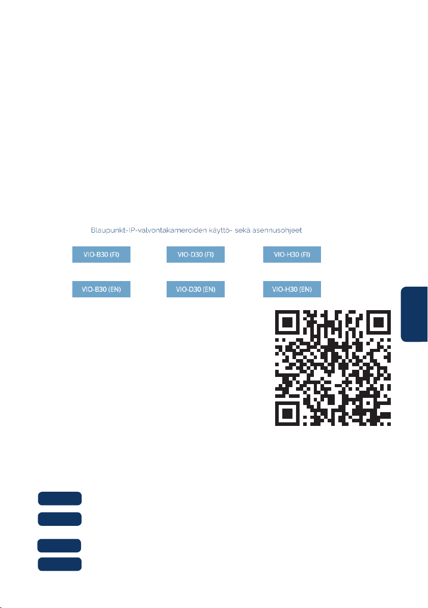
Mene osoitteeseen: https://www.greenmoore./kayttoohjeet
1. Katso kohdasta “Blaupunkt-IP-valvontakameroiden käyttö- sekä asennusohjeet”
2. “VIO” kameroiden ohjeet ovat kukin omassa laatikossaan
3. Klikkaa haluamasi VIO-kameramallin laatikkoa
4. Selaimeen latautuu PDF-muotoinen käyttöopas
5. Tallenna tiedosto halutessasi omalle laitteellesi myöhempää käyttöä varten
6.4 Asiakastuki ja palautukset
Löydät ohjevideoita asennuksesta ja QR-koodin
käytöstä YouTube-kanavaltamme, jonne pääset
skannaamalla tämän QR-koodin. Valitse oman kielesi
mukainen soittolista kanavalta.
Paina nollauspainiketta (katso kappale 2) 15 sekunnin ajan kunnes
punainen valo syttyy ja alkaa vilkkua.
Odota kunnes vihreä merkkivalo alkaa vilkkua hitaasti.
Kamera on palautettu oletusasetuksiinsa.
Vaihe 2:
Vaihe 3:
Vaihe 4:
Palautukset: Jos haluat palauttaa kamerasi, kehoitamme vahvasti että poistat tiliisi
yhdistetyt kamerat sovelluksessa ennen kameran palauttamista.

TECHNICAL SPECIFICATION VIO-D40:
• Image sensor: 1/3” 4 Megapixel progressive CMOS
• Resolution: 2304×1296
• Video: H.264 encoding 20fps@4M(2304×1296) & 25/30fps@2M (1920×1080)
• Lens: 2.8mm F2.0
• Angle of View: Horizontal 100˚, Vertical 55˚
• Digital Zoom: 16x
• Minimum Illumination : 0.1Lux(Color), 0Lux(B/W)
• Wireless Interface: Wi-Fi(IEEE802.11b/g/n), 50m(open eld)
• IR LEDs: 24
• Power Input: DC12V
• Operating Temperature: -20°C ~ +50°C
• Operating Humidity: Up to 95% non-condensing
• Ingress Protection: IP67
• Dimensions: 109.9 x 109.9mm x 81mm
• Video stream encryption: TLS