Loading ...
Loading ...
Loading ...
13
HIGH TEMPERATURE CUTOUT
REPLACEMENT
WARNING: Disconnect power before attempting any
maintenance or cleaning to reduce the risk of electric
shock or damage to persons.
CAUTION: If unit was operating prior to servicing allow
at least 10 minutes for lights and heating elements to cool
off to avoid accidental burning of skin.
Tools required: Phillips head screwdriver
CAUTION: Follow “Preparation for Service” instructions
before proceeding.
1. Remove the decorative acrylic ember-bed pieces from
the media tray, which lies along the bottom of the interi-
or Partially Reective Glass. A medium sized container
such as a bucket or a box will be needed to keep the
acrylic ember-bed pieces together.
!
NOTE: Try to ensure the pieces do not get pushed or
wedged underneath the Partially Reective Glass. They
may obstruct the ease of removing the Partially Reective
Glass from the replace.
2. Remove the Partially Reective Glass retaining brack-
ets by removing the 3 screws on each brackets; (3
brackets in total), located on the left and right side of
the Partially Reective Glass. (Figure 14)
3. Remove the Partially Reective Glass. Carefully place
the glass assembly aside in a safe location.
4. Remove the remaining screw, that secures the controls
assembly (Figure 9), located at the top of the mirror on
the right side of the unit.
5. Slide the controls assembly out toward the front of the
unit.
CAUTION: Ensure that the assembly is removed care-
fully, ensuring that no wires are caught or over strained.
6. Remove the heating cover by removing the 4 screws: 2
on the left and 2 on the right of the tray. (Figure 14)
7. Locate the high temperature cutout and remove the
mounting screw.
8. Remove the 2 screws, that secure the controls assem-
bly (Figure 9), located at the top of the mirror on the
right side of the unit.
9. Slide the controls assembly out toward the front of the
unit.
CAUTION: Ensure that the assembly is removed care-
fully, ensuring that no wires are caught or over strained.
10. Disconnect the wiring connections noting their original
locations.
!
NOTE: Using a at head screwdriver gently pry between
the end of the connectors and the board to release the
wires.
11. Properly orient the new high temperature cutout and
connect all of the wiring connections.
12. Reassemble in the reverse order as above.
ELEMENT REPLACEMENT
WARNING: Disconnect power before attempting any
maintenance or cleaning to reduce the risk of electric
shock or damage to persons.
CAUTION: If unit was operating prior to servicing allow
at least 10 minutes for lights and heating elements to cool
off to avoid accidental burning of skin.
Tools required: Phillips head screwdriver.
Needle nosed pliers.
CAUTION: Follow “Preparation for Service” instructions
before proceeding.
1. Remove the decorative acrylic ember-bed pieces from
the media tray, which lies along the bottom of the interi-
or Partially Reective Glass. A medium sized container
such as a bucket or a box will be needed to keep the
acrylic ember-bed pieces together.
!
NOTE: Try to ensure the pieces do not get pushed or
wedged underneath the Partially Reective Glass. They
may obstruct the ease of removing the Partially Reective
Glass from the replace.
2. Remove the Partially Reective Glass retaining brack-
ets by removing the 3 screws on each brackets; (3
brackets in total), located on the left and right side of
the Partially Reective Glass. (Figure 14)
3. Remove the Partially Reective Glass. Carefully place
the glass assembly aside in a safe location.
4. Remove the remaining screw, that secures the controls
assembly (Figure 9), located at the top of the mirror on
the right side of the unit.
5. Slide the controls assembly out toward the front of the
unit.
CAUTION: Ensure that the assembly is removed care-
fully, ensuring that no wires are caught or over strained.
6. Remove the heating cover by removing the 4 screws: 2
on the left and 2 on the right of the tray. (Figure 14)
7. From the top panel of the heating assembly housing,
remove the 4 screws that hold the element cover to the
housing panel.
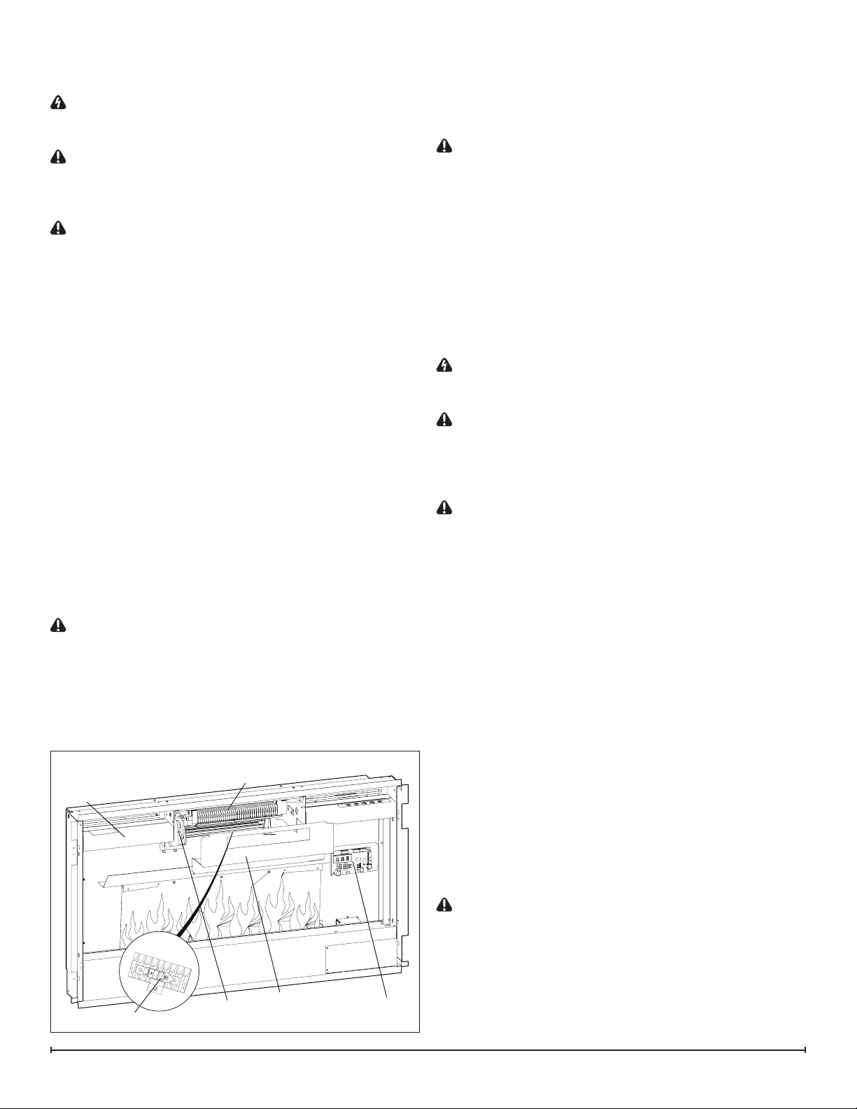
Figure 14
Heating
Elements
Cutout
Blower
Assembly
Heating
Cover
Cover Panel
Display/Control
Board
Loading ...
Loading ...
Loading ...