
Part Number 7113995 / ENGLISH
REV 3
- 04/20/2022
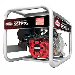
Models covered: SSTP02 / STP03
SAVE THIS MANUAL FOR FUTURE REFERENCE
USE AND CARE MANUAL
READ THIS MANUAL CAREFULLY BEFORE OPERATION
Failure to follow the instructions and safety precautions in this manual can result
in property damage, serious injury and/or death.
NOTE: Photographs and line drawings used in this manual are for
reference only and may not represent your specic model.
SEMI-TRASH
WATER PUMP

Page II
NOTES
THIS PAGE WAS INTENTIONALLY LEFT BLANK
Page 1
Save this manual for future use
Write down the model number, serial number, and purchase date of this product in the spaces
provided below then keep this manual with the purchase receipt(s) for future reference.
Keep this manual for future reference. This manual should be considered a permanent
part of the product and stay with it. This manual should be available to anyone operating
the product(s) it covers. This manual should remain with the product(s) it covers if sold
to a new owner. If the manual becomes damaged, lost, or otherwise unusable, please
contact customer support by calling 1-877-362-4271 or emailing [email protected]
to request a new copy.
Model Data Decals
Model Number:
Serial Number:
Purchase Date:

Page 2
TABLE OF CONTENTS
NOTES ............................................................................................II
Save this manual for future use....................................................................................1
TABLE OF CONTENTS ..................................................................2
SAFETY INSTRUCTIONS ..............................................................4
Read This Manual Before Operating ............................................................................4
Additional Instructions ..................................................................................................4
Hazard Alert Symbols ................................................................................................... 4
DISCLAIMERS ................................................................................5
UNPACKING ...................................................................................5
COMPONENT LOCATION ..............................................................6
OPERATING CHECKLIST ..............................................................7
Location ........................................................................................................................ 7
High Altitude Operation ................................................................................................8
Operating Conditions....................................................................................................8
Checking the Engine Oil ............................................................................................... 9
Checking Fuel ............................................................................................................11
CONNECTING HOSES .................................................................13
Connecting Suction and Discharge Hoses ................................................................. 13
Connecting Suction Hose Strainer .............................................................................14
Hose Placement .........................................................................................................14

Page 3
PRIMING THE PUMP ....................................................................15
Priming the pump .......................................................................................................15
STARTING ....................................................................................16
Starting the Engine ..................................................................................................... 16
SHUTTING OFF ENGINE .............................................................17
MAINTENANCE ............................................................................18
Pump maintenance ...................................................................................................18
Engine Maintenance...................................................................................................20
STORAGE AND TRANSPORTATION ..........................................20
Storing for two months or less .................................................................................... 20
Storing for more than two months ..............................................................................21
Transportation ............................................................................................................21
SPECIFICATIONS .........................................................................22
Model Number: SSTP02 / Item Number: 71002.........................................................22
Model Number: STP03 / Item Number: 71003 ...........................................................22
WARRANTY ..................................................................................23
Page 4
This manual contains important safety information and instructions. Do not operate
this product until you have read and completely understand all safety, operation, and
maintenance instructions listed in this manual. Failure to follow the information listed in
this manual before operation will result in property damage, injury, and/or death.
NOTE: The warnings and precautions discussed in this manual cannot cover all conditions
and situations that may occur. The operator must understand awareness and caution are
factors which cannot be built into this product and so must be exercised by the operator.
Read This Manual Before Operating
Additional Instructions
Be sure to understand the safety symbols and denitions listed below. Each symbol contains
one of four words: DANGER, WARNING, CAUTION, NOTICE each of these words indicates
a dierent level of hazard severity. These symbols are used throughout this manual with
information about specic hazard, the consequences of the hazard, and instructions on how
to avoid the hazard. Failure to heed these symbols and the instructions provided with them
will result in property damage, injury, and/or death.
Hazard Alert Symbols
Indicates an imminently dangerous situation which, if not
avoided, will result in property damage, serious injury, and/
or death.
Indicates a potentially hazardous situation which, if not
avoided, could result in property damage, serious injury, and/
or death.
Indicates a hazardous situation, which if not avoided, could
result in property damage and/or minor to moderate injury.
Indicates information considered important but not directly
hazard related.
SAFETY INSTRUCTIONS
Along with this manual, be sure to read any additional instructions provided both on and
with the product, attached equipment, accessories, and the engine powering the product.
Pay careful attention to all additional safety rules and instructions on proper startup,
operation, and shutdown procedures. Always use any protective apparel that may be
needed to operate the equipment safely.
● All information in this publication was based on the latest product information available
at the time of printing. The FNA Group reserves the right to change, alter, and/or
improve the product and this document at any time, without notice, and without incurring
any obligation.
● The pictures and gures in the manual should be used for reference only. There may be
dierences between the pictures, drawings, gures, and the physical product.
● This pump may be equipped with a spark arrestor muer. The spark arrestor must be
maintained in eective working order by the owner/operator. In the State of California,
a spark arrestor is required by law (Section 4442 of the California Public Resources
Code). Other states may have similar laws. Federal laws apply on federal lands.
1. Place the shipping carton on a solid, at surface.
2. Carefully cut the top of the carton open.
3. Carefully cut each corner of the carton from top to bottom.
4. Lay each side of the carton at on the ground.
5. Remove everything from the carton.
Follow the steps outlined in this section to unpack and assemble your pump. If you have
any questions regarding the unpacking or assembly of your pump, please have your model
number and serial number ready, then contact customer support at 1-877-362-4271 or
email [email protected].
Page 5
UNPACKING
DISCLAIMERS
This product and the engine exhaust can expose you to chemicals which are known to
the state of California to cause cancer, birth defects, or other reproductive harm. For more
information on California Proposition 65, go to www.P65Warnings.ca.gov.
CALIFORNIA PROPOSITION 65 WARNING
POLYCYCLIC AROMATIC HYDROCARBON WARNING
The air lter element and air box assembly may contain polycyclic aromatic hydrocarbons
(PAHs). Some PAHs may cause cancer. To avoid exposure to PAHs, wear gloves when
performing air lter maintenance.
Page 6
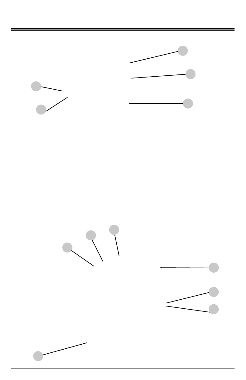
1
2
3
4
5
6
7
8
10
9
11
12
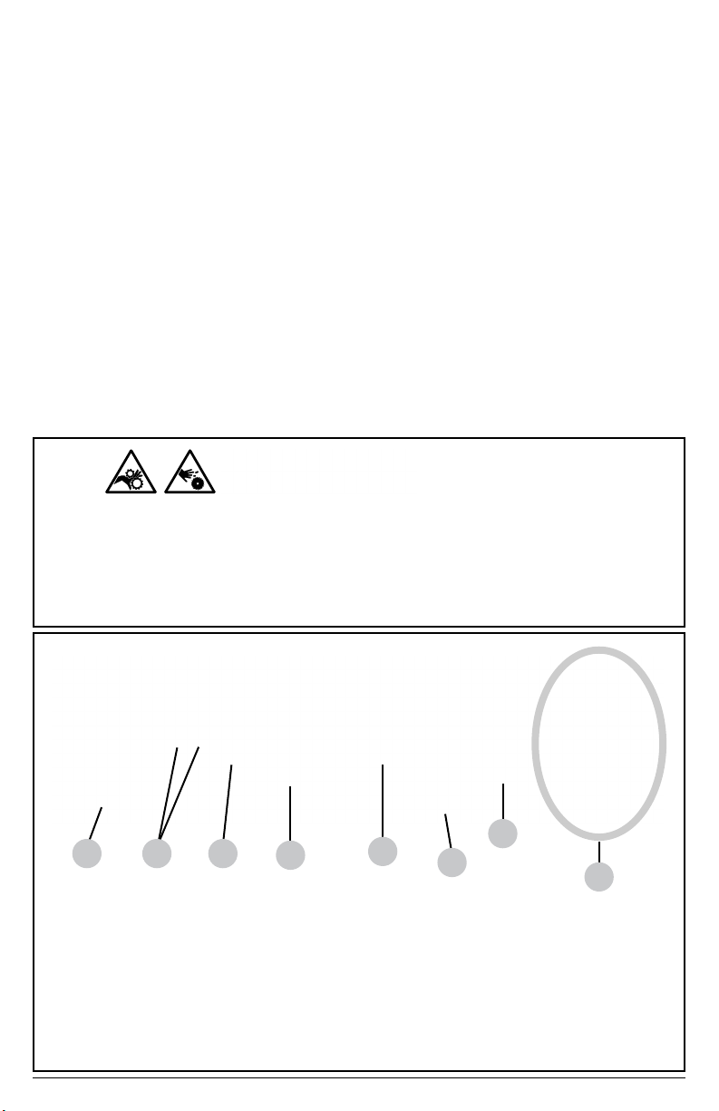
1. Primer funnel
2. Discharge port
3. Suction port
4. Engine ignition switch
5. Starter recoil
COMPONENT LOCATION
6. Fuel tank
7. Fuel level indicator
8. Fuel tank cap
9. Fuel tank valve
10. Engine choke
11. Engine fuel valve
12. Pump drain plug
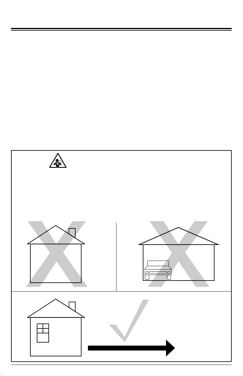
TOXIC FUMES
Engine exhaust contains carbon monoxide, an odorless, colorless, poisonous gas.
Running an engine indoors will kill you in minutes. Never use this product inside a house,
garage, or any other kind of enclosure even if doors and windows are open. Run engine
outside at least 20 feet (6 meters) away from windows, doors, and vents. Carefully
consider wind direction and air currents when using this product outside to avoid breathing
in engine exhaust. Always use a carbon monoxide detector in any occupied buildings
near the running engine.
Page 7
OPERATING CHECKLIST
Location
Place the pump on a level surface outside in a well-ventilated area before any operation.
Keep all ammable materials at least ve feet away from all sides of the product.
● Never use pump inside a house, garage, or any other kind of enclosure even if doors and
windows are open. Run engine outside at least 20 feet (6 meters) away from windows,
doors, and vents. Carefully consider wind direction and air currents when using pump
outside to avoid breathing in engine exhaust.
● Following the manufacturer’s instructions and recommendations, install a battery
operated carbon monoxide alarm in any occupied buildings near the running engine.
● If you experience headache, nausea, dizziness, sleepiness, or weakness while pump is
running, move to fresh air and seek medical attention immediately.
INSPECT BEFORE OPERATING
Page 8
Failure to inspect this product before use could result in a hazardous situation resulting
in product damage serious injury and/or death. To avoid these hazards, inspect the pump
before each use. Check for loose or damaged parts, signs of oil or fuel leaks, missing
guards, plugged cooling vents, or any other condition that may aect proper operation.
Repair or replace all damaged or defective parts and keep all safety guards in place and
in proper working order before using the pump.
UNTRAINED OPERATION
Untrained persons, young children, and pets can be seriously injured or killed if allowed
to incorrectly operate or play with running pump. Be sure anyone operating the pump
receives proper instructions, understands safe operation, and has read the owner’s
manual before operating this product. Do not let children operate the pump without
parental supervision. Keep young children and pets away from the pump while it is
running. Always turn o the pump before leaving the area.
High Altitude Operation
This engine will have proper engine performance and emission control when it is operated
at or below an altitude of 5000 feet (1524 meters). This engine requires a high-altitude
carburetor kit to ensure proper engine performance and emission control when operated
at altitudes above 5000 feet (1524 meters). Operating the engine with the wrong engine
conguration above 5000 feet (1524 meters) may increase its emissions and decrease
fuel eciency, and hurt performance. To obtain a high altitude carburetor kit, contact your
nearest authorized service center.
Operating Conditions
Before each use, check for loose or damaged parts, oil or fuel leaks, and/or any other
condition that may aect proper operation. Repair or replace all damaged or defective parts
immediately. Always keep all safety guards in place and in proper working order. For safety
reasons, the manufacturer recommends all maintenance and repairs be performed by an
authorized service center.
Before starting engine, remove any excessive dirt and debris especially from any cooling
vents, exhaust and muer, and starter recoil areas. Never move or tip the pump while
operating. Use pump only for its intended purpose. If you have questions about the proper
use of your pump, please contact customer support at 1-877-362-4271 or cservice@fna-
group.com.
Operating the engine with a high-altitude carburetor jet kit at an altitude below 5000 feet
(1524 meters) will cause the engine to run too hot. Overheating the engine could result in
serious engine damage. To avoid damaging the engine, make sure the correct carburetor
kit is installed and the air/fuel mixture is correctly set for your altitude.
ALTITUDE
MOVING PARTS
This product has many parts that move at high speeds. Moving parts can cause crushing
injuries, broken bones, severe lacerations, and/or traumatic amputations. To prevent
injury, never place ngers, hands, feet, or other body parts near running engine. Never
operate product with covers, shrouds, or other guards removed. Do not wear loose-tting
clothing, dangling drawstrings, or any other hanging items that could become entangled
in moving parts while operating. Tie up long hair and remove jewelry before operating.
Page 9
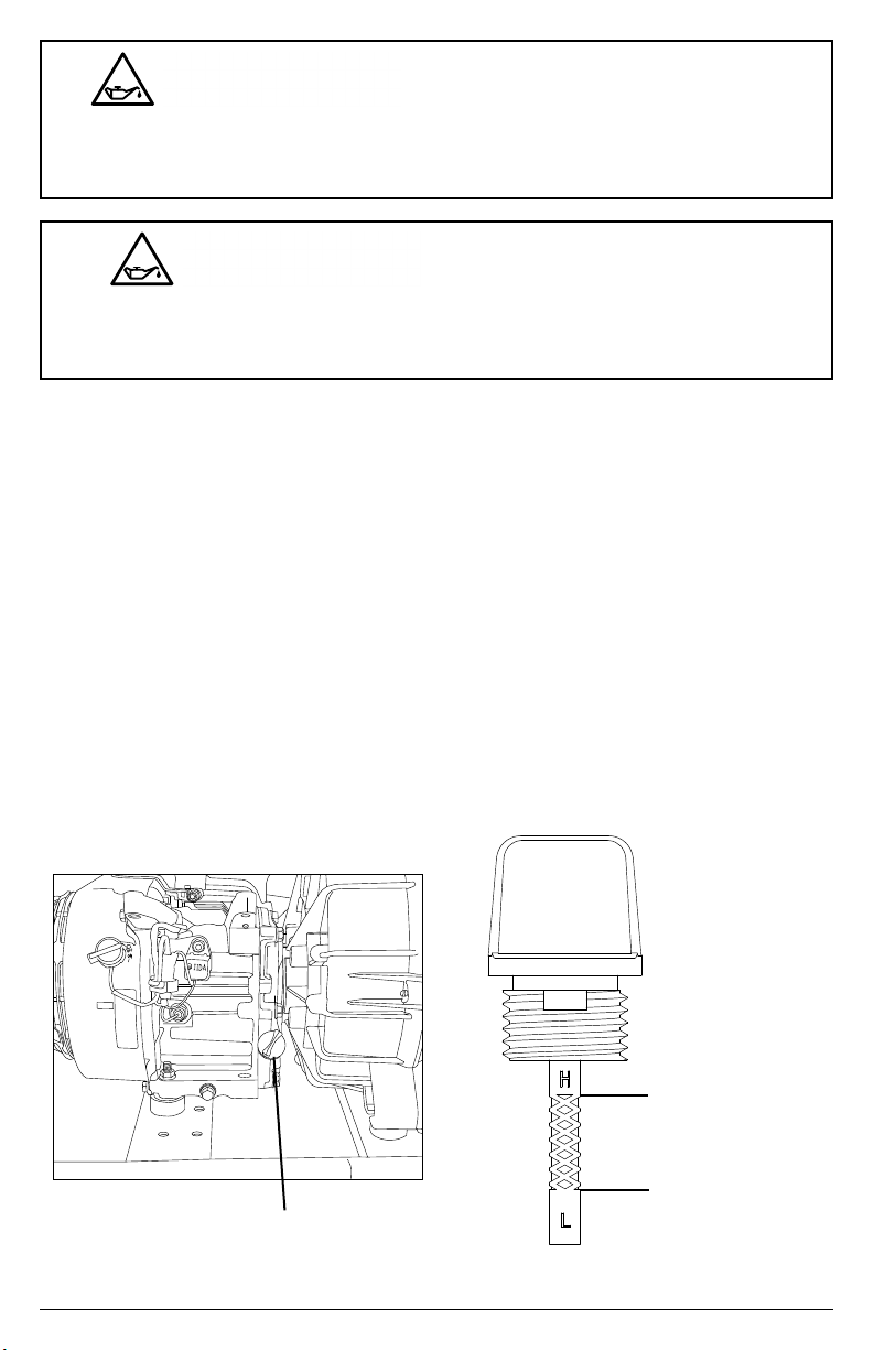
Checking the Engine Oil
The low oil sensor (if equipped) will automatically stop the engine when the oil level falls
below the safe limit. To avoid an unexpected shutdown, check the oil level regularly, ll to
the upper limit, and always operate engine on a level surface.
LOW OIL SENSOR
HOT SURFACES
A running engine produces heat. The surfaces of the engine, other related components,
and engine exhaust gas get hot enough to cause mild moderate burns or ignite materials
on contact. To avoid burns, do not touch engine surfaces or exhaust gases while
operating and allow engine to cool completely before moving, touching, or performing
any maintenance. To avoid a re, keep all ammable materials at least ve feet away
from all sides of the product.
Hot oil can cause serious burns. To prevent getting burned when changing or checking
the engine oil, use gloves to prevent oil to contact skin and change the oil when the
engine is warm from operating but not hot.
HOT OIL
HOT SURFACES
A running engine produces heat. The surfaces of the engine, other related components,
and engine exhaust gas get hot enough to cause mild moderate burns or ignite materials
on contact. To avoid burns, do not touch engine surfaces or exhaust gases while
operating and allow engine to cool completely before moving, touching, or performing
any maintenance. To avoid a re, keep all ammable materials at least ve feet away
from all sides of the product.
Page 10
The engine is shipped from the factory without oil. Running the engine without oil will
result in severe engine damage and void the warranty. To avoid causing engine damage
and voiding the warranty, ll the engine with the recommended oil type.
FILL ENGINE OIL BEFORE USE
1. Check oil with pump on a level surface with the engine o.
2. Remove the dipstick by unscrewing the gray cap and pulling it out, then wipe it clean.
3. Place clean dipstick into engine, but do not thread it in, leave it rest it on the ller neck.
4. Remove the dipstick from ller neck and check oil level. Oil level should be at the high
mark on the dipstick.
5. If level is low, add the recommended oil to the crankcase until the level reaches the
upper limit on the dipstick. See the engine manual for recommended oil.
6. Install the dipstick and tighten cap by threading it into the ller neck.
Engine Oil Dipstick
Upper Oil Limit
Lower Oil Limit
USE CORRECT ENGINE OIL
Oil is a major factor in the performance and service life of any engine. Using the incorrect
oil may damage the engine and void the warranty. To avoid causing engine damage and
voiding the warranty, check and change oil as required using the correct engine oil.
Page 11
Gasoline vapor can build up inside the fuel tank creating pressure. This pressure may
increase when the engine is hot from running. Opening the fuel tank under pressure can
cause rapid escape of ammable vapors and possible fuel spills that may ignite from
contact with hot engine surfaces resulting in burn hazard. To avoid these hazards, always
allow the engine to cool for at least 2 minutes before removing fuel cap and loosen the
fuel cap slowly to relieve any pressure in the tank.
FUEL TANK PRESSURE
Checking Fuel
REFUELING
Gasoline is highly ammable and gasoline vapors are extremely explosive. Fire and
explosions can cause severe burns and/or death. Keep gasoline away from ames,
sparks, and other ignition sources. Refuel outdoors in a well-ventilated area with the
engine stopped and cool. Wipe up any spilled gasoline and allow engine to dry before
starting. Keep a re extinguisher handy while refueling. Do not operate engine with leaks
in the fuel system. Do not store gasoline near other ammable materials.
Old gasoline can create deposits that clog fuel systems causing hard starting and poor
performance. Damage caused by old fuel is not covered by warranty. To minimize
deposits, avoid old fuel related performance issues, and prevent costly repair work, do
not use gasoline that is older than 30 days.
OLD FUEL
Using gasoline with an alcohol blend greater than 10% (E10) will damage the engine.
Damage caused by using an alcohol blend of 15% (E15), 85% (E85), or any other alcohol
blend higher than 10% (E10) is not covered under warranty. To avoid engine damage
caused by an alcohol blend that is too high, use gasoline with 10% (E10) alcohol or lower.
ALCOHOL BLENDS
The use of fuel system cleaning additives can damage the engine and fuel systems.
Damage caused by the use of fuel system cleaning additives is not covered by warranty.
To avoid engine and fuel system damage, do not use any fuel system cleaning additives.
FUEL ADDITIVES
Page 12
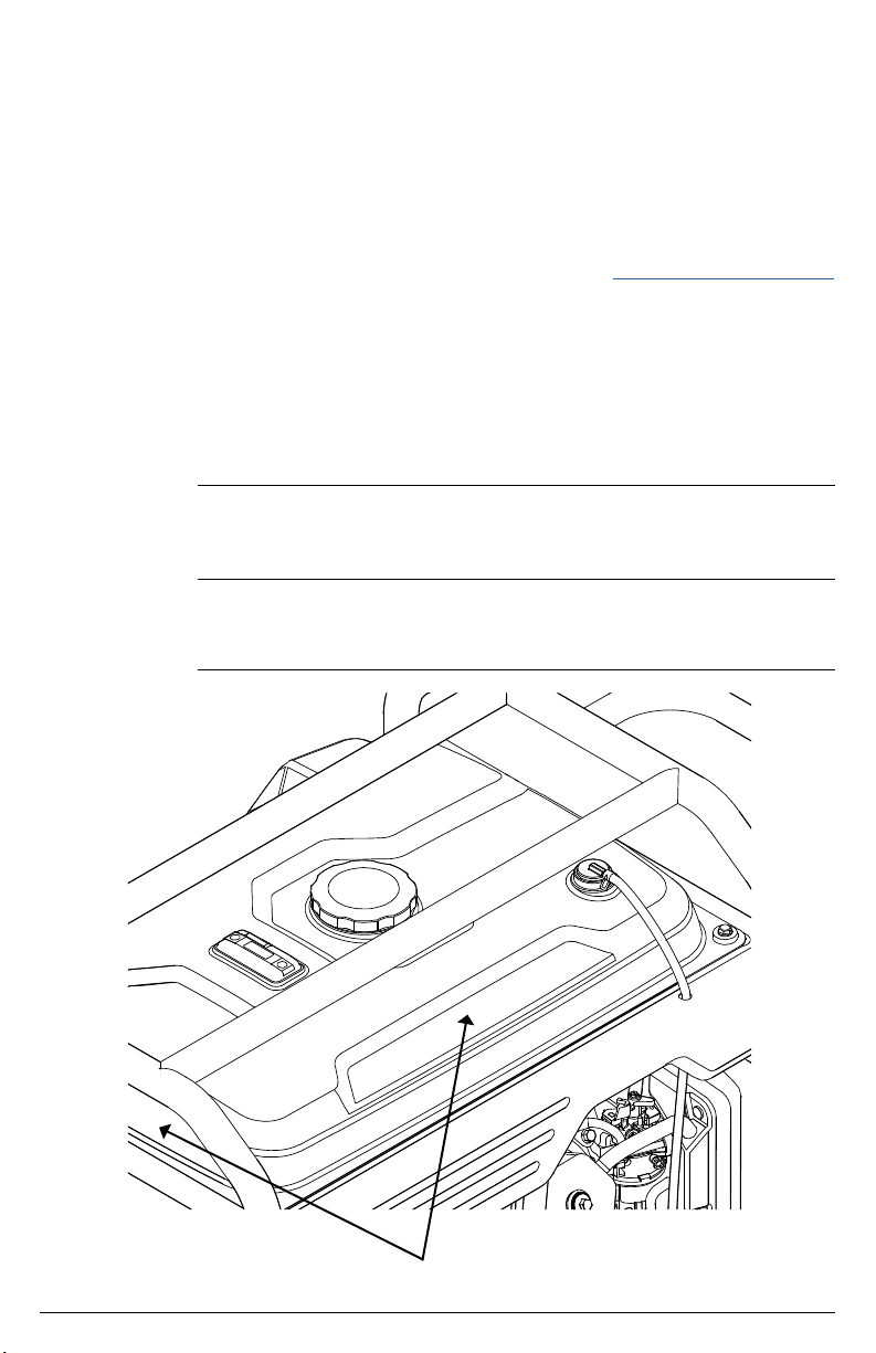
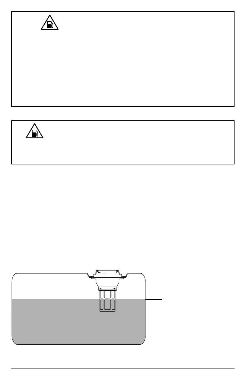
DO NOT OVERFILL FUEL TANK
Overlling the fuel tank can result in carbon canister damage (if equipped), poor engine
performance, and void the warranty. To avoid these hazards, do not ll the fuel tank
above the maximum level.
1. Check fuel with pump on a level surface with the engine o.
2. Read fuel gauge and ll fuel tank if needed. For fuel gage location see the COMPONENT
LOCATIONS section of this manual.
3. Do not use gasoline that is older than 30 days. Use only clean and fresh regular
unleaded gasoline with a minimum octane rating of 87. Do not mix oil with gasoline. Do
not use gasoline that contains more than 10% ethyl alcohol. E15, E20, and E85 are not
approved fuels and should not be used.
4. Do not to ll the fuel tank above the maximum fuel level to allow room for fuel expansion.
For fuel capacity see the SPECIFICATIONS section of this manual.
Maximum Fuel Level
It is important to prevent gum deposits from forming in essential fuel system parts, such
as the carburetor, fuel lter, fuel hose or tank during storage. Alcohol-blended fuels (also
called gasohol, ethanol, or methanol) attract moisture, which leads to separation and
formation of acids during storage. Acidic fuel and gum deposits can damage the engine’s
fuel system while in storage. Eects of old, stale, or contaminated fuel are not covered
under warranty.
NOTE: Using a fuel stabilizer (sold separately) when storing gasoline will help prevent
problems related to ethanol alcohol in outdoor power equipment engines. Always follow
the instructions provided by the fuel stabilizer manufacturer to mix and use correctly.
GASOLINE STORAGE
1
2
6
7
8
9
10
3 4
5
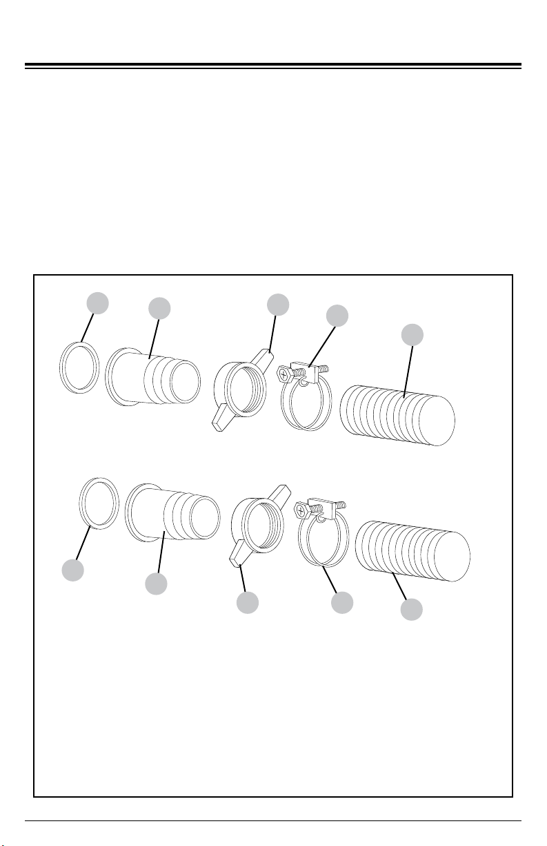
1. Suction port gasket
2. Suction hose barb
3. Suction hose barb nut
4. Suction hose clamp
5. Suction hose (not included)
6. Discharge port gasket
7. Discharge hose barb
8. Discharge hose barb nut
9. Discharge hose clamp
10. Discharge hose (not included)
Page 13
CONNECTING HOSES
Connecting Suction and Discharge Hoses
1. Place gaskets and hose barbs onto both the suction and discharge ports then secure by
threading on hose barb nuts.
2. Attach the suction hose (not included) to the suction port by sliding the hose over the
barb then securing it with a hose clamp.
3. Attach the discharge hose (not included) to the discharge port by sliding the hose over
the barb then securing it with a hose clamp.
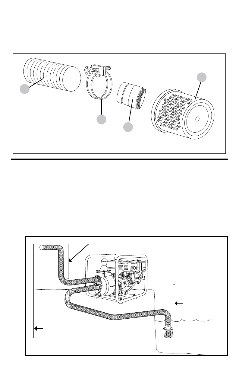
1
2
3
4
1. Suction hose
2. Strainer hose clamp
3. Strainer barb
4. Strainer
Suction head lift
Total head lift
Discharge head lift
Page 14
Connecting Suction Hose Strainer
1. Thread the strainer barb into the strainer.
2. Place the suction hose over the strainer barb and secure it with a strainer hose clamp.
Hose Placement
1. Place pump on a level surface.
2. Completely immerse strainer but do not rest it on the bottom of the water source.
3. Do not exceed the maximum suction head and total head lifts as listed in the
SPECIFICATIONS section of this manual.
NOTE: The suction head lift should always be less than the discharge head lift.
This pump will not prime when dry. Running the pump dry without priming can damage
the pump assembly and seals. Damage caused by running dry is not covered under
warranty. To avoid damaging the seals and pump assembly, do not run the pump when
it is dry without priming.
PUMP PRIMING
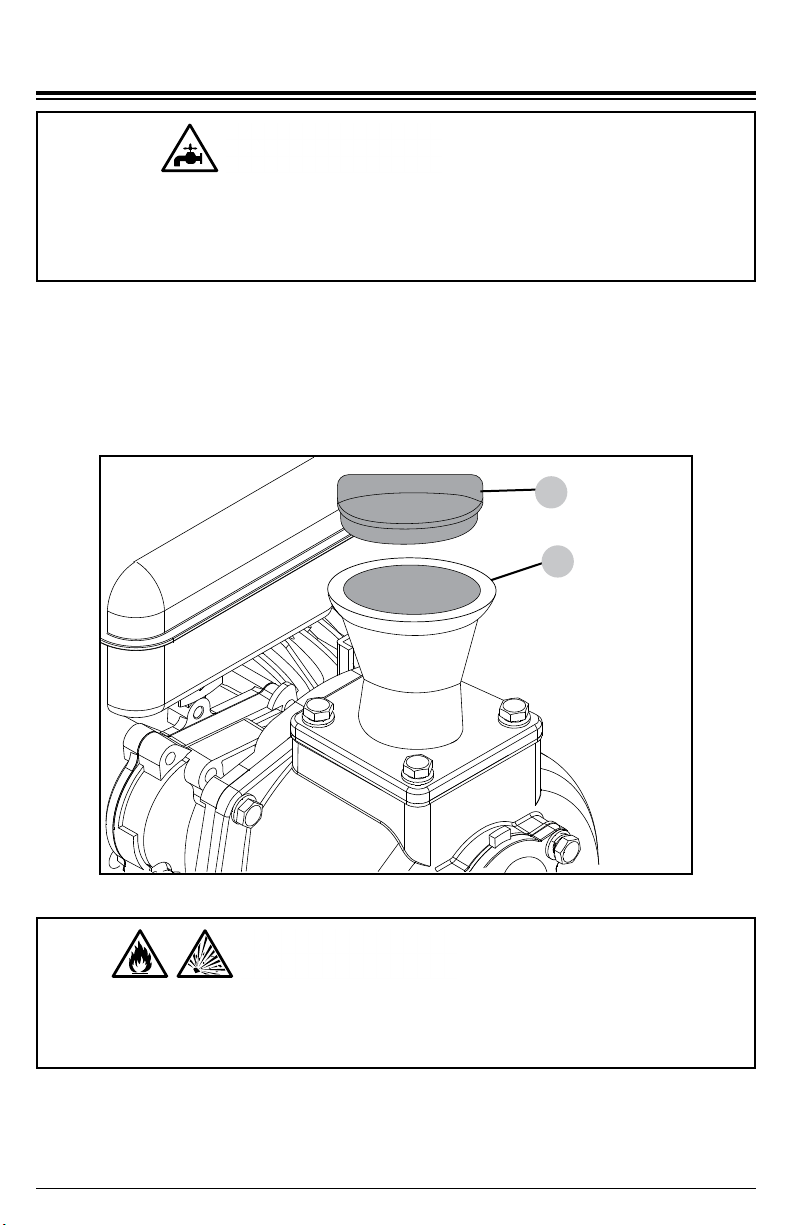
2
1
1. Primer funnel cover
2. Primer funnel
Page 15
PRIMING THE PUMP
Priming the pump
1. Remove primer funnel cover.
2. Pour water into the primer funnel until pump is full of water.
VOLATILE LIQUIDS
Pumping volatile, ammable, or corrosive liquids could cause pump damage, re, or
explosion resulting in severe injury and/or death. To avoid these hazards, do not attempt
to pump volatile, ammable, or corrosive liquids.
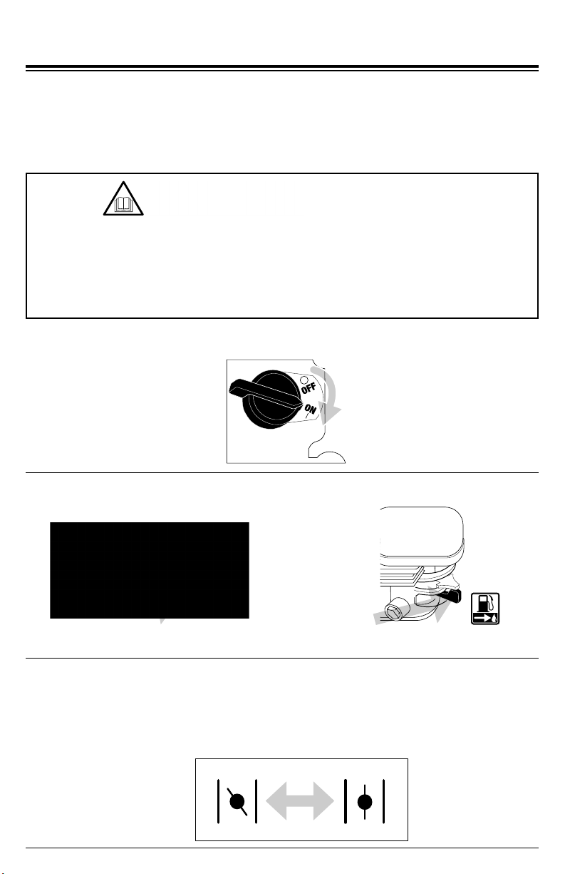
OPENCLOSED
Tank fuel valve Engine fuel valve
Page 16
STARTING
Starting the Engine
1. Complete the steps in the OPERATING CHECKLIST, CONNECTING HOSES, and
PRIMING THE PUMP sections of this manual before starting the engine. Failure to do
so could damage your engine and pump.
2. Turn the engine ignition switch to the ON position.
3. Turn the tank and engine fuel valves to their ON positions.
4. Adjust choke as needed:
NOTE: The starting position of the choke will vary depending on the engine temperature. If
starting a cold engine, move the choke lever towards the closed position. If starting a warm
engine, move the choke lever towards the open position.
Attempting to start the engine incorrectly or using the pump incorrectly can result in
engine and/or pump damage, and may cause serious injury or death. To avoid engine
and/or pump damage and serious injury or death be sure to read, understand, and follow
the steps outlined in the OPERATING CHECKLIST section of this manual before starting
the engine, and follow all the guidelines for proper use of the pump.
OPERATING CHECKLIST
OPENCLOSED
Page 17
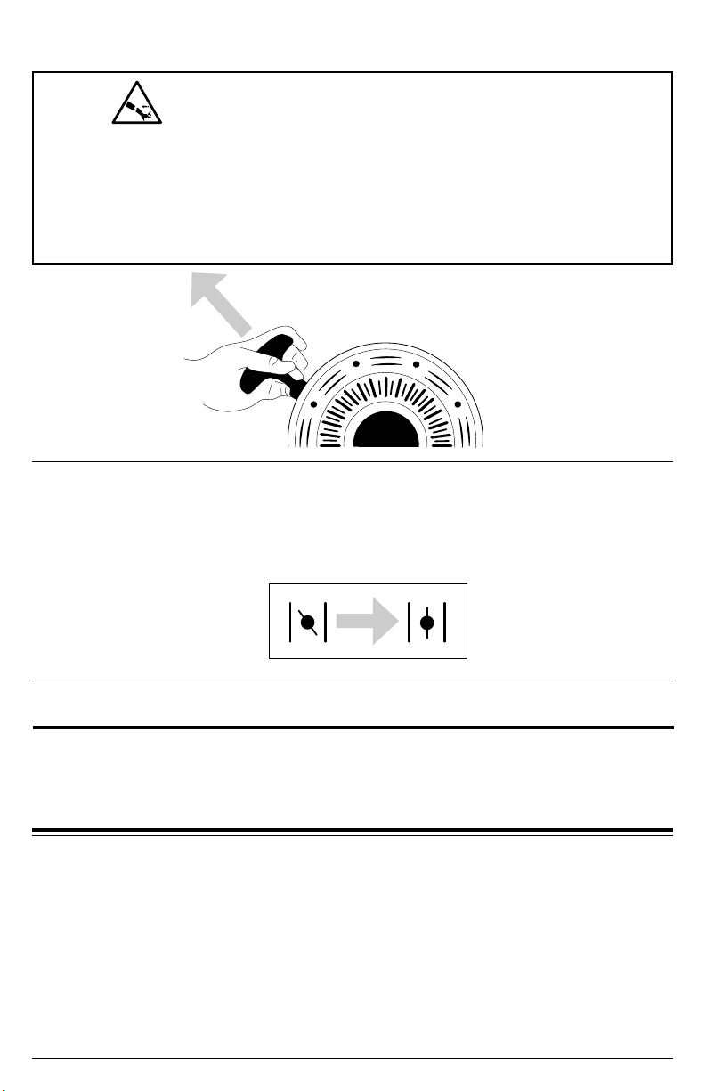
5. Pull the recoil until you feel some resistance, then pull rapidly to start the engine.
6. Adjust choke as needed:
NOTE: Once the engine starts, slowly move the choke lever to the OPEN position as the
engine warms. If engine falters, move choke towards the CLOSED position until the engine
is warmed up.
RAPID RETRACTION
Rapid retraction (also known as kickback) of the engine recoil starter cord will pull your
hand and arm towards the engine faster than you can let go of the handle resulting in
sprains, broken bones, lacerations, and/or traumatic amputations. Kickback is caused
by damage to the engine crankshaft key, compression release failure, and/or improper
starting techniques. To avoid kickback follow the appropriate maintenance schedule,
starting instructions, and have repair work done by an authorized service center.
1. Turn the ignition switch to the OFF position.
2. Turn the tank and engine fuel valves to the OFF positions.
3. Allow the engine to cool completely before handling and storing.
SHUTTING OFF ENGINE
Page 18
MAINTENANCE
For safety reasons, the manufacturer recommends all pump service and repairs be
performed by an authorized service center. All warranty replacements or repairs must be
performed by an authorized distribution or service center. To nd an authorized service
center near you, to make a warranty claim, or for authorized warranty repair, call 1-877-362-
4271 or email [email protected].
It is the responsibility of the owner and/or operator to have all scheduled maintenance
completed before operating the pump. Be sure to follow the inspection and maintenance
recommendations as listed in all the manuals that came with this unit.
Pump maintenance
Maintenance: Before each use, check pump for loose or damaged parts, and any other
condition that may aect proper operation. Be sure all safety guards are in place and in
proper working order. Inspect all air vents and cooling slots to ensure they are clean and
unobstructed. Repair or replace all damaged or defective parts immediately. For safety
reasons, the manufacturer recommends all pump service and repairs be performed by an
authorized service center. To nd an authorized service center near you, obtain information
about how to make a warranty claim, or to make arrangements for authorized warranty
repairs, please call 1-877-362-4271 or email [email protected].
Exterior Pump Cleaning: Always clean the pump with the engine o and cool. To clean
the pump, rst use an air compressor set at 25 PSI to clear dirt and debris from the pump
surfaces, vents, and cooling slots. Then, wipe the exterior clean with a damp cloth.
Water can damage the pump engine components if allowed to enter through cooling
slots or other holes. Damage caused by water intrusion is not covered under warranty.
To avoid engine water damage, do not use a pressure washer, garden hose, or any
other sources of running water to clean the pump engine, and never submerge the pump
engine in any liquids.
Using chemical cleaners and/or corrosive liquids can damage the pump seals and internal
components. Damage caused chemical cleaners and corrosive liquids is not covered
under warranty. To avoid damaging pump seals and components, do not use chemical
cleaners and corrosive liquids to clean the components inside of the pump housing.
CLEANING
CHEMICAL CLEANERS
Improper engine and pump maintenance and failing to correct problems before operation
could void the warranty and may result in property damage and injury. To prevent these
hazards, follow the maintenance procedures listed in this manual and any other manual
that came with this product.
MAINTENANCE
4
5
678
3
2
1
1. Pump housing drain plug
2. Outer pump housing bolts
3. Outer pump housing
4. Check valve
5. Impeller housing
6. Impeller
7. Impeller seal assembly
8. Inner pump housing
MOVING PARTS
This product has many parts that move at high speeds. Moving parts can cause crushing
injuries, broken bones, severe lacerations, and/or traumatic amputations. To prevent
injury, never place ngers, hands, feet, or other body parts near running engine. Never
operate product with covers, shrouds, or other guards removed. Do not wear loose-tting
clothing, dangling drawstrings, or any other hanging items that could become entangled
in moving parts while operating. Tie up long hair and remove jewelry before operating.
Page 19
Interior Pump Cleaning: Keeping your trash pump clean will allow it to perform its best and
prolong the life of the pump. Do not store the trash pump with without draining the pump
housing. Do not allow dirt and debris to dry inside the pump housing. Clean your trash pump
after each use by following the steps below.
1. Remove the pump housing drain plug and allow water to drain.
2. Remove the outer pump housing cover bolts.
3. Remove the outer pump housing cover and its rubber seal.
4. Remove the check valve.
5. Remove the impeller housing and its rubber seal.
6. Remove all dirt and debris from the components then rinse them clean with water. Do not
use chemicals to clean the internal pump components as they may damage the seals.
7. Reassemble all components making sure all rubber seals are in their proper locations
and do not get pinched or damaged during reassembly.
Page 20
Engine Maintenance
Before each use, check engine for loose or damaged parts, signs of oil or fuel leaks, and/or
any other condition that may aect proper operation. Always keep all safety guards in place
and in proper working order. Repair or replace all damaged or defective parts immediately.
For safety reasons, the manufacturer recommends all engine service and repairs (including
emission control devices and systems) be performed by an authorized service center.
All warranty replacements or repairs must be performed by an authorized distribution or
service center. To nd an authorized service center near you, obtain information about how
to make a warranty claim, or to make arrangements for authorized warranty repairs, please
call 1-877-362-4271 or email [email protected].
For all other information on engine maintenance, refer to the engine manual.
STORAGE AND TRANSPORTATION
Storing for two months or less
1. Fill fuel tank per the OPERATING CHECKLIST section of this manual then add a fuel
stabilizer per the manufacturer’s recommendations.
2. Start the engine per the STARTING section of this manual and run it for ten (10) minutes
to allow the stabilized fuel to circulate through the entire fuel system.
3. With the engine still running, turn the fuel valve to the OFF position and allow the engine
to run until it stalls from lack of fuel.
4. Allow the engine to cool completely.
5. Drain and clean the pump per the MAINTENANCE section of this manual.
6. Store the pump in a clean, dry area out of direct sunlight.
GASOLINE STORAGE
It is important to prevent gum deposits from forming in essential fuel system parts.
Alcohol-blended fuels (also called gasohol, ethanol, or methanol) attract moisture, which
leads to fuel separation and the formation of acids during storage. Acidic fuel and gum
deposits can damage the engine’s fuel system. Eects of old, stale, or contaminated fuel
are not covered under warranty.
NOTE: Using a fuel stabilizer (sold separately) when storing gasoline will help prevent
problems related to alcohol blended fuels in outdoor power equipment engines. Always
follow the instructions provided by the fuel stabilizer manufacturer to mix and use correctly.
Page 21
Storing for more than two months
1. Make sure the engine is completely cool.
2. Turn the fuel valve to the ON position.
3. Remove all the fuel from fuel tank, fuel lines, and carburetor by loosening the drain
screw at the bottom of the carburetor, and draining fuel into an appropriate container.
4. Turn the fuel valve to the OFF position.
5. Change the engine oil.
6. Remove any dirt and debris from the area around the spark plug, then use a spark plug
socket or wrench to remove the spark plug.
7. Pour .5 ounces (15 ml) of new oil into the engine combustion chamber, then slowly crank
the engine by pulling the recoil two (2) times to distribute oil and lubricate the cylinder.
8. Install the spark plug.
9. Drain and clean the pump per the MAINTENANCE section of this manual.
10. Store the pump in a clean, dry area out of direct sunlight.
1. Turn the fuel valve to the OFF position.
2. Turn the engine control switch to the OFF position.
3. To prevent fuel spillage when transporting, keep the pump upright on a level surface.
4. Secure pump with straps or tie downs to prevent tip over and damage from sliding.
NOTE: Do not operate the pump while it is on the transport vehicle.
Leaving the pump in an enclosed space where temperatures can rise on a transport
vehicle may cause fuel to vaporize and possibly explode. Fire and explosions can cause
severe burns and/or death. To avoid leaking or vaporizing fuel, secure the pump in a well
ventilated area out of direct sunlight and other heat sources and do not transport the
pump on rough roads unless the fuel has been drained beforehand.
TRANSPORTATION
Transportation

Page 22
SPECIFICATIONS
Pump Set Flow Rate 158 GPM / 598 liters per minute
Inlet Diameter 2 inches / 5 centimeters
Outlet Diameter 2 inches / 5 centimeters
Suction Head Lift 25 feet / 7.62 meters
Total Head Lift 95-feet / 28.96 meters
Max. Solid Size 0.5-inches / 1.27 centimeters
Fuel Capacity 2.5 Gallons / 9.46 liters
Engine
Specications
Engine Model Kohler SH270
Displacement 196cc
Start Style Recoil
Pump Set Flow Rate 258 GPM / 976 liters per minute
Inlet Diameter 3 inches / 7.62 centimeters
Suction Head Lift 25 feet / 7.62 meters
Total Head Lift 95 feet / 28.96 meters
Outlet Diameter 3 inches / 7.62 centimeters
Max. Solid Size 1.2 inches / 3.04 centimeters
Fuel Capacity 2.5 Gallons / 9.46 Liters
Engine
Specications
Engine Model Honda GX200
Displacement 196cc
Start Style Recoil
Model Number: SSTP02 / Item Number: 71002
Model Number: STP03 / Item Number: 71003

Page 23
WARRANTY INFORMATION
Warranty Terms:
The FNA Group warrants to the original purchaser this product shall be free from defects in materials
and workmanship as follows. The FNA Group agrees to repair or replace, at their discretion,
any defective pump or frame free of charge for one (1) year from the date of purchase. Any of
the described parts of this product found by the FNA Group to be defective in material or
workmanship within these warranty periods will be repaired or replaced at no charge to original
purchaser by an authorized service center. This warranty coverage extends to the original
purchaser only and is non-transferable. A transfer of ownership of this product will void this warranty.
An authorized service center must make all warranty repairs. Any defective product(s), including any
defective part(s), covered under the above outlined warranty terms must be returned to an authorized
service center along with proof of original purchase. No warranty claim can be substantiated without
The FNA group. The FNA Group will not pay or reimburse any shipping and/or transportation charges
for any warrantable product(s) or part(s) to be sent to an authorized service center, or back to the
purchaser from the service center. All shipping and/or transportation charges are the sole responsibility
of the product owner. To locate the authorized service center nearest to you, contact customer support
at 1-877-362-4271 or email [email protected].
Under these warranty terms, the FNA Group is limited to repairing or replacing defective parts and
assumes no other obligation, nor does the FNA Group allow or authorize anyone else to assume them
for any other obligations. Because the FNA Group’s responsibility in respect to any and all warranty
claims is limited to making the required repairs or replacements. No claim of breach of warranty shall
be cause for cancellation or rescission of the contract of sale of any product manufactured by the FNA
Group.
This warranty does not cover any product manufactured by the FNA Group that has been subject to
abuse, misuse, neglect, negligence, accident, the effects of corrosion or erosion, or damage caused by
use that is in any way contrary to the operating instructions as specied in this manual. This warranty
also does not apply to any product damaged as the result of improper maintenance, the use of parts not
compatible with the product, or to any product that has been altered or modied from stock in any way.
In addition, this warranty does not extend to repairs made necessary by normal wear, routine
maintenance or any related parts such as tune-ups, spark plugs, carburetor adjustments, ignition
adjustments, filters, oil changes, recoil starter ropes, electric motor brushes, cotter pins, wheels,
gaskets, valves, pistons or any other parts considered to be wear items.
This warranty gives you specic legal rights. You may also have other rights that vary from state to
state. This warranty applies to a product manufactured by the FNA Group that is sold in the United
States and Canada.
Warranty Limitations:
The foregoing warranty is exclusive and in lieu of all other warranties whether written, oral, expressed,
or implied. There are no warranties of merchantability or tness of any product for a particular purpose.
The FNA Group’s only liability shall be the repair or replacement of parts as stated above. In no event
shall the FNA Group be responsible for any losses or damages that are indirect, consequential, punitive,
special, exemplary, or for economic loss, lost revenues, lost prots, or lost business opportunities,
regardless of whether such liability is based on breach of contract, tort, strict liability, breach of
warranties, failure of essential purpose or otherwise, or is a direct result of the FNA Group’s own actions
or inactions. Because some states do not allow limitations on how long an implied warranty lasts, the
above limitation may not apply to you.
The FNA Group assumes no responsibility for incidental, consequential, or other damages including,

Page 24
but not limited to, expenses related to transporting the product to or from an authorized service, a
mechanic’s travel time, any telephone or telegram charges, the rental of a like product while the
warranty service is being performed, any other travel time or expenses, loss or damage to personal
property, loss of revenue, loss of use of the product, loss of time, or any other inconvenience. Some
states do not allow the exclusion or limitation of incidental or consequential damages, so the above
limitation or exclusion may not apply to you.
If you have any questions regarding this warranty or the rights and obligations it describes, please
contact customer support at 1-877-362-4271 or email [email protected].

THIS PAGE WAS INTENTIONALLY LEFT BLANK

SAVE THIS MANUAL FOR FUTURE REFERENCE
Part Number 7113995 / ENGLISH
REV 3
- 04/20/2022
READ THIS MANUAL CAREFULLY BEFORE OPERATION
Failure to follow the instructions and safety precautions in this manual can result
in property damage, serious injury and/or death.