Loading ...
Loading ...
Loading ...
User Instructions Ultra Low Temperature Freezers Model LAB
Side 9 | 14
The probes shall be mounted with the bulb upwards to prevent damages due to casual
liquid infiltration. It is recommended to place the thermostat probe away from air
streams to correctly measure the average room temperature. Place the defrost
termination probe among the evaporator fins in the coldest place, where most ice is
formed, far from heaters or from the warmest place during defrost, to prevent
premature defrost termination.
1. Program one controller with the front keypad.
2.
When the controller is ON , insert the
“
Hot key
”
and push key, the
“
uPL
”
message appears followed a by flashing
“
End
”
3. Push “SET” key and the End will stop flashing.
4. Turn OFF the instrument remove the “Hot Key”, then turn it ON again.
NOTE: the“Err”message is displayed for failed programming, in this case push
again key if you want to restart the upload again or remove the “Hot Key”
to abort the operation.
1. Turn OFF the instrument.
2.
Insert a programmed
“
Hot Key
”
into the 5 PIN receptacle and then
turn the Controller ON
3. Automatically the parameter list of the “Hot Key” is downloaded into the
Controller memory, the “doL” message is blinking followed a by flashingnd
“End”.
4. After 10 seconds the instrument will restart working with the new parameters.
5. Remove the “Hot Key”.
NOTE the message “Err” is displayed for failed programming, in this case turn
the unit off and then on if you want to restart the download again or remove the
“Hot key” to abort the operation.
14. ALARM SIGNALS S
Message
Cause Outputs
”P1”
Room probe failure
Compressor output acc.
”P3”
Third probe failure Outputs unchanged
“P4”
Fourth probe failure Outputs unchanged
”HA”
Maximum temperature alarm
Outputs unchanged
”LA”
Minimum temperature alarm Outputs unchanged
"HA2" Condenser high temperature
It depends on the “Ac2”
"LA2" Condenser low temperature
It depends on
”dA”
Door open Compressor according to rrd
”
EA”
External alarm Output unchanged
”CA”
Serious external alarm
(i1F=bAL)
All outputs OFF
”CA”
Pressure switch alarm
(i1F=PAL)
All outputs OFF
Probe alarms P1” ,” P3 “and “P4 “ start some seconds after the fault in the
related probe; they automatically stop some seconds after the probe restarts
normal operation. Check connections before replacing the probe.
Temperature alarms “HA”, “LA”, “HA2”, and “LA2” automatically
stop as soon as the temperature returns to normal values.
Alarms “EA” and “CA” (with I 1F = bAL) recover as soon as the
digital input is disabled.
Alarm “CA” (with i1F = PAL) recovers only by switching off and on
the instrument.
Housing: self-extinguishing ABS.
Case: XR30CH frontal 38 x 80 mm; depth 62 mm.
Mounting: XR30CH panel mounting in a 71 x 29 mm panel cut-out
Protection: IP20; Frontal protection: XR30CH IP65
Connections: Screw terminal block ≤ 2,5 mm² wiring.
Power supply: according to the model: 12Vac/dc, ± 10%; 24Vac/dc, ± 10%;
230 Vac ± 10%, 50/60 Hz, 110 Vac ± 10%, 50/60 Hz
Power absorption: 3VA max
Display: 3 digits, red LED, 14,2 mm high; Inputs: Up to 4 NTC or PTC probes.
Digital input: free voltage contact
Relay outputs: compressor SPST 8(3) A, 250Vac; or 20(8) A 250Vac
AUX: SPDT 8(3) A, 250Vac
Data storing: on the non-volatile memory (EEPROM).
Kind of action: 1B; Pollution grade: 2; Software class: A.;
Rated impulsive voltage: 2500V; Overvoltage Category: II
Operating temperature: 0÷60 °C; Storage temperature: -30÷85 °C.
Relative humidity: 20 85% (no condensing)
Measuring and regulation range: NTC probe: -40÷110°C (-40÷230°F);
PTC probe: -50÷150°C (-58÷302°F)
Resolution: 0,1 °C or 1°C or 1 °F (selectable);
Accuracy (ambient temp. 25°C): ±0,7 °C ±1 digit.
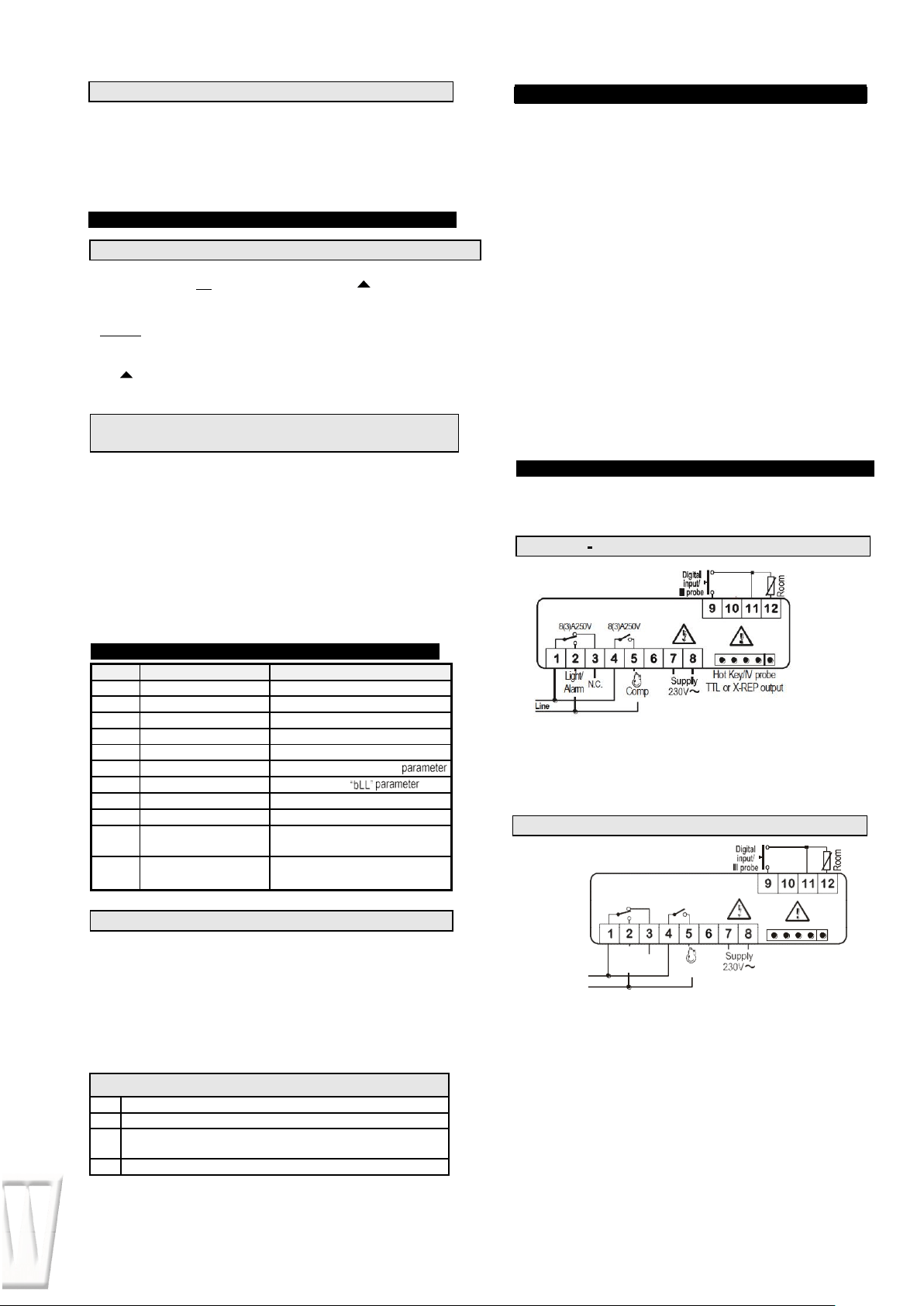
The X-REP output excludes the TTL output. It´s present in the following codes:
XR30CH- xx2xx, XR30CH – xx3xx.
9-40Vdc supply: connect to the terminals 7 and 8.
12Vac/dc supply: connect to the terminals 7 and 8.
24Vac/dc supply: connect to the terminals 7 and 8.
120Vac supply: connect to the terminals 7 and 8.
14.2 OTHER MESSAGES
Pon Keyboard unlocked.
PoF
Keyboard locked
noP
In programming mode: none parameter is present in Pr1
On the display or in dP2, dP3, dP4: the selected probe is nor enabled
noA None alarm is recorded.
16.1 XR30CH 8A COMPRESSOR
8(3)A250V
20(8)A250V
Light/
N.C
.
Alarm
Comp
Hot
Key/IV
probe
TTL or X-REP output
Line
16
.
CONNECTIONS
15
. TECHNICAL DATA
13.2 HOW TO PROGRAM AN INSTRUMENT
USING A HOT KEY (DOWNLOAD)
13
.
HOW TO USE TH
E HOT KEY
13.1 HOW TO PROGRAM A HOT KEY FROM THE INSTRUMENT (UPLOAD)
12.1 PROBE CONNECTION
14.1 ALARM RECOVERY
9
-
40Vdc
supply
: connect to the terminals 7 and
8.
12Vac/dc supply: connect to the terminals 7 and 8.
24Vac/dc supply: connect to the terminals 7 and 8.
120Vac supply: connect to the terminals 7 and 8.
16.2 XR30CH – 20A COMPRESSOR
Loading ...
Loading ...
Loading ...