Loading ...
Loading ...
Loading ...
User Instructions Ultra Low Temperature Freezers Model LAB
Side 8 | 14
CONDENSER TEMPERATURE ALARM (detected by the fourth probe)
AP2 Probe selection for temperature alarm of condenser: nP = no probe;
P1 =thermostat probe; P2 = evaporator probe; P3 =configurable probe; P4 =
Probe on Hot Key plug.
AL2 Low temperature alarm of condenser: (-55÷150°C) when this temperature is
reached the LA2 alarm is signalled, possibly after the Ad2 delay.
Au2 High temperature alarm of condenser: (-55÷150°C) when this temperature is
reached the HA2 alarm is signalled, possibly after the Ad2 delay.
AH2 Differential for temperature condenser alarm recovery: (0,1÷25,5°C; 1÷45°F)
Ad2 Condenser temperature alarm delay: (0÷255 min) time interval between the
detection of the condenser alarm condition and alarm signalling.
dA2 Condenser temperature alarm exclusion at start up: (from 0.0 min to
23.5h, res.10min)
bLL Compressor off with low temperature alarm of condenser: n = no:
compressor keeps on working; Y = yes, compressor is switched off till the
alarm is present, in any case regulation restarts after AC time at minimum.
AC2 Compressor off with high temperature alarm of condenser: n = no:
compressor keeps on working; Y = yes, compressor is switched off till the
alarm is present, in any case regulation restarts after AC time at minimum.
SECOND RELAY
tbA Alarm relay silencing (with oA1=ALr):
(n= silencing disabled: alarm relay stays on till alarm condition lasts,
y =silencing enabled: alarm relay is switched OFF by pressing a key during
an alarm).
oA1 Second relay configuration: ALr: alarm; Lig: light; AuS: Auxiliary relay;
onF: always on with instrument on; db = do not select it; dEF:
do not select it!.; FAn: do not select it!.; dF2: do not select it.
AoP Alarm relay polarity: it set if the alarm relay is open or closed when an alarm
happens. CL= terminals 1-2 closed during an alarm;
oP = terminals 1-2 open during an alarm
i1P Digital input polarity: oP: the digital input is activated by opening the
contact; CL: the digital input is activated by closing the contact.
i1F Digital input configuration: EAL = external alarm: “EA” message is displayed;
bAL = serious alarm “CA” message is displayed. PAL
pressure switch alarm, “CA” message is displayed; dor = door
switch function; dEF = activation of a defrost cycle; AUS =to
switch on the second relay if oA1 = Htr = kind of action
inversion (cooling – heating); FAn = not set it;
did: (0¸255 min) with i1F= EAL or i1F = bAL digital input alarm delay: delay
between the detection of the external alarm condition and its signalling.
with i1F= dor: door open signalling delay
with i1F = PAL: time for pressure switch function: time interval to calculate
the number of the pressure switch activation.
nPS Pressure switch number: (0 ÷15) Number of activation of the pressure switch,
during the “did” interval before signaling the alarm event.(12F = PAL)
If the nPS activation in the did time is reached, switch off and on the instrument
to restart normal regulation.
odc Compressor status with door open: no, Fan = normal; CPr;
F_C = Compressor OFF.
rrd Outputs restart after doA alarm: no = outputs not affected by the doA alarm;
yES = outputs restart with the doA alarm;
HES Temperature increase during the Energy Saving cycle it sets the increasing
value of the set point during the Energy Saving cycle
Adr Serial address (1÷244): Identifies the instrument address when connected to a
ModBUS compatible monitoring system.
PbC Type of probe: it allows to set the kind of probe used by the instrument: PbC = PBC
probe, ntc = NTC probe.
onF on/off key enabling: nu = disabled; oFF = enabled; ES = not set it.
dP1 Thermostat probe display
dP3 Third probe display- optional.
dP4 Fourth probe display.
rSE Real set point: (readable only), it shows the set point used during the energy saving
cycle or during the continuous cycle.
rEL Software release for internal use.
Ptb Parameter table code: readable only.
8. DIGITAL INPUT (ENABLED WITH P3P = N)
The free voltage digital input is programmable in different configurations by the “i1F”
parameter.
It signals the door status and the corresponding relay output status through
the “odc” parameter: no, Fan = normal (any change); CPr, F_C = Compressor OFF.
Since the door is opened, after the delay time set through parameter “did”, the door
alarm is enabled, the display shows the message “dA” and the regulation restarts
is rtr = yES. The alarm stops as soon as the external digital input is disabled again.
With the door open, the high and low temperature alarms are disabled.
As soon as the digital input is activated the unit will wait for “did” time delay before
signaling the “EAL” alarm message. The outputs status don´t change. The alarm
stops just after the digital input is de-activated.
When the digital input is activated, the unit will wait for “did” time delay before
signaling the “CA” alarm message. The relay outputs are switched OFF. The alarm
will stop as soon as the digital input is de-activated.
If during the interval time set by “did” parameter, the pressure switch has reached
the number of activation of the “nPS” parameter, the “CA” pressure alarm
message will be displayed. The compressor and the regulation are stopped. When
the digital input is ON the compressor is always OFF.
If the nPS activation in the did time is reached, switch off and on the
instrument to restart normal regulation.
It starts a defrost if there are the right conditions. After the defrost is finished, the
normal regulation will restart only if the digital input is disabled otherwise the
instrument will wait until the “MdF” safety time is expired.
This function allows to invert the regulation of the controller: from cooling to
heating and viceversa.
The Energy Saving function allows to change the set point value as the result of
the SET+HES (parameter) sum. This function is enabled until the digital input is
activated.
The digital input polarity depends on the “i1P” parameter.
i1P=CL: the input is activated by closing the contact.
i1P=OP: the input is activated by opening the contact
The TTL serial line, available through the HOT KEY connector, allows by means of
the external TTL/RS485 converter, XJ485-CX, to connect the instrument to a
monitoring system ModBUS-RTU compatible such as the X-WEB500/3000/300.
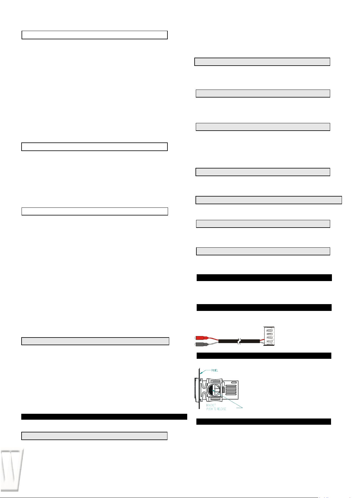
As optional, an X-REP can be connected to the instrument, trough the HOT KEY
connector. The X-REP output EXCLUDES the serial connection.
To connect the X-REP to
the instrument the following
connectors must be used
CAB-51F(1m) CAB-
52F(2m), CAB- 55F(5m)
Instrument XR30CH shall be mounted on
vertical panel, in a 29x71 mm hole, and fixed
using the special bracket supplied. The
temperature range allowed for correct
operation is 0÷60 ˚C. Avoid places subject to
strong vibrations, corrosive gases, excessive
dirt or humidity. The same recommendations
apply to probes. Let air circulate by the
cooling holes.
The instrument is provided with screw terminal block to connect cables with a
cross section up to 2,5 mm². Before connecting cables make sure the
power supply complies with the instrument`s requirements. Separate the
probe cables from the power supply cables, from the outputs and the power
connections. Do not exceed the maximum current allowed on each relay, in
case of heavier loads use a suitable external relay.
12
.
ELECTRICAL CONNECTIONS
11. INSTALLATION
AND MOUNTING
9. TTL SERIAL LINE FOR MONITORING
SYSTEMS
DIGITAL INPUT
8.1 DOOR SWITCH INPUT (i1F = dor)
8.2 GENERIC ALARM (i1F = EAL)
8.3 SERIOUS ALARM MODE (i1F = bAL)
8.4 PRESSURE SWITCH (i1F = PAL)
8.5 START DEFROST (i1F = dFr)
8.6 INVERSION OF THE KIND OF ACTION: HEATING-COOLING (i1F = Htr)
8.7 ENERGY SAVING (i1F = ES)
8.8 DIGITAL INPUTS POLARITY
10. X
-
REP
OUTPUT
OPTIONAL
OTHER
Loading ...
Loading ...
Loading ...