Loading ...
Loading ...
3
• If used, a 208/230-volt wall receptacle must be located
within 58 inches of the lower right sleeve corner. Exten-
sion cords must not be used with the unit. See the note
on Figure 1.
• For installations in walls deeper than 13-7/8 inches,
special care is necessary to prevent problems with rain
water, condensate drainage and intake/discharge air.
Under these circumstances, careful job site analysis
and precautions are required. You must consult with
your Sales Representative and receive approval before
attempting such installations.
OUTDOOR ENCLOSURE PANEL REMOVAL
The sleeve stiffener must be taken out before the enclosure
panel can be removed from the sleeve.
1. Remove the zig-zag folded cardboard sleeve stiffener (Fig-
ure 7).
Sleeve
Stiffener
Figure 7- Sleeve Stiffener Removal
2. Remove the rear closure panel by folding the four flaps as
indicated in Figure 8.
Rear Closure
Panel
Flaps
Figure 8 - Rear Enclosure Panel
3. Grasping the top and bottom flanges of the rear closure
panel as shown in Figure 9, the entire panel is pulled out
diagonally from one side.
Figure 9 - Panel Removal
Install the wall sleeve condenser air grille by using the screws
and holes provided. (See the Installation Instructions pro-
vided for the grille kits.)
PRE-INSTALLATION CONSIDERATIONS
Before proceeding with the sleeve installation, ensure the
following guidelines for locating the wall opening and sleeve
are met:
• The wall opening must be the correct size. See Figure 1
for wall sleeve dimensions and Figure 2 for minimum
wall opening size.
• The wall sleeve will need to be installed with minimum
clearances to the floor and adjacent walls. Minimum
projections of the sleeve into and out of the room will
also have to be met. See Figures 3 and 4 as well as Table
1 for details.
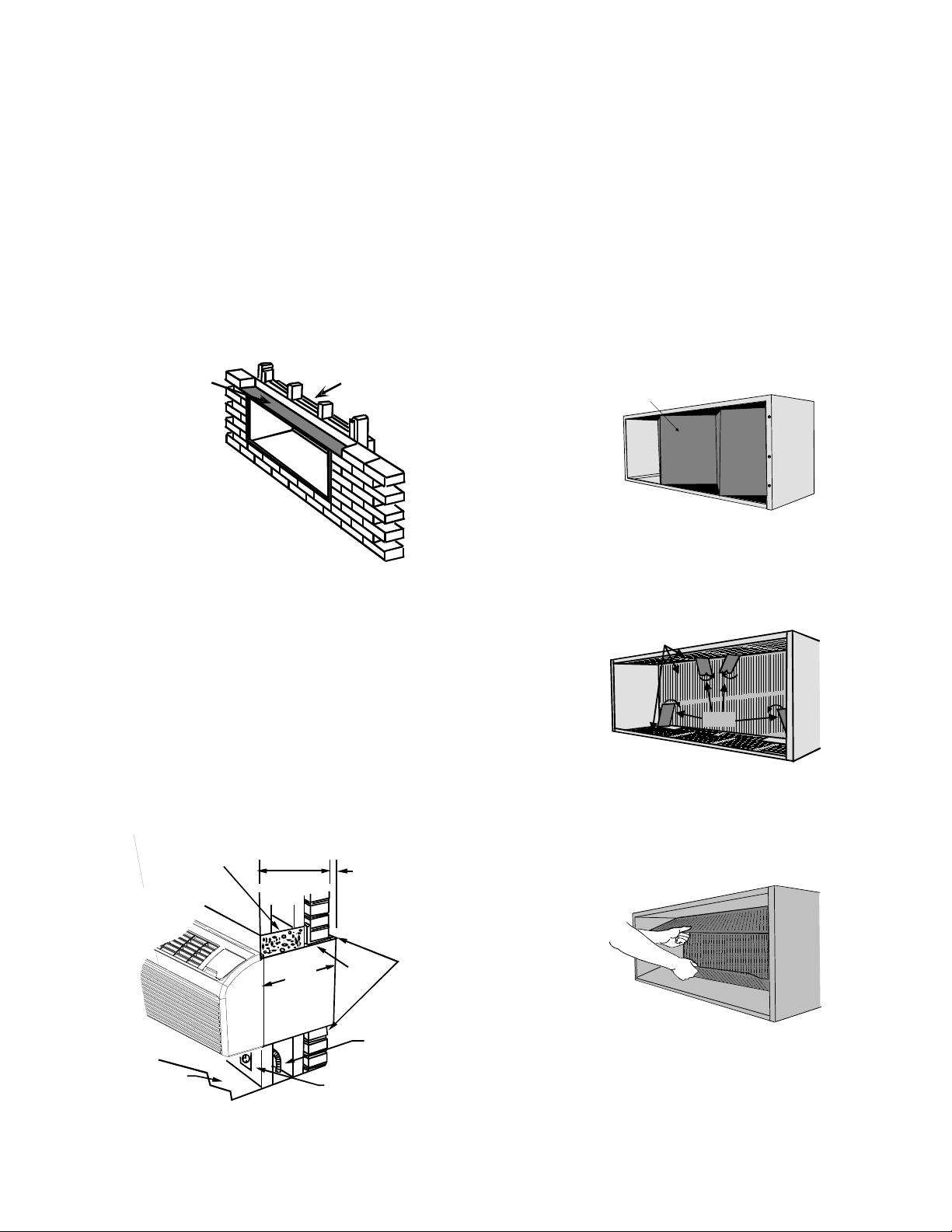
• If installed in a concrete or masonry wall, a lintel must
be provided in the wall opening for support. Do not use
the wall sleeve as a lintel. See Figure 5 for a typical
lintel construction.
Wood
Frame
Lintel
Figure 5 - Framing with Lintel
• When installed in the opening, the wall sleeve must be
horizontally level from side to side and pitched (one
quarter bubble in the sight glass) to the outside. DO
NOT SLOPE THE WALL SLEEVE TOWARD THE ROOM.
(Figure 5)
• The installer must determine and supply the mounting
bolts and/or screws to attach the wall sleeve to the
sides of the wall opening. Make sure the wall opening is
adequate for strong support.
• The installer must provide adequate sealing and insula-
tion around the sleeve after it is installed. See Figure 6
for one of many types of constructions.
Steel
Lintel
Caulk Top,
Bottom, and
Both Sides
1/4"
6 mm
Minimum
Projection
Concrete
Lintel
Power Supply
Conduit
Receptacle
Finished
Floor
13 1/2" (340 mm)
Maximum
(No Accessories)
13 3/4"
350 mm
Figure 6 - Block and Brick Veneer Installation
Loading ...