Loading ...
2
1
6
1
/
1
6
"
4
1
0
m
m
Wall Receptacle Within 58" From
Bottom Right Side Corner on
208/230 VAC Units Only
4
2
"
1
0
6
5
m
m
1
4
1
/
8
"
3
5
9
m
m
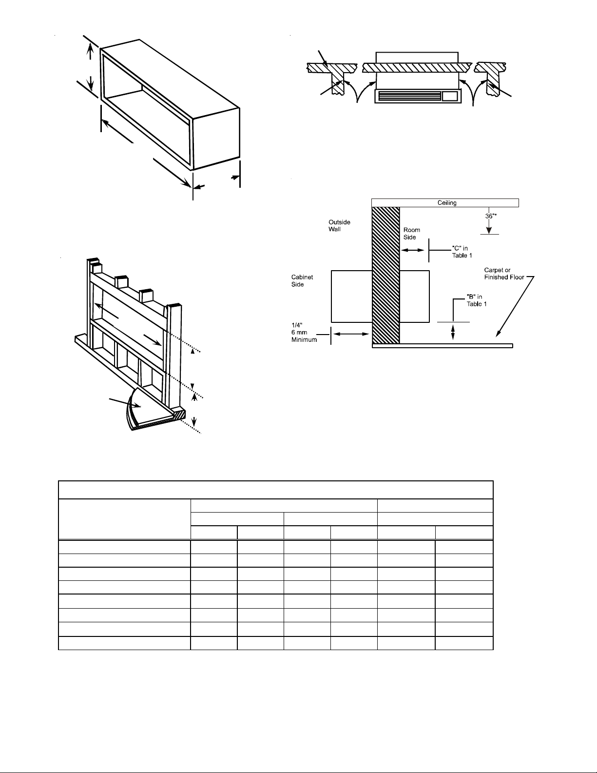
Figure 1 - Wall Sleeve Dimensions
4
2
1
/
4
"
1
0
7
5
m
m
M
i
n
i
m
u
m
1
6
1
/
4
"
4
1
5
m
m
M
i
n
i
m
u
m
Finished Floor
Dimension "B"
in Table 1
Figure 2 - Minimum Wall Opening Dimensions
1
If inside mounted then B = 1 1/2 inches (40 mm)
2
To achieve a flush fit between the hydronic front and the finished wall, Dimension “C” must be between 3” and 3 1/8”. If this dimension is more than
3 1/8” there will be a gap between the front and the wall. This gap could permit occupant access to hydronic lines or other dangerous parts. For flush
mounts, internal drain kits or flashing are required to prevent leaking from external drains into space. See drain kit installation for details on sleeve
positioning for internal drain kits.
3
This dimension can be from 0” to 3-1/4”, but cannot exceed 3-1/4”. If this dimension exceeds 3-1/4”, the skirt around the front will not reach the floor.
Table 1
Top of Wall Sleeve
"A"
Minimum
"A"
Minimum
Internal
Adjacent
Wall
Internal
Adjacent
Wall
Outside
Wall
Allow Front Clearance (See Table 1)
Figure 3 - Minimum Unit Clearances
* To ensure proper airflow and filter removal, it is recommended
the wall sleeve be installed a minimum of 36” from the ceiling.
Figure 4 - Minimum Interior and Exterior
NOTE: To ensure proper airflow and filter removal, it is recom-
mended installation of the wall sleeve be a minimum of 36” from
the ceiling.
Inches mm Inches mm Inches mm
Wall Sleeve Only 3 75 0 0 0 0
Subbase Kit 3 75 3 1/4 85 2 3/4 70
Leveling Legs Kit 3 75 3 75 2 50
Duct Kit 3 75 0 0 2 3/8 35
Hydronic Heat Kit "A Series" 9 230 0 to 3 1/4
3
0 to 85
3
3
2
75
2
Hydronic Heat Kit "J Series" 6 150 0 0 2 1/2 65
Drain Kit 3 75 '0
1
'0
1
00
Hardwire Kit 3 75 1 1/4 30 0 0
OPTION
MINIMUM CLEARANCES AND PROJECTIONS
MINIMUM CLEARANCES MINIMUM PROJECTION
C (Figure 4)B (Figure 3)A (Figure 2)
Loading ...
Loading ...