5151 San Felipe, Suite 500 • Houston, TX 77056 • www.amana-ptac.com
© 1996, 2000, 2004-2005, 2017 Goodman Company, L.P.
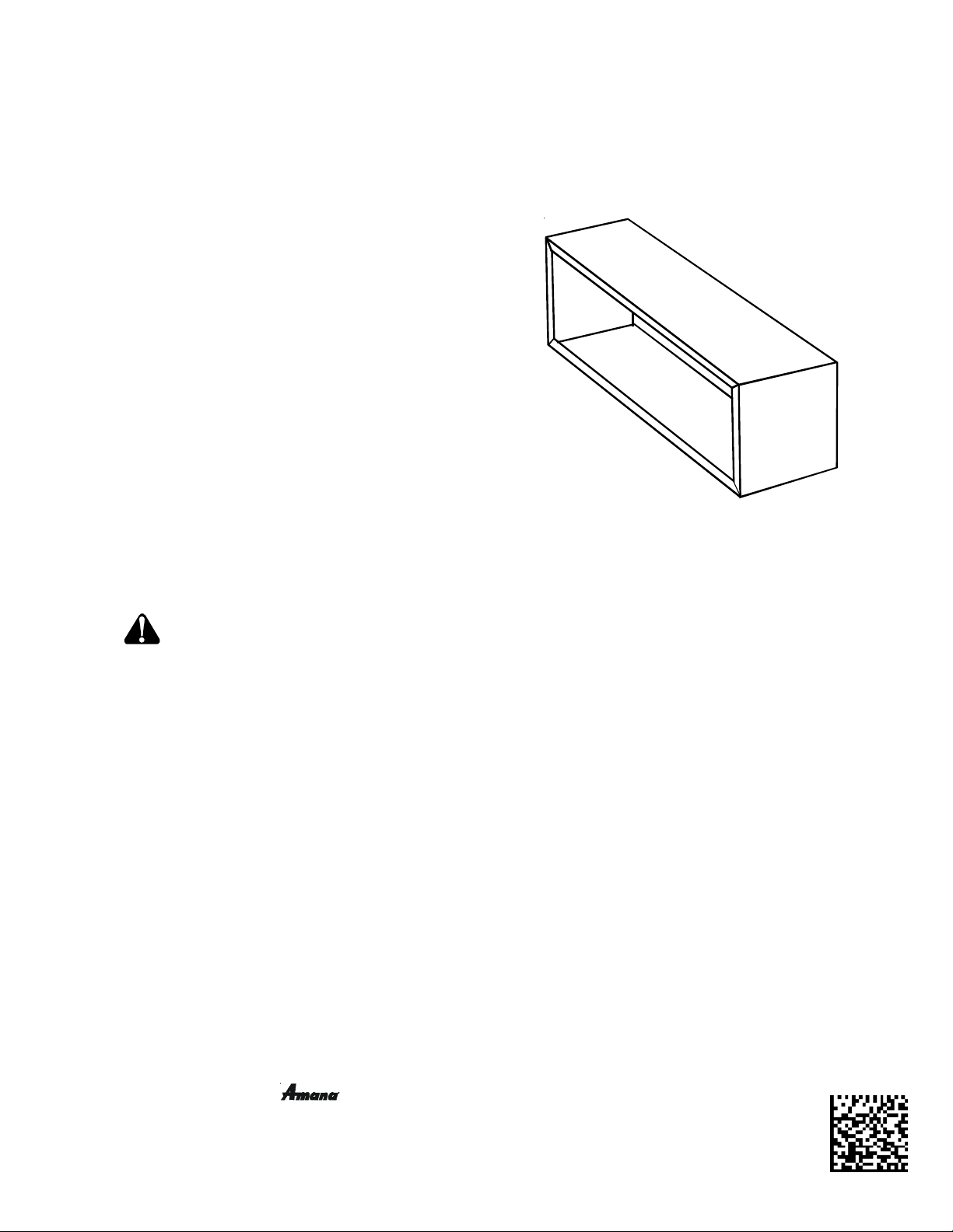
The wall sleeve must be installed before the air conditioner or heat pump chassis can be set in place.
Read the instructions thoroughly before proceeding.
INDEX
ATTENTION INSTALLING PERSONNEL ................................... 1
KIT ACCESSORIES ................................................................. 1
DRAIN KIT ..................................................................... 1
SUBBASE, LEVELING LEGS, MAIN DUCT & HYDRONIC HEAT KITS ........ 1
PRE-INSTALLATION CONSIDERATIONS.................................. 3
OUTDOOR ENCLOSURE PANEL REMOVAL ................................... 3
WALL SLEEVE INSTALLATION ............................................... 4
PTAC
W
ALL
S
LEEVE
INSTALLATION INSTRUCTIONS
ATTENTION INSTALLING PERSONNEL
As a professional installer you have an obligation to know the
product better than the customer. This includes all safety
precautions and related items.
Prior to actual installation, thoroughly familiarize yourself
with this Instruction Manual. Pay special attention to all
safety warnings. Often during installation or repair it is pos-
sible to place yourself in a position which is more hazardous
than when the unit is in operation.
Remember, it is your responsibility to install the product
safely and to know it well enough to be able to instruct a
customer in its safe use.
Safety is a matter of common sense...a matter of thinking
before acting. Most dealers have a list of specific good safety
practices...follow them.
The precautions listed in this Installation Manual are intended
as supplemental to existing practices. However, if there is a
direct conflict between existing practices and the content of
this manual, the precautions listed here take precedence.
RECOGNIZE THIS SYMBOL AS A SAFETY
PRECAUTIONDESCRIPTON
When 230/208 volt units are to be installed, the power supply
may be either cord connected or permanent wiring. Perma-
nent wiring may be done through the hard wire junction box,
or the accessory subbase.
When 265 volt units are to be installed, the power supply
must be permanent wiring. Permanent wiring may be done
through the accessory hard wire junction box, or the acces-
sory subbase. An exposed cord connection on 265 volt units
is not permitted.
The subbase accessory includes leveling legs. If added wall
sleeve support is required and the subbase is not to be used
an accessory leveling leg kit may be installed.
is a registered trademark of Maytag Corporation or its related companies and is used under license to
Goodman Company, L.P., Houston, TX, USA. All rights reserved.
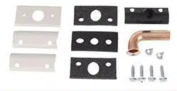
KIT ACCESSORIES
DRAIN KIT
An indoor/outdoor drain kit is available as an accessory item.
When a drain kit is to be installed, do so before installing the
wall sleeve in the wall. See the drain kit for actual installation
instructions.
SUBBASE, LEVELING LEGS, MAIN DUCT, AND HYDRONIC HEAT
KITS
Installation of these kits requires drilling of mounting holes on
both sides of the wall sleeve. The minimum required clearance
distance between the wall sleeve and wall is shown in Table 1.
If the distance between wall sleeve and wall will be at or near
the minimum clearance distance, mount these kits on the
sleeve before installing the sleeve in the wall. The kit installa-
tion instructions are included with the accessory kits.
A3495105r4
01 / 2017
2
1
6
1
/
1
6
"
4
1
0
m
m
Wall Receptacle Within 58" From
Bottom Right Side Corner on
208/230 VAC Units Only
4
2
"
1
0
6
5
m
m
1
4
1
/
8
"
3
5
9
m
m
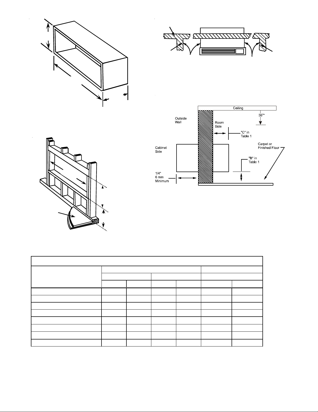
Figure 1 - Wall Sleeve Dimensions
4
2
1
/
4
"
1
0
7
5
m
m
M
i
n
i
m
u
m
1
6
1
/
4
"
4
1
5
m
m
M
i
n
i
m
u
m
Finished Floor
Dimension "B"
in Table 1
Figure 2 - Minimum Wall Opening Dimensions
1
If inside mounted then B = 1 1/2 inches (40 mm)
2
To achieve a flush fit between the hydronic front and the finished wall, Dimension “C” must be between 3” and 3 1/8”. If this dimension is more than
3 1/8” there will be a gap between the front and the wall. This gap could permit occupant access to hydronic lines or other dangerous parts. For flush
mounts, internal drain kits or flashing are required to prevent leaking from external drains into space. See drain kit installation for details on sleeve
positioning for internal drain kits.
3
This dimension can be from 0” to 3-1/4”, but cannot exceed 3-1/4”. If this dimension exceeds 3-1/4”, the skirt around the front will not reach the floor.
Table 1
Top of Wall Sleeve
"A"
Minimum
"A"
Minimum
Internal
Adjacent
Wall
Internal
Adjacent
Wall
Outside
Wall
Allow Front Clearance (See Table 1)
Figure 3 - Minimum Unit Clearances
* To ensure proper airflow and filter removal, it is recommended
the wall sleeve be installed a minimum of 36” from the ceiling.
Figure 4 - Minimum Interior and Exterior
NOTE: To ensure proper airflow and filter removal, it is recom-
mended installation of the wall sleeve be a minimum of 36” from
the ceiling.
Inches mm Inches mm Inches mm
Wall Sleeve Only 3 75 0 0 0 0
Subbase Kit 3 75 3 1/4 85 2 3/4 70
Leveling Legs Kit 3 75 3 75 2 50
Duct Kit 3 75 0 0 2 3/8 35
Hydronic Heat Kit "A Series" 9 230 0 to 3 1/4
3
0 to 85
3
3
2
75
2
Hydronic Heat Kit "J Series" 6 150 0 0 2 1/2 65
Drain Kit 3 75 '0
1
'0
1
00
Hardwire Kit 3 75 1 1/4 30 0 0
OPTION
MINIMUM CLEARANCES AND PROJECTIONS
MINIMUM CLEARANCES MINIMUM PROJECTION
C (Figure 4)B (Figure 3)A (Figure 2)
3
• If used, a 208/230-volt wall receptacle must be located
within 58 inches of the lower right sleeve corner. Exten-
sion cords must not be used with the unit. See the note
on Figure 1.
• For installations in walls deeper than 13-7/8 inches,
special care is necessary to prevent problems with rain
water, condensate drainage and intake/discharge air.
Under these circumstances, careful job site analysis
and precautions are required. You must consult with
your Sales Representative and receive approval before
attempting such installations.
OUTDOOR ENCLOSURE PANEL REMOVAL
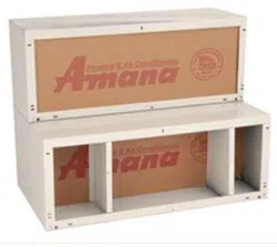
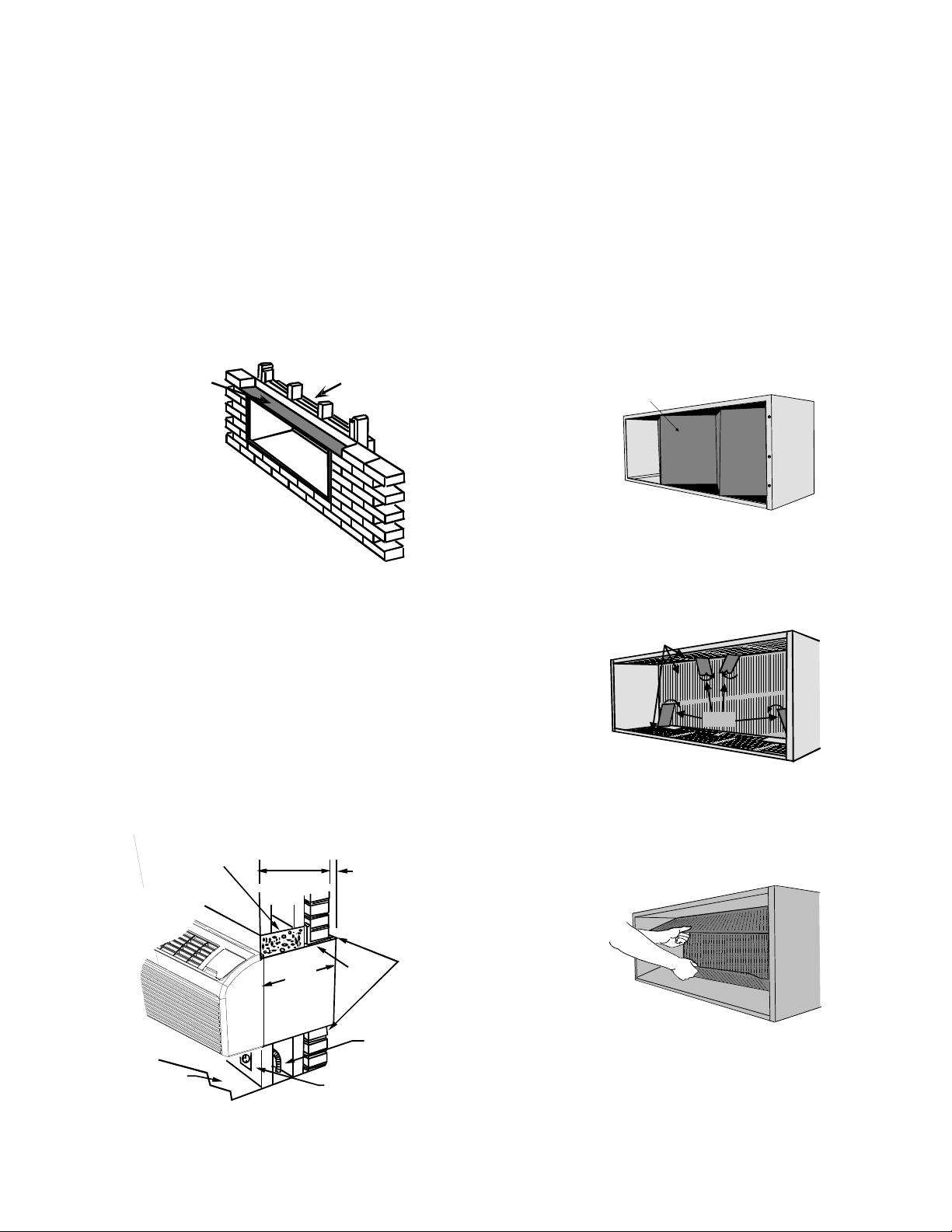
The sleeve stiffener must be taken out before the enclosure
panel can be removed from the sleeve.
1. Remove the zig-zag folded cardboard sleeve stiffener (Fig-
ure 7).
Sleeve
Stiffener
Figure 7- Sleeve Stiffener Removal
2. Remove the rear closure panel by folding the four flaps as
indicated in Figure 8.
Rear Closure
Panel
Flaps
Figure 8 - Rear Enclosure Panel
3. Grasping the top and bottom flanges of the rear closure
panel as shown in Figure 9, the entire panel is pulled out
diagonally from one side.
Figure 9 - Panel Removal
Install the wall sleeve condenser air grille by using the screws
and holes provided. (See the Installation Instructions pro-
vided for the grille kits.)
PRE-INSTALLATION CONSIDERATIONS
Before proceeding with the sleeve installation, ensure the
following guidelines for locating the wall opening and sleeve
are met:
• The wall opening must be the correct size. See Figure 1
for wall sleeve dimensions and Figure 2 for minimum
wall opening size.
• The wall sleeve will need to be installed with minimum
clearances to the floor and adjacent walls. Minimum
projections of the sleeve into and out of the room will
also have to be met. See Figures 3 and 4 as well as Table
1 for details.
• If installed in a concrete or masonry wall, a lintel must
be provided in the wall opening for support. Do not use
the wall sleeve as a lintel. See Figure 5 for a typical
lintel construction.
Wood
Frame
Lintel
Figure 5 - Framing with Lintel
• When installed in the opening, the wall sleeve must be
horizontally level from side to side and pitched (one
quarter bubble in the sight glass) to the outside. DO
NOT SLOPE THE WALL SLEEVE TOWARD THE ROOM.
(Figure 5)
• The installer must determine and supply the mounting
bolts and/or screws to attach the wall sleeve to the
sides of the wall opening. Make sure the wall opening is
adequate for strong support.
• The installer must provide adequate sealing and insula-
tion around the sleeve after it is installed. See Figure 6
for one of many types of constructions.
Steel
Lintel
Caulk Top,
Bottom, and
Both Sides
1/4"
6 mm
Minimum
Projection
Concrete
Lintel
Power Supply
Conduit
Receptacle
Finished
Floor
13 1/2" (340 mm)
Maximum
(No Accessories)
13 3/4"
350 mm
Figure 6 - Block and Brick Veneer Installation
4
WALL SLEEVE INSTALLATION
After the wall opening is checked and approved for location,
size, and clearances, complete the following to install the wall
sleeve.
1. Remove the outside enclosure panel from the wall sleeve.
2. Slide the wall sleeve into the wall opening. Do not distort
the cabinet shape to fit the wall opening; the unit chassis
must fit snugly and uniformly into the wall sleeve.
3. Locate the sleeve within the range of minimum projec-
tions, as shown in Figures 3 and 4, so both sides are at
least the minimum projection from the wall.
4. Check the level of the wall sleeve. For proper drainage,
the sleeve should be level from side to side and one-quar-
ter bubble in the sight glass sloping to the outside.
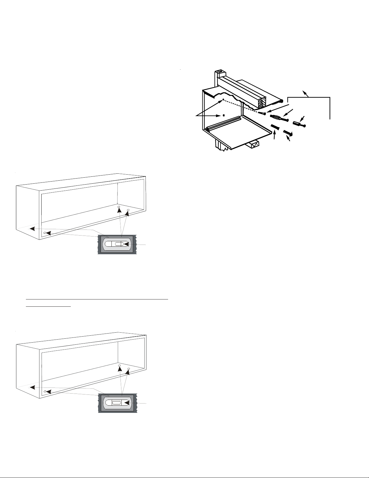
See Figure 10 for proper location to check wall sleeve with
level. The level should show a 1/4 bubble slope to the
outside.
Place level on dimples in wall sleeves’ corners.
For proper placement, level should show 1/4 bubble slope to the outside
in both the left and right hand corners.
1/4 bubble
slope to
the outside
Figure 10 - Checking Wall Sleeve for 1/4 Bubble Slope
NOTE: If using an internal drain kit, the sleeve must be level
from front to back.
See Figure 11 for proper location to check wall sleeve with
level. The sleeve should be level from side to side.
Place level on dimples or next to the dimples in wall sleeves’ corners.
For proper placement, sleeve should be level from front to back
in both the left and right hand corners.
Level from
side to
to side
Figure 11-Checking Wall Sleeve for Level
5. Two holes will need to be drilled in both sides of the wall
sleeve for mounting into the wall. Drill holes of proper size
and in the proper location so the screws will engage into
strong supporting members of the wall. DO NOT DRILL
THROUGH BOTTOM OF SLEEVE. Figure 12 shows possible
fastening methods.
Mounting
Holes
(Drilled by
Installer)
Plastic
Anchor
Screws
Expansion
Anchor Bolt
Toggle Bolt
Wood Screw
Alternative
Fastening Method
(Field Supplied)
Figure 12 - Wall Sleeve Attachment to Opening
6. Check the level of the wall sleeve and adjust if necessary.
7. Caulk or seal around the outside of the entire sleeve.
8. If the unit chassis will not be installed immediately, re-
place the enclosure panel on the outside opening of the
sleeve. This will prevent weather damage to the building
interior.
9. Recycle or dispose of packaging materials per local codes.