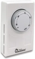
WALL THERMOSTAT
Model: DR-001
READ CAREFULLY - These instructions will help prevent difficul-
ties that might arise during thermostat installation.Studying the instruc-
tions first may save considerable time and money later.Observing the
following procedures will keep installation time to a minimum.Save these
instructions for future use.
READ ALL WIRE SIZING, VOLTAGE RE-
QUIREMENTS AND SAFETY DATA TO
AVOID PROPERTY DAMAGE AND PER-
SONAL INJURY OR ELECTRIC SHOCK.
READ AND SAVE THESE INSTRUCTIONS
L1 from
Supply Panel
L2 from
Supply Panel
L1
Thermostat
Wire Connector
Heater
LOAD
L
OAD
L
2
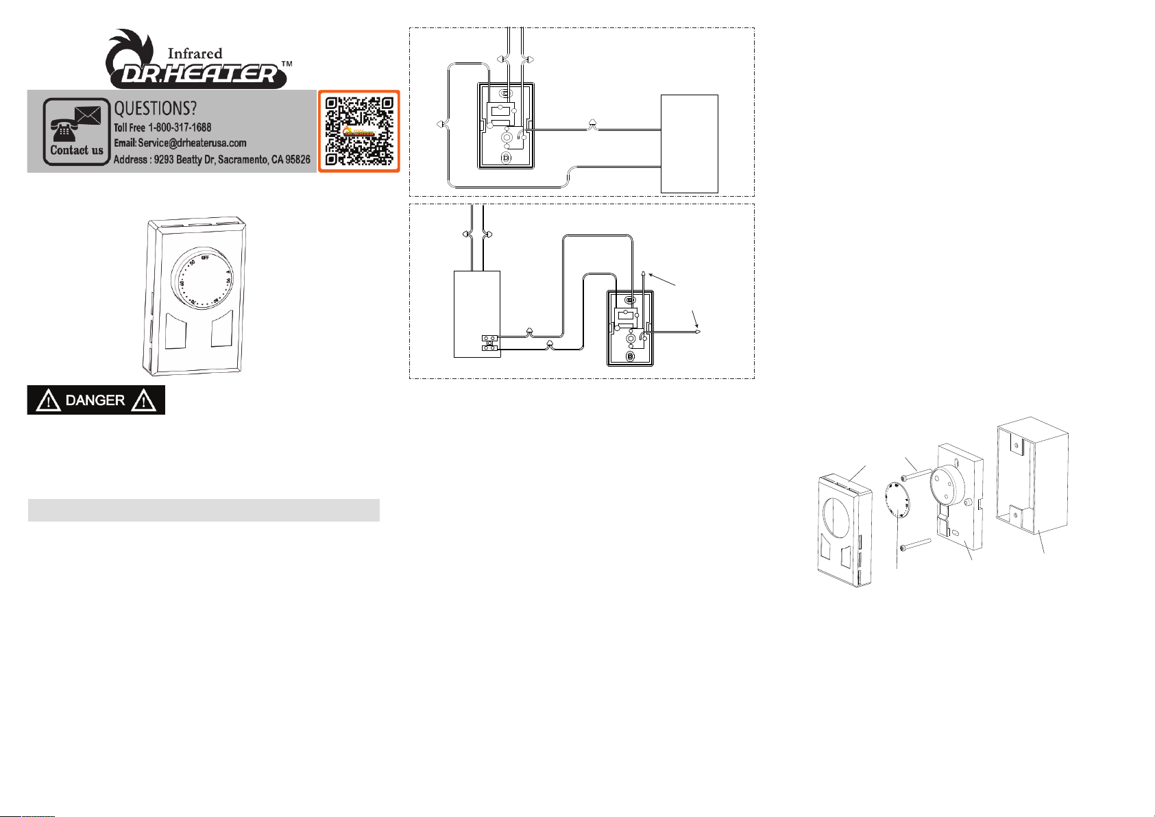
Direct Load and Contactor Control
Thermostat Installation
1. Disconnect power supply to prevent electrical shock or damage
to product before installation. Recommend opening the Main
breaker from power panel to disconnect power.
2. Run line voltage wires to the thermostat location.
3. The connection for Direct Load Control (DLC) is :
***Connection from thermostat to the heating unit:
a) Connect one BLACK load wire from the thermostat to one
of the line wire from the heating unit.
b) Connect the other BLACK load wire from the thermostat to
the other line wire from the heating unit
***Connection from the thermostat to the supply panel:
a) Connect the RED line wire from the thermostat (L1) to L1
line from the supply panel.
b) Connect the other RED line wire from the thermostat (L2)
to L2 line from the supply panel.
4. The connection for Contactor Control is :
a) Use two 16AWG wires (not included) to Terminal A inside the
heater. (See example in diagram.)
b) Connect one RED line wire from the thermostat to one 16AWG
line wire from the Termimal A. Then connect the BLACK load wire
from the thermostat to the other 16AWG line wire from the
Termimal A.
c) The other line wires from the thermostat shuld be affixed with
insulating tape.
5. Make sure all connections are secured, and no exposed wiring.
6. Insert wires into the junction box, make sure not to damage
wiring.
7. Secure the ground wire to the ground screw provide in junction
box.
8. Remove the thermostat cover by grabbing the cover from the
sides and pull it away from the base.
9. Mount the thermostat into the junction box and secure using the
provided screws.
10. Replace thermostat cover.
The installation of the thermostat must comply with the applicable local
and/or national electrical code and utility requirements. This installation
should be performed by a qualified electrician where required by law.
Ensure that all wiring connections to the thermostat are correct and tight
to prevent electrical shorts. Use the appropriate wire to meet local and
national electrical codes for rated power consumption
.
Product Setup and Settings
To adjust the temperature to your requirements, turn the dial on the
thermostat clockwise all the way to turn heater on. When the room
reaches the desired temperature, turn the thermostat knob counter
clockwise until you hear the click. Leave in this position to maintain
the room temperature at this setting. For additional heat, turn clock-
wise until you hear the click and the heater will turn on.
Specifications:
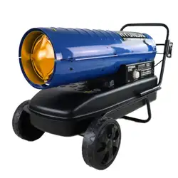
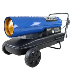
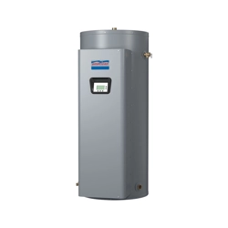
Thermostat is compatible with electric heaters and electric garage
heaters
Power Supply AC 120V / 208V / 240V / 277V Maximum Power:
3360W @ 120VAC (28A)
5824W @ 208VAC (28A)
6720W @ 240VAC (28A)
7756W @ 277VAC (28A)
Sensing Element: Bimetal Temperature Operating Range:
41°F-90°F (5°C -32°C)
cETLus listing.
Functions And Features
• 120/208/240/277 Volts
•Includes both ºC and ºF control dials
•Wall mount design– Sits flush against wall
•Double terminals – provides positive OFF position
•Disconnects power for extra protection
•Large knob allows easy adjustment to all temperatures
•90°F (32°C) maximum setting
Installation Instructions
Cover
Screw
Index Plate
Base
Outlet Box
(Not Included
)
Warning: Turn OFF the power at the circuit breaker before in-
stalling. Installation should be performed by a qualified electrician.
Refer to thermostat and heater load specifications before installa-
tion of the thermostat to see if it can handle the amp load. The max-
imum this thermostat can run is 7756 Watts at 277 Volts, 6720
Watts at 240 Volts, 5824 Watts at 208 Volts and 3360 Watts at 120
Volts.
Install unit in a grounded metal or plastic wall junction box, indoors
4 ½’ to 5’ above the floor. Avoid any area where it can come in to
contact with external sources of heat and cold. This includes plumb-
ing pipes, direct sunlight, a T.V. set, lamps, and drafts from a door
or window, as this may cause inaccurate temperature readings. The
most convenient place is above the light switch. Not for outdoor
use.
For Direct Load
Control Only
- Turning knob fully counter clockwise will disconnect the power to
the heater.
Changing °C and °F control dials.
Use a small flathead screwdriver to pry off the control dial. Insert into
one of the slots on the dial and gentle apply pressure to remove.To
install the new control dial, line up the pins on the dial with the holes
on the thermostat knob. Push together until secured into place.
L1
Thermostat
W
ire Connector
Heater
LOAD
LOAD
L2
Affixed with
insulating tape
Black
Red
Terminal A
L1 from
S
upply Panel
L2 from
S
upply Panel
L1
L2
Red
Black
For Contactor
Control