
®
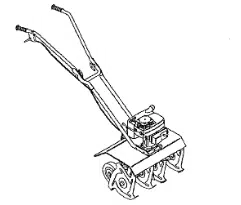
32.8 cc 2-cycle
10 inch Diameter Tines
MiNi TILLER/CULTIVATOR
MODEL NO.
536.797501
Caution:
Read and follow all Safety
Rules and Operating
Instructions before first use
of this product.
SEARS, ROEBUCK AND CO., Hoffman Estates 60179 U.S.A.
339426 03/07/96
Table of Contents 2 Service and Adjustments 13_i4
Warranty 2 Storage 14-15
Safety Rules 2-3 Troubleshooting 15
Contents of Shipping Carton 4 Edger Repair Parts 16-19
Assembly 4-6 Engine Repair Parts 20-23
Operation 7-10 Spanish (EspaSol) 24-39
Maintenance t1-12 Parts Ordering/Service. Back Cover
LIMITED ONE-YEAR WARRANTY ON CRAFTSMAN
MINI TILLER/CULTIVATOR
Foroneyearfromthedateofpurchase,whenthisCraftsmanMinitiller/cultivatoris
maintained,lubricated,andtunedupaccordingtotheoperatingandmaintenancein-
structionsintheowner'smanual,Searswillrepair,freeofcharge,anydefectin mate-
rialorworkmanship_
Thiswarrantyexcludestine(s),sparkplug,andaircleanerwhichareexpendableparts
and becomewornduringnormaluse.
If thisMinitiller/cultivatorisusedfor commemialorrentalpurposes,thiswarrantyap-
pliesforonly30 daysfrom thedateofpurchase.Thiswarrantyappliesonlywhilethis
productisinusetheUnitedStates,WARRANTYSERVICEISAVAILABLEBYRE*
TURNINGTHE MINI TILLER/CULTIVATORTO THE NEARESTSEARSSERVICE
CENTERtNTHE UNITEDSTATES..
Thiswarrantygivesyouspecificlegalrights,andyoumayalsohaveotherrightswhich
varyfrom statetostate.
SEARS,ROEBUCKANDCO.,D617WA,HoffmanEstates,IL60179
Lookfor thtssymbolto pointout Importantsafety precautions.It means--
ATTENTION!!!Become alert!!!YoursafetyIs involved.
Z_ CAUTION: Always disconnect spark
plug wire and place wire where it cannot
contactspark plugto prevent accidental
startingwhen setting-up, transporting,
adjusting or making repairs,
IMPORTANT: Safety standards require
operator presence controlsto minimize the
risk of injury.Your mini tUlerlcuitivatoris
equipped with such controls,Do not attempt
to defeat the function of the operator
presence control under any circumstances,
BEFORE USE
. Read the owner's manual carefully. Be
thoroughlyfamiliar with the controlsand
the proper use of the mini tiller/cultivator.
Know how to stop the mini tiller/cultivator
and disengage the controls quickly.
. Do not operate the mini tiller/cultivator
without wearing adequate outer gar-
ments. Wear footwear that will improve
footingon slippery surfaces=
- Keep the area of operation clear of all
persons, particularly small children and
pets.
• Thoroughly inspect the area where the
mini tiller/cultivator is to be used and
remove all foreign objects.
FUEL SAFETY
• Handle fuel withcare; itis highly flam-
mable.
• Use an approved container.
• Check fuel supply before each use,
allowing space for expansion as the heat
of the engine and/or sun can cause fuel to
expand_
• Fitl fuel tank outdoors with extreme care,
Never fill fuel tank indoors, Replace fuel
tank cap securely and wipe up spilled
fuel.
Never remove the fuel tank cap or add
fuel to a running or hot engine.
Never store fuel or mini tiller/cultivatora
2
with fuel in the tank inside a building
where fumes may reach an open flame.
OPERATING SAFETY
. Never allow children or young teenagers
to operate the mini tillertcultivatoro Keep
them away while it is operating, Never
allow adults to operate the mini tiller/
cultivatorwithoutproper instruction,
• Do not operate this machine if you are
taking drugs or other medication which
can cause drowsiness or affect your
ability to operate this machine.
• Do not use this machine ifyou are
mentally or physically unable to operate
this machine safely.
• Always wear safety glasses or eye
shields during operation or while perform-
ing an adjustment or repair to protect
your eyes from foreign obiects that may
be thrown from the mini tiUer/cuttivator
• Do not put hands or feet near or under
rotatingparts.
• Exercise extreme caution when operating
on or crossing gravel drives, walks, or
roads_ Stay alert for hidden hazards or
traffic,
• Exercise caution to avoid slipping or
falling.
• Never operate the mini tiller/cultivator
without proper guards, piates, or other
safety protective devices in place,
• Never operate the mini tiller/cultivator at
high transport speeds on slippery
surfaces, Look behind and use care when
backing.
• Never altow bystanders near the mini
tiller/cultivator,
• Keep children and pets away while
operating,
• Never operate the mini tiller/cultivator
without good visibility or light.
• Do not run the engine indoors The
exhaust fumes are dangerous, containing
CARBON MONOXIDE, an ODORLESS
and DEADLY GAS.
- Take a!} possible precautions when
leaving the mini tiller/cultivatorunat-
tended. Stop the engine,
• Do not overload the mini tiilertcultivator
capacity by attempting to till too deep at
too fast a rate.
SAFE STORAGE
• Always refer to the owner's manual
instructions for important details ifthe mini
tillertcultivator is to be stored for an
extended period.
• Never store the mini tillerlcultivator with
fuel in the fuel tank inside a building
where ignition sources are present such
as water and space heaters, clothes
dryers, and the like. Allow the engine to
cool before storing in any enclosure°
• Keep the mini tiller/cultivator in safe
working condition° Check eli fasteners at
frequent intervals for proper tightness.
REPAIR]ADJUSTMENTS SAFETY
• After striking a foreign object, stop the
engine (motor). Remove the wire from the
spark plug, and keep the wire away from
the plug to prevent accidental starting,
Thoroughly inspect the mini tilter/cultivator
for any damage, and repair the damage
before restartingand operating it.
• If mini tiller/cultivator shouldstart to
vibrate abnormally, stop engine (motor)
and check immediately for the cause,
Vibration is generally a warning of trouble.
. Stop the engine (motor) whenever you
leave the operating position, Also,
disconnect the spark plug wire before
unclogging the tines and when making
any repairs, adjustments, or inspections
• When cleaning, repairing, or inspecting,
shut off the engine and make certain all
moving parts have stopped°
• Never attempt to make any adjustments
while the engine is running except when
specilically recommended by the manu-
facturer.
L_ WARNING: The engine exhaust
from this product contains chemicals
known to the State of Californiato cause
cancer, birth defects or other reproductive
harm.
Z_ WARNING: This unit isequipped
with an internalcombustion engine and
should not be used on or near any unim-
proved forest-covered, brush-covered or
grass-covered land unless the engine's ex-
haust system is equipped with a spark at-
rester meeting applicable Iocal or state laws
(if any)° ff a spark arrester is used, itshould
be maintained in effective working orderby
the operator.
3
in the state of California the spark attester is
required by law (Section 4442 of the CafifoP
nia Public Resources Code), Other states
may have similar laws, Federat laws apply
onfederallands.Asparkarrester/muffleris
availablethroughyournearestSearsAutho-
rizedServiceCenter(See REPAIRPARTS
sectioninthismanual),
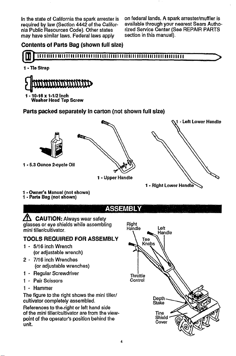
Contents of Parts Bag (shown full size)
1-Tie Strap
1 -10-16x 1-1/2Inch
WasherHead TapScrew
Parts packed separately In carton (not shown full size)
1 - 5.3 Ounce2-cycle Oil
1 - Upper Handle
1- Owner's Manual(not shown)
1 -Parts Bag(not shown)
•Lett Lower Handle
Z_ CAUTION: Always wear safety
glasses or eye shields while assembling
mini tiller/cultivator,,
TOOLS REQUIRED FOR ASSEMBLY
1 * 5/16 inch Wrench
(oradjustable wrench)
2 - 7/16 inch Wrenches
(or adjustable wrenches)
t - Regular Screwdriver
1 - Pair Scissors
1 - Hammer
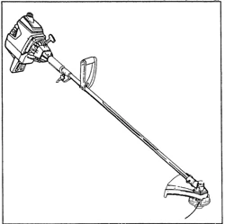
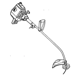
The figure tothe righ! showsthe minitiller/
cultivatorcompletely assembled,
References to the,right or left hand side
ofthe mini tiller/cultivatorare from the view-
pointofthe operator's positionbehind the
unit.
Right
Handle Left
Stake
Tine ,'_"-_.-,-,-,-,-,-,-,-_
Shield""_('<:_3_
Cover _,_
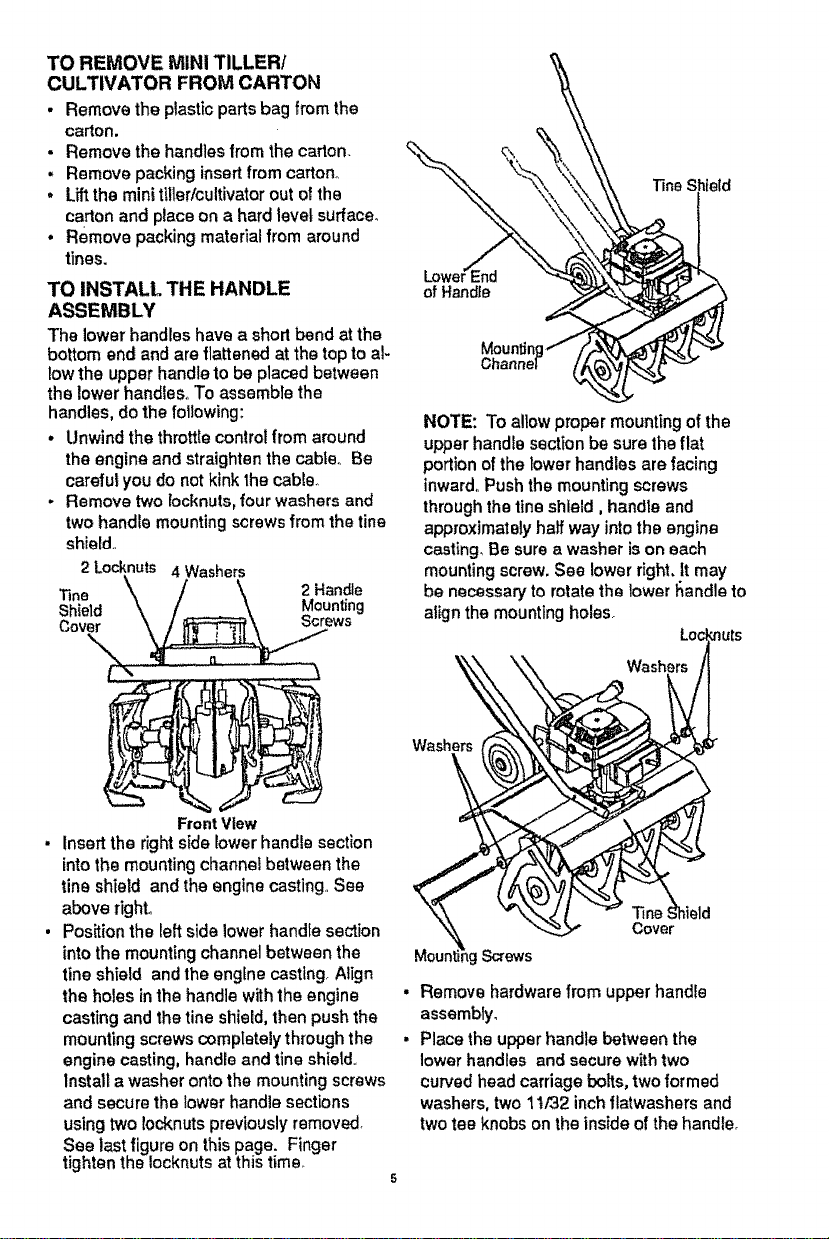
TO REMOVE MINI TILLER/
CULTIVATOR FROM CARTON
• Remove the plastic parts bag from the
carton.
• Remove the handles from the carton.
- Remove packing insert from carton°
* Lift the mini tillerlcultivator out of the
_arton and place on a hard level surface.
. Remove packing material from around
tines.
TO INSTALL THE HANDLE
ASSEMBLY
The lower handles have a short bend at the
bottom end and are flattened at the top to al-
low the upper handle to be placed between
the lower handlesoTo assemble the
handles, do the following:
. Unwind the throttle controlfrom around
the engine and straighten the cabte_ Be
careful you do not kink 1hecable,,
- Remove two [ocknuts,four washers and
two handle mountingscrews from the tine
shield,,
2 Locknuts 4 Washers
line 2 Handle
Shie|d Mounting
Cover Screws
of Handle
Moun
NOTE: To allow proper mounting of the
upper handle section be sure the flat
portion of the lower handles are facing
inward. Push the mounting screws
through the tlne shield, handle and
approximately haft way into the engine
casting, Be sure awasher is on each
mounting screw, See lower right,It may
be necessary to rotate the lower handle to
align the mounting holes_
FrontView
Insertthe rightside lower handle section
intothe mounting channel between the
line shield and the engine casting,,See
above right.
Position the left side lower handle section
into the mounting channel between the
fine shield and the engine casting° Align
the holes in the handle with the engine
casting and the tine shield, then push the
mounting screws completelythrough the
engine casting, handle and line shield.,
Install a washer onto the mounting screws
and secure the lower handle sections
using two locknuts previously removed
See last figure on this page. Finger
tighten the Iocknuts at this time,
5
Washers
Cover
Screws
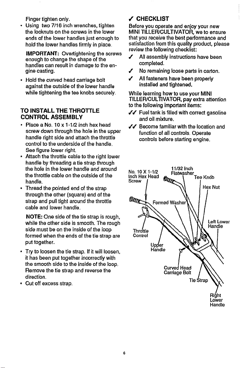
• Remove hardware from upper handie
assembly.
• Place the upper handle between the
lower handles and secure with two
curved head carriage belts, two formed
washers, two 11/32 inch flatwashers and
two tee knobs on the inside of the handle°
Fingertightenonly.
° Using two 7/16 inch wrenches, tighten
the Iocknuts on the screws in the lower
ends of the lower handles just enough to
hold the lower handles firmly in place
IMPORTANt; Overtighteningthescrews
enough tochangetheshapeofthe
handlescanresultindamagetotheen-
ginecasting.
• Hold the curved head carriage bolt
against the outside of the lower handle
while tightening the tee knobs securely.
TO INSTALL THE THROTTLE
CONTROL ASSEMBLY
• Place a Nov 10 x 1-1/2 inchhex head
screw down through the holein the upper
handle right side and attachthe throttle
control to the underside of the handle.
See figure Iower right.
• Attach the throttle cable to the right lower
handle by threadinga tie strap through
the hole in the lower handle and around
the throttlecable on the outside of the
handle.
• Thread the pointed end of the strap
through the other (square) end of the
strap and pull tight around the throttle
cable and lower handle,
NOTE; One sideof thetiestrap isrough,
whiletheothersideis smooth.The rough
sidemustbeontheinsideoftheloop
formed whentheendsofthetiestrapare
puttogether.
• Try to loosen the tie strap_ If it willloosen,
it has been put together incorrectly with
the smooth side to the inside of the loop
Remove the tie strap and reverse the
direction°
• Cut off excess strap,
/ CHECKLIST
Before you operate and enjoy your new
MINI TILLER/CULTIVATOR, we to ensure
that you receive the best performance and
satisfactionfrom this quality product, please
review the following checklist:
/ All assembly instructionshave been
completed.
/ No remaining looseparts in carton.
All fasteners have been properly
installedand tightened,
WhilelearninghowtouseyourMINI
TILLER/CULTIVATOR,payextraattention
tothefollowingimportantitems:
/4' Fueltankisfilled withcorrectgasoline
andoilmixture°
/4' Becomefami!_arwiththelocation and
functionofallcontrols_Operate
controlsbeforestartingengine.
11/32Inch
No.10X t-1t2 Flatwasher
_-_\_ Hex Nut
Car ageBolt
3"ie_ ,rap _fk \
P& r
Handle
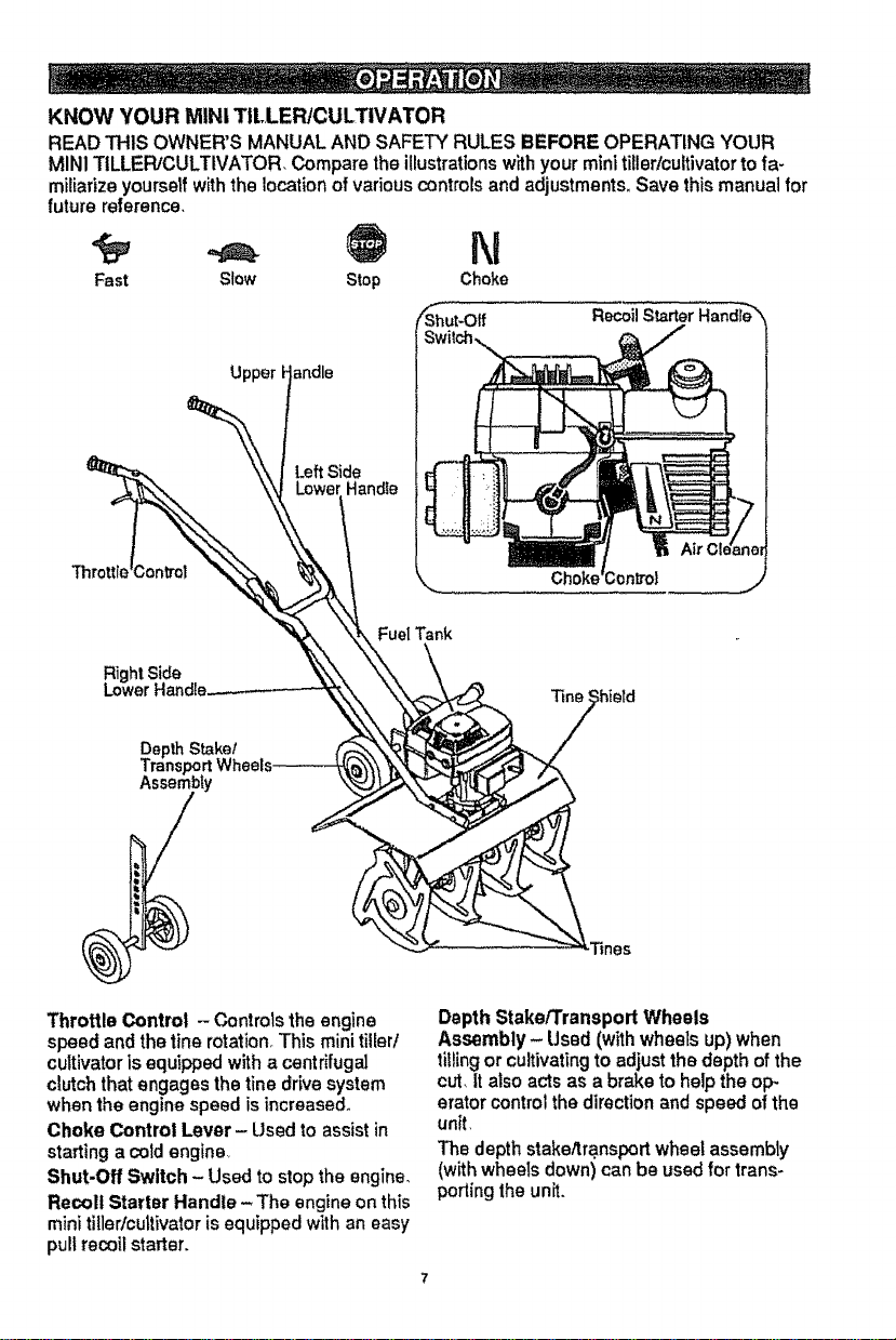
KNOW YOUR MINI TILLER/CULTIVATOR
READTHIS OWNER'SMANUALANDSAFETYRULESBEFOREOPERATINGYOUR
MINITILLER/CULTIVATOR,Comparetheillustrationswithyourminitiller!cultivatortofa_
miiiarizeyourseffwiththelocationofvariouscontrolsandadjustments.Savethismanualfor
future reference,
Fast Stew Stop
N
Choke
SfShut-Otf
RecoilStarterI-
Throttle Control -Controts the engine
speed and the fine rotation,This mini tiller/
cultivatoris equipped with a centrifugal
clutchthat engages the tine drive system
when the engine speed is increased.
Choke Control Lever - Used to assist in
starting a cold engine,
Shut-Off Switch - Used to stop the engine.
Recoil Starter Handle - The engine on this
minitiller/cultivatorisequipped with an easy
pull recoil starter.
Depth Stake/Transport Wheels
Assembly- Used (withwheels up)when
tiifing or cultivatingto adjust the depth of the
cut, It also acts as a brake to help the op-
erator controlthe direction and speed of the
unit,
The depth stake/transport wheel assembly
(with wheels down) can be used for trans-
porting the unit.
HOW TO USE YOUR TILLER/
CULTIVATOR
.A
/_ WARNING: The operation ofthis
mini tiller/cultivatorcan result inforeign ob-
jects being thrown into the eyes, which can
cause severe eye damage. Always wear
safety glasses or eye shields while operat*
ing the minitiller/cultivator.
We recommend standard safety glasses or
Wide Vision Safety Mask for over your
glasses.
TO STOP MINI TILLER]CULTIVATOR
• Release the throttle controlto stopthe
tines.
• Move the shut-off switchon the engine to
the OFF position.
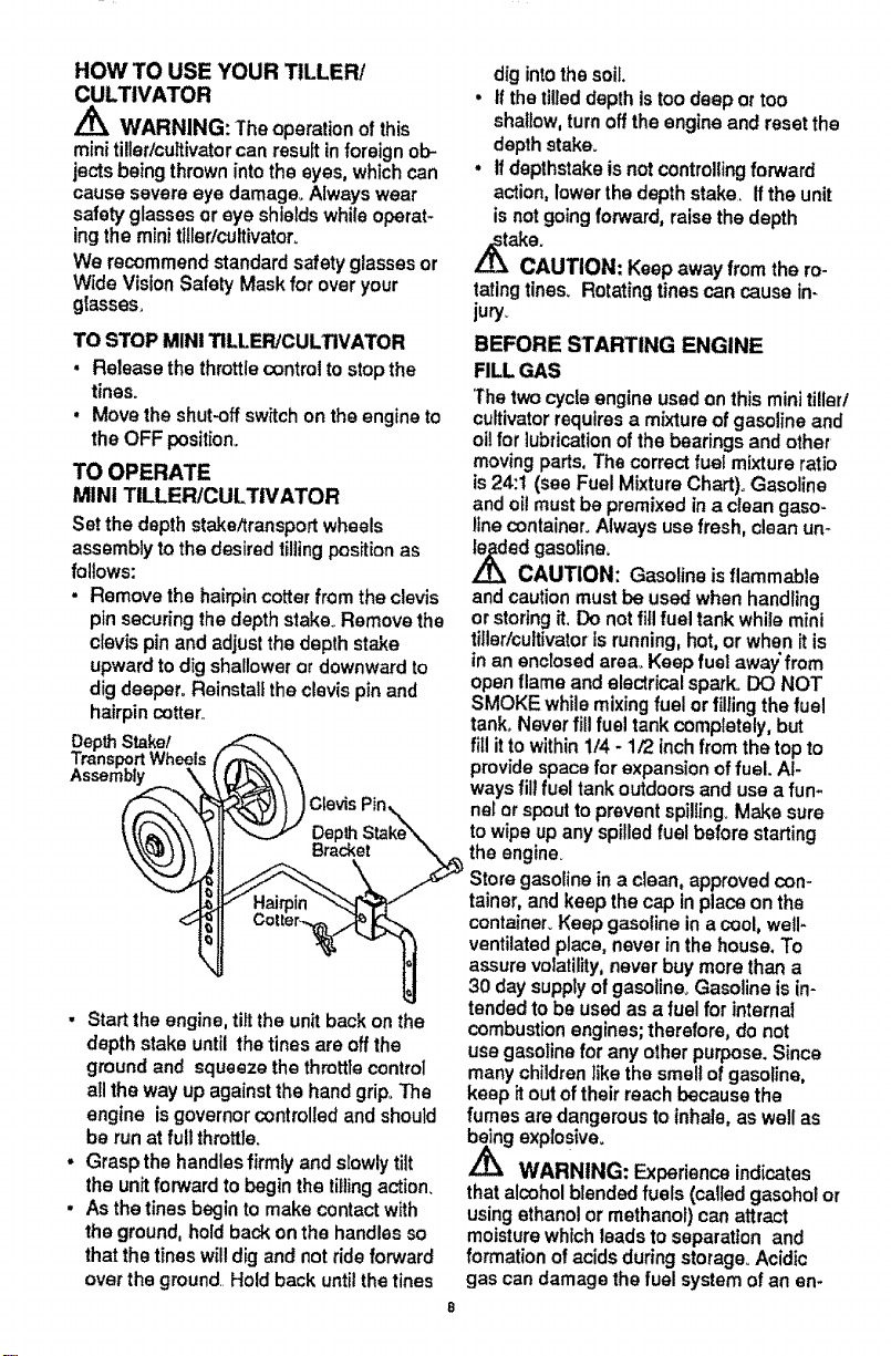
TO OPERATE
MINi TILLER/CULTIVATOR
Set the depth stake/transport wheels
assembly to the desired tillingpositionas
follows:
. Remove the hairpincotter from the clevis
pin securing the depth stake_Remove the
clevis pin and adjust the depth stake
upwardtodig shallower or downward to
dig deeper° Reinstall the clevis pin and
hairpincotter..
DepthStake/
Transl_rt Wheels
Assembly
Clevis
, Start the engine, tiltthe unit back on the
depth stake until the tines are off the
ground and squeeze the throttle control
allthe way up against the hand grip. The
engine is governor controlledand should
be run at full throttle.
• Grasp the handles firmly and slowly tilt
the unit forward to begin the tillingaction.
• As the tines begin to make contact with
the ground, hold back on the handles so
that the tines willdig and not ride forward
over the ground. Hold back until the tines
dig intothe soil,
• if the ttlled depth istoo deep or too
shallow,turn off the engine and reset the
depth stake_
, tf depthstake is not controllingforward
action, lower the depth stake. If the unit
is not goingforward, raise the depth
,_ake.
CAUTION: Keep away from the ro-
tatingtines. Rotating tines can cause in-
jury_
BEFORE STARTING ENGINE
FILL GAS
'Thetwo cycle engine used on this mini tiller/
cultivatorrequires a mixture ofgasoline and
oil for lubrication of the bearings and other
moving parts, The correct fuel mixture ratio
is24:1 (see Fuel Mixture Chart). Gasoline
and oil must be premixed in a clean gaso-
line container. Always use fresh, clean un-
ed gasoline.
CAUTION: Gasoline is flammable
and caution must be used when handling
or storing it. Do not fill fuel tank while mini
tiller/cultivatorisrunning, hot, or when it is
in an enclosed area_Keep fuel away'from
open flame and electrical spark. DO NOT
SMOKE while mixingfuel or filling the fuel
tank_Never fill fuel tank completely, but
fill itto within !/4 - 1/2 inchfrom the top to
provide space for expansion of fuel. Al-
ways fill fuel tank outdoors and use a fun-
nel or spoutto prevent spilling. Make sure
to wipe up any spilled fuel before starting
the engine.
gasolinein a clean, approved con-
tainer, and keep the cap in place on the
containeh Keep gasoline in acool, welF
ventilated place, never in the house. To
assure volatility,neverbuy more than a
30 day supplyofgasotine_Gasoline isin-
tended to be used as a fuel for internal
combustion engines;therefore, do not
use gasoline for any other purpose. Since
many children like the smell of gasoline,
keep itout of their reach because the
fumes are dangerous to inhale, as well as
._g explosive.
WARNING: Experience indicates
that alcohol blended fuels (called gasohol or
using ethanolor methanol) can attract
moisture which leads to separation and
formation of acids during storage. Acidic
gas can damage the fuel system of an en-
gine while in storage° To avoid engine prob-
lems, the fuel system should be emptied
before storage for 30 days or Ionger. Drain
the gas tank, startthe engine and let it run
until the fuel lines and carburetor are empty.
Use fresh fuel next season. See Storage
Instructions for additional information,
Never use engine or carburetor cleaner
products in the fuel tank or permanent dam-
age may occur.
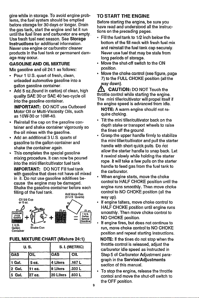
GASOUNE AND OIL MIXTURE
Mix gasoline and oi!24:1 as follows:
- Pour 1 U.S. quart of fresh, clean,
unleaded automotive gasoline into a
gallon gasoline container,
- Add 5 oz.(found in carton) of clean, high
quality SAE 30 or SAE 40 two-cycle oil
intothe gasoline container.
IMPORTANT: DO NOT use Outboard
Motor Oil or Muitt-Vfscosity Oils, such
as 10W-30 or 10W-40o
• Reinstall the cap on the gasoline con-
tainer and shake container vigorously so
the oil mixes withthe gasoline.
, Add an additional 3 U.S..quarts of
gasoline to the gallon container and
shake the container again..
• Thiscompletes the special gasoline
mixing procedure. It can now be poured
into the mini tillerlcultivator fuel tank.
IMPORTANT: DO NOT Fill fuel tank
with gasoline that does not have oil mixed
in it. Do not use gasoline additives be-
cause the engine may be damaged..
Shake the gasoline container before each
fillingof the fuel tank, AddMoreGas
(3U,S Quarts)
O_ 5/8 Cup
OF 5 oz,
I U,S,
Gallon Shake Can
Container
;UELMIXTURECHART(Mixture24:1)
U,S°
GAS DIL
1Gal. i5 oz.
2 Gal. 11 oz.
5 GBI, 27oz.
SoI.(METRIC)
GAS OIL
4 Uters .167 L
8 Ulers .333 L
20 Liters ,833 L
TO START THE ENGINE
Before starting the engine, be sure you
have read and understood all the instruc-
tions on the preceding pages.
• Fill the fueltank to 1/2 inch belowthe
bottom of the fill neck with fresh fuel mix
and reinstallthe fuel tank cap securely,.
Never use fue! that may be stale from
long periods of storage°
• Move the shut.off switch to the ON
position°
• Move the choke control (see figure, page
7) to the FULL CHOKE position (all the
/_ay down)..
CAUTION." DO NOT Touch the
throttle controlwhile starting the engine,
The mini tillerlcultivator willpropel itself if
the engine speed is advanced from idleo
NOTE: A warm engine should not re-
quire choking.
• Tiltthe minl tiller/cultivatorback on the
depth stake or transportwheels to raise
the tinesoff the ground.
• Grasp the upper handle firmlyto stabilize
the mini tiller/cultivator and puffthe starter
handle with shortquick pullsoDo r_ot
altowthe starter handle to snap back° Let
it rewindslowlywhile hoidingthe starter
rope, It willtake a few pulison the starter
handle tofeed gas from the fuel tank to
the carburetor.
• When engine starts, move the choke
controlto HALF CHOKE positionuntilthe
engine runs smoothly.Than move choke
controlto NO CHOKE position (atl the
way up)_
° If engine falters, move choke control to
HALF CHOKE position until engine runs
smoothly,. Then move choke control to
NO CHOKE position.
• If engine fires, but does not continue to
run, move choke control to NO CHOKE
position and repeat starting instructions..
NOTE; If the tines do not stop when the
throttlecontrol is released, adjust the
carburetor idle speed as instructed in
Step 5 of CarburetorAdjustment para-
graph in the Sorvlce/Adjustments
section of this manual.
To stop the engine, release the throttle
control and move the shut-off switch to
the OFF position.

- Ifthe engine becomes flooded, see the
Spark Plug Maintenance paragraph in the
Malntenanc_ section of this manual
Then pull the starter rope with the choke
lever in the NO CHOKE position.
CAUTION: The muffler and sur..
roundingareas become hot after running
the engine_ Avoid these areas,
TILLING HINTS
• Tilling is diggingin, turning over and
breaking up packed soil beforeplanting.
Loose unpackedsoil helps rootgrowth.
Best tilling depth is 4 to6 inches. A tiller
will alsoclear the soil of unwanted
vegetation. The decompositionof this
vegetation matter enriches the soil
Depending onthe climate (rainfall and
wind), it may be advisable to tillthe soilat
the end of the growingseason tofurther
conditionthe soil,
. Avoid tillingsoil that istoo dry as itwill
pulverize and produce a dust that willnot
hold water. Also, tillingsoilthat istoo wet
will be hard on the machine and produce
unsatisfactoryclods,
. Better growthwill be obtained intilled
ground ifa relativelysmall area istilled
properly and the tilledground is used
soon after tillingto preserve the moisture
content.
• The depth stake (on the back of the mini
tilter/cultivator)serves a dual purpose
(see figure, page 8) It helps regulate the
depth of the cut to a uniform level and
also acts as a brake to helpthe operator
controlthe speed of the mini tiller/
cultivator,
. Lowering the depth stake willslow the
minitiller/cultivatorand make it tilldeeper..
Raising the depth bar willallow itto move
faster and till more shaliowo
• Ifthe mini tiller!cultivatorstopsfor,Nard
motion and tries to dig deeper than
necessary, move the handles from side to
side to start forward motion.
WEED REMOVAL HINTS
• When using the mint tiller/cultivatorto
remove weeds, it is best totill nodeeper
than t-1/2 Inches° Tillingdeeper willonly
pull tothe surface ungerminatedweed
seeds. You may want toraise the depth
bar to lessen the braking action.
• When tillingaround plantsor close areas,
you may want to remove the outsidetines
(see Tine Replacement paragraph inthe
ServlcelAdjustments section ofthis
manual).
_ CAUTION:
• Read the Owner's manua!.
• Know locationand functions of aU
controls."
• Keep all safety devices and shields in
place,
° Never allow chiidrenor uninstructed
adultsto operate mini tiller/cultivatoro
° Shut off engine before unclogging tines or
making repairs,,
• Keep bystanders away from machine.
° Keep away from rotating parts and tines_
They can cause injury_
PRODUCT SPECIFICATIONS
MODEL NO., 536.797501
DATE PJJDE:
)ATE OF
_URCHASE:
HORSE POWER: t._6HP
)ISPLACEMENT: 2.0 cu. in_
(328 co)
GASOLINE CAPACITY: 20 oz.
FUEL/OIL MIX RATIO: 24:1 Gas To Oil
Use Unleaded Regular) 5 0z. Oil/1 Gal.
Gas)
SPARK PLUG : Champion
(Gap ,035 in,)
RCJ -BY
I0
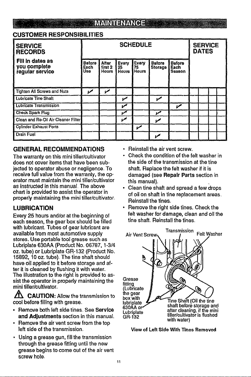
CUSTOMER RESPONSIBILITIES
SERVICE
RECORDS
Fill in datesas
you complete
regularservice
ii
Before After
Each first2
Uso Houm
T{gh_nAll Screws and Nuts p4 v_
Lubflcale Ttne Sha|t tf
Lubr{cate Transmission
r C_ S_k Rug
Cie__d R_-OiiAircie_eiFiiiei
ioy!!o.o,
Drain Fue!
SCHEDULE
_=ry Every Before IBefore
75 Slorago Each
Hours Hours S_son
v' v"
v"
SERVICE
DATES
,, ,,,,.....
GENERAL RECOMMENDATIONS
The warranty on this mini tiller/cultivator
does not cover itemsthat have been sub-
jected to operator abuse or negligence,.To
receive full value from the warranty, the op
erator must maintain the mini tiller/cultivator
as instructedinthis manual, The above
chart is providedto assistthe operator in
properly maintaining the mini ti[ler/cuft{vator_
LUBRICATION
Every 25 hours and!or at the beginning of
each season, the gear box should be _led
with lubricant° Tubes of gear lubricant are
available from most automotive supply
stores, Use portable tool grease such as
Lubriplate 630AA (Product No. 06787, !-3/4
oz, tube) or Lubriplate GR-132 (Product No.
15892, t0 oz. tube),,The tine shaft should
have oil appliedto itbefore storage and af-
ter it iscleaned by flushing it with water.
The illustration to the rightis provided to as-
sist the operator in properly maintain{ng the
mini tiller/cultivator.
CAUTION: Allow the transmissionto
coolbefore fillingwith grease.
• Remove both left side tines_See Servlce
and Adjustments section in this manual
• Remove the air vent screw from the top
left side otthe transmission.
Using a grease gun, fillthe transmission
through the grease fittinguntil the new
grease begins to come out of the air vent
screw hole,
• Reinstall the air vent screw.
- Check the conditionofthe felt washer in
the side of the transmission at the tine
shaft. Replace the felt washer if it is
damaged (see Repair Parts section in
this manual).
• Clean tine shaft and spread a few clrops
of oil on shaft in fine replacement areas,
Reinstall the tines°
• Remove the right side tines. Check the
felt washer for damage, clean and oil the
line shaft, Reinstall the tines.
Transmission
Air VentScrew, FeltWasher
Grease
fitting
(Lub_cate
thegear
boxwith
{Oilthe line
shaftbeforestorageand
Lubriplate aftercleaning,if themini
GRd32 tiller/cultivatorisflushed
withwater)
View of Left Side With Tines Removed
ENGINE
SPARK PLUG MAINTENANCE
if the engine isflooded, clean the area
around the spark plug base to prevent for-
eign matedal from entering the cylinders
when the plug is removed_Remove and dry
the spark plug,.Regap the electrodes to
.035 in, if necessary'. If a new spark plug is
needed, refer to the Product Specifications
chart in this manual forthe proper replace-
mento Tighten the spark plug firmly, if a
torque wrench is available, torque the spark
plug to 15 foot-pounds.
AIR CLEANER MAINTENANCE
The air cleaner fiker should be cleaned and
re-oiled after every 25 hours of use, Clean
more oftenunder dusty conditions.
IMPORTANT: The engine can be worn out
In a very short periodof time ifdirt or gritis
allowed toenter the engine.
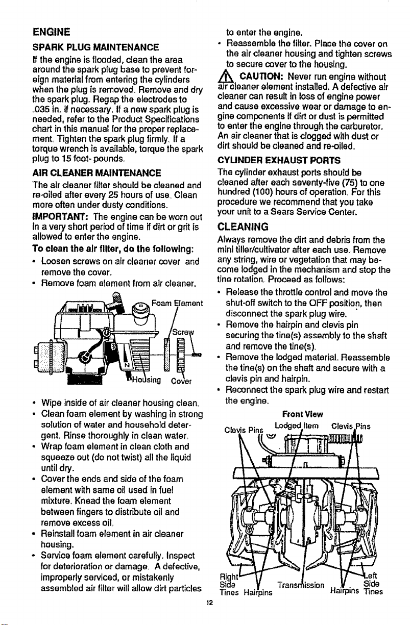
To clean the air filter, do the following:
. Loosen screws on aircleaner cover and
remove the cover_
• Remove foam element from alr cleaner.
nent
• Wipe inside of air cleaner housingclean.
• Clean foam element by washing in strong
solution of water and household deter-
gent. Rinse thoroughly in clean water.
. Wrap foam element in clean cloth and
squeeze out (do not twist) all the liquid
until dry,.
, Cover the ends and side of the foam
element with same oil used in fuel
mixture. Knead the foam etement
between fingers to distribute oil and
remove excess oil
• Reinstall foam element in air cleaner
housing.
. Service foam element carefully. Inspect
for deterioration or damage. A defective,
improperlyserviced, or mistakenly
assembled air filter will allow dirt particles
to enter the engine.
- Reassemble the filter. Place the cover on
the air cleaner housing and tighten screws
tosecure cover tothe housing.
a_rc CAUNON: Never runengine without
leaner element installed.A defective air
cleaner can result in lossof engine power
and cause excessive wear or damage to en-
ginecomponents if dirtor dust is permitted
toenter the engine through the carburetor°
An air cleaner that isclogged withdust or
dirt should be cleaned and re-oiled.
CYUNDER EXHAUST PORTS
The cylinderexhaust ports should be
cleaned after each seventy-five (75) to one
hundred (100) hours of operation, For this
procedure we recommend that you take
your unit to a Sears Service Center.
CLEANING
Always removethe dirt and debris from the
miniti!lerlcultivatorafter each use. Remove
any string,wire or vegetation that may be-
come lodged inthe mechanism and stopthe
tine rotation Proceed as follows:
• Release the throttle controland move the
shut-offswitchto the OFF position,then
disconnect the spark plug wire.
. Remove the hairpin and clevis pin
securing the tine(s) assembly tothe shaft
and remove the tine(s)o
• Remove the lodged material, Reassemble
the tine(s) on the shaft and secure with a
clevis pin and hairpin,,
• Reconnect the spark plug wire and restart
the engine.
Front Vlew
Item Clevis
Right
Side Side
Tines HaiCpJns Tines
12
TINE REPLACEMENT
The mini tillerlcultivatorisleft hand or right
hand as viewed from the operator'sposition
behind the unit.
All four tines on this unitare different and
cannot be interchanged..The tines mustbe
properly installedas shown in figures to the
right or the mini tiller/cultivator will not func-
tion properly,,
For working close around plants or in small
areas, the OLrlsidetines may be removed to
reduce the tilling width to about 7 inches. To
reinstallthe outsidetines see below.
CAUTION: The tinesare sell sharp+
ening and wilt become quite sharp from
use. Handle carefully_
The tines will all wear fairly evenly° ti the
tines are being replaced because ofwear,
we recommend that all four tines be re-
placed at the same time. To replace the
tines, do the following:
. Place the shut-off switch to the OFF
position and disconnect the spark plug
wire.
• Remove the hairpins and the clevis pins
from the tines on one side of the unit and
then remove the tines.,See figure,
previous page+
o Clean the line shaft and oit it at the line
locations.
o Place the inside line on the tine shaft and
reinstallthe clevis pin and hairpin_
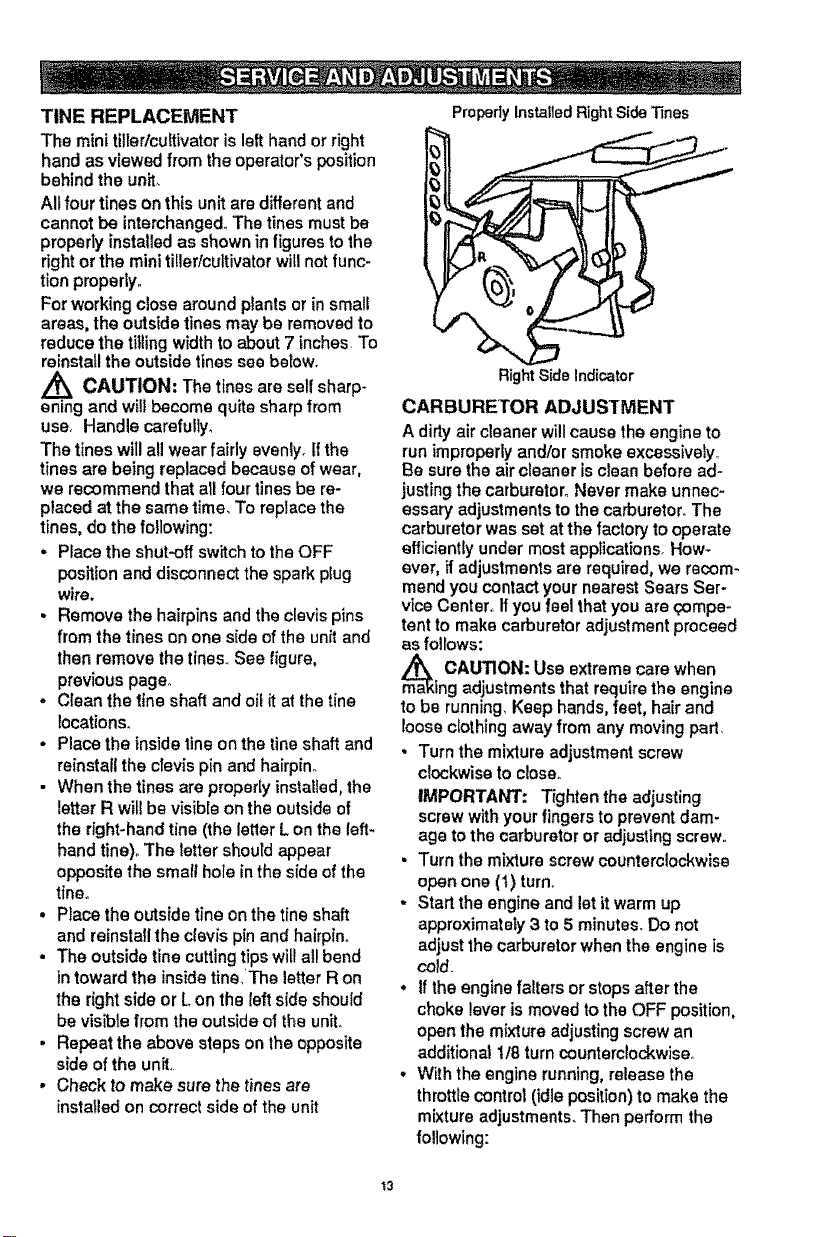
• When the tines are properly installed,the
letterR will be visible on the outside of
the right+handtine (the letter L on the left.
hand tine)_ The letter should appear
opposite the small hole in the side of the
t|ne°
• Place the outside tine on the tine shaft
and reinstallthe clevis pin and hairpino
° The outside tine cutting tips will all bend
in toward the insidetine_The letter R on
the right side or L on the left side shouid
be visible from the outside of the unit°
• Repeat the above steps on the opposite
side of the unit.
° Check to make sure the tines are
installedon correct side of the unit
Properlyinstalled RightSide_nes
RightSideIndicator
CARBURETOR ADJUSTMENT
A dirty air cleaner will cause the engine to
run improperlyand/or smoke excessively._
Be sure the air cleaner is clean before ad-
justing the carburetor° Never make unnec+
essary adjustments to the carburetor+The
carburetor was set atthe factory to operate
efficiently under most applications+How-
ever, if adjustments are required, we recom-
mend you contact your nearest Sears Ser-
vice Center,, Ifyou feel thatyou are qompe+
tent to make carburetor adjustment proceed
as follows:
m_a CAUTION: Use extreme care when
ing adjustments that requirethe engine
to be running, Keep hands,feet, hairand
loose clothing away from any moving part
, Turn the mixture adjustment screw
clockwiseto close.
IMPORTANT: Tighten the adjusting
screw withyour fingers to prevent dam-
age to the carburetor or adjusting screw..
• Turn the mixture screw counterclockwise
open one (t) turn+
• Start the engine and let it warm up
approximately3 to 5 minutes+ Do not
adjust the carburetor when the engine is
cold+
• If the engine falters or stopsafter the
choke lever is moved to the OFF position,
open the mixture adjusting screw an
additional t/8 turncountemlockwise.
• With the engine running,release the
throttlecontrol (idleposition) to make the
mixtureadjustments. Then perform the
following:
t3
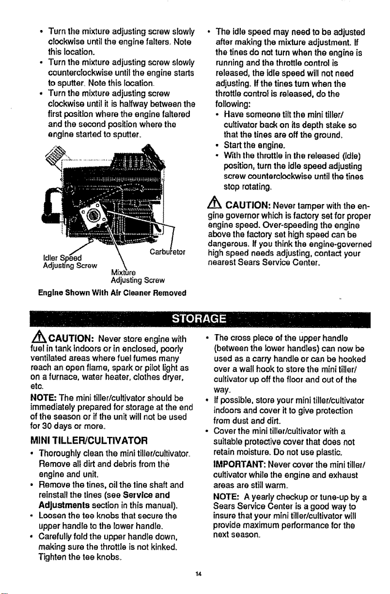
• Turn the mixture adjusting screw slowly
clockwise until the engine falters, Note
this location.
- Turn the mixture adjustingscrew slowly
counterclockwise untilthe engine starts
to sputter. Note this location.
• Turn the mixture adjustingscrew
clockwise untilit ishalfway between the
first positionwhere the engine faltered
and the second position where the
engine startedto sputter.
Idler
Screw
Adjusting Screw
EngineShownWith A|r CleanerRemoved
. The idle speed may need to be adjusted
after making the mixture adjustment° If
the tinesdo not turn when the engine is
runningand the throttle control is
released, the idle speed will notneed
adjusting, if the tines turn when the
throttlecontrol isreleased, do the
following:
• Have someone tiltthe mini tiller/
cultivatorback on its depth stake so
thatthe tines are off the ground.
• Start the engine.
o With the throttle in the released (Idle)
position, turn the idle speed adjusting
screw counterclockwise until the tines
stop rotating.
,/_ CAUTION: Never tamper with the en-
gine governor which is factory satfor proper
engine speed. Over-speeding the engine
above the factory set high speed can be
dangerous. If you think the engine-governed
high speed needs adjusting, contact your
nearest Sears Service Center°
A
_CAUTION: Never store engine with
fuel in tank indoors or in enclosed, poorly
ventilated areas where fuel fumes many
reach an open flame, spark or pilot lightas
on a furnace, water heater, clothes dryer,
etc.
NOTE: The mini tiller/cultivator should be
immediately prepared forstorage at the end
ofthe season or ifthe unitwiUnot be used
for 30 days or more,,
MINi TILLER/CULTIVATOR
• Thoroughly clean the minitilter/cultivator.
Remove alldirt and debris from the
engine and unit.
• Remove the tines, oil the line shaft and
reinstallthe tines (see Service and
Adjustments section in this manual).
• Loosen the tee knobs that secure the
upper handle to the lower handle.
• Carefully fold the upper handle down,
making sure the throttle isnot kinked_
Tighten the tee knobs_
14
The cross piece of the Upperhandle
(between the lower handles) can now be
used as a carry handle or can be hooked
over a wall hook to store the mini tiller/
cultivator up off the floor and outof the
way°
If possible,store your minitiller/cultivator
indoors and cover itto give protection
from dust and dirt.
Cover the minitiller/cultivatorwith a
suitable protective cover that does not
retain moisture. Do not use plastic.
IMPORTANT: Never coverthe minitiller/
cultivatorwhile the engine and exhaust
areas are still warm..
NOTE: A yearly checkup or tune-up by a
Sears Service Center is a good way to
insure that your mini tiller/cultivator will
provide maximum performance for the
next season.
ENGINE
IMPORTAWI': It isimportantto prevent
gum deposits from forming in essential fuel
system parts such as the carburetor, fuel fil-
ter, fuel hose or tank during storage. Also,
experience indicatesthat alcohoi blended
fuels (called gasohotor using ethanol or
methanol) can attract moisture which leads
to separation and formation of acids during
storage_ Acidic gas can damage the fuel
system of an engine while in storage,
• Drain the fuel from the fuel tank into an
approved container outdoors, away from
open flame,
Start and runthe engine until it stops due
to lack of fuel
Pull the starter handle slowly until you
feel resistance due to compression
pressure, then stop,
Release the starter tension slowty to
prevent the engine from reversing due to
compression pressure_ This position wilt
close both the intake and exhaust ports to
prevent corrosion of the piston and
cyl;nder bore,
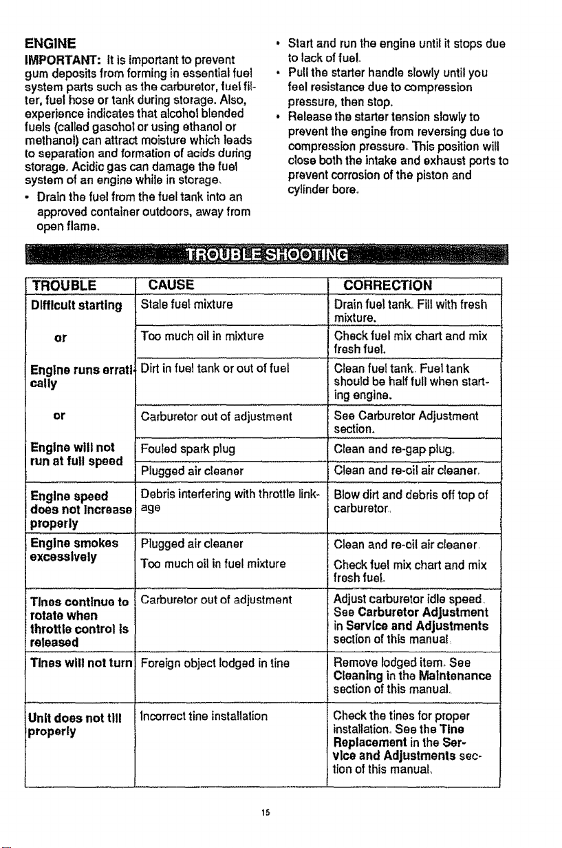
TROUBLE ...... CAUSE CORRECTION
Difficult starting Stale fuel mixture Drain fue!tank_ Fill with fresh
mixture.
or Too mUch oil in mixture Check fuel mix chart and mix
fresh fuel.
Engine runs erratl_ Dirt in fu'el tank or out of fUei.................Clean fuel tank,iFuei"iank
tally should be half full when start-
ing engine.
.... .... =
or Carburetor outof adjustment See Carburetor Adjustment
section,
Engine will not Fouled spark plug Clean and re-gap plug,
run at full speed ..........
Piugged air cleaner .....C_eanand re-oii air clean'e'ii"
Engine speed Debris interferingwiththrottle link- Blow dirtand debris off top of
does not Increase age carburetor,,
properly
Engine
smokes Plugged air cleaner Clean and re-oi! air cleaner
excessively Too much oil infuel mixture Check fuel mix chart and mix
Tines continue to
rotate when
throttle control Is
released
Tines will not turn
Unitdoes not till
properly
Carburetor out ofadjustment
Foreign object lodged in tine
Incorrect line installation
freshfuel
Adjustcarburetor idle speed,
See Carburetor Adjustment
in Service and Adjustments
section of this manual
Remove lodged item_See
Cleaning in the Maintenance
section of this manual,,
Check the tines for proper
installation° See the Ttne
Replacement in the Ser.
vice and Adjustments sec-
tion of this manual,
15
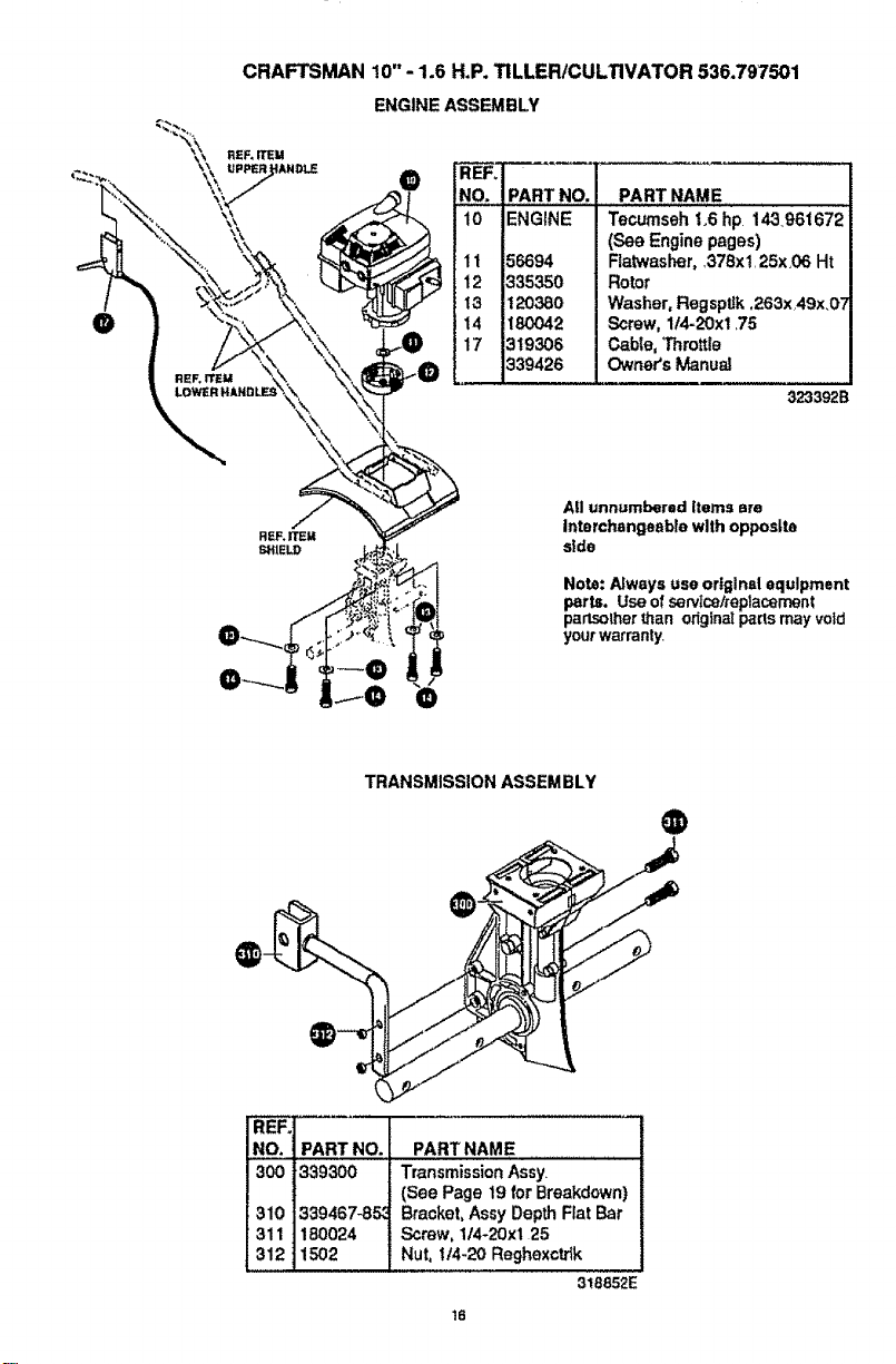
CRAFTSMAN 10" - 1.6 H.P. TILLER/CULTIVATOR 536.797501
ENGINE ASSEMBLY
NO. PART NO.
10 ENGINE
11
12
13
14
17
335350
t2o3eo
1_o42
3!93o6
339426
PART NAME
Tecumseh 1°6 hp 143961672
(See Engine pages)
Flatwasher, 378x1,25x,06 Ht
Rotor
Washer, Regsptik ,263x49x.O'_
Screw, 1/4=20xt _75
C_ble, Throttle
Owner's Manual
323392B
All unnumbered Items are
Interchangeable with opposite
slde
Note: Nways use original equipment
parts. Use of servicetrepiacement
parlsother than odginatpalls may void
yourwarranty.
TRANSMISSION ASSEMBLY
@
131o1339467-85,1
1311] 180024 !
l 3..121ls°2 |
PART NAME
Transmission Assy
(See Page 19 for Breakdown)
Bracket, Assy Depth Fiat Bar
Screw, 1/4-20xl 25
Nut, t/4-20 Reghexctdk
318852E
16

CRAFTSMAN 10"-t.6 H.P. TILLER/CULTIVATOR 536.797501
TINE SHIELD ASSEMBLY
REF,
NO.
48O
48I
482
483
490
491
PART NO. f PART NAME
i309073_633 Tins Shield
273869 iScrew, 1/4-20x5 00
120392 Flatwasher .281x 63x.065
1502 Nut, 1/4-20 Reghexctrfk
56158 Felt Washer 68xl,46x 12
56157-853 iTine, Assy Inner LH
REF.
NQ, PART NO,
492 156155-853i
493 i56!53-853 !
i494 56154-853
495 56123
496 56180
PART NAME
"Fine,Assy Outer LH
"Fine, Assy Inner RH
_ne, Assy Outer RH
Clevis Pin .3tx1..38
Hair Pin 091DiaxI 62Lg
318849C
FLAT BAR ASSEMBLY
@
iREF:} ......
!NO, JPART NO. PART NAME
350 330799-853 Wheel Suppt Assy Drag Stake
._60 333635 Clevis Pin .32tx_75
561 56180 Hair Pin 091Diaxl_62Lg
562 339277 Tire & Rim
663 73664 Nut, Push On 3/8"
318852E
17
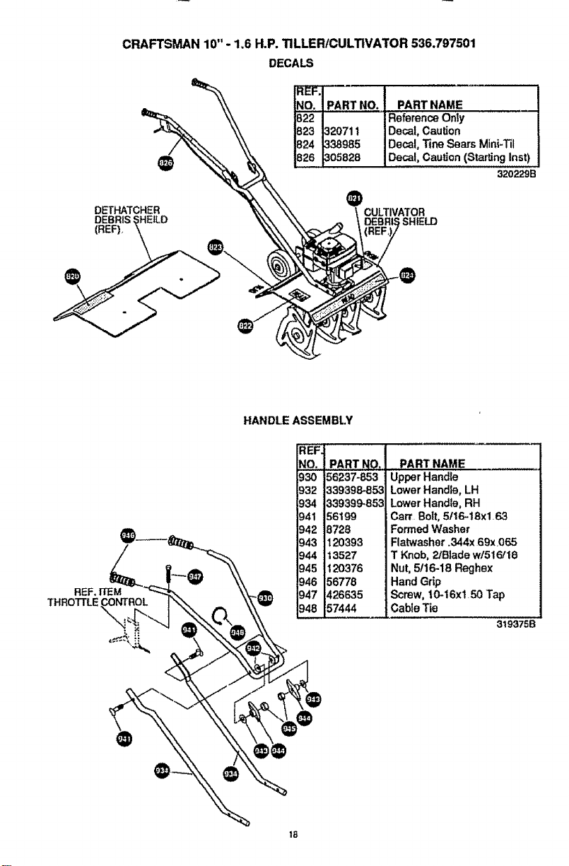
CRAFTSMAN 10"- 1,6 H.P. TILLER/CULTIVATOR 536.797501
DECALS
@
DETHATCHER
DEBRIS
(REF)_
_PART NO. PART NAME
822 | Reference Only
823 ]320711 Decal, Caulk;on
824 1338985 Decal, "line Sears Mini-Til
_305828 Decal, Caution (Starting Inst)
320229B
CULTIVATOR
SHIELD
REF. ITEM
THROTTLE_NT_OL
HANDLE ASSEMBLY
REF.
NO. PART NO .... PART NAME
§30 56237-853 Upper Handle
932
934
941
942
943
944
945
946
947
_48
339398-85,3
339399-853
56199
6728
120393
13527
120376
56778
426635
57444
Lower Handle, LH
Lower Handle, RH
Cart. Bolt, 5/16_18x1.63
Formed Washer
Flatwasher .344x 69x,065
T Knob, ?JB|adew/516/18
Nut. 5/16-18 Reghex
Hand G_ip
Screw, 10-16x150 'Tap
Cable Tie
319375B
18
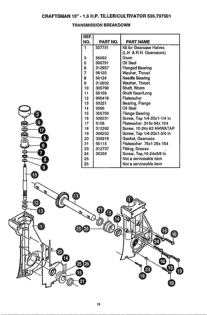
CRAFTSMAN 10" - 1.6 H.P. TILLER/CULTIVATOR 536.797501
TRANSMISSIONBREAKDOWN
REFo
NO. PART NO.
1 337731
3 56692
5 306791
6 312957
7 56125
8 56124
9 312652
10 306790
11 56159
12 996418
13 50221
14 9566
15 306793
t6 308231
17 6106
I8 312292
19 308232
20 338919
21 56115
23 312737
24 35258
25
26
PART NAME
Kit for Gearcase Halves
(LH & RH, Gearcases)
Drum
Oil Seal
Ranged Bearing
Washer, Thrust
Needle Bearing
Washer, Thrust
Shaft, Worm
Shaft Gear!Long
Flatwasher
Bearing, Flange
OilSeal
Flange Bearing
Screw, Tap t14-20x1-1/4 In
Flatwasher o515x 94x_r104
Screw, 10-24x.62 HHWATAP
Screw, Tap 114-20xl-314 in
Gasket, Gearcase
Flatwasher. 76xl 25x 104
Fitting, Grease
Screw, Tap,lO_24x3!8 In
Not a serviceable item
Net a serviceable item
@
t9
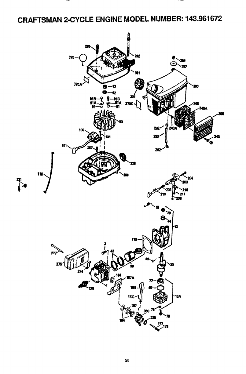
CRAFTSMAN 2-CYCLE ENGINE MODEL NUMBER: 143.961672
20
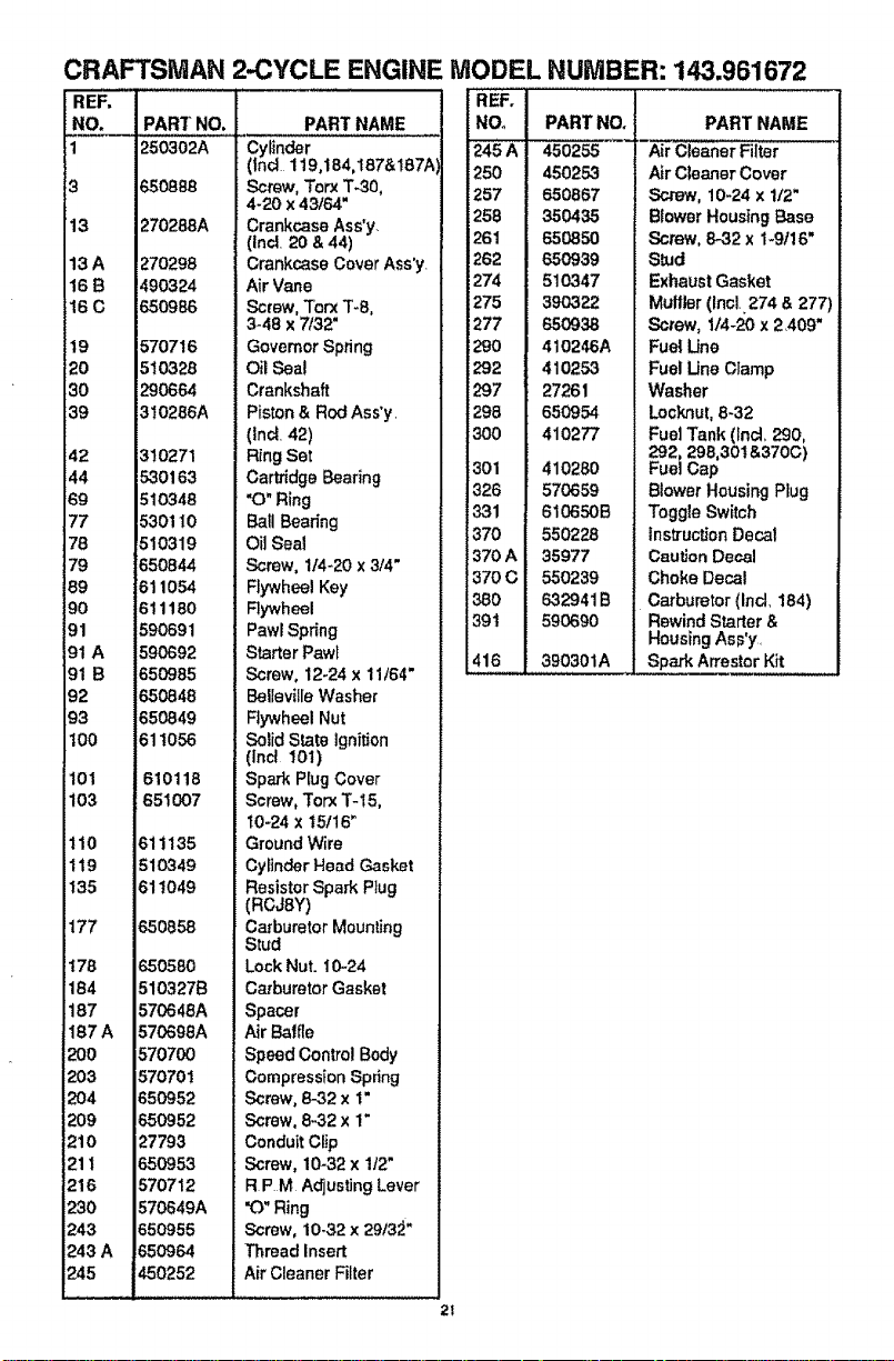
CRAFTSMAN 2-CYCLE ENGINE MODEL
REF,
NO.
1
13
13A
166
160
19
20
30
39
42
44
69
77
78
79
89
90
91
91 A
91 B
92
93
100
101 610118
103 651007
110 611135
119 610349
135 611049
177 650858
I76 650580
184 5103276
187 570648A
187A 570698A
200 570700
i203 570701
i204 650952
i209 650952
1210 27793
211 650953
!216 570712
i230 570649A
243 650955
i243A 65O964
245 450252
PART NO, PART NAME
250302A Cylinder
(lncl 1190184,167&t87A
650888 Screw, Torx %30,
4-20 x 43/64"
270288A Crankcase Ass'y.
(incl. 20 & 44)
1270298 Crankcase Cover Ass'y
490324 Air Vane
650986 Screw, Torx T-8,
3-48 x 7/32"
570716 Governor Spring
510328 Oil Seal
290664 Crankshaft
310286A Piston & Rod Ass'y.
(Ind. 42)
310271 Ring Set
530163 Cartridge Bearing
510348 "O" Ring
530110 Ball Bearing
510319 Oil Seal
650844 Screw, 1t4-20 x 3/4"
811054 Rywheel Key
611160 Rywheel
590691 Pawl Spring
590692 Starter Pawl
650985 Screw, 12-24 x 11/64"
650848 Belleville Washer
650849 Rywheel Nut
611056 Solid State ignition
(lnct t01)
Spark Plug Cover
Screw, Torx T-15,
t0-24 x 15116"
Ground Wire
Cylinder Head Gasket
Resistor Spark Plug
(RCJSY)
Carburetor Mounting
Stud
Lock Nut. 10-24
Carburetor Gasket
Spacer
Air Baffle
Speed Control Body
Compression Spring
Screw, 8-32 x i"
Screw, 8-32 x 1"
Conduit Clip
Screw, 10-32 x 1t2"
R PM Adjusting Lever
"O"Ring
Screw, 10-32 x 2913;_"
Thread Inserl;
Air Cleaner Filter
NUMBER: 143.961672
REF,
NOo
i245A
i250
'.257
i258
261
!282
i274
i275
i277
1290
i297
296
30o
301
326
331
370
370A
370c
380
39t
416
PART NO,
450255
450253
650867
350435
650850
650939
510347
390322
650938
410246A
410253
27261
650954
410277
410280
570659
610650B
550228
35977
550239
632941B
590690
390301A
PART NAME
Air Cleaner Filter
Air Cleaner Cover
Screw, 10-24 x 1/2"
Blower Housing Base
Screw, 8-32 x 1-9t16"
S_ud
Exhaust Gasket
Muffler (Incl,274 & 277
Screw, 1/4-20 x 2409"
Fuel Une
Fuel Une Clamp
Washer
Locknul, 8-32
Fuel Tank (tnd, 290,
292, 296,30t&370C)
Fuel Cap
Blower Housing Plug
Toggle Switch
Instruction Decal
Caution Decal
Choke Decal
Carburetor (Incl, 184)
Rewind Starter &
Housing As_,'y.
Spark Arrestor Kit
2t
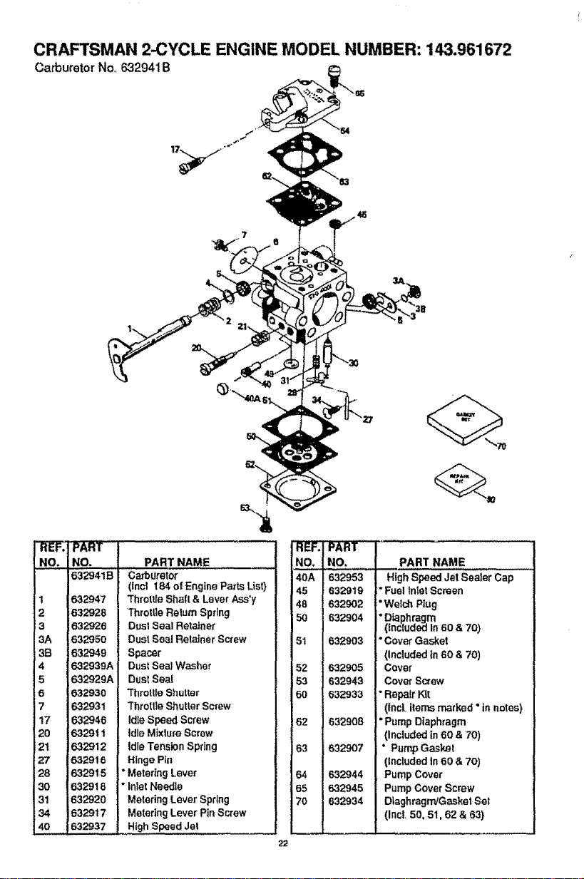
CRAFTSMAN 2-CYCLE ENGINE MODEL NUMBER: 143.961672
Carburetor No,. 632941B
PAR t
NO+ | PART NAME
632941B _ Carburetor
I (Incl t84 of Engine Parts List}
632947 _ ThrottleShaft & LeverAss'y
632928 I "l'hrottle Relum Spring
6.32926 J DustSeal Retainer
632950 _ Dust Seal RetainerScrew
632949 I Spacer
632939A l DustSeal Washer
632929A J DustSeal
632930 _ "ThrottleShutter
632931 _ 3"hrotUaShutterScrew
632946 ] IdleSpeed Screw
632911 I Idle MixtureScrew
632912 _ Idle TensionSpring
632916 I Hinge Pin
632915 J: MeteringLever
632918 | Inlet Needle
131 1632920 | Metering Lever Spring
34 1632917 | Metering Lever Pin Screw
!40 1632937 | High Speed Jet
NO.
40A
45
48
5O
51
52
53
6O
62
63
64
65
70
22
iNO.
632953
6329to
632902
632904
632903
632905
632943
632933
i
632908
i 632907
632944
632945
632934
PART NAME
High Speed Jet Sealer Cap
*Fuel InterScreen
*WelchRug
"Diaphragm
(InctudedIn 60 & 70)
"Cover Gasket
(Included in60 & 70)
Cover
Cover Screw
"Repair Kit
(incloitemsmarked °in notes)
"Pump Diaphragm
(includedin60 & 70)
" PumpGasket
(includedin60 &70)
Pump Cover
Pump CoverScrew
DLaghragmJGasketSe!
(Inct 50, 51,62 & 63)
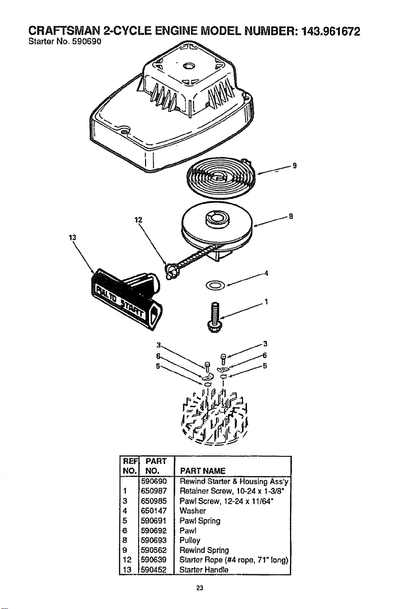
CRAFTSMAN 2-CYCLE ENGINE MODEL NUMBER: 143,961672
Starter No, 590690
12
13
\
REF
NO.
1
3
4
5
6
8
9
12
13
PART
i_9_9o!
p65o_87I
650985
650147
590691
590692
;590693
5_o562
590639
!590452
PART NAME
Rewind Starter & Housing Ass'y,
Retainer Screw, 10-24 x t43/8"
Pawt Screw, 12-24 x 11164"
Washer
Pawl Spring
Pawt
Pulley
Rewind Spring
Starter Rope (#4 rope, 7t" long)
Starter Handle
23
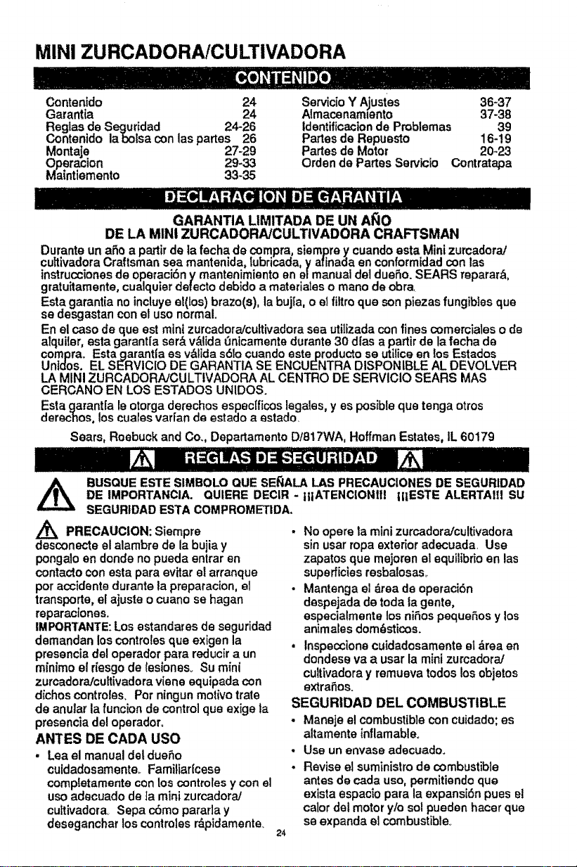
MINI ZURCADORA/CU LTIVADORA
Contenido 24
Garant_a 24
Reglas de Seguridad 24-26
Contenido la bolsa con las partes 26
Montajff 27-29
Opera clon 29-33
Maintiemento 33-35
Servicio Y A_ustes 36-37
Almacenamlento 37-38
Identificacton de Problemas 39
Partes de Repuesto 16-19
Partes de Motor 20-23
Orden de Partes Servicio Contratapa
GARANTIA LIMITADA DE UN AiSle
DE LA MINI ZURCADORA/CULTIVADORA CRAFTSMAN
Durante un a_o a partirde ta fecha de compra, siemprey cuando esta Mini zurcadora/
cuh|vadora Craftsman sea mantenida, lubricada, y afinada an conformidad con las
instruccionesde operaci6n y mantenimiento en e|manuai del dueSo. SEARS reparar_,
gratuitamente, cualquierdetecto debido a materiates o mane de obra.
Esta garantia no incluyest(los) braze(s), la buj_a,o e! filtroqua son plazas fungibles qua
se desgastan con at use normal.
En el case de qua est mini zurcadora/cuttivadora sea utilizada con fines comerciales o de
alquiler, esta garant[a ser& v&lida 0nicamente durante 30 dl'as a partir de la fecha de
compra. Estagarant|a as v&lida s61ocuando este producto se utilice an los Estados
UnIdos. EL SERVIClO DE GARANTIA SE ENCUENTRA DISPONIBLE AL DEVOLVER
LA MINI ZURCADORhJCULTIVADORA AL CENTRO DE SERVICIO SEARS MAS
CERCANO EN LOS ESTADOS UNIDOS.
Esta garant[a le otorga derechos espectficos legales, yes posibtequa tonga otros
derechos0los cuales vaffan de estado a estado.
Sears, Roebuck and Co., Departamento DtB17WA, Hoffman Estates, IL 60179
BLISQUE ESTE SIMBOLO QUE SE_IALA LAS PRECAUCtONES DE SEGURIDAD
DE IMPORTANCIA. OUIERE DECIR -
SEGURtDAD ESTA COMPROMETIDA.
Z_ PRECAUCION: Siempre
desconecte el alambre de la bujiay
pongalo en donde no puada entrar en
contacto con esta para evitar el arranque
per accidente durante la preparacion, el
transporte, el ajuste o cuane se hagen
reparaciones.
IMPORYANTE:Los estandares de seguridad
demandan los controles qua exigen la
presencia del operador para reducir a un
m[nimo el riesgo de lesionesv Su mini
zurcadora/cultivadora viene equipada con
dichos controles. Per ningun motive trate
de anular la funcion de control qua exige ta
presencia del operador.
ANTES DE CADA use
• Lea el manual del due_o
cuidadosamente_ Familiarfcese
completamente con los controles y con el
use adecuado de ta mini zurcadora/
cuttivadora_ Sepa c6mo parafla y
deseganchar los controles r_pidamente.
IttATENCIONIIt tI1ESTE ALERTAItl SU
24
No opera la mini zurcadoraJcultivadora
sin usar rope exterior adecuada. Usa
zapatos qua mejoren el equiiibrioen las
superficies resbalosaso
Mantenga el drea de operaci6n
despejada de toda la genre,
aspecialmente los niSos pequeSos y los
animales dom_sticos.
• Inspeccione cuidadosamente el drea en
dondese va a user la mini zurcadora]
cultivadora y remueva redes los objetos
extremes.
SEGURIDAD DEL COMBUSTIBLE
- Maneje el combustible con cuidado; es
altamente inflamable,
• Use un envase adecuado.
- Revise el suministrode combustible
antes de cada use, permitiendo qua
exista espac]o para la expansi6n pues el
calor del motor y/o sol pueden hacer qua
se expanda el combustible.
• Liana et estanque de combustibFe afuera
con touche cuidadoo Nunca liana el
estanque de combustible en recintos
cerrados. Vuelva a colocar la tapa del
estanque de combustible en forma
segura y limpie el combustible
derramado_
. Nunca remueva la tapa del estanque de
combustibteo agregue combustible a un
motorqua est,. funclonando o qua est&
caliente.
. Nunca almacene combustible o la mini
zurcadora/cultivadora con combustible en
el estanque dentro de un edificioan
donde los gases puedan alcanzar una
llama expuesta_
SEGURIDAD DE OPERAClON
. Nunca permita qua los nifioso
adolescentes j6venes operen la mini
zurcadora/cultivadora Mant6ngalos
aTejadoscuando est_ en operaci6n_
Nunca permita qua losadultos operen la
minizurcadora/cultivadora sin los
conocimientos adecuadoso
• Siempre use anteojos de seguridad o
protecoiones pare los ojos durante la
operacibn, o cuando haga ajustes o
reparaciones, para proteger sus ojos
centre objetos extraSos qua ta mini
zurcaclora/cultivadora pueda lanzar.
• No ponga las manes ni los pies corca o
debajo de partes rotatorias,
. Tenga sumo cuidado cuando opera o
atraviese entradas de autom6viles de
ripio, senderos o caminos° Mant_ngase
alerta de peligros escondidos o tr&fico.
• Tenga cuidado para evitar resbalarse o
caerseo
• Nunca opera la mini zurcadora]
culttvadora sin ias protecclones y tas
planchas adecuadas, o sin otros
dispositosde protecd6n de seguridad en
su lugar.
• Nunca opera la mini zurcadora/
cultivadora a altas velocidades de
transporte an superficies resbalosas_
Mire haole atr,_sy tenga cuidado cuando
retroceda.
• Nunca permita tapresencia de
espectadores cerca de tamini zurcadora/
cultivadora.
• Mantenga a los niSos y a los animales
dom6sticos alejados mientras se est_ en
operaciSn.
• Nunca opere la mini zurcadora/
25
cuttivadora sin buena visibilidado luzo
• No haga funcfonar el motor en recintos
cerrados. Los gases de escape son
peilgresos (conttenen MONOXIDe DE
CARBONO, UN GAS SIN OLOR QUE
CAUSA LA MUERTE).
• Tome todas las precauclones postbles
cuandodeje la minizurcadora]
cuflivadorafiabradera desatendida. Pare
el motor,
• No sobrecargue la capacidad de la mini
zurcadora/curtivadoratratando de
cultivadorr muy profundamente a mucha
velocidado
ALMACENAMIENTO CON
SEGURIDAD
• Siempre refi_rase a tas instrucciones de]
manual del dueSo pare vedficar los
detalles de importancta si la mini
zurcadora/cultivadora se va a almacenar
per un largo per[ode de tiempe
• Nunca almacene la mini zurcadora/
cuJtivadora con combustible en el
estanque de combustible dentro de un
edificioen donde se encuentren
presentes fuentes de ignicibn, tales
come, los calentadores de agua o del
ambiente, secadoras de rope y otros
artefactos parecidos,, Permita qua se
enfrle el motor antes de guardarlo en
algt_nlugar cerrado.
• Mantenga la mini zurcadora!cutttvadora
en condiciones de trabajo seguraso
Revise todos los sujetadores a intervalos
frecuentes pare verificar si est_n
apretados an forma segura,
SEGURIDAD DE REPARACIONES/
AJUSTES
. Despu6s de pegarle a objetos extra_os,
pare el motor. Remueva el alambre de ta
buj|a, y mant_ngalo alejado de _sta para
ev;tar el arranque per accidente. Revise
la mini zurcadora/cultivadora
cuidadosamente para ver_ficar siest&
daSada y repare los daSos antes de
votver a hacer arrancar y operar la mini
zurcadora/cultivadora,
- Si la mini zurcadoraJcuitivadora empieza
a vibrar anormalmente, pare el motor y
reviselnmediatamente la cause. La
vibraciSn, normalmente es un aviso de
problemas,,
• Pare el motor cuando abandone la
posicibn de operacibn,, Tambf_n
desconecte el alambre de la bujia antes
dedestaponarlos brazes de cultivoy
cuando hags repataciones, ajustes o
inspecciones..
• Cuando haga ltmpiezas, reparaciones o
inspecciones,apague et motory
asegfirese que todas las partes en
movimiento se hayan detenido_
• Nunca trate de hacer ajustes mientras el
motor est_ funcionando (excepto
¢uando especiflcemente Io
z_comlende el fabricante)_
ADVERTENCIA: El escape del motor
de este productocent[one productos
qulmicos que se sabe en el estado de
California qua producen cdncer, defectos
de nacimlentoy otros da_os reproductivos.
A
ADVERTENCIA: Esta unidad viene
equipada con un motorde combusti6n
interne y no se debe user sobre, o cerca,
de unterreno nodesarrollado cubiertode
bosques, de arbustos o de c_sped, a
menos qua el sistema de escape del motor
venga equipadocon un amortiguador de
chtspas que cumpla con las leyes locales o
estatales (si existen).. Si se usa un
amortiguadorde chtspas, el eperador debe
mantenerlo en condiclones de trabajo
eflcientes.
En el estado de Califomia_ la lay exige un
amortiguadorde chispas (Seccidn 4442 del
"California Public Resources Code"
(Decreto de Recursos Pdbllcoa de
Caltfomla))o Otros estados puaden center
con otras [eyes parecidas, Las [eyes
federales se aplican en I_ tierras federales.
Su Centre de Servicio Autorizado Sears
rods cercano tiene disponible un
amortiguadorde chispaslsilenciador (veala
seccl0n PARTIESDE REPUESTO an este
manual).
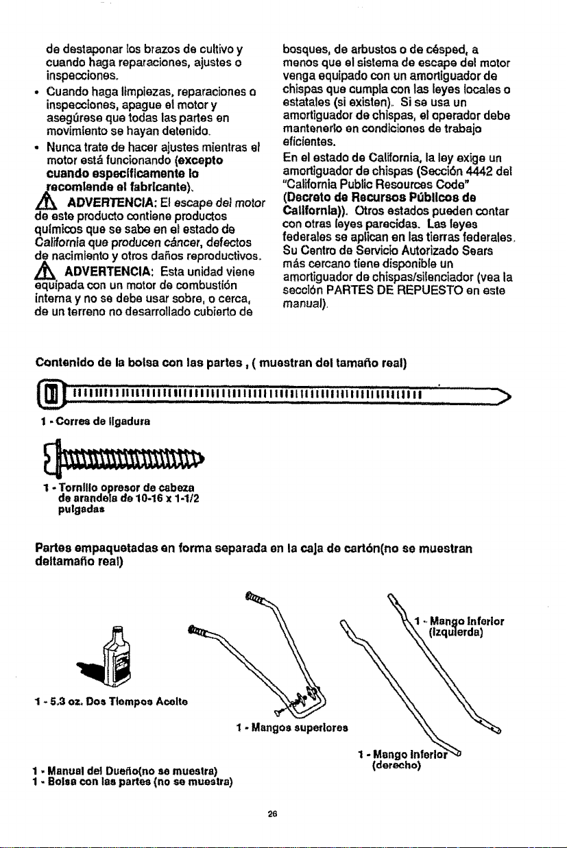
Contenldo de la bolsa con lee partes, ( muestran del tamarto real)
ii i I ill i l,i,i,,i,,i,,,i,iII,i,i Ii._i i i i ii iill iili i i I i,iIi li i i ii Iiii iiI li,ilii,,[,i i i I..........................
1 - Cortes de Ilgaduta
1 -Torn!lieopreaordecabeza
de arandela de 10-16x 1-1/2
pulgadss
>
Partesempaquetadasen formaseparadaenla caJade cart6n(no se muestran
deltamafioreal)
1+5,3 oz+Dos TtemposAcelte
1- Mangossuperlorea
1- Manual de_Dueffo(noae muestre)
1- Boisecon lag partes (no se muestra)
Mangoinfertor
(lzqu|erda)
26
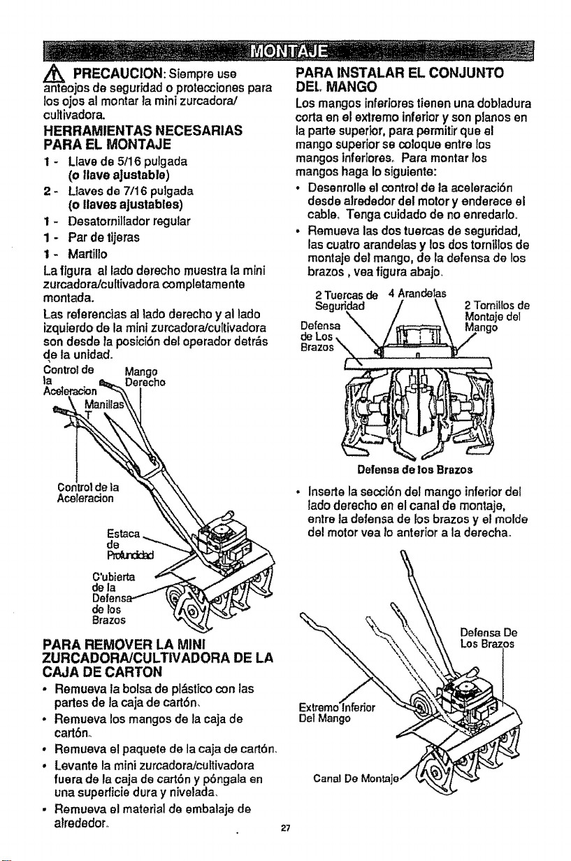
,_ PRECAUCION: Siempre use PARA INSTALAR EL CONJUNTO
anteojos de seguridad o pmtecciones pare
los ojos al montar la mini zurcadora.,'
cu]livadora.
HERRAMIENTAS NECESARIAS
PARA EL MONTAJE
1 - Llavede 5/16 pulgada
(o llave aJustable)
2 - Llaves de 7/16 puigada
(o Itaves aJustables)
1 - Desatorniltador regular
1 - Par de tijeras
1- Martilio
La figura al lado derecho muestra la mini
zurcadora/cuttivadora completamente
montada.
Las referenciasal lado derecho y al lado
izquierdode la mini zurcadora/cultivadora
son desde ta posicidndel operadordetr&s
de launidad.
Controlde la _, _
Aceleracion '_
,4
Defense''r \_f__ _"
delos "_/_
Brazes "1,_
PARA REMOVER LA MINI
ZURCADORA/CULTIVADORA DE LA
CAJA DE CARTON
• Remueva ta bolsa de pl&stico con las
partes de la caja de cartSn,
• Remueva los mangos de la caja de
cartSn+,
, Remueva e! paquete de la caja de cartbn,
• Levante la mini zurcadora/cultivadora
fuera de la caja de cart6n y pSngala en
una supedicie dura y nivelada.
• Remueva el material de embalaje de
alrededor_
DEL MANGO
Los mangos inferiores tienen una dobladura
corta en el exlremo inferiory son pianos en
la parte superior, pare permitirqua el
mango superior se coloque entre los
mangos inferiores° Para montar los
mangos haga Iosiguiente:
. Desenrolle el control de la aceleraciSn
desde alrededor del motor y enderece el
cable+ Tenga cuidado de no enredado,
• Remueva las dos tuercas de seguridad0
las cuatroarandelas y losdos tornillos de
montaje del mango, de la defense de los
brazos, vea figura abajo+
2Tuercasde 4 Arandelas
Seguridad 2TomiIIosde
Defense
de Los
Defensedelos Brazos
lnserte lasecciSn del mango inferiordel
ladoderecho en el canal de montaje,
entre ta defense de los brazos y el molde
del motor yea 1oanterior ala derechao
DefenseDe
Los
Del Mango
27
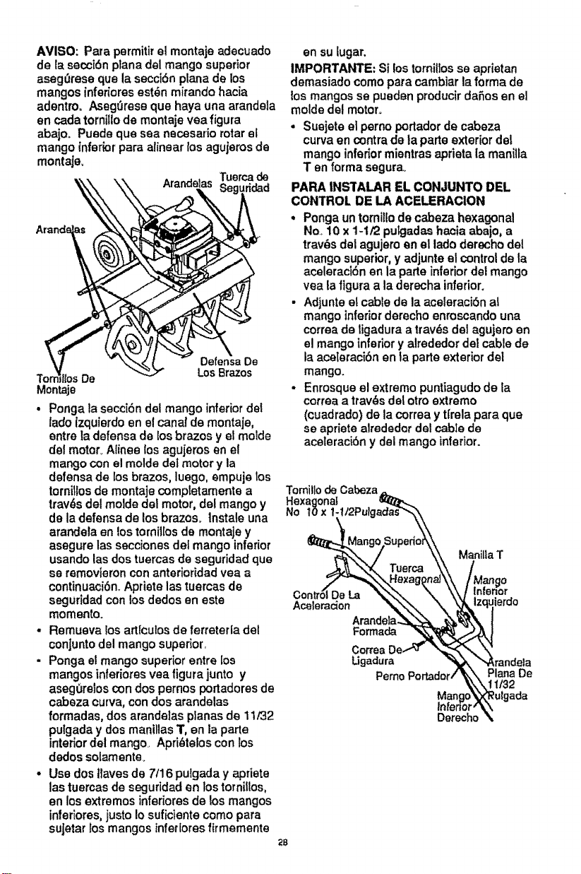
AVISO: Para permitirel montaje adecuado
de la secct6nplane del mango superior
aseg_rese qua la secci6n plane de los
mangos infer_oresest6n mirando hacia
adentro, AsegOrese que haya una arandela
en cada torniliode montaje vea figure
abajoo Puede qua sea necesario rotarel
mango inferior pare alinear los agujeros de
montaje.
Ar de_x Tuercade
\_\ \_ Arand Seguridad
A
TornV_ItosDe _ LosBrazes
Montaje
• Ponga la secci6n del mango inferiorde1
lade izquierdoen el canal de montaje,
entre tadefensa de losbrazes y el molde
del motor_ Aiinee los agujeros en el
mango con el molde del motor y la
defense de los brazes, luego, empuje los
tornilios de montaje comp[etamente a
trav6s del molde del motor, def mango y
de la defense de losbrazes, lnstale una
arandela en los torniiIosde montaje y
asegure las secciones del mango inferior
usando las dos tuercas de seguridad qua
se removieroncon anterioridad vea a
continuaci6n.Apriete las tuercas de
segurtdadcon losdedos en este
momentoo
- Remueva losart[culosde ferreteda del
conJuntodel mango superior.
- Ponga el mango superior entre los
mangos inferiores vea figura junto y
asegOrelos con dos pernos portadoresde
cabeza curva, con dos arandelas
formadas, dos arandelas planes de 11/32
pulgada y dos manillas T, en ta parte
interiordel mango. Apri6telos con los
dedos solamente_
• Use dos ilaves de 7116pulgada y apriete
las tuercas de seguridad en los tornillos,
en los extremes inferiores de ?osmangos
inferiores, justo Iosuficiente come pare
suJetar los mangos tnfedores flrmemente
2B
en su lugar.
IMPORTANTE: Si los tornilIosse aprietan
demasiado come para cambiar la forma de
?osmangosse pueden producir da_os en el
molde de! motor°
• Suejete et perno portador de cabeza
curve en centre de la parte exterior del
mango inferior mientras aprieta la manitla
Ten forma segurao
PARA INSTALAR EL CONJUNTO DEL
CONTROL DE LA ACELERACION
• Ponga untorniilo decabeza hexagonal
No. 10 x 1-1f2 pulgadas hacia abajo, a
trav6s del agujero en el lade derecho del
mango superior,y adjunte el controlde la
aceleracl6n en la parte inferior del mango
yea la figure ala derecha inferior.
• Adjunte el cable de la aceleraci6n at
mango inferior derecho enroscando una
correa de tigaduraa trav6s dei aguiero en
el mango inferior y alrededor del cable de
la aceteracibn en ta parte exterior del
mango.
• Enrosque el extreme puntiagudo de ta
correa a trav6s de!otro extreme
(cuadrado) de la correa y ttrela para qua
so apriete alrededor de! cabIe de
aceleraci6n y del mango inferior.
Tomillode Cabeza
NoHexag°n_':1t2Pulg_adas_,.10x
_--_Man go.SuPeri:t_
_-.T.\. / \\ ManiliaT
Tuor=\\ /
_'-"---_..Hex a_n aJ\\ /Mango
cont iD. ',,,
ordo
Arandela_ t_'_'_k t
Forma= N_J
CorreaDe..,`.`# "%_._'._'_"\"
Ugadura _ _'._randela
Pemo Portader/_k\ plana De
............. _kk_.\t 1lt32
Mango\,x,_ulgada
Inl[erior,'_X
Dereche
AVISO: Un lade de la correa de ligadura
es _spero, y el otto es tiSOoE! lade
,tspero ttene que quedar en laparte
interior de lacurcalura que se lorma
cuando se junlan los extremes de la
correa de ligadura
, Trate de soltar la correa de tigadura, st
se suelta, quiere decir que se ha
amarrado con la parte lisaen la parts
interior de la curvatura. Remueva la
correa de tigadurae invierta la
direcciSn
• Corte la correa en exceso_
LISTA DE REVISION
Antes de operar y de disfrutarde su mini
zurcadoraJcultivadora nuevo, le deseamos
que receiba el meier rendimientoy ta mayor
satisfaccion de este de calidad
HAGA EL FAVOR DE REVISAR LA LISTA
A CONTINUACION:
q Se ban completado redes las
tnstrucoiones de montaje.
_/No quedan partes sueltas en la caja de
cartbn.
q Revise si hay sujetadores sueltos,
AI mismo tiempo que come user su MINI
ZURCADORNCULTIVADORA, preste
atencion extra a los puntos de importancia
que se presentana continuac_on:
qq El tanque de combustible estQ Ileno
con la mezcla correcta de gasoline y
aceite_
_/_t FamiliarIcese con la ubicaci6n y la
funci6n de redes los controles.
Op_relos antes de hacer arrancar el
motor
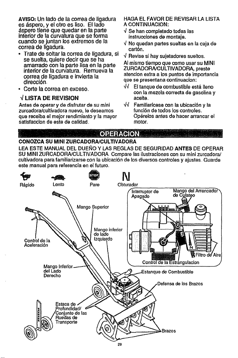
CONOZCA SU MINI ZURCADORA/CULTIVADORA
LEA ESTE MANUAL DEL DUEllO Y LAS REGLAS DE SEGURIDAD ANTES DE OPERAR
SU MINI ZURCADORNCULTIVADORA Compare las ilustracionescon su mini zurcadora/
cultivadorapars familiarizarse con laubicaci6n de losdiversos controles y ajustes. Guards
este manual pars referencia en el future.
5J
R_pido Lento Pare Obturador
0 delArran_dor_
Conh
Acelerac_Sn
Mangoinferior
de lade
Mango Ir
del Lade
Derecho
ulacion
Combustible
,Defense de los Brazes
Estaca de
rofundided/
enjunto de las
uedas de
ransporte
Control de la Ace|eracl6n - Controla la
veloctdad del motor y |a rotaci6n de los
brazos+ La mini zurcadora/culfivadora estb
equipada con un embrague centrffugo qua
engancha al sistema de impulsi6n de los
brazos cuando aumenta la veloddad del
motor.
Palanca de control de la Eetrangulaci6n
- Se usapara ayudar a hacer arrancar un
motorfrlo.
Interruptor de Apagado - Se usa pare
parar el motor.
Mango del Arrancador - El motorde esta
minizurcadora!cultivadoracuenta con
arrancador de culateo f,_cilde tirar.
Estaca de Profundidad/Conjunto de las
ruadas de transporte- Se usa (con las
ruedas levantadas) cuando seest&
labrando o cultivando pare ajustar la
profundidad dot oorte. Tambi_n actt_a como
un freno pare ayudar al operador a
controlar la direcci6n y ta velocidad de la
untdad+
La estaca de profundidad/conjunto de las
ruedas de transporte (con las ruedas
bajadas) se puede user para transportar la
untdad+
COMO USAR SU ZURCADORA/
CULTIVADORA
Z_ ADVERTENCIA: La operaci6n de esta
minizurcadora!cuhivadora puede hacer qua
salten objetos extra_os dentin de sus ojos,
to qua pue de producir dafios graves en
&stos. Siempre use ant_jos de seguridad o
protecciones pare los ojos a! operar la mini
zurcadora/cultivadora+
o Suette el control de ta aceleraci6n pare
parer los brazos,,
• Mueva el interruptor de apagado en el
motor ala posici6nde "APAGADO"
(OFF).
PARA OPERAR LA MINI
ZURCADORA/CULTIVADORA
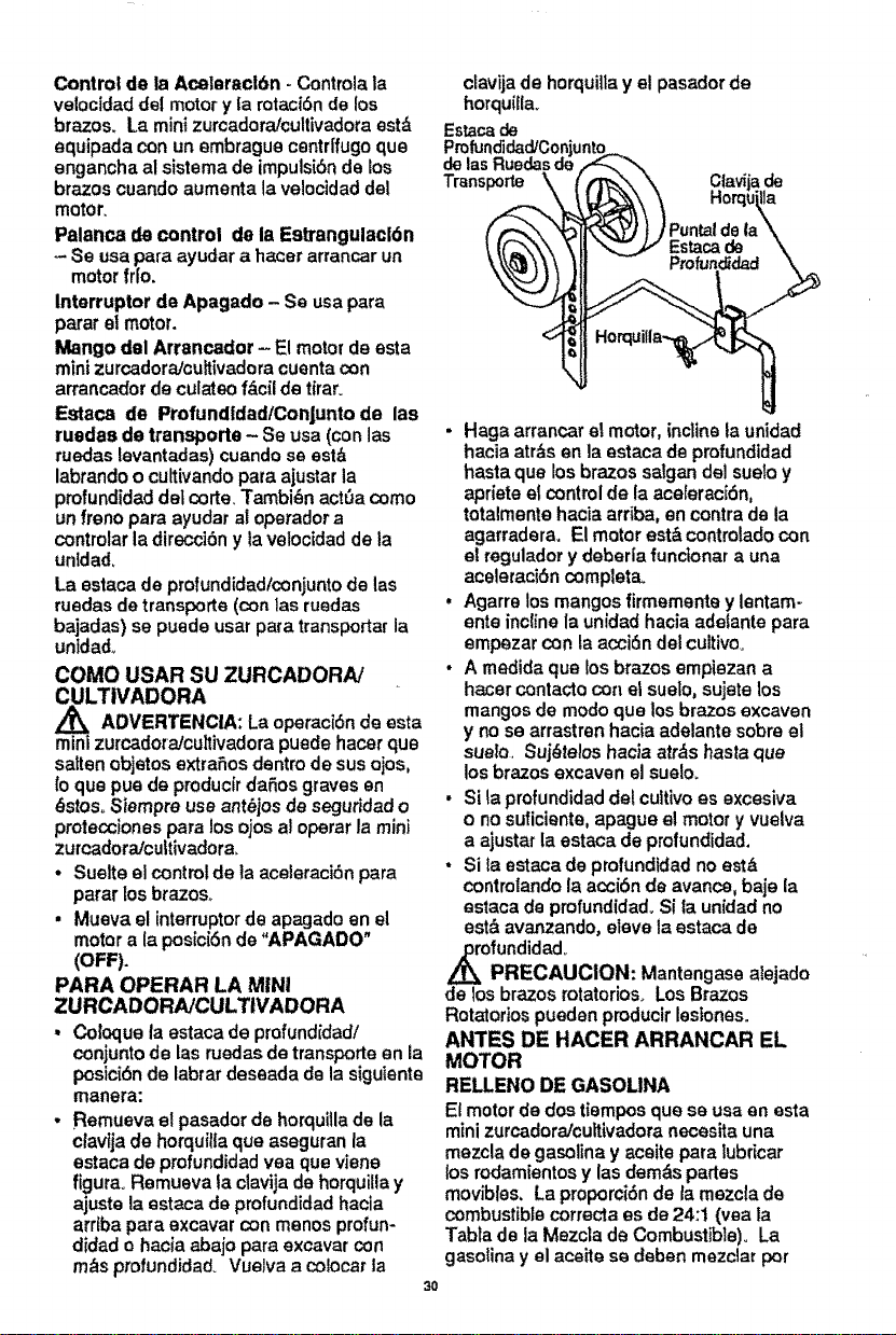
• Coloque la estaca de profund[dadi
conjunto de las ruedas de transporte en la
pesici6n de labrar deseada de la siguiente
manera:
• Remueva el pasador de horquiilade la
clav_jade horquilla qua aseguran la
estaca de profundidadyea qua viene
figure+Remueva fa clavija de horquilla y
ajuste la estaca de profundidadhacia
arr_bapare excavar con menos profun-
didad o hacia abajo para excavar con
m_s ptofundidad+ Vuelva a colocar la
3O
ctavijade horquilla y el pasador de
horquiUa+
Estacade
de las
Transporte
• Haga arrancar el motor, incline ta unidad
hacia atr_s en la estaca de profundidad
hasta qua los brazos salgan del suelo y
apriete el control de la aceleraci6n,
totalmente hacia arriba, en contra de la
agarradera+ El motor est& controladocon
at regulador ydeberla functonar a una
aceleraci6n completaL
• Agarre los mangosfirmemente y lentam-
ente incline la unidad hacia adetante para
empezar con laacci6n del cultivo°
• A mad|de qua los brazos empiezan a
hacer contacto con el suelo, sujete los
mangos de modo qua los brazos excaven
y no se arrastren hacia adelante sobra el
sue_o+Suj_telos hacia atr,_s haste qua
los brazos excaven el suelo+
• Si la profundidaddel cultivo es excesiva
o no suficiente, apague el motor y vuelva
a ajustar la estaca de profundidad.
• Sita estaca de profundldad no est&
controlando la acci6n de avance, baje la
estate de profundidad+Si la un[dadno
est& avanzando, clave ia estaca de
ofundidado
PRECAUCION: Mantengase alejado
de los brazos rotatorios+Los Brazos
Rotatorios pueden produclr lestones+
ANTES DE HACER ARRANCAR EL
MOTOR
RELLENO DE GASOLINA
El motor de dos tiempos qua se usa en esta
mini zurcadora/cultivadora necesita una
mezcla de gasoline y aceite pare lubricar
los rodamientos y las demds partes
movibles. La proporciSnde la mezcla de
combustible correcta es de 24:t (yea la
Tabta de la Mezcla de Combustible). La
gasoline y el ace|to se deben mezclar per
anticipadoenunenvasedegasolinalimpio.
Stempreusegasolinanueva,limplaysin
plpmo.
Z_ PRECAUCION: La gasolina es
inflamab]e y se tiene qua tener cuidado
cuando se maneje o atmacene. No liens el
estanque de combustible mientras qua la
mini zurcadorafcuitivadora esta
funclonando, cuando esta csliente o
cuando esta en un recinto cerradoo
Mantengafa alejada de una llama expuesta,
de las chispss electricas y no fume cuando
mezole el combustible o cuando liens et
estanque de combustible,, Nunca ltene el
estanque de combustible completamente:
sine qua liens el estanque hasta dentro de
1/4-1/2 PuTgada desde ta parts superior
para permitir la expansion del combustible,
Siempre liens el estanque de combustible
afuera y use un embudo o un pico para
evitar el derrameo Asegurese de limpiar
rode e) combustible derramado antes de
hacer arrancar el motor,,
Almscene ta gasolina envase aprobado y
limpio y mantenga la tapa de este en su
)ugar., Guards la gasolina en un lugar
fresco y bien ventilado: nuncs en la casa,,
Nunca compre mas gaselina qua laque
necesita para 30 dias para asegurar la
volatilidad, La gasolina tiene come fin '
servir de combustible en motores de
combustion interna; per 1otanto, no use Is
gasolfna par ningun otro fin° Dado qua a
touches niSos les gusta el olor de la
gasolina, mantengala alejada de su alcance
puss losvaperes son pe_igrosos de aspirar,
asi come explosive.
m_caADVERTENCIA: La experiencia ha
do qua loscombustibres mezclados
con alcohol (conocidos come gasohol, o el
use de etsnol o metanol) pueden atraer la
humedad, la qua conduce a laseparaciSn y
formaci6n de &cidos durante el
almacenamiento., La gasolina actdica
puede daSar ei sistema del combustible de
un motor durante el almacenamiento. Para
evitar los problemas con el motor, se debe
vaciar el sistema de combustible antes de
guardarto per un per|ode de 30 dtaso m&s.,
Vsct'e el estanque de combustible, haga
arrancar e] motor y h_.gatofuncionar hasta
qua las l(neas del combustible y el
carburador queden vacloso La prSxima
temporada use combustible nuevo, Vea tas
instrucciones de Almacenamtento para
m&s informaciSn, Nunca use productos de
limpieza para el motor o para el carburador
en el estanque del combustible, puss se
pueden producirdaSos permanenteso
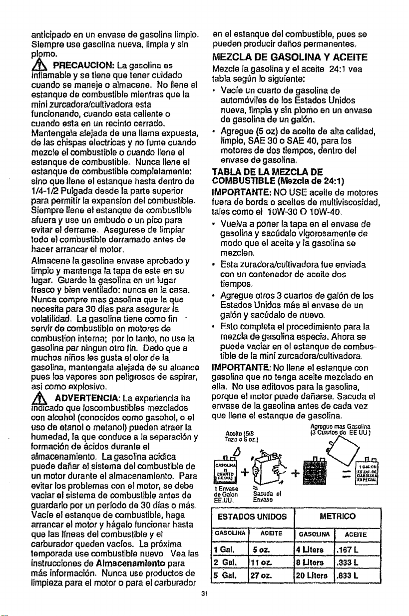
MEZCLA DE GASOLINA Y ACEITE
Mezcle Is gasolina y el aceite 24:1 vea
tabla seg_n Io siguienta:
• Vac|e un cuarto de gasolina de
autombviles de los Estados Unidos
nueva, timpiay sin plomo en un envase
de gasotina de un galSn.
• Agregue (5 oz) de aceite de alta calidad,
timpio,SAE 30 o SAE 40, para los
motores de dos tiempos, dentro def
envase de gssolinao
YABLA DE LA MPTCLA DE
COMBUSTIBLE (Mezcla de 24:1)
IMPORTANTE: NO USE aceite de motores
fuera de borda o aceites de multiviscosidad,
tales come el 10W-30 O IOW-40,
• Vuelva a poner la tapa en el envase de
gasolina y sacudalo vigorosamente de
mode qua el sceite y Is gaso]ina se
mezcleno
• Esta zuradora!cultivadora rue enviada
con un contenedor de aceite dos
tfempes,
• Agregue otros 3 cuartos de galSn de los
Estados Unidos m&s al envase de un
galSn y sacOdalo de nuevoo
- Esto completa el procedimiento para la
mezcla de gasolina especiao Ahora se
puede vaciar en el estanque de combus-
tible de la mini zurcadora/cultivadorao
IMPORTAWI'E: No Ilene el estanque con
gasolina qua no tengs sceite mezclado en
ella. No use sditovos para la gasotina,
porque el motor puede daSarse., Sacuda el
envase de la gasolina antes de cada vez
que llene el estanque de gasolina,
Agrsgue mas G_olina
Aceifo(518 (3Cuar_os EEUU )
T_r, o ,5oz.)
-+
I Envase
doGalon Sa_dt_ e_
E;E,UU. Env'a_8
ESTADOS UNIDOS
GASOUNA ACEITE
1Gal. 5oz.
2 Gal. !11oz.
5 Gal. 270z.
METRICO
OASOU_ ACeTE
4 Uters- .167L
8 Liters ,333 L
20 Liters 1.833L
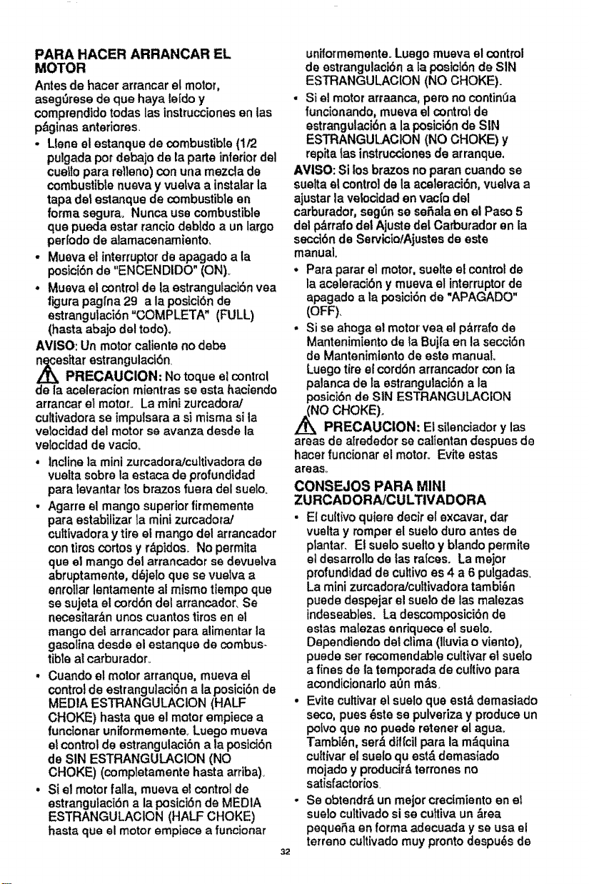
PARAHACERARRANCAREL
MOTOR
Antesdehacerarrancar el motor,
asegt3rese de que haya IeIdo y
comprendidotodas las instruccionesen las
p_ginas anterlores.
•Llene el estanque de combustibte (1/2
pulgada pot debajo de la parte interior del
cue_lopare relleno) con una mezcla de
combustible nuava y vuelva a instalar la
tape del estanque de combustibte en
forma segura, Nunca use combustible
qua pueda estar rancio debldo a un largo
peHodo de alamacenamiento,
. Mueva el interruptorde apagado ala
posicibn de "ENGENDIDO" (ON)_
• Mueva el control de la estrangutaci6n vea
figure paglna 29 ala posici6n de
estrangulaci6n "GOMPLETA" (FULL)
(haste abajo del todo),
AVISO: Un motor caliente no debe
,_es_ar estrangulacibn,
PRECAUCION: No toque el control
de la aceleracion mientras se esta haciendo
arrancar et motor. La mini zurcadora]
cultivadora se impulsara a si misma sila
velocidad del motorse avanza desde la
velocidad de vac[o_
• inclinela mini zurcadora/cultivadora do
vuelta sobre la estaca de profundidad
para ievantar los brazos fuera del suelo.
• Agarre el mango superior firmemente
pare estabilizar la mini zurcadora!
cultivadora y tire el mango del arrancador
con tiroscortos y r&pidos. No permita
qua el mango del arrancador se devuelva
abruptamente, d_jelo que se vuelva a
enrotlarlentamente al mismo tiempo que
se sujeta el cord6ndel arrancador. Se
necesitarbn unos cuantostiros en el
mango def arrancador pare alimentar la
gasoline desde el estanque de combus-
tibia al carburador_
• Cuando el motor arranque, mueva el
controlde estrangulaci6n ala posici6n de
MEDIA ESTRANGULAClON (HALF
CHOKE) haste qua el motor empiece a
funclonar uniformemente_Luego mueva
et control de estrangulaci6n ala posici6n
de SIN ESTRANGULACION (NO
CHOKE) (completamente hasta arriba),.
. Si el motor falla, mueva el control de
estrangutaci6n a laposici6n de MEDIA
ESTRANGULAClON (HALF CHOKE)
hasta qua el motor empiece afuncionar
32
uniformemente. Luego mueva el control
de estrangulack_n ala posict6n de SIN
ESTRANGULACION (NO CHOKE).
• Si e! motor arraanca, pero no contintla
funclonando, mueva e! controt de
estrangulaci6n ala posici6n de SIN
ESTRANGULACION (NO CHOKE) y
repita tas instrucdones de arranque,
AVISO: Si los brazos noparan cuando se
suelta el controlde la aceleraci6n, vuelva a
ajustar la velocidad envaclo del
carburador, seg_n se seSala en el Paso 5
del p_rralo dei Ajuste del Carburador en la
secc_bnde Sen,'icio/Ajustesde este
manual,
. Para parar el motor, suette el control de
la aceleraci6n y mueva el interruptor de
apagado ala posici6n de "APAGADO"
(OFF)_
• Si se ahoga el motor vea el p&rrafode
Mantenimientode la Bujia en ta secci6n
de Mantenimiento de este manual.
Luego tire el cord6n arrancador con la
palanca de la estrangutaci6n ala
posici6nde SIN ESTRANGULACION
/_NO CHOKE).
PRECAUCION: El silenciador y las
areas de alrededor se calientan despues de
hacer funcionar el motor. Evite estas
areas..
CONSEJOS PARA MINI
ZURCADORA/CULTIVADORA
• Elcultivoquiere decir el excavar, dar
vuelta y romperel sueloduro antes de
plantar. Et suelo sueltoy blando permite
el desarrollode las raices. La major
profundidadde cuttivoes 4 a 6 pulgadas.
La mini zurcadora/cultivadora tambi_n
puede despejar el sueto de las matezas
indeseables, La descomposici6n de
estas maiezas enriquece el sueto_
Dependiendo del clima (lluvia o viento),
puede set recomendable cultivar et suelo
a fines de la temporada de cultivopara
acondicionarlo a0n m&s_
• Evite cultivarel suelo que est& demasiado
seco, pues _ste se pulveriza y produceun
pofvoqua no puede retener el ague°
Tambi_n, ser&dif_cilpara la m,4quina
cultivarel suelo quest& demasiado
mojado y producir&terrones no
satisfactorios
- Se obtendr& un major crecimiento en el
suelo cuttivado si se cultiva un &rea
pequeSa en forma adecuada y so usa el
terreno cultivado muy pronto despu_s de
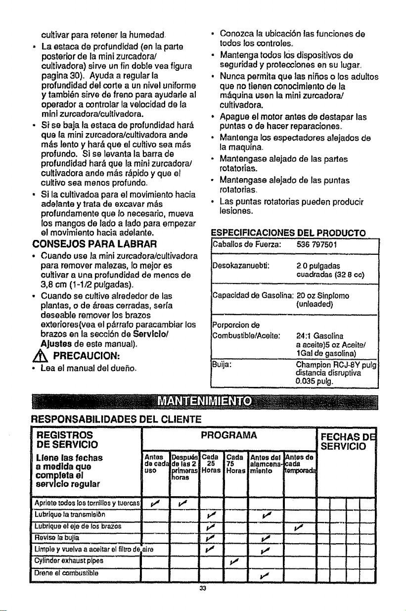
cultivar pare retener la humedad
. La estaca de profundtdad (an la porte
posterior de la mini zurcadora/
culttvadora)sirra un fin dob]e vea figure
paglna 30), Ayuda a regular la
profundidad del corte a un nivel uniforms
ytambi_n sirve de freno pars ayudarle al
operador a controlar la veloc[dad de la
mini zu rcadora/cuitivadora.
. Si se baja la estaca de profundidad her&
qua fa mini zurcadora/cultivadora ands
m&s lento y her& qua el cu_tivosea m_s
profundo. Si se levanta la barra de
profundidad hat& qua la mini zurcadorai
cuitivadora ands m&s r&pido y qua el
cultivo sea manes profundo_
• Si la cultivadoa pare e] movimiento hacia
adefante y irate de excavar m&s
profundamente qua lo necesario, mueva
losmangos de lade a lade para empezar
el movimiento hacia adelante,
CONSEJOS PARA LABRAR
• Cuando use/a mini zurcadoraicultivadora
pare remover malezas, lo major es
ouitivar a una profund[dad de manes de
3,8 cm (!-i/2 pulgadas),,
• Cuando se cultive alrededor de las
ptantas, o de &teas cerradas, serfa
deseable remover los brazes
exteriores(vea el p_rrafo paracambiar los
brazes en la secciSn de Servtclol
AJustes de este manuaf)o
Z_ PRECAUCION:
. Lea el manual del due_o_
• Conozca la ubicac[6n las funcionesde
todos loscontro]eSo
• Mantenga lodes 10sdispositivos de
seguridad y prolecciones en su lugar,,
• Nunca permita que las nifios o ros aduttos
qua no tienen conocimientode la
m,_quina usen la mini zurcadora/
culttvadora.
• Apague el motor antes de destapar las
puntas o de hacer reparaciones_
• Mantenga losespectadores alejados de
la maquina.
• Mantengase alejado de las partes
rotatoriaso
• Mantengase alejado de las punlas
rotatorias.
• Las puntas rotatofias pueden producir
lesiones.
ESPECIFICACIONES DEL PRODUCTO
Caba!]osdeFuerza: 536 797501
Desokazanuebti: 2.0pulgadas
cuadPadas (32 8 ¢¢)
CapaoidaddeGasoline:20oz Sinplorno
(unleaded)
Porpordonde
Combustib]etAceite; 24:1Gasoline
a aceite)5oz Aceite/
1Galde gasoline)
Buija: ChampionRCJ-SYpulg
distandadisruptive
0.035pulg.
RESPONSABILIDADES DEL CLIENTE
REGISTROS PROGRAMA FECHAS DE
DE SERVICIO SERVICIO
Llene las feohas Antes ,3espu_ Cada Cada Antes del _,ntee de
a medlda que de cada 3s lee 2 25 75 alamcoaa- :ada
completael use prtmo_'as Hores Horas m_ento _empor_
eervlclo regular noras
Apflete zodos los tornl!los y _ercas ! p__ ................ ................. - .....
Lubflque ta b'ansrnlsibn P_ e_ z
LUbr[que el eje de los brazes ..... ! Jvs
Revise _ bujta pJ ........... pJ ........... : ....... : .....
Urnpieyvuelvaa aceitarelflllmdEaim /,J
cylinderexhaustpipes .vl :...............;.................... -
Droneet combustible v _
33
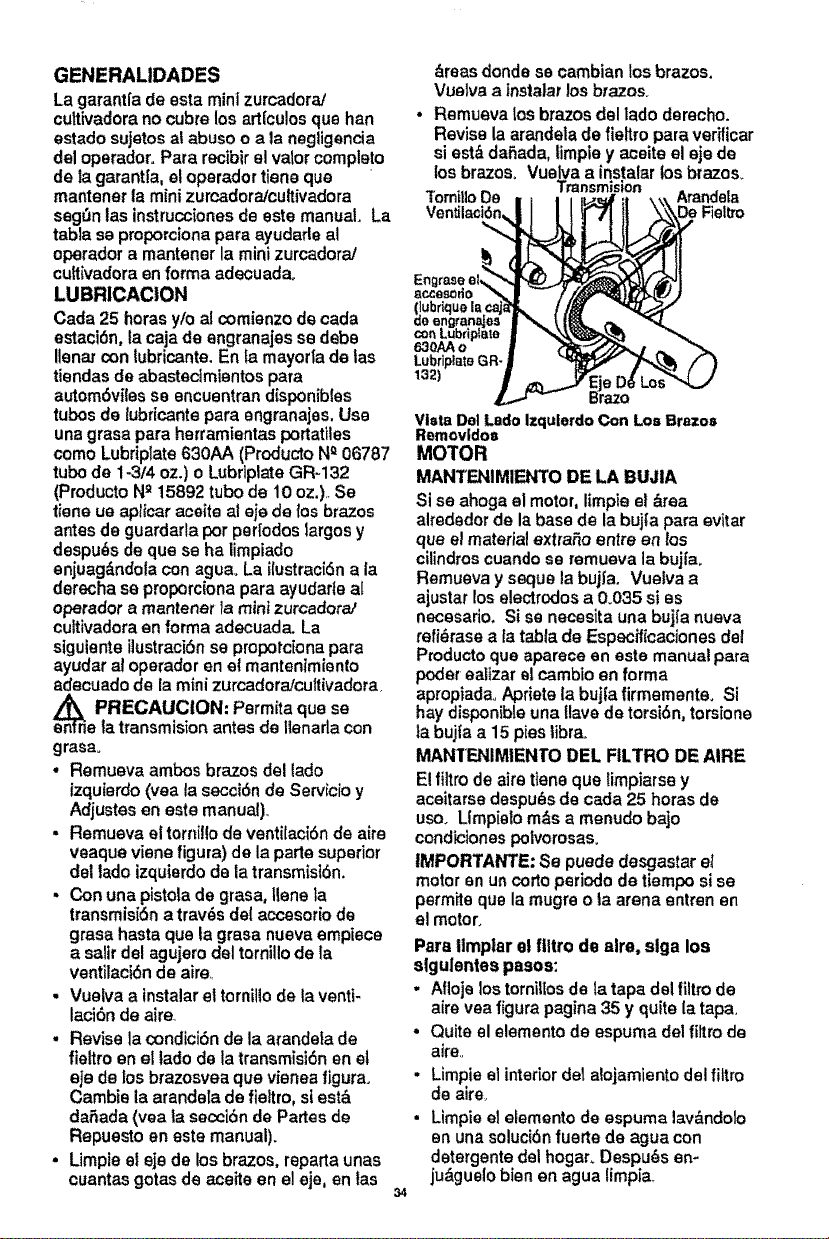
GENERALIDADES
La garantfa de esta mini zurcadorai
cultivadora no cubre los art{culos que hen
estado sujetos al abuso o ata neg]igencia
del operador° Pare recibir el vator completo
de la garantia, et operador tiene que
mantener la mini zumadora/cultivadora
seg_tn las instrucciones de este manual. La
table se proporcionapara ayudarle al
operador a mantener la mini zurcadora/
cuttivadora en forma adecuadao
LUBR1CACiON
Cada 25 horasy/o al comienzo de cada
estaci6n, facaja de engranajes se debe
lienar con lubricante. En la mayoda de tas
tiendas de abastecimientos para
autom6viles se encuentran d[sponibles
tubos de tubficante para engranajes, Use
una grasa pare herramientas portatlles
como Lubriplate 630AA (Producto N_06787
tubo de 1-3/4 oz.) o Lubriplate GR-132
(Producto N_ 15892 tubo de 10 oz.),.Se
tiene ue ap/icar aceite al eie de los brazos
antes de guardarla por periodos largos y
despu_s de que se ha limpiado
enjuag&ndola con aguao La ilustracidn ala
derecha se proporclona para ayudarte al
operador a mantenar la mini zurcadora!
cuttivadora en forma adecuada. La
siguiente ilustraci6n se propotciona para
ayudar al operador en el mantentmiento
adecuado de la mini zurcadora/cultivadora,
en_n PRECAUCION: Permita que se
e la transmision antes de llenarla con
grasao
• Remueva ambos brazos del 1ado
izquierdo (vea la secci6n de Servicio y
Adjustesen este manual)°
= Remueva el tornillo de ventilaciSn de aire
veaque viene figure) de la parte superior
del lado izquierdo de la transmist6n.
• Con una pistola de grasa, Ilene la
transmisi6n a trav_s del accesorio de
grasa hasta que la grasa nueva empiece
a salir del agujero del torni!lo de la
ventilaci6n de aire
. Vuelva a instalar el tornillo de ta venti-
laci6n de aire
. Revise la condici6n de la arandeta de
fieltro en el tado de la transmisi6n en et
eje de los brazosvea que vienea figure.
Cambie la arandeta de fieltro, si est,.
daSada (yea la secci6n de Partes de
Repuesto en este manual).
• Limpie el eje de losbrazos, reparta unas
cuantas gores de aceite en el eje, en las
34
areas donde se cambian los brazos.
Vuelva a insta|ar los brazos.
• Remueva los brazos del lado derecho.
Revise la arandela de fieltro pare verfticar
si est_ da,Sada, timpie y aceite el eje de
los brazos, Vuelva a instalar los brazos_
Transmision
Tomit|oDe i _ = =l_'=_f
(lubrtquelacaja_k //._ "
con Lubriplsie | -"_,,_,
Lubripl_ts GR_ #
Brazo
Vista DelLado IzqulerdoCon Los Brazos
Removido=
MOTOR
MANTENIMIENTO DE LA BUJIA
Si se ahoga el motor, Iimpie el area
alrededorde la base de la bujta para evitar
que e! materialextraSo entre en los
cilindroscuando se remueva la buj{a.
Remueva y sequela bujfa. Vuelva a
ajustar los electrodos a 0.035 si es
necesado. Si se necesita una bujfa nueva
refi_rase ala table de Especificaciones del
Producto que aparece an este manual pare
poder eallzar sl cambio en forma
apropiadao Apriete la bujfa firmemente. Si
hay disponible una Uavede torsidn, torsione
la bujfa a 15 pies libra,
MANTFJ',ilMIENTO DEL FILTRO DE AIRE
El tiltro de aire tiene que limpiarse y
aceitarse despu_s de cada 25 horas de
uso. Llmpielo m_s a menudo bajo
condicionespolvorosas.
IMPORTAWrE, Se puede desgaslar el
motor en uncorto periodo de tiempo sise
permite que la mugre o la arena entrenen
el motor°
Pare llmpiar el filtro de alre. slga los
slgulentes pesos:
• Afloje los tornittosde la tape del filtro de
aire yea figure pagina 35 y quite la tape.
• Quite el elemento de espuma del filtrode
aire,
. Limpie el interior de1alojamiento del filtro
de aire_
• Limpie el elemento de espuma lav&ndolo
en una soluci6n fuerte de ague con
detergente del hogar. Despu_s en-
ju&guelo bienen ague timpia,
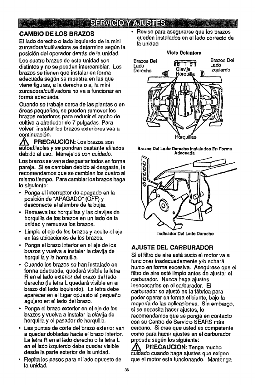
CAMBIO DE LOS BRAZOS
El ladoderecho o lado izquierdode ra mini
zurcadoraJcuitivadorase determina segOnla
posict6n del operador detr&sde la unidado
Los cuatrobrazos de esta un_dadson
disttntosy no se pueden intercambiaro Los
brazos se tienen qua instalaren forma
adecuada seg_n se muestra en las que
viene figures, a la derecha o a, _amini
zurcadoraicuitivadora no va a funcionar en
forrna adecuadao
Cuando se trabaje cerca de las plantas o en
&reas pequefias, se pueden remover los
brazos exteriores para reducir et anchode
cultivoa alrededor de 7 puFgadas.Pare
votver instalar los brazos exteriores vea a
continuaciSn.
PRECAUCION: Los brazos son
autoatilables y se pondran bastante afilados
debido al usoo Manejelos con cuidado_
Los brazosse vana desgastar todos anforma
persia, Si se cambfan debido aldesgaste, le
recomendamos que se cambien los cuatro al
mismotiempo. Paracambiar Iosbrazos haga
lo siguiente:
• Ponga el interruptorde apagado en la
postctSnde "APAGADO" (OFF) y
desconecte el atambre de la bujia.
o Remueva las horquillas y las clavijas de
horquilla de los brazos an un tado de la
unidad y remueva los brazos,
, Limple el eje de los brazos y aceite el eje
en las ubicadones de los brazos..
• Ponga elbraze interior en el eje de los
brazos y vuelva a instalar la clavija de
horquilla y la horqui!ia_
• Cuando los brazos se han instatado en
lorma adecuada, quedar& visible laletra
R en el lado exterior dei brazo dot lado
derecho (la letra L quedar&visible en el
brazo dot lado izquierdo)- La letra debe
aparecer en el lugar opuesto ai pequeSo
agujero en el ]ado del brazoo
• Ponga el brazo exterior en el eje de los
brazos y vuelva a instalar la ciavija de
horquitla y el pasador de horquilla.
• Las puntas de cotte del braze exterior van
a quedar dobladas hacia el brazo interior.
La letra R en el lado derecho o la letra L
en el lado izquierdodebe quedar visible
desde la parte exterior de la unidad.
° Repita los pasos para el fado opuesto de
la unidad.
36
• Revise pare asegurarse que los brazos
queden instalados en el lado correcto de
la unidad.
Vista Delantera
Brazos Del _ Brazos Del
Lado Lado
Derecho Izqu{erdo
Brazos De! Lado Do_,ocho Instalados En Forma
Adocuada
........1
Indlcador Dol Lsdo Derecho
AJUSTE DEL CARBURADOR
Si el_tro de airs est_ sucio el motor va a
funcionar inadscuadamente y/o ocher&
humo en forma excesiva° Asegurese que el
filtro de airs est_ limpioantes de ajustar el
carburador. Nunca haga ajustes
innecesarios enel carburadoro El
carburador se ajustb an laf&brtca para
poder operar en forma eficiente, bajo la
mayod;a de las aplicacionesoSin embargo,
sise necesita hacer ajustes, le
recomnendamosque se ponga en contacto
con su Centro de Servicio SEARS m&s
cercanoo Si cree que usted es competente
como pare hacer ajustes en el carburador
proceda seg(tn lossiguiente:
PRECAUCION: Tonga mucho
cuidadocuando haga ajustes que exigen
qua el motoreste funcionando.. Mantenga
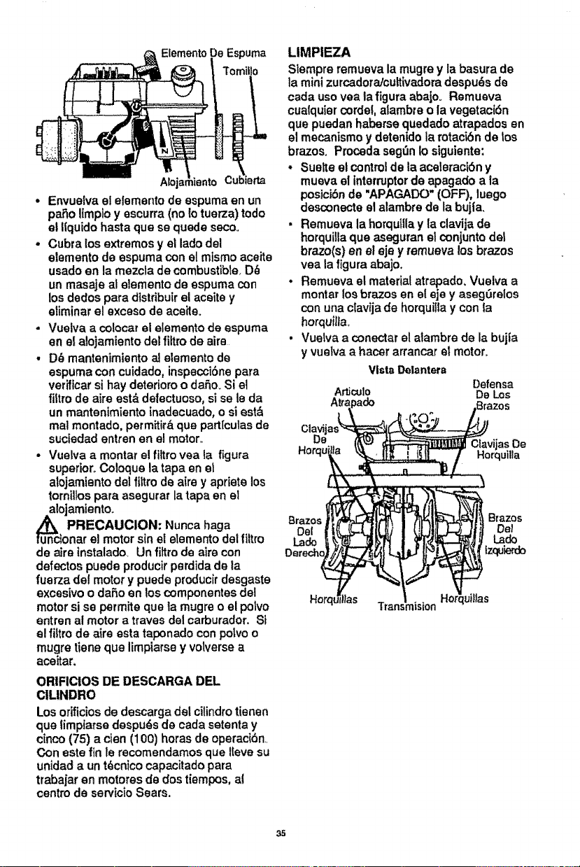
Espuma
• Envueivaeielementodeespumaenun
pareItmptoyescurra(no1otuerza)todo
elliquidohastaquesequedeseco+
- Cubralos extremes yet lade del
elemento de espuma con el mismo aceite
usado en la mezcla de combustible+D_
un masaje al elemento de espuma con
los dedos pare dtstrtbuir el aceite y
efiminar el exceso de aceite+
- Vuelva a colocar el elemento de espuma
en el alojamiento del filtrode aim
• D6 mantenimiento ai elemento de
espuma con cuidado, inspecci6ne para
veriflcar si hay deterioro o dale+ Si el
filtro de aire est& detectuoso, si se le da
un mantenimiento inadecuado, o si est&
mal montado, permitir&que part[culas de
suctedad entrenen el motor+
• Vuelva a montar el _tro vea ia figure
superior+Coloque la tapa en el
alojamiento del fittro de aim y apriete los
tomiltos para asegurar la tape en el
u_nncal°jamient°+
PRECAUCION: Nunca haga
toner el motor sin el elemento del filtro
de aJrelnstalado+ Un fiffro de aire con
defectos puede producir perdida de la
fuerza de! motor y puede producir desgaste
excesivo o dare en los componentes del
motor si se permite qua la mugre o el polvo
entren al motor a traves del carburador. Si
el filtro de aire esta taponado con polvo o
mugre tiene que limpiarse y volverse a
aceitar.
ORIFICIOS DE DESCARGA DEL
ClLINDRO
Los orificiosde descarga del cilindrotienen
que limpiarse despuds de cada setenta y
cinco (75) acien (100) horas de operaci6n+
Con este fin le recomendamos que Iteve su
unidad a un t_cnico capacitado para
trabajar en motores de dos tiempos, al
centre de servicioSears.
LIMPIEZA
Siempre remueva la mugre y labasura de
la minizurcadora/cuttivadoradespu_s de
cada usevea la figura abajo+ Remuava
cualquiercorde!, alambte o la vegetaci6n
que puedan haberse quedado atrapados en
el mecanismo ydeteniclola rotac_6nde toe
brazes+ Proceda seg_n io siguiente:
• Suelte st contro!de la aceleraclbn y
mueva el interrupterde apagado a la
posicibn de "APAGADO" (OFF), luego
desconecte st alambre de la bujla.
• Remueva la horqulllay la clavija de
horquillaque aseguran elconjunto det
braze(s) en el eje y remueva los brazes
yea la figura abajo+
° Remueva el material atrapado+ Vuelva a
reenter los brazes en el eje y asegerelos
con una ctavija de horquifla y con la
horquil_a.
• Vuetva a conectar el atambre de la bujfa
y vuelva a hacer arrancar el motor.
VistaDelantera
Defensa
ArtJc=JIO De Los
Brazes Brazes
De| Del
Lade Lade
Izquierdo
Tmn:
35
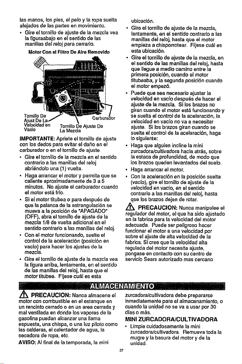
las manos, los pies, el polo y la ropa suelta
alejados de las partes en movimiento°
° Oire ettornillo de ajuste de la mezcla yea
_aflguraabajo en el sentido de las
mani!las del reloj pare cerrar]o.
MotorCon el FittroDe Alto Removtdo
TomiltoDe
ust De
locidadan TornilloDe AjusteDe
Vacio La Mazda
1MPORTANTE: Apriete el tornil!ode ajuste
con los dodos pare evitar el dafio en el
carburador o en el tornilio de ajuste.
• Gire el tornillo de la mezcla en el sentido
contrario alas manillas del reloj
abri_ndolo una (1) vuelta.
. Haga arrancar el motor y permita qua se
caltante aproximadamente de 3 a 5
minutoso No ajuste el carburador cuando
el motor est& fri'o.
• Si el motor titubea o pare despu6s de
qua ta palanca de la estrangulaci6n se
muava ala posiciSn de "APAGADO"
(OFF), abra el torni!lo de ajuste de la
mezcla 1/8 de vuetta adicional en el
sentido contrarioa las manillas del reloj.
. Con el motor funcionando, sue?to el
control de la aceleraci6n (posici6n en
vac|o) para hacer los ajustes de la
mezcla.
• Gire el tornil!ode ajuste de la mezcla yea
la figure arriba, lentamente, en el sentido
de las manilias del reloj, haste qua el
motor titubee, Fljese ou&les esta
ub]caci6n.
. Glre el tornfllode ajuste de la mezcla,
lentamenta, en e?sentido contrario alas
manillas del reloj, hasta qua el motor
empieza achisporrotearo Fl'jese cu&t es
esta ub[caci6m
• Gtre el tornillode ajuste de la mezcla, en
el sentido de las manilias del reloj, hasta
qua llegue a medio camino entre la
primera posic[6n,cuando el motor
titubeaba, y la segunda posiciSncuando
el motor empez6.
. Puede qua sea necesario ajustar la
veloc[dad an vacfodespu6s de hacer el
ajuste de la mezclao Si losbrazos no
girancuando el motor est&funcionando y
se suelta elcontrolde la aceteracibn, la
velocidaden vact'ono va a necesitar
ajusteo Si los brazos giran cuando se
suelta et controlde la aceleracidn, haga
!ostgulente:
• Haga qua alguien incline la mini
zurcadora/cultivadora hacia atr&s, sobre
la estaca de profundidad, de modo qua
losbrazos queden levantados del suelo°
• Haga arrancar el motor.
• Con la aceteracidn en laposici6n sue]ta
(vac[o), gire el torntllode ajuste de la
vetocidaden vacfo, en el sentfdo
contrarioalas manillas del reloj, haste
qua los brazos dejan de rotaro
Z_ PRECAUCION: Nunca manipulee el
reguladordel motor, el qua ha sido ajustado
en la fabrica pare lavetocidad del motor
adecuada. Puede ser peligroso hacer
funcionar el motora una velocidad por
sobre e! ajuste de alta veiocidad de la
fabr_ca. Si cree qua la velocidad alta
regulada del motor necesita ajuste,
pongase en contacto con sucentro de
servicio Sears autorizado mas cercano.
PRECAUClON: Nanca almacene el
motorcon combustible en el estanque en
un rencintocerrado o en un area cerrada y
real ventilada en donde los vapores de la
gasolina puedan alcanzar una llama
espuesta, una chispa,o una luz pilotocomo
las calderas, el ca|entador de agua, la
secadora de ropa, etc,
AVISO: A!final de la temporada, la mini
37
zurcadora/cuttivadoradebe prepararse
inmediatemente pare el almacenamiento, o
cuando la untdad no se va a usar por 30
dlas o m&s.
MINI ZURCADORAJCULTIVADORA
• Limpiecuidadosamente la mini
zurcadora/cultivadora. Remueva toda la
mugre y la basura del motor y de la
unidad_
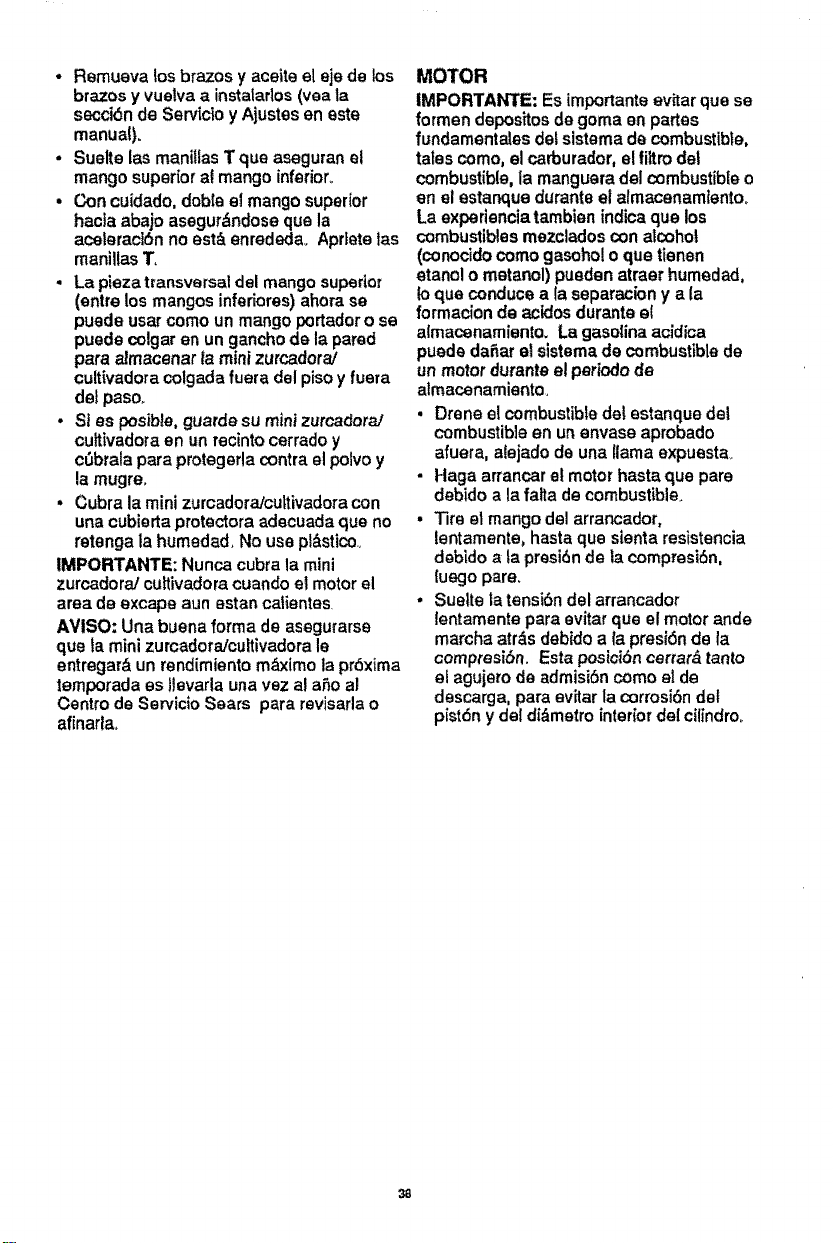
• Remueva los brazos y aceite el eje de los
brazos y vuelva a instatarlos(yea la
secci6n de Servicio y Ajustes en este
manua!).
• Suelte las manillas T qua aseguran et
mango superior af mango inferior_
• Con cuidado, dobla el mango superior
hacla abajo asegur_ndose qua la
aceteraci6n no est& enrededa. Aprtete las
maniUas 1".
. La pieza t_ansversal del mango superior
(entre los mangos inferiores) ahora se
puede usar como un mango portador o se
puede colgar en un gancho de la pared
pare aJmacenar la mini zurcadora/
cultivadora colgada fuera del piso y fuera
det paso_
° Sl es posible, guards su mini zurcadora/
culfivadoraen un recintocerrado y
cSbrala para protegerla contra elpolvo y
la mugre.
• Cubra la mini zurcadora/cuttivadora con
una cubierta protectora adecuada qua no
retenga la humedad, No use pl&stico,
tMPORTANTE: Nunca cubra la mini
zurcadora] cultivadora cuando el motor el
area de excape aun estan catientas,
AVISO: Una buena forma de asegurarse
qua ta mini zurcadora/cultivadora le
entregar& un rendimiento m_imo la pr6xima
temporada es tJevarlaunavez al a6o al
Centro de Servicio Sears para revisarlao
afinarla
MOTOR
IMPORTANTE: Es tmportanteevitar qua se
formen depositosde goma en partes
fundamentales del sistema de combustible,
tates como, el carburador, el filtro del
combustible, la manguera del combustible o
en el estanque durante el almacenamtentoo
La experiencia tambien indicaqua los
combustiblesmezclados con alcohol
(conocidocomo gasohol o qua ttenen
etanol o metanol) pueden atraer humedad,
Io qua conduce ala separacion y ala
formaoion de acidos durante el
almacenamiento. La gasolina acidica
puede da_ar et sistema de combustible de
un motor durante el periodo de
almacenamiento
• Drene el combustibledel estanque del
combustible en unenvase aprobado
afuera, aiejadode una llama expuesta
• Haga arrancar el motor haste que pare
debido a la fatta de combustible.
• Tire el mango del arrancador,
lentamente0 haste qua sienta resistencia
debido ata presi6n de lacompresi6n,
luego pare.
• Suelte la tensi6n del arrancador
lentamente pare evitar qua el motor ande
marcha atr,_s debido a {a presi6n de la
compresi6n Esta posici6ncarter& tanto
et agujero de admisi6n como el de
descarga, pare evitar la corrosi6ndel
pist6ny del di&metrointerior del cilindro_
38
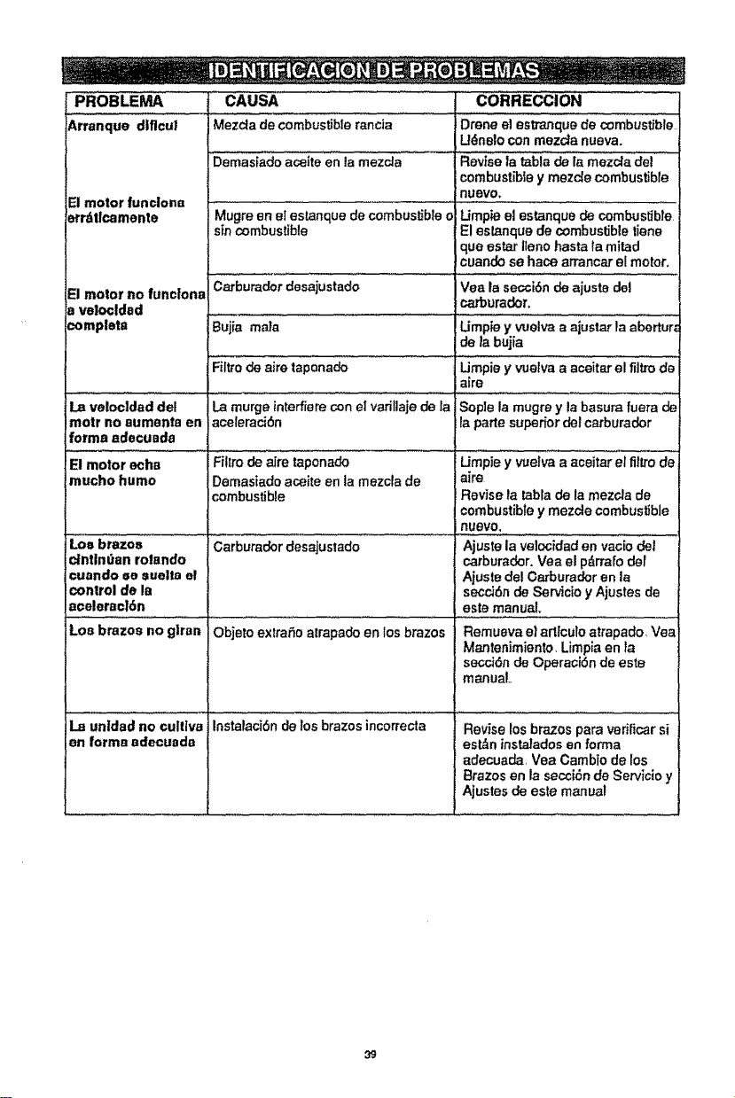
PROBLE_
Arrenque dtflcul
El motor funciona
errdtlcamente
El motor no functona
a velocldad
=ompleta
I CAUSA CORRECCION .........
] Mezcta de combustible rancia Drene el estTanque de combustible
Udnalo con mezda nueva.
Demas{ado a_{te enia mezcla ............. Revise 1atabia de i_ mezc_a del
combustible y mezc{e combustible
nUevo,
Mugre en el estanque de combustible o Umpie el estanque de combustible
sin combustible El eslanque de combustible tiene
que ester Ileno haste la mired
cuando se hace arrancar el motor.
Carburador desajustado Vea la secciSn de ajuste del
_ura_r.
Bujia male Umpie y wolva a ajustar la abertur_
de la bujia
Filtro de airs taponado
La velocldad del
motr no aumenta en
forma ec|eouada
El motor echa iFilZrode aire taponado
mucho humo
Los brazos
c_ntlndan rotando
cuando se suelta el
control de la
ecelerac16n
Los bmzoe no giran
iLa murge interfiere con el varillaje de la
acelemciSn
!Demasiado acoite en la mezcla de
combustible
Carburadordesajustado
c ......
Objsto extraSo alrapado en los brazos
Instalacidn de los brazos incortectaLa unldad nocultlve
en formsedecuada
Umpie y vuetva a aceitar el filtzode
alre
Sople la mugre y la basura fuera de
la parts superfor del carburador
Umpie y vue]va a aceitar el fii_o de
airs
Revise la tabla de la mezcla de
combustible y mezcle combustible
nUeVO,
Ajuste la velocidad en ratio _i
carburador. Vea el p_,rralo del
Ajuste del C,arburador en la
seccJ6nde Servicio y Ajustes de
este manual.
Remueva el erttculo atrapado Vea
Mantanimiento, Limpia en }a
secr,J6n de OperaoiSn de este
manual.
Revise los brazos para verificar si
est_n insta]adosen forrna
adecuada, Vea Cambio de los
Brazos en la secci&n de Servicio y
Ajustes de este manual
39

For the repair or replacement parts you
need delivered directly to your home
Call 7 am-7 pm, 7 days a week
1-800-366-PART
(1-800-366-7278)
Para ordenar piezas con entrega
a domicilio -1-800-659-7084
For in-house major brand repair service
Call 24 hours a day, 7 days a week
1-800-4-REPAIR
(1-800-473-7247)
Para pedlr ser-¢icio de reparacibn a
domicilio - 1-800-676-5811
For the location of a Sears Parts and
Repair Center in your area
Call 24 hours a day, 7 days a week
1-800-488-1222
For information on purchasing a Sears
Maintenance Agreement or to lnqulre
about an existing Agreement
Call 9 am -5pm, Monday-Saturday
1-800-827-6655
When requesting service or ordering
parts, always provide the following
information:
• Product Type • Part Number
• Model Number • Part DescripUon
America'sRepairSpecialists
Printedtn U,S_A..