Operator's Manual
CRRFTSMRIq
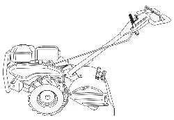
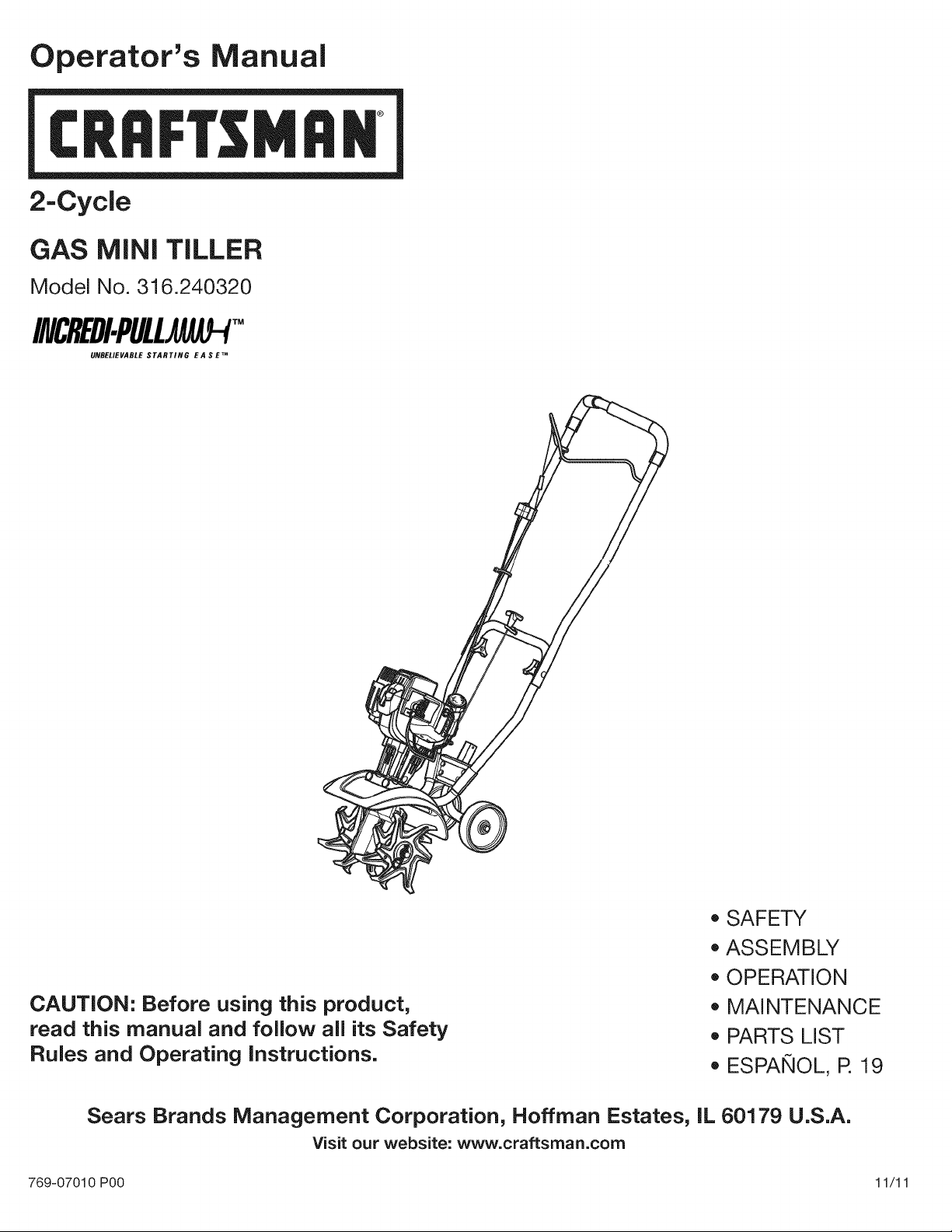
2-Cycle
GAS MINI TILLER
Model No. 316.240320
INCREDI.PULU AU-P
UNBELIEVABLE STARTING E A S E TM
CAUTION: Before using this product,
read this manual and foJJow aJJits Safety
RuJes and Operating instructions.
• SAFETY
ASSEMBLY
OPERATION
MAINTENANCE
PARTS LIST
ESPANOL, R 19
Sears Brands Management Corporation, Noffman Estates, IL 60179 U.S.A.
Visit our website: www.craftsman.com
769-07010 P00 11/11
TABLEOFCONTENTS
Safety............................................... 2
Warranty............................................. 5
KnowYourUnit........................................ 6
Specifications......................................... 6
Assembly............................................. 7
OilandFuel........................................... 8
StartingandStopping................................... 9
Operation............................................ 10
Maintenance......................................... 11
CleaningandStorage.................................. 13
Troubleshooting....................................... 14
RepairProtectionAgreements........................... 15
PartsList............................................ 38
ServiceNumbers.............................. BackCover
Allinformation,illustrationsandspecificationsinthismanualarebased
onthelatestproductinformationavailableatthetimeofprinting.We
reservetherighttomakechangesatanytimewithoutnotice.
Thepurposeofsafetysymbolsistoattractyourattentionto
possibledangers.Thesafetysymbols,andtheirexplanations,
deserveyourcarefulattentionandunderstanding.Thesafety
warningsdonotbythemselveseliminateanydanger.The
instructionsorwarningstheygivearenotsubstitutesforproper
accidentpreventionmeasures.
SYMBOL MEANING
DANGER: Signals an EXTREME hazard.
Failure to obey a safety DANGER signal WILL result in
serious injury or death to yourself or to others.
WARNING: Signals a SERIOUS hazard.
Failure to obey a safety WARNING signal CAN result in
serious injury to yourself or to others.
CAUTION: Signals a MODERATE hazard.
Failure to obey a safety CAUTION signal MAY result in
property damage or injury to yourself or to others.
NOTE: Advises you of information or instructions vital to the
operation or maintenance of the equipment.
SPARK ARRESTOR NOTE
NOTE: For users on U.S. Forest Land and in the states of
California, Maine, Oregon and Washington. All U.S. Forest Land
and the state of California (Public Resources Codes 4442 and
4443), Oregon and Washington require, by law that certain internal
combustion engines operated on forest brush and/or grass-covered
areas be equipped with a spark arrestor, maintained in effective
working order, or the engine be constructed, equipped and
maintained for the prevention of fire. Check with your state or local
authorities for regulations pertaining to these requirements. Failure
to follow these requirements could subject you to liability or a fine.
This unit is factory equipped with a spark arrestor. Replacement
requires Muffler Assembly Part #753-06792, installed at a Sears
Parts & Repair Service Center.
CALIFORNIA PROPOSITION 65
WARNING: Engine exhaust, some of its constituents and
certain finished components contain or emit chemicals known
to the State of California to cause cancer and birth defects or
other reproductive harm. Wash hands after handling.
Read the operator's manual and follow all warnings and safety
instructions. Failure to do so can result in serious injury to the
operator and/or bystanders.
READ ALL iNSTRUCTiONS BEFORE OPERATING
o
o
o
o
o
o
o
o
WARNING: When using the unit, all safety rules must be
followed. Please read these instructions before operating
the unit in order to ensure the safety of the operator and any
bystanders. Please keep these instructions for later use.
Read the instructions carefully. Be familiar with the controls and
proper use of the unit.
Do not operate this unit when tired, ill or under the influence of
alcohol, drugs or medication.
Children and teens under the age of 15 must not use the unit,
except for teens guided by an adult.
All guards and safety attachments must be installed properly
before operating the unit.
Inspect the unit before use. Replace damaged parts. Check for
fuel leaks. Make sure all fasteners are in place and secure.
Replace parts that are cracked, chipped, or damaged in any
way. Do not operate the unit with loose or damaged parts.
Carefully inspect the area before starting the unit. Remove all
debris and hard or sharp objects such as glass, wire, etc.
Be aware of the risk of injury to the head, hands and feet.
Clear the area of children, bystanders and pets; keep them
outside a 50-foot (15 m) radius, at a minimum. Even then, they
are still at risk from thrown objects. Encourage bystanders to
wear eye protection. If you are approached, stop the unit
immediately.
Squeeze the throttle control and check that it returns
automatically to the idle position. Make all adjustments or
repairs before using the unit.
SAFETY WARNINGS FOR GAS UNITS
_WARNING: Gasoline is highly flammable and its vapors j
can explode if ignited. Take the following precautions:
• Store fuel only in containers specifically designed and approved
for the storage of such materials.
Always stop the engine and allow it to cool before filling the
tank. Never remove the fuel tank cap or add fuel when the
engine is hot. Always loosen the fuel tank cap slowly to relieve
any pressure in the tank before fueling.
Always mix and add fuel in a clean, well-ventilated outdoor area
where there are no sparks or flames. DO NOT smoke.
Never operate the unit without the fuel cap securely in place.
Avoid creating a source of ignition for spilled fuel. Wipe up any
spilled fuel from the unit immediately, before starting the unit.
Move the unit at least 30 ft. (9.1 m) from the fueling source and
site before starting the engine. DO NOT smoke.
Never start or run the unit inside a closed room or building.
Breathing exhaust fumes can kill. Operate this unit only in a well
ventilated outdoor area.
WHILE OPERATING
Wear safety glasses or goggles that meet ANSi Z87.1-1989
standards and are marked as such. Wear ear/hearing protection
when operating this unit. Wear a face or dust mask if the
operation is dusty.
Wear heavy long pants, boots, gloves and a long sleeve shirt. Do
not wear loose clothing, jewelry, short pants, sandals or go
barefoot. Secure hair above shoulder level.
This unit has a clutch. The tines remain stationary when the
engine is idling. If they do not, take the unit to a Sears or other
qualified service dealer for an adjustment.
Be sure the tines are not in contact with anything before starting
the unit.
Use the unit only in daylight or good artificial light.
Avoid accidental starting. Be in the starting position whenever
pulling the starter rope. The operator and unit must be in a stable
position while starting. Refer to Starting and Stopping.
Use the right tool. Only use this tool for its intended purpose.
Use extreme caution when reversing or pulling the unit towards you.
Do not overreach. Always keep proper footing and balance. Take
extra care when working on steep slopes or inclines.
Always hold the unit with both hands when operating. Keep a
firm grip on both handles or grips.
Keep hands, face, and feet away from all moving parts. Do not
touch or try to stop the tines when they are rotating.
Do not touch the engine or muffler. These parts get extremely hot
from operation, even after the unit is turned off.
Do not operate the engine faster than the speed needed to cultivate.
Do not run the engine at high speed when you are not cultivating.
Always stop the engine when cultivating is delayed or when walking
from one cultivating location to another.
If you strike or become entangled with a foreign object, stop the
engine immediately and check for damage. Do not operate
before repairing damage. Do not operate the unit with loose or
damaged parts.
Turn the engine to off and disconnect the spark plug for
maintenance or repair.
Use only original equipment manufacturer (OEM) replacement
parts and accessories for this unit, as listed in the Parts List
section of this manual. Use of any other parts or accessories
could lead to serious injury to the user, or damage to the unit,
and void the warranty.
Keep the unit clean of vegetation and other materials that may
become lodged between the tines and guard.
To reduce fire hazard, replace a faulty muffler and spark arrestor.
Keep the engine and muffler free from grass, leaves, excessive
grease or carbon build up.
OTHER SAFETY WARNINGS
Never store the unit with fuel in the tank, inside a building where
fumes may reach an open flame (pilot lights, etc.) or sparks
(switches, electrical motors, etc.).
Allow the engine to cool before storing or transporting. Be sure
to secure the unit while transporting.
Store the unit in a dry place, secured or at a height to prevent
unauthorized use or damage. Keep out of the reach of children.
Never douse or squirt the unit with water or any other liquid.
Keep handles dry, clean and free from debris. Clean after each
use, see Cleaning and Storage instructions.
Clean tines with a household cleaner to remove any gum
buildup. Oil the tines with machine oil to prevent rust.
Keep these instructions. Refer to them often and use them to
instruct other users. If you loan this unit to others, also loan
them these instructions.
SAVE THESE iNSTRUCTiONS
3
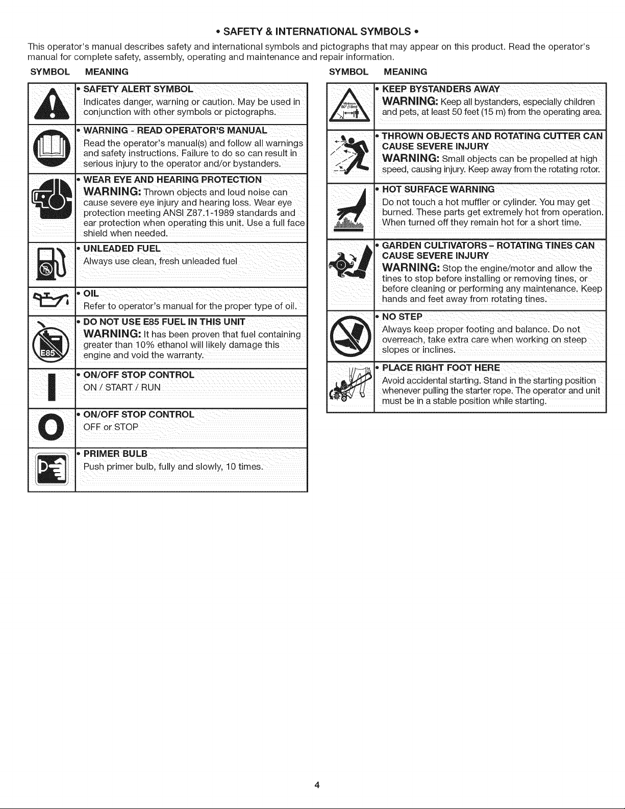
o SAFETY & iNTERNATiONAL SYMBOLS o
This operator's manual describes safety and international symbols and pictographs that may appear on this product. Read the operator's
manual for complete safety, assembly, operating and maintenance and repair information.
SYMBOL MEANING SYMBOL MEANING
_ • SAFETY ALERT SYMBOL
Indicates danger, warning or caution. May be used in
conjunction with other symbols or pictographs.
'_ WARNING - READ OPERATOR'S MANUAL
_]J J J[_ Read the operator's manual(s) and follow all warnings
and safety instructions. Failure to do so can result in
serious injury to the operator and/or bystanders.
4t _ - WEAR EYE AND HEARING PROTECTION
WARNING: Thrown objects and loud noise can
_! cause severe eye injury and hearing loss. Wear eye
protection meeting ANSI Z87.1-1989 standards and
. ear protection when operating this unit. Use a full face
shield when needed.
m _ • UNLEADED FUEL
_ Always use clean fresh unleaded fuel
.aUl
OIL
Refer to operator's manual for the proper type of oil.
• DO NOT USE E85 FUEL iN THIS UNiT
/_ I WARNING: It has been proven that fuel containing
(_ I greater than 10% ethanol will likely damage this
\_ I engine and void the warranty.
| I"ON/OFFSTOPCONTROL
| I
• ON/OFF STOP CONTROL
U . OgForSTOP
_ PRIMER BULB
_] Push prmerbulb fu yandsowly 10tmes
, EEP BYSTANDERS AWAY
WARNING: Keep aii bystanders, espeCiallY Chi!dien
and Pets, at least 50 feet (!5 m) from the operating area.
_71_ _THROWN OBJECTS AND ROTATING CUTTER CAN
/ :-_L_ CAUSE SEVERE INJURY
_< WARNING: small objects can be pr0peiied at high
speed, causing injury,Keep away from the rotating rotor.
, H0T SURFACE WARNING
Don0t touch a hot muffler or cyl!nder;You may get
burned. These parts get extremely hot from operation.
;_lllll/ll_l_ll),. When turned off they remain hot for a short t me.
_ GARDEN CULTIVATORS _ ROTATING TINES CAN
CAUSE SEVERE iNJURY
WARNING: St0p the engine/m0t0r and
tines to stop before installing Or removing tines, or
before cleaning Or performing any maintenancel Keep
hands and feet away from rotating tines;
@ _ NOSTEP
AlwaYS keep proper footing and balance: DO not
Overreach, take extra care when working on Steep
slopes or inclines.
, PLACER GHTFooTHERE
[ __-! _ Avoid accidental starting. Stand in the starting position
€_ whenever pulling the starter rope: The operator and Unit
"_'_- . must be in a stable position while starting.
CRAFTSMANTWO YEAR FULL WARRANTY
FOR TWO YEARS from the date of purchase, this product is warranted against any defects in material or workmanship. A defective product
will receive free repair or replacement if repair is unavailable.
For warranty coverage details to obtain free repair or replacement, visit the web site: www.craftsman.com
This warranty covers ONLY defects in material and workmanship. Warranty coverage does NOT include:
• Expendable items that can wear out from normal use within the warranty period, such as blades, tines or belts.
Product damage resulting from user attempts at product modification or repair or caused by product accessories.
Repairs necessary because of accident or failure to operate or maintain the product according to all supplied instructions.
Preventive maintenance, or repairs necessary due to improper fuel mixture, contaminated or stale fuel.
This warranty is void if this product is ever used while providing commercial services or if rented to another person.
This warranty gives you specific legal rights, and you may also have other rights which vary from state to state.
Sears Brands Management Corporation, Hoffman Estates, IL 60179
FOR IN-WARRANTY SAFETY, OPERATION OR MAINTENANCE QUESTIONS, OR TO ORDER PARTS AND SCHEDULE
SERVICE, CALL 1=800=4=MY=HOME®.
5
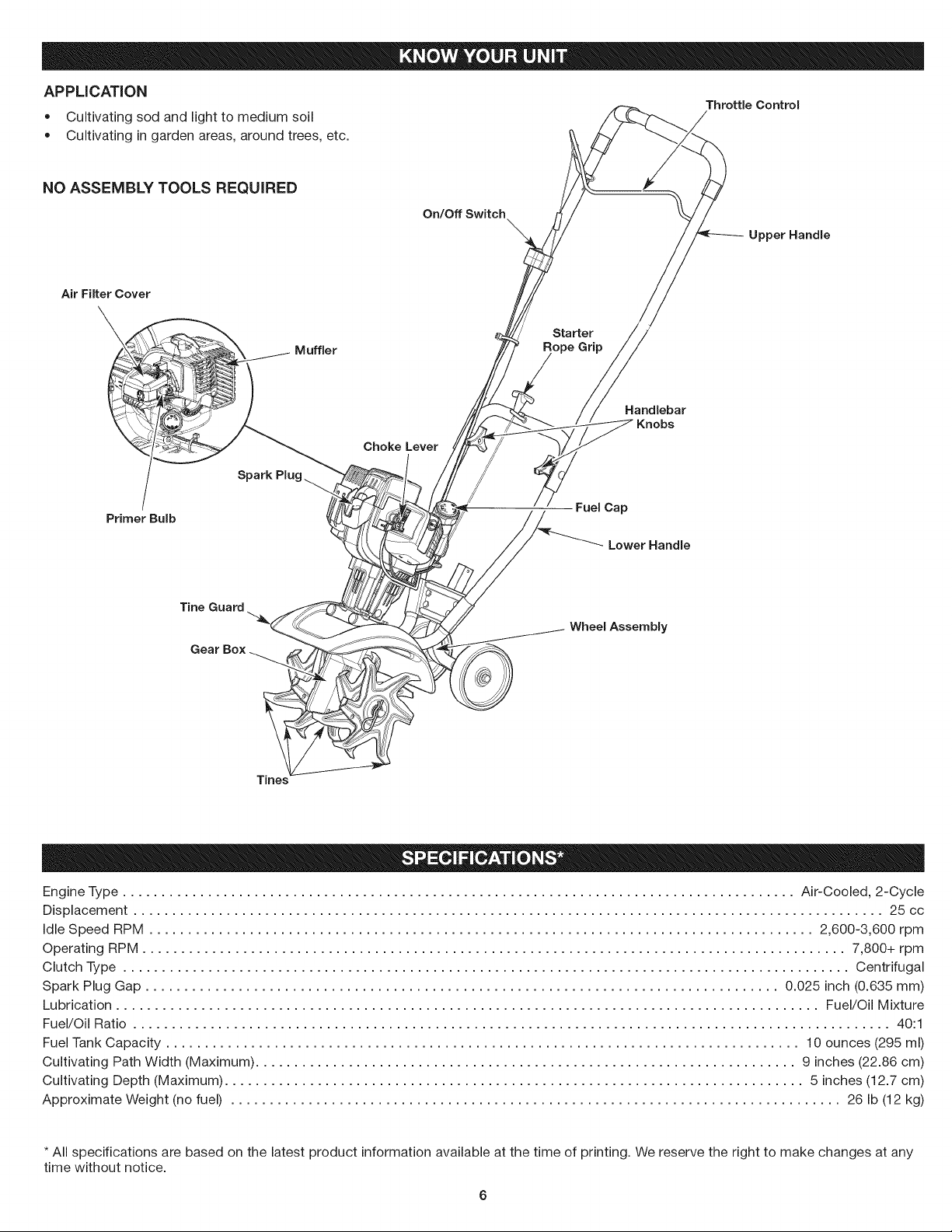
APPLiCATiON
Throttle Control
• Cultivating sod and light to medium soil
Cultivating in garden areas, around trees, etc.
NO ASSEMBLY TOOLS REQUIRED
On/Off Switch
Upper Handle
Air Filter Cover
Starter
Muffler ope Grip
Choke Lever
Handlebar
Knobs
Primer Bulb
FueICap
LowerHandle
Tine Guard
Wheel Assembly
Tines
Engine Type ....................................................................................... Air-Cooled, 2-Cycle
Displacement ................................................................................................. 25 cc
Idle Speed RPM ...................................................................................... 2,600-3,600 rpm
Operating RPM ........................................................................................... 7,800+ rpm
Clutch Type .............................................................................................. Centrifugal
Spark Plug Gap .................................................................................. 0.025 inch (0.635 mm)
Lubrication ........................................................................................... Fuel/Oil Mixture
Fuel/Oil Ratio .................................................................................................. 40:1
Fuel Tank Capacity .................................................................................. 10 ounces (295 ml)
Cultivating Path Width (Maximum) ...................................................................... 9 inches (22.86 cm)
Cultivating Depth (Maximum) ........................................................................... 5 inches (12.7 cm)
Approximate Weight (no fuel) ............................................................................... 26 Ib (12 kg)
* All specifications are based on the latest product information available at the time of printing. We reserve the right to make changes at any
time without notice.
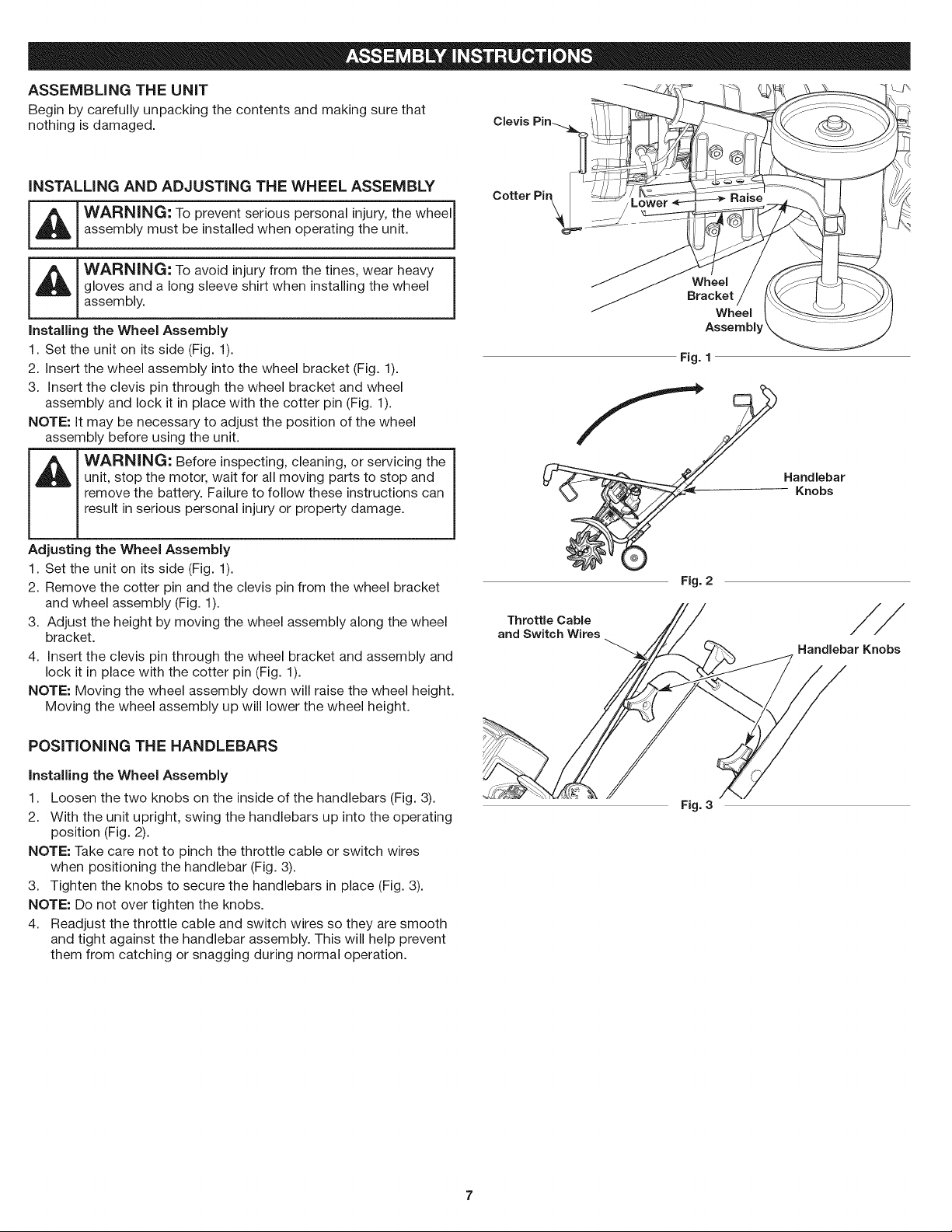
ASSEMBLINGTHE UNiT _-.'_
Begin by carefully unpacking the contents and making sure that
nothing is damaged.
INSTALLING AND ADJUSTING THE WHEEL ASSEMBLY
_ WARNING: To prevent serious personal injury, the wheelj
assembly must be installed when operating the unit.
WARNING: To avoid injury from the tines, wear heavy
gloves and a long sleeve shirt when installing the wheel
assembly.
Installing the Wheel Assembly
1. Set the unit on its side (Fig. 1).
2. Insert the wheel assembly into the wheel bracket (Fig. 1).
3. Insert the clevis pin through the wheel bracket and wheel
assembly and lock it in place with the cotter pin (Fig. 1).
NOTE: It may be necessary to adjust the position of the wheel
assembly before using the unit.
WARNING: Before inspecting, cleaning, or servicing the
unit, stop the motor, wait for all moving parts to stop and
remove the battery. Failure to follow these instructions can
result in serious personal injury or property damage.
Adjusting the Wheel Assembly
1. Set the unit on its side (Fig. 1).
2. Remove the cotter pin and the clevis pin from the wheel bracket
and wheel assembly (Fig. 1).
3. Adjust the height by moving the wheel assembly along the wheel
bracket.
4. Insert the clevis pin through the wheel bracket and assembly and
lock it in place with the cotter pin (Fig. 1).
NOTE: Moving the wheel assembly down will raise the wheel height.
Moving the wheel assembly up will lower the wheel height.
POSiTiONiNG THE HANDLEBARS
installing the Wheel Assembly
1. Loosen the two knobs on the inside of the handlebars (Fig. 3).
2. With the unit upright, swing the handlebars up into the operating
position (Fig. 2).
NOTE: Take care not to pinch the throttle cable or switch wires
when positioning the handlebar (Fig. 3).
3. Tighten the knobs to secure the handlebars in place (Fig. 3).
NOTE: Do not over tighten the knobs.
4. Readjust the throttle cable and switch wires so they are smooth
and tight against the handlebar assembly. This will help prevent
them from catching or snagging during normal operation.
Cotter Pir_
Wheel
Bracket
Wheel
Assembb
Fig. 1
Fig. 2
Handlebar
Knobs
Throttle Cable
and Switch Wires
Handlebar Knobs
Fig. 3
OiL AND FUEL MiXiNG iNSTRUCTiONS
FUELING THE UNiT
The use of old and/or improperly mixed fuel is the most common cause
of performance problems. Use only fresh, clean unleaded gasoline.
Follow the instructions carefully for the proper gasoline/oil mixture.
Definition of Blended Fuels
Today's fuels are often a blend of gasoline and oxygenates such as
ethanol, methanol or MTBE (ether). Alcohol-blended fuel absorbs
water. As little as 1% water in the fuel can make fuel and oil
separate, forming acids when stored. ALWAYS use fresh fuel (less
than 30 days old).
NOTE: Dispose of old fuel according to federal, state and local
regulations.
Using Blended Fuels
If using a blended fuel:
• Always use the fresh fuel mix explained in your operator's manual
Use the fuel additive STA-BIL® or an equivalent
Always agitate the fuel mix before fueling the unit
Drain the tank and run the engine dry before storing the unit
_ WARNING: DO NOT USE E85 FUEL IN THiS UNIT. It |
I
has been proven that fuel containing greater than 10%
1
ethanol will likely damage this engine and void the warranty.
Using Fuel Additives
The bottle of 2-cycle oil provided with this unit contains a fuel
additive to help inhibit corrosion and minimize gum deposits.
Always use the brand of 2-cycle oil that came with this unit. If this is
unavailable, use a 2-cycle oil designed for air-cooled engines and
mix it with a fuel additive, such as STA-BIL Fuel Stabilizer or an
equivalent. Add 0.8 oz. (23 ml) of fuel additive per gallon of fuel,
according to the instructions on the container. NEVER add fuel
additives directly to the unit's fuel tank.
WARNING: Gasoline is extremely flammable. Ignited
vapors may explode. Always stop the engine and allow it
to cool before filling the fuel tank. Do not smoke while
filling the tank. Keep sparks and open flames at a distance
from the area.
WARNING: Remove the fuel cap slowly to avoid injury
from fuel spray. Never operate the unit without the fuel cap
securely in place.
WARNING: Add fuel in a clean, well ventilated outdoor
area. Wipe up any spilled fuel immediately. Avoid creating
a source of ignition for spilled fuel. Do not start the engine
until fuel vapors dissipate.
1. Position the unit with the fuel cap facing up.
2. Remove the fuel cap.
3. Place the fuel container spout into the fill hole on the fuel tank
and fill the tank.
NOTE: Do not overfill the tank.
4. Wipe up any fuel that may have spilled.
5. Reinstall the fuel cap.
6. Move the unit at least 30 ft. (9.1 m) from the fuel container and
the fueling site before starting the engine.
Mixing the Fuel
NOTE: This unit comes with a 3.2 oz. bottle of 2-cycle oil. To obtain
the correct fuel mixture described below, pour the entire bottle
into one gallon of unleaded gasoline.
CAUTION: For proper engine operation and maximum
reliability, pay strict attention to the gasoline and oil mixing
instructions on the 2-cycle oil bottle. Using improperly
mixed fuel can severely damage the engine.
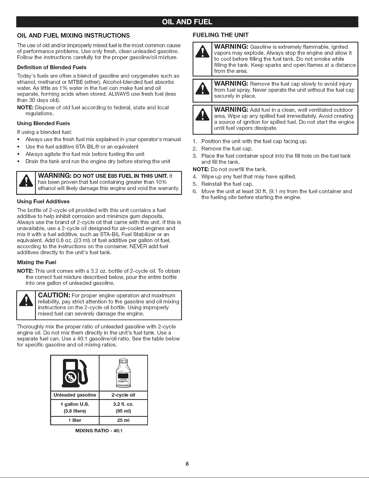
Thoroughly mix the proper ratio of unleaded gasoline with 2-cycle
engine oil. Do not mix them directly in the unit's fuel tank. Use a
separate fuel can. Use a 40:1 gasoline/oil ratio. See the table below
for specific gasoline and oil mixing ratios.
Unleaded gasoline
1 gallon U.S.
(3.8 liters}
1 liter
2=cycleoil
3.2 ft. oz.
(95 ml)
25 rnl
MIXING RATIO = 40:1
I_IL I WARNING: Operate this unit only in a well-ventilated
!
outdoor area. Carbon monoxide exhaust fumes can be
lethal in a confined area.
_L_____[ ARNING: Avoid accidentally starting the unit. To avoid
serious injury, the operator and the unit must be in a stable
J
position when pulling the starter rope (Fig. 7).
STARTING INSTRUCTIONS
1. Mix gasoline with oil. Refer to Oil and Fuel Mixing Instructions.
2. Fill the fuel tank. Refer to Fueling the Unit.
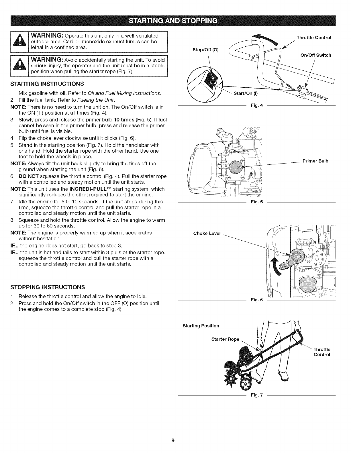
NOTE: There is no need to turn the unit on. The On/Off switch is in
the ON (I) position at all times (Fig. 4).
3. Slowly press and release the primer bulb 10 times (Fig. 5). If fuel
cannot be seen in the primer bulb, press and release the primer
bulb until fuel is visible.
4. Flip the choke lever clockwise until it clicks (Fig. 6).
5. Stand in the starting position (Fig. 7). Hold the handlebar with
one hand. Hold the starter rope with the other hand. Use one
foot to hold the wheels in place.
NOTE: Always tilt the unit back slightly to bring the tines off the
ground when starting the unit (Fig. 6).
6. DO NOT squeeze the throttle control (Fig. 4). Pull the starter rope
with a controlled and steady motion until the unit starts.
NOTE: This unit uses the INCREDI-PULL TM starting system, which
significantly reduces the effort required to start the engine.
7. Idle the engine for 5 to 10 seconds. If the unit stops during this
time, squeeze the throttle control and pull the starter rope in a
controlled and steady motion until the unit starts.
8. Squeeze and hold the throttle control. Allow the engine to warm
up for 30 to 60 seconds.
NOTE: The engine is properly warmed up when it accelerates
without hesitation.
IF... the engine does not start, go back to step 3.
IF... the unit is hot and fails to start within 3 pulls of the starter rope,
squeeze the throttle control and pull the starter rope with a
controlled and steady motion until the unit starts.
Stop/Off (O)
Start/On (I)
Fig. 4
Fig. 5
Choke Lever
Throttle Control
On/Off Switch
Primer Bulb
STOPPING INSTRUCTIONS
1. Release the throttle control and allow the engine to idle.
2. Press and hold the On/Off switch in the OFF (O) position until
the engine comes to a complete stop (Fig. 4).
Fig. 6
Starting Position
Starter Ro
Throttle
Control
Fig. 7
9
WARNING: Dress properly to reduce the risk of injury
when operating this unit. Do not wear loose clothing or
jewelry. Wear eye and ear/hearing protection. Wear heavy
long pants, boots and gloves. Do not wear short pants,
sandals or operate barefoot.
OPERATING TiPS
1. Move the cultivator to the work area prior to starting the engine.
Refer to Moving the Unit.
L_J AUTION: To prevent serious personal injury, never
pick-up or carry the unit while the engine is running.
2. Start the unit as described in the Starting Instructions.
3. With the tines off the ground, squeeze the throttle control to
increase the engine speed.
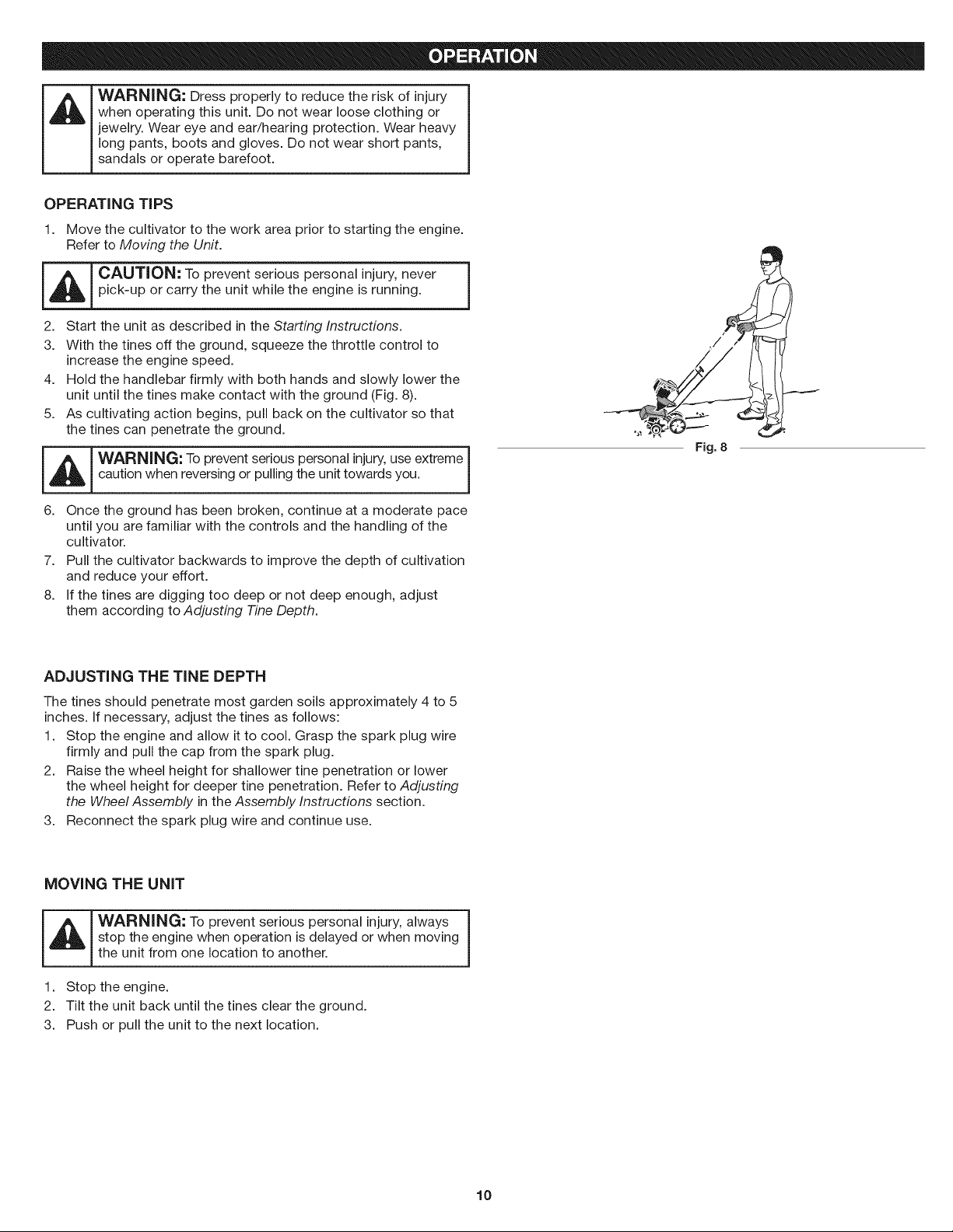
4. Hold the handlebar firmly with both hands and slowly lower the
unit until the tines make contact with the ground (Fig. 8).
5. As cultivating action begins, pull back on the cultivator so that
the tines can penetrate the ground.
]
7.
8.
_ ARNING: To prevent serious personal injury,use extreme
caution when reversing or pulling the unit towards you.
J
6. Once the ground has been broken, continue at a moderate pace
until you are familiar with the controls and the handling of the
cultivator.
Pull the cultivator backwards to improve the depth of cultivation
and reduce your effort.
If the tines are digging too deep or not deep enough, adjust
them according to Adjusting -FineDepth.
Fig. 8
ADJUSTING THE TINE DEPTH
The tines should penetrate most garden soils approximately 4 to 5
inches. If necessary, adjust the tines as follows:
1. Stop the engine and allow it to cool. Grasp the spark plug wire
firmly and pull the cap from the spark plug.
2. Raise the wheel height for shallower tine penetration or lower
the wheel height for deeper tine penetration. Refer to Adjusting
the Wheel Assembly in the Assembly Instructions section.
3. Reconnect the spark plug wire and continue use.
MOVING THE UNiT
stop the engine when operation is delayed or when moving
the unit from one location to another.
1. Stop the engine.
2. Tilt the unit back until the tines clear the ground.
3. Push or pull the unit to the next location.
10
WARNING: To prevent serious injury, never perform
maintenance or repairs while the unit is running. Always
allow the unit to cool before servicing or repairing the unit.
Disconnect the spark plug wire to prevent the unit from
starting accidentally.
MAINTENANCE SCHEDULE
Perform these required maintenance procedures at the frequency
stated in the table. These procedures should also be a part of any
seasonal tune-up.
NOTE: Some maintenance procedures may require special tools or
skills. If unsure about these procedures, take the unit to a Sears
or other qualified service dealer. Call 1-800-4-MY-HOME for
more information.
NOTE: Maintenance, replacement, or repair of the emission control
devices and system may be performed by a Sears or other qualified
service dealer. Call 1=800-4-MY-HOME for more information.
NOTE: Please read the California/EPA statement that came with the
unit for a complete listing of terms and coverage for the
emissions control devices, such as the spark arrestor, muffler,
carburetor, etc.
FREQUENCY MAINTENANCE REQUIRED
Every 10 hours Clean and re-oil the air filter. Refer to
Maintaining the Air Filter.
Every 25 hours Check the spark plug condition and gap. Refer
to Maintaining the Spark Plug.
TINE REMOVAL AND REPLACEMENT
__ l WARNJNG: To prevent serious personal injury, always j
wear heavy gloves when handling the tines.
NOTE: All installation instructions are explained from the operating
position.
All 4 tines should be replaced at the same time because they will
wear evenly through normal use. Work on one side at a time.
1. Stop the engine and allow it to cool. Grasp the spark plug wire
firmly and pull the cap from the spark plug.
2. Lay the cultivator back on a flat level surface with the handles
touching the ground so that the cultivator is in a horizontal position.
NOTE: It may be necessary to wash any dirt off the tines and shaft
for easier tine removal.
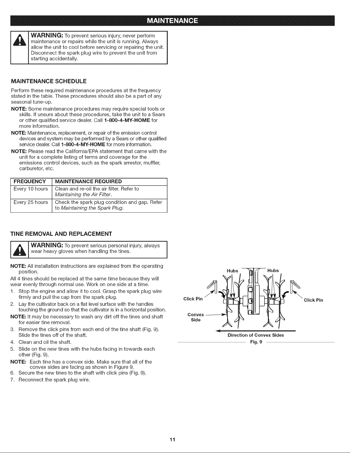
3. Remove the click pins from each end of the tine shaft (Fig. 9).
Slide the tines off of the shaft.
4. Clean and oil the shaft.
5. Slide on the new tines with the hubs facing in towards each
other (Fig. 9).
NOTE: Each tine has a convex side. Make sure that all of the
convex sides are facing as shown in Figure 9.
6. Secure the new tines to the shaft with click pins (Fig. 9).
7. Reconnect the spark plug wire.
Click Pin
Convex
Side
Hubs
' Hubs
Click Pin
Direction of Convex Sides
Fig. 9
11
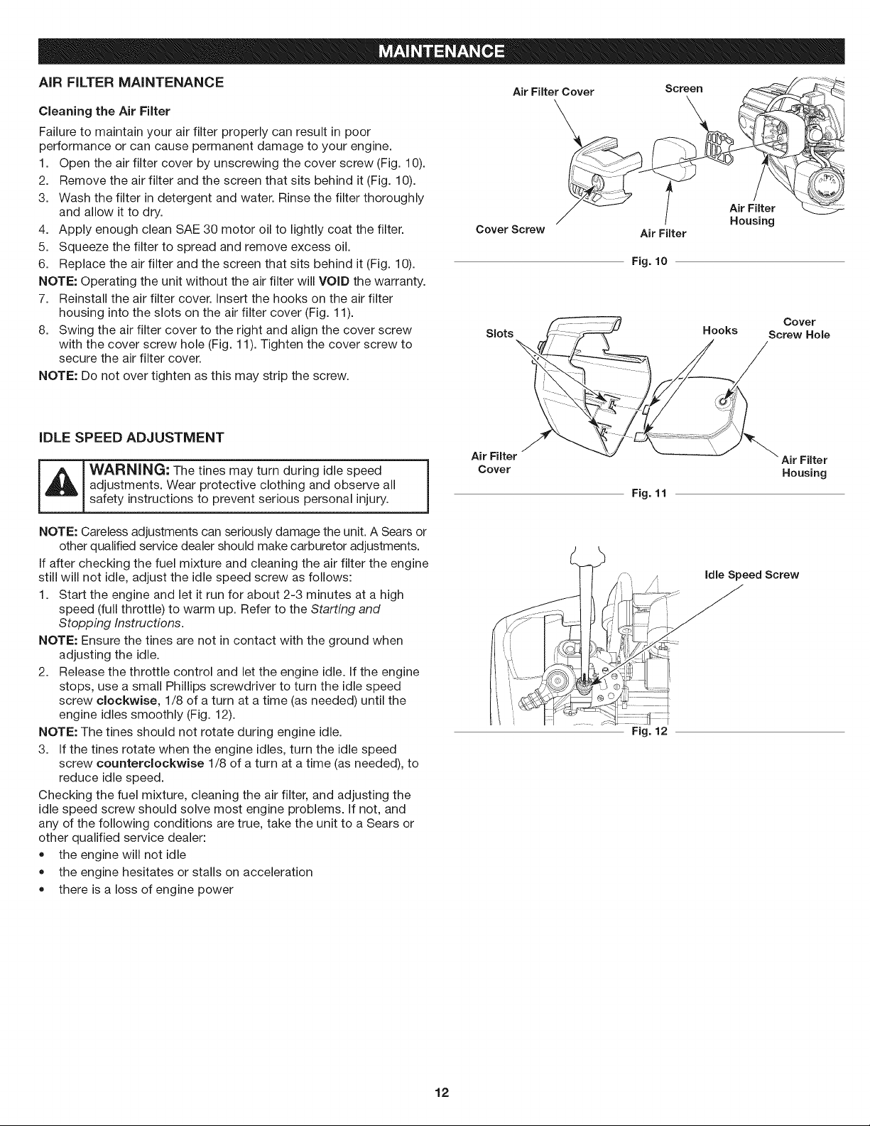
AiR FILTER MAINTENANCE
Cleaning the Air Filter
Failure to maintain your air filter properly can result in poor
performance or can cause permanent damage to your engine.
1. Open the air filter cover by unscrewing the cover screw (Fig. 10).
2. Remove the air filter and the screen that sits behind it (Fig. 10).
3. Wash the filter in detergent and water. Rinse the filter thoroughly
and allow it to dry.
4. Apply enough clean SAE 30 motor oil to lightly coat the filter.
5. Squeeze the filter to spread and remove excess oil.
6. Replace the air filter and the screen that sits behind it (Fig. 10).
NOTE: Operating the unit without the air filter will VOiD the warranty.
7. Reinstall the air filter cover, insert the hooks on the air filter
housing into the slots on the air filter cover (Fig. 11).
8. Swing the air filter cover to the right and align the cover screw
with the cover screw hole (Fig. 11). Tighten the cover screw to
secure the air filter cover.
Air Filter Cover
\
/
Cover Screw Air Filter
Slots
Screen
Fig. 10
Air Filter
Housing
Cover
Hooks Screw Hole
NOTE: Do not over tighten as this may strip the screw.
iDLE SPEED ADJUSTMENT
Air Filter
_ WARNING: The tines may turn during idle speed _ Cover
adjustments. Wear protective clothing and observe all
1
safety instructions to prevent serious personal injury.
NOTE: Careless adjustments can seriously damage the unit. A Sears or
other qualified service dealer should make carburetor adjustments.
If after checking the fuel mixture and cleaning the air filter the engine
still will not idle, adjust the idle speed screw as follows:
1. Start the engine and let it run for about 2-3 minutes at a high
speed (full throttle) to warm up. Refer to the Starting and
Stopping Instructions.
NOTE: Ensure the tines are not in contact with the ground when
adjusting the idle.
2. Release the throttle control and let the engine idle. If the engine
stops, use a small Phillips screwdriver to turn the idle speed
screw clockwise, 1/8 of a turn at a time (as needed) until the
engine idles smoothly (Fig. 12).
NOTE: The tines should not rotate during engine idle.
3. If the tines rotate when the engine idles, turn the idle speed
screw counterclockwise 1/8 of a turn at a time (as needed), to
reduce idle speed.
Checking the fuel mixture, cleaning the air filter, and adjusting the
idle speed screw should solve most engine problems. If not, and
any of the following conditions are true, take the unit to a Sears or
other qualified service dealer:
• the engine will not idle
the engine hesitates or stalls on acceleration
there is a loss of engine power
Fig. 11
Fig. 12
Air Filter
Housing
Idle Speed Screw
12
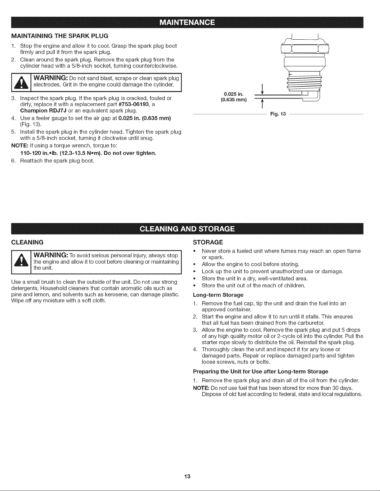
MAiNTAiNiNG THE SPARK PLUG
1. Stop the engine and allow it to cool. Grasp the spark plug boot
firmly and pull it from the spark plug.
2. Clean around the spark plug. Remove the spark plug from the
cylinder head with a 5/8-inch socket, turning counterclockwise.
I _ ! WARNING: Do not sand blast, scrape or clean spark plug 1
electrodes. Grit in the engine could damage the cylinder.
3. inspect the spark plug. if the spark plug is cracked, fouled or
dirty, replace it with a replacement part #753=06193, a
Champion RDJ7J or an equivalent spark plug.
4. Use a feeler gauge to set the air gap at 0.025 in. (0.635 ram}
(Fig. 13).
5. install the spark plug in the cylinder head. Tighten the spark plug
with a 5/8-inch socket, turning it clockwise until snug.
NOTE: if using a torque wrench, torque to:
110-120 in.olb. (12.3-13.5 Nora). Do not over tighten.
6. Reattach the spark plug boot.
0.025 in.
(0.6,35 ram) t
Fig. 13
CLEANING
WARNING, To avoid serious personal injury, always stop
the engine and allow it to cool before cleaning or maintaining
]
the unit.
Use a small brush to clean the outside of the unit. Do not use strong
detergents. Household cleaners that contain aromatic oils such as
pine and lemon, and solvents such as kerosene, can damage plastic.
Wipe off any moisture with a soft cloth.
STO RAG E
Never store a fueled unit where fumes may reach an open flame
or spark.
Allow the engine to cool before storing.
Lock up the unit to prevent unauthorized use or damage.
Store the unit in a dry, well-ventilated area.
Store the unit out of the reach of children.
Long-term Storage
1. Remove the fuel cap, tip the unit and drain the fuel into an
approved container.
2. Start the engine and allow it to run until it stalls. This ensures
that all fuel has been drained from the carburetor.
3. Allow the engine to cool. Remove the spark plug and put 5 drops
of any high quality motor oil or 2-cycle oil into the cylinder. Pull the
starter rope slowly to distribute the oil. Reinstall the spark plug.
4. Thoroughly clean the unit and inspect it for any loose or
damaged parts. Repair or replace damaged parts and tighten
loose screws, nuts or bolts.
Preparing the Unit for Use after Long-term Storage
1. Remove the spark plug and drain all of the oil from the cylinder.
NOTE: Do not use fuel that has been stored for more than 30 days.
Dispose of old fuel according to federal, state and local regulations.
13

CAUSE
Emptyfueltank
Thefuelisold(over30days)and/orimproperlymixed
ACTION
Fillfueltankwithproperlymixedfuel
Drainthefueltankandaddfresh,properlymixedfuel
Thefuelisold(over30days)and/orimproperlymixed
Dirtyairfilter
Fouledsparkplug
Drainthefueltankandaddfresh,properlymixedfuel
Cleanorreplacetheairfilter
Replaceorcleanthesparkplug
if further assistance is required, contact your authorized service dealer.
14
Congratulations on making a smart purchase. Your new Craftsman@ product is designed and manufactured for years of dependable
operation. But like all products, it may require repair from time to time. That's when having a Repair Protection Agreement can save you
money and aggravation.
Here's what the Repair Protection Agreement* includes:
[] Expert service by our 10,000 professional repair specialists
[] Unlimited service and no charge for parts and labor on all covered repairs
[] Product replacement up to $1500 if your covered product can't be fixed
[] Discount of 25% from regular price of service and related installed parts not covered by the agreement; also, 25% off regular price of
preventive maintenance check
[] Fast help by phone - we call it Rapid Resolution - phone support from a Sears representative. Think of us as a "talking owner's manual."
Once you purchase the Repair Protection Agreement, a simple phone call is all that it takes for you to schedule service. You can call anytime
day or night, or schedule a service appointment online.
The Repair Protection Agreement is a risk-free purchase. If you cancel for any reason during the product warranty period, we will provide a
full refund. Or, a prorated refund anytime after the product warranty period expires. Purchase your Repair Protection Agreement today!
Some limitations and exclusions apply. For prices and additional information in the U.S.A. call 1-800-827-6655.
*Coverage in Canada varies on some items. For full details call Sears Canada at 1-800-361-6665.
Sears Installation Service
For Sears professional installation of home appliances, garage door openers, water heaters, and other major home items, in the U.S.A. or
Canada call 1-800-4-MY-HOME.
15

16

17

18
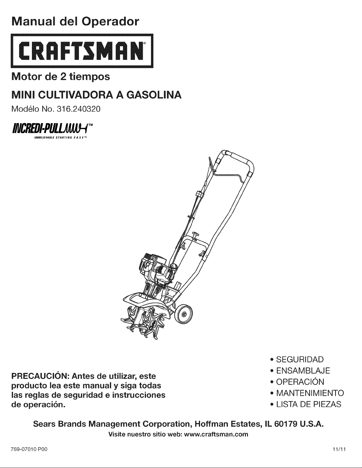
Manual del Operador
M
Motor de 2 tiempos
MINI CULTIVADORA A GASOLINA
Modelo No. 316.240320
INCREDI.PULL_TM
UNBELIEVABLE STARTING E A S E TM
PRECAUCION: Antes de utilizar, este
producto lea este manual y siga todas
Jas reglas de seguridad e instrucciones
de operaci6n.
• SEGURIDAD
• ENSAMBLAJE
• OPERACION
• MANTENIMIENTO
• LISTA DE PIEZAS
Sears Brands Management Corporation, Hoffman Estates, IL 60179 U.S.A.
Visite nuestro sitio web: www.craftsrnan.corn
769-07010 P00 11/11
TABLA DE CONTENIDO
Seguridad ........................................... 20
Garantia ............................................. 23
Conozca su unidad .................................... 24
Especificaciones ...................................... 24
Ensamblaje .......................................... 25
Aceite y combustible ................................... 26
Arranque y parada ..................................... 27
Operaci6n ........................................... 28
Mantenimiento ........................................ 29
Limpieza y almacenamiento ............................. 31
Localizaci6n y soluci6n de problemas ..................... 32
Convenio de protecci6n de reparaci6n ..................... 33
Lista de piezas ....................................... 38
NOmeros de servicio ......................... Contraportada
Toda la informaci6n, las ilustraciones y especificaciones que contiene
este manual se basan en la informaci6n m&s reciente del producto,
existente en el momento de la impresi6n. Nos reservamos el derecho
de hacer cambios en cualquier momento, sin previo aviso.
El prop6sito de los simbolos de seguridad es Ilamar la atenci6n
sobre posibles peligros. Los simbolos de seguridad y sus
explicaciones merecen toda su atenci6n y comprensi6n. Las
advertencias de seguridad no eliminan de pot si ningOn peligro.
Las instrucciones o advertencias que dan no sustituyen las
medidas adecuadas de prevenci6n de accidentes.
SiMBOLO SIGNIFICADO
PELIGRO: Indica un peligro EXTREMO.
El no obedecer una serial de seguridad de PELIGRO
TRAERA COMO CONSECUENCIA que usted u otras
personas puedan sufrir lesiones graves o la muerte.
ADVERTENOIA: Indica un peligro GRAVE.
El no obedecer una serial de ADVERTENCIA de seguridad
PUEDE conducir a que usted u otras personas sufran
graves lesiones.
PRECAUOION: Indica un peligro MODERADO.
El no obedecer una serial de PREOAUOION de seguridad
PUEDE conducir a dar_os a la propiedad o a que usted u
otras personas se lesionen.
NOTA: Indica informaci6n o instrucciones de vital importancia para
la operaci6n o el mantenimiento del equipo.
NOTA SOBRE EL PARACHISPAS
NOTA: Para usuarios de la Zona Forestal de EE. UU., y los
estados de California, Maine, Oreg6n y Washington. Todas las
zonas forestales de EE.UU., asi como los estados de California
(C6digos de Recursos PQblicos 4442 y 4443), Oreg6n y Washington
exigen, pot ley, que determinados motores de combusti6n interna
operados en matorrales boscosos y/o zonas cubiertas de hierba,
est6n equipados con un parachispas y se mantengan en buen estado
de funcionamiento, o que el motor sea construido, equipado y
mantenido con vista a la prevenci6n de incendios. Compruebe con
las autoridades de su estado o Iocalidad las reglamentaciones
relacionadas con estos requisitos. Si no cumple estos requisitos
podria estar sujeto a responsabilidad civil o multa. Esta unidad viene
equipada de f_brica con un parachispas. El reemplazo requiere la
pieza No. 753-06792 del conjunto del silenciador, instalada en un
Centro de Piezas y Servicio de Reparaciones de Sears.
PROPOSlCION 65 DEL ESTADO DE CALiFORNiA
ADVERTENClA: Los gases de escape, algunos de sus
componentes y determinados productos terminados
contienen o emiten productos quimicos de los que el estado
de California tiene conocimiento provocan cancer,
malformaciones cong6nitas u otros da_os al sistema
reproductor. L&vese las manos despu6s de manipularlos.
Lea el manual del operador y siga todas las advertencias e
instrucciones de seguridad. No hacerlo puede ocasionar
lesiones graves al operador y/o a las personas presentes.
20
o INSTRUCCIONES DE SEGURIDAD IMPORTANTES o
LEA TODAS LAS INSTRUCCIONES ANTES DE OPERAR
LA UNIDAD
_ DVERTENCIA: AI usar la unidad deben seguirse todas
las normas de seguridad. Lea estas instrucciones antes de
operar la unidad a fin de garantizar la seguridad del I
operador y de cualquier otra persona presente. Guarde I
estas instrucciones para poder usarlas mas adelante, j
• Lea detenidamente las instrucciones. Familiaricese con los
controles y el uso adecuado de la unidad.
No opere esta unidad siesta cansado, enfermo o bajo los
efectos del alcohol, drogas o medicamentos.
Los ni_os y adolescentes menores de 15 a_os no deben usar la
unidad. Los adolescentes pueden hacerlo bajo la supervisi6n de
un adulto.
Todos los accesorios de protecci6n y seguridad deben estar
instalados adecuadamente antes de comenzar a operar la unidad.
Inspeccione la unidad antes de utilizarla. Reemplace las piezas
da_adas. Verifique que no haya fugas de combustible. AsegOrese
de que todos los sujetadores est6n en su sitio y asegurados.
Cambie las piezas rajadas, melladas o da_adas de cualquier
forma. No opere la unidad si hay piezas flojas o da_adas.
Inspeccione cuidadosamente el area antes de encender la
unidad. Elimine todos los escombros y los objetos duros o
filosos tales como cristales, alambres, etc.
Tenga en cuenta el riesgo de lesiones a la cabeza, las manos y
los pies.
Limpie el area a recortar antes de cada uso. Retire las piedras,
vidrios rotos, clavos, alambres, cadenas y otros objetos que
podrian salir despedidos o enredarse en el accesorio de corte.
Aleje a los ni_os, personas presentes y animales dom6sticos del
area; mant6ngalos fuera de un radio de 50 pies (15 m) como
minimo. AOn asi es posible que se arriesguen a ser golpeados por
los objetos lanzados. Sugiera a los presentes usar protecci6n para
los ojos. Si alguien se le acerca, pare la unidad inmediatamente.
Apriete el control del regulador y compruebe que regresa
automaticamente a la posici6n de marcha en vacio. Haga todos
los ajustes o reparaciones antes de usar la unidad.
ADVERTENCIAS DE SEGURIDAD PARA UNIDADES DE
GASO LINA
ADVERTENCIA: La gasolina es sumamente inflamable I
y, de prenderse, sus vapores pueden hacer explosi6n. I
Tome las siguientes precauciones: j
Almacene el combustible solo en los recipientes dise_ados y
aprobados especificamente para estos materiales.
Pare siempre el motor y deje que se enfrie antes de Ilenar el
tanque. Nunca quite la tapa del tanque de combustible ni eche
combustible cuando el motor est6 caliente. Antes de Ilenar el
tanque, siempre afloje la tapa lentamente para disipar la presi6n
del mismo.
Mezcle o eche siempre el combustible en un area exterior bien
ventilada y limpia, donde no haya chispas ni llamas. NO fume.
No opere nunca la unidad si la tapa del combustible no esta
bien asegurada en su lugar.
Evite el peligro de incendio debido a combustible derramado.
Limpie de inmediato todo combustible derramado de la unidad
antes de encenderla. Antes de arrancar el motor, aleje la unidad
a una distancia de 30 pies (9.1 m) como minimo del lugar de
abasto de combustible. NO fume.
No arranque ni use nunca la unidad dentro de una habitaci6n o
edificio cerrados. Inhalar los gases de escape puede ser fatal.
Opere esta unidad solamente en un area exterior bien ventilada.
AL OPERAR LA UNIDAD
Lleve puestas gafas o lentes de seguridad que cumplan las
normas ANSI Z87.1-1989 y est6n marcados como tales. Use
siempre protecci6n para los oidos al operar esta unidad. Si la
operaci6n levanta polvo, Ileve puesta una mascara facial o
contra el polvo.
Use pantalones largos y gruesos, botas, guantes y camisa de
mangas largas. No use ropa holgada, alhajas, pantalones
cortos, sandalias ni ande descalzo. Asegure su cabello por
encima del nivel de los hombros.
Esta unidad tiene un embrague. Los dientes permanecen
estacionarios cuando el motor trabaja en vacio. De no hacerlo,
Ileve la unidad a Sears o a otro distribuidor de servicio calificado
para un ajuste.
Antes de arrancar la unidad, asegQrese de que los dientes no
est6n haciendo contacto con ningQn objeto.
Use la unidad Qnicamente a la luz del dia o con buena luz artificial.
Evite los arranques accidentales. P6ngase en la posici6n de
arranque siempre que tire de la cuerda. El operador y la unidad
deben estar en una posici6n estable durante el arranque.
Consulte la secci6n Arranque y Parada.
Use la herramienta correcta. Use esta herramienta solamente
con el prop6sito previsto.
Ponga extremo cuidado al dar marcha atras o retroceder la unidad.
No intente alcanzar demasiado lejos. Mantenga siempre una
posici6n y equilibrio adecuados. Tenga mucho cuidado cuando
est6 trabajando en pendientes pronunciadas o inclinadas.
Sostenga siempre la unidad con ambas manos al operarla.
Agarre firmemente ambos mangos o empu_aduras.
Mantenga las manos, la cara y los pies lejos de todas las partes
m6viles. No toque nitrate de detener los dientes cuando est6n
girando.
No toque el motor ni el silenciador. Estas partes se ponen
extremadamente calientes durante la operaci6n y aQn despu6s
de apagada la unidad.
No opere el motor a una velocidad mayor que la necesaria para
cultivar. No ponga a funcionar el motor a alta velocidad si no
esta cultivando.
Apague siempre el motor cuando el cultivo se demore o al caminar
de un lugar de cultivo a otro.
Si golpea o se enreda con un objeto extra,o, pare de inmediato
el motor y verifique si hay algQn da_o. No ponga a funcionar el
equipo sin reparar el da_o. No opere la unidad si hay piezas
flojas o da_adas.
Apague el motor y desconecte la bujia para darle mantenimiento
o hacer reparaciones.
Utilice solamente las piezas de repuesto y accesorios del
fabricante original que se listan en la secci6n Lista de piezas de
este manual. El uso de cualquier pieza o accesorio no
autorizado podria causar lesiones graves al usuario o da_os a la
unidad y anular la garantia.
Mantenga la unidad limpia de vegetaci6n y otros materiales que
puedan trabarse entre los dientes y el protector.
Para evitar el peligro de incendio, reemplace el silenciador y
parachispas defectuosos. Mantenga el motor y el silenciador sin
hierbas, hojas, grasa excesiva y sin acumulaci6n de carb6n.
21
OTRAS ADVERTENCIAS DE SEGURIDAD
• No guarde nunca la unidad con combustible en el tanque ni
dentro de una edificaci6n en la que los gases puedan ponerse
en contacto con una llama expuesta (luces piloto, etc.) o
chispas (interruptores, motores electricos, etc.).
Espere a que el motor se enfrie para guardar o transportar la
unidad. Cerci6rese de asegurar bien la unidad al transportarla.
Guarde la unidad en un lugar seco, bajo Ilave o en alto, a fin de
evitar su uso no autorizado o da_o. Mantengala fuera del
alcance de los ni_os.
Nunca moje ni rocie la unidad con agua ni con ningen otro
liquido. Mantenga las manijas secas, limpias y sin residuos.
Limpie la unidad luego de cada uso, lea las instrucciones de
Limpieza y Almacenamiento.
Limpie los dientes con un limpiador casero para eliminar la
acumulaci6n de resina. Engrase los dientes con aceite de
m_quina para evitar la corrosi6n.
Guarde estas instrucciones. Conseltelas con frecuencia y
utilicelas para instruir a otros usuarios. Si le presta esta unidad a
alguien, prestele tambien estas instrucciones.
GUARDE ESTAS INSTRUCCIONES
o SIMBOLOS DE SEGURIDAD E INTERNACIONALES o
Este manual del operador describe los simbolos y figuras de seguridad e internacionales que pueden aparecer en este producto. Lea el
manual del operador para obtener informaci6n completa acerca de la seguridad, ensamble, operaci6n y mantenimiento y reparaci6n.
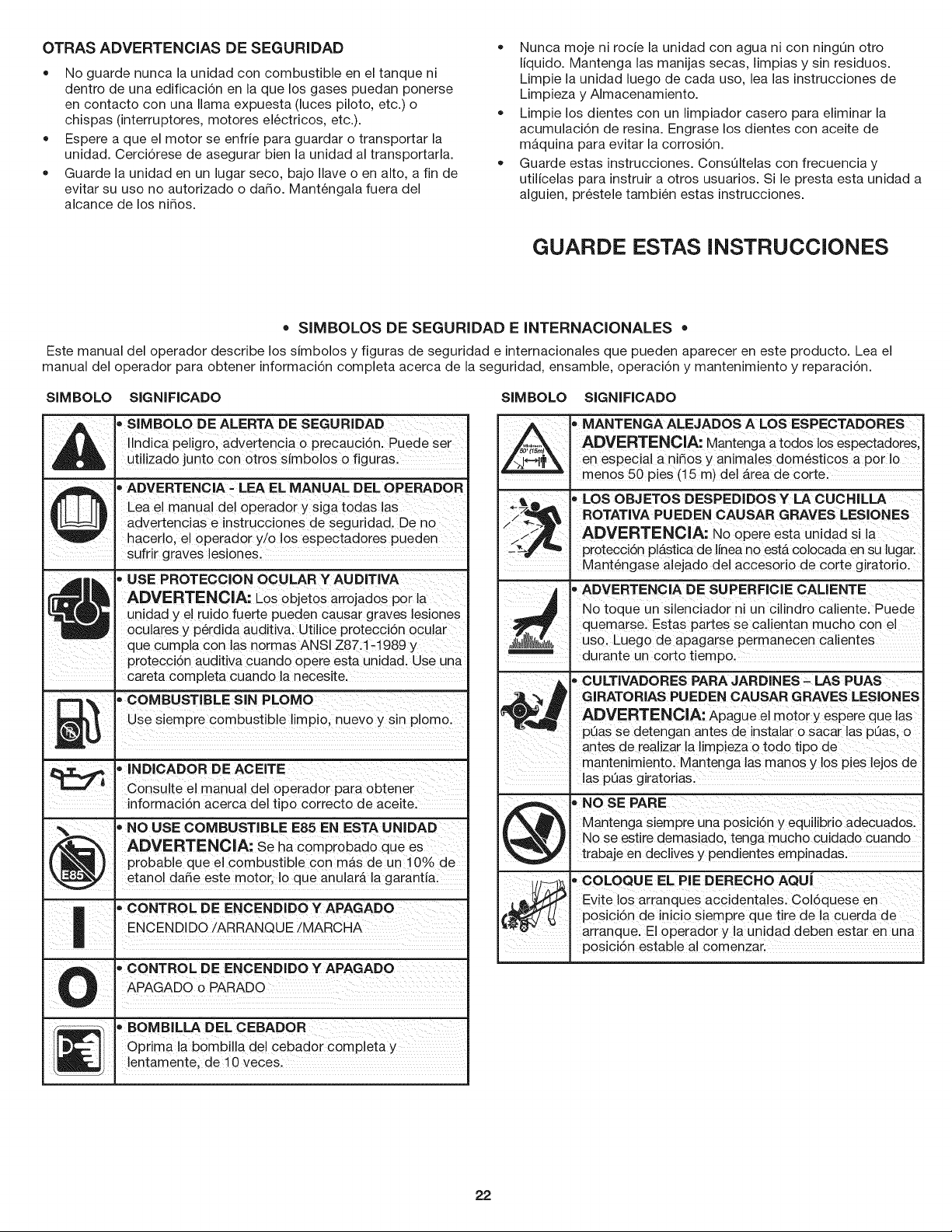
SIMBOLO SIGNIFICADO
_lb " SIMBOLO DE ALERTA DE SEGURIDAD
Ilndica peligro, advertencia o precauci6n. Puede ser
utilizado junto con otros simbolos o figuras.
• ADVERTENCIA - LEA EL MANUAL DEL OPERADOR
I Leaelmanualdeloperadorysigatodaslas
, advertencias e instrucciones de seguridad. De no
hacerlo, el operador y/o los espectadores pueden
sufrir graves lesiones.
4t _ • USE PROTECCION OCULAR Y AUDITIVA
ADVERTENCIA: Los objetos arrojados por la
h_! unidad y el ruJdo fuerte pueden causar graves lesionesoculares y p@dida auditiva. Utilice proteccien ocular
que cumpla con las normas ANSI Z87.1-1989 y
protecci6n auditiva cuando opere esta unidad. Use una
careta completa cuando la necesite.
_L_ PLOMm_ s p omo
O
COMBUSTIBLE SIN
Use siempre com ust nuevo y
b ibleli io in I .
,, INDICADOR DE ACEITE
J Consulte el manual del operador para obtener
Informaclon acerca de tlpo correcto de acelte.
%. ,, NO USE COMBUSTIBLE E85 EN ESTA UNIDAD
/_ ADVERTENCIA: Se ha comprobado que es
{ U ) probable que el combustible con mas de un 10% de
\\ etanol da5e este motor, Io que anular#, la garantJa.
n • CONTROL DE ENCENDIDO Y APAGADO
! I ENCEND DO/ARRANQUE/MARCHA
• CONTROL DE ENCENDIDO Y APAGADO
U APAGADO o PARADO
I
• BOMBiLLA DEL CEBADOR
| Optima la bombilla del cebador completa y
I_ . lentamente, de 10 veces.
SIMBOLO SIGNIFICADO
" MANTENGA ALEJADOS A LOS ESPECTADORE S
_,_ ADVERTENCIA: Mantenga a todos !os espectadores;
en especial a niSos y anima!es domesticos a pot Io
.... . menos 50 pies (15 m) de! Area de corte:
#_,_ , LOS OBJETOS DESPEDIDOSY LA CUCHILLA
Z_ _/_--_4_ ROTATIVA PUEDEN CAUSAR GRAVES LESIONES
ADVERTENCIA: N0 opere esta unidad Sila
/,iN
S_ protecci6n plastica de linea no esta coIocada en su lugar.
Mantengase a!ejado de! accesorio de corte giratorio,
, ADVERTENCIA DE SUPERFICIE CALIENTE
Notoqueuns,eno ad0rn!Unc, ndr0ca,ente:Puede
quemarse, Esta s partes se ca!ientan much0 con el
;_1_$1_11_, uso, Luego de apagarse permanecen calientes
durante un corto tiemPo.
, CULTIVADORES PARA JARDINES. LAS PUAS
GIRATORIAS PUEDEN CAUSAR GRAVES LESIONES
ADVERTENCIA: ApagUe el mot0r Y espere qUe ias
peas se detengan antes de insta!ar o sacar !as peas, o
antes de realizar !a limpieza o todo tip0 de
mantenimient0; Mantenga !as manos y !os pies lejos de
!as Peas giratorias.
@ _ NOSE PARE
Mantenga siempre una posicien y equi!ibrio adecuados.
NO se estire demasiado, tenga mucho cuidado cuando
trabaje en declives y pendientes empinadas.
__, COLOQUE EL PIE DERECHO AQUj
Evite los arianques accidenta!es: Coldquese en
posicidn de inJcio siernpre que tire dela cuerda de
arranquel El 0perad0r y !a unJdad deben estar en una
posici6n estab!e al comenzar,
22
GARANTIA TOTAL POR DOS ANOS CRAFTSMAN
Este producto se garantiza POR DOS ANOS a partir de la fecha de compra, contra cualquier defecto de materiales o mano de obra. Un
producto defectuoso se reparar& sin costo alguno o se remplazar& si no es posible repararlo.
Para conocer los detailes de la cobertura de garantia para la reparaci6n o reemplazo gratuitos, visite el sitio web: www.craftsman.com
Esta garantia cubre SOLAMENTE defectos de materiales o mano de obra. La cobertura de garantia NO incluye:
• Articulos consumibles que se desgasten debido al uso normal dentro del periodo de la garantia, tales como cuchillas, dientes o correas.
• Los dados al producto a consecuencia de intentos de modificaci6n o reparaci6n del usuario u ocasionados por accesorios del producto.
• Las reparaciones necesarias por un accidente o por no operar o mantener el producto de acuerdo con todas las instruccione$ suministradas.
• El mantenimiento preventivo ni las reparacione$ necesarias debido a una mezcla incorrecta de combustible o a al uso de un combustible
viejo o contaminado.
Esta garantia se anula si el producto en algL_nmomento se utiliza para prestar servicios comerciale$ o se alquila a otra persona.
Esta garantia le confiere a usted derechos legale$ especificos y usted puede tener, adem&s, otros derechos que difieren de un estado a otro.
Sears Brands Management Corporation, Hoffman Estates, iL 60179
PARA PREGUNTAS SOBRE SEGURIDAD, OPERAClON Y MANTENIMIENTO MIENTRAS DURE LA GARANTIA O PARA
ORDENAR PIEZAS Y PROGRAMAR EL SERVlClO DE REPARAClON, LLAME AL I-800-4-MY=HOME®.
23
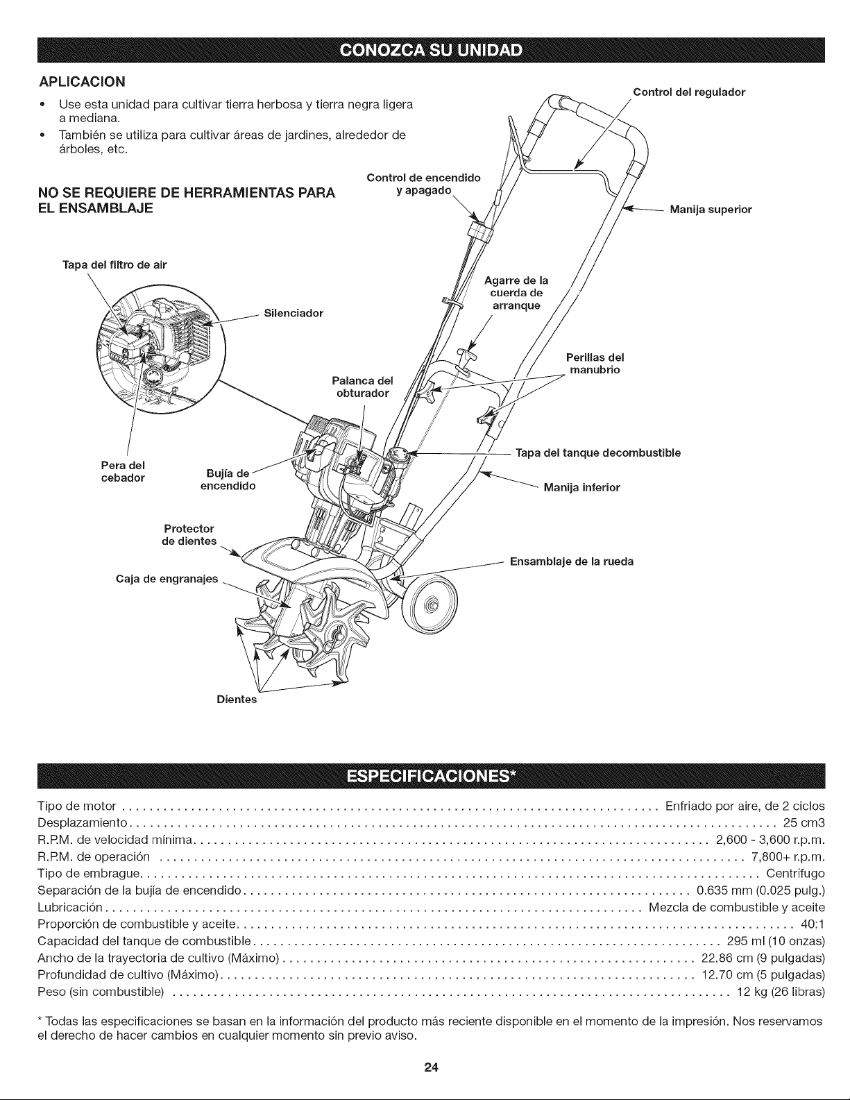
APLICACION
• Use esta unidad para cultivar tierra herbosa y tierra negra ligera
a mediana.
Tambi6n se utiliza para cultivar &reas de jardines, alrededor de
&rboles, etc.
Control deJ regulador
NO SE REQUIERE DE HERRAMIENTAS PARA
EL ENSAMBLAJE
Control de encendido
y apagado
Manija superior
Tapa deJ filtro de air
SiJenciador
Agarre de Ja
cuerda de
arranque
Palanca del
obturador
Perillas deJ
manubrio
Pera del
cebador
Buj
encendido
Tapa deJ tanque decombustible
Manija inferior
Protector
de dientes
Caja de engranajes
Ensamblaje de la rueda
Dientes
Tipo de motor .............................................................................. Enfriado por aire, de 2 ciclos
Desplazamiento .............................................................................................. 25 cm3
R.RM. de velocidad minima ........................................................................... 2,600 - 3,600 r.p.m.
R.RM. de operaci6n ..................................................................................... 7,800+ r.p.m.
Tipo de embrague .......................................................................................... Centrifugo
Separaci6n de la bujia de encendido ................................................................. 0.635 mm (0.025 pulg.)
Lubricaci6n .............................................................................. Mezcla de combustible y aceite
Proporci6n de combustible y aceite ................................................................................. 40:1
Capacidad del tanque de combustible .................................................................... 295 ml (10 onzas)
Ancho de la trayectoria de cultivo (Maximo) ............................................................ 22.86 cm (9 pulgadas)
Profundidad de cultivo (M_.ximo) ..................................................................... 12.70 cm (5 pulgadas)
Peso (sin combustible) ................................................................................. 12 kg (26 libras)
* Todas las especificaciones se basan en la informaci6n del producto m&s reciente disponible en el momento de la impresi6n. Nos reservamos
el derecho de hacer cambios en cualquier momento sin previo aviso.
24
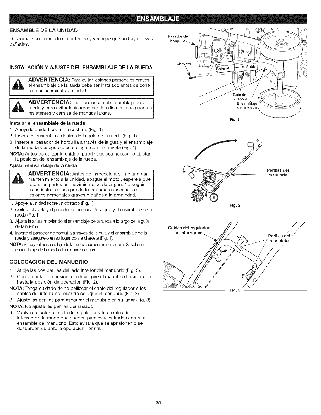
ENSAMBLE DE LA UNIDAD
Desembale con cuidado el contenido y verifique que no haya piezas
da_adas.
Pasador de
horquilla-...
INSTALACION Y AJUSTE DEL ENSAMBLAJE DE LA RUEDA
ADVERTENCIA: Para evitar lesiones personales graves, J
el ensamblaje de la rueda debe ser nsta ado antes de poner
en funcionamiento la unidad.
I _ I ADVERTENCIA: Cuando instale el ensamblaje gde/ate s
rueda y para evitar lesionarse con los dientes, use
resistentes y camisa de mangas largas.
Instalar el ensamblaje de la rueda
1. Apoye la unidad sobre un costado (Fig. 1).
2. Inserte el ensamblaje dentro de la guia de la rueda (Fig. 1)
3. Inserte el pasador de horquilla a trav6s de la guia y el ensamblaje
de la rueda y asegOrelo en su lugar con la chaveta (Fig. 1).
NOTA: Antes de utilizar la unidad, puede que sea necesario ajustar
la posici6n del ensamblaje de la rueda.
Ajustar el ensamblaje de la rueda
L_ DVERTENCIA: Antes de inspeccionar, limpiar o dar
mantenimiento a la unidad, apague el motor, espere a que
todas las partes en movimiento se detengan. No seguir
estas instrucciones puede traer como consecuencia
lesiones personales graves o dados a la propiedad.
1. Apoye la unidad sobre un costado (Fig.1).
2. Quite la chaveta y el pasador de horquilla de laguia y el ensamblaje de la
rueda (Fig. 1).
3. Ajuste la altura moviendo el ensamblaje de la rueda a Io largo de la guia
de la misma.
4. Inserte el pasador de horquilla a trav6s de la guia y el ensamblaje de la
rueda y asegQreloen su lugar con la chaveta (Fig. 1).
NOTA: Si baja el ensamblaje de la rueda aumentar_ su altura. Si sube el
ensamblaje de larueda disminuir_ su altura.
COLOCAClON DEL MANUBRIO
1. Afloje las dos perillas del lado interior del manubrio (Fig. 3).
2. Con la unidad en posici6n vertical, gire el manubrio hacia arriba
hasta la posici6n de operaci6n (Fig. 2).
NOTA: Tenga cuidado de no pellizcar el cable del regulador o los
cables del interruptor cuando coloque el manubrio (Fig. 3).
3. Ajuste las perillas para asegurar el manubrio en su lugar (Fig. 3).
NOTA: No ajuste las perillas demasiado.
4. Vuelva a ajustar el cable del regulador y los cables del
interrupter de modo que queden parejos y estirados contra el
ensamble del manubrio. Esto evitar& que se aprisionen o se
desbarben durante la operaci6n normal.
Chaveta
\
Guia de
la rueda
Ensamblaje
de la rueda
Fig. 1
Fig. 2
Perillas del
manubrio
Cables del regulador
e interruptor
Perillas del_
manubrio
Fig. 3
25
INSTRUCCIONES PARA MEZCLAR EL ACEITE Y EL
COMBUSTIBLE
El uso de un combustible viejo y/o mal mezclado es la causa mas
comQn de problemas de funcionamiento. Utilice solamente
gasolina fresca, limpia y sin plomo. Siga atentamente las
instrucciones para mezclar adecuadamente el aceite/combustible.
Definici6n de combustibles mezclados
Los combustibles actuales son con frecuencia una mezcla de
gasolina e hidrocarburos oxigenados como el etanol, metanol o
MTBE (6ter). El combustible mezclado con alcohol absorbe agua.
Un 1% de agua es suficiente para separar la mezcla de aceite y
alcohol o formar acidos al estar guardado. Utilice SiEMPRE
combustible fresco (con menos de 30 dias).
NOTA: Deseche el aceite viejo, de conformidad con las regulaciones
federales, estatales y locales.
Uso de combustibles mezclados
Si utiliza un combustible mezclado:
• Utilice siempre la mezcla fresca de combustible indicada en su
manual del operador
Use el aditivo STA-BIL® o un equivalente
Agite siempre la mezcla de combustible antes de abastecer la
unidad
Vacie el tanque y eche a andar el motor en seco antes de
guardar la unidad
ADVERTENCIA: NO USE COMBUSTIBLE E85EN
ESTA UNIDAD. Se ha comprobado que es probable que el
combustible con m_s de 10% de etanol daSe este motor, Io
que anular& la garantia.
Uso de aditivos para combustible
La botella de aceite para motor de 2 tiempos que viene con esta
unidad contiene un aditivo que ayudar& a inhibit la corrosi6n y
minimizar_ los dep6sitos de goma. Utilice siempre la marca de aceite
para motor de 2 tiempos que viene con esta unidad. Si no es posible,
utilice un buen aceite para motores de 2 tiempos enfriados por aire y
m6zclelo con un aditivo como el estabilizador de gasolina STA-BIL o
un equivalente. Eche 0.8 onzas (23 ml) de aditivo por gal6n de
combustible seg0n las instrucciones del recipiente. No eche NUNCA
los aditivos directamente en el tanque de combustible de la unidad.
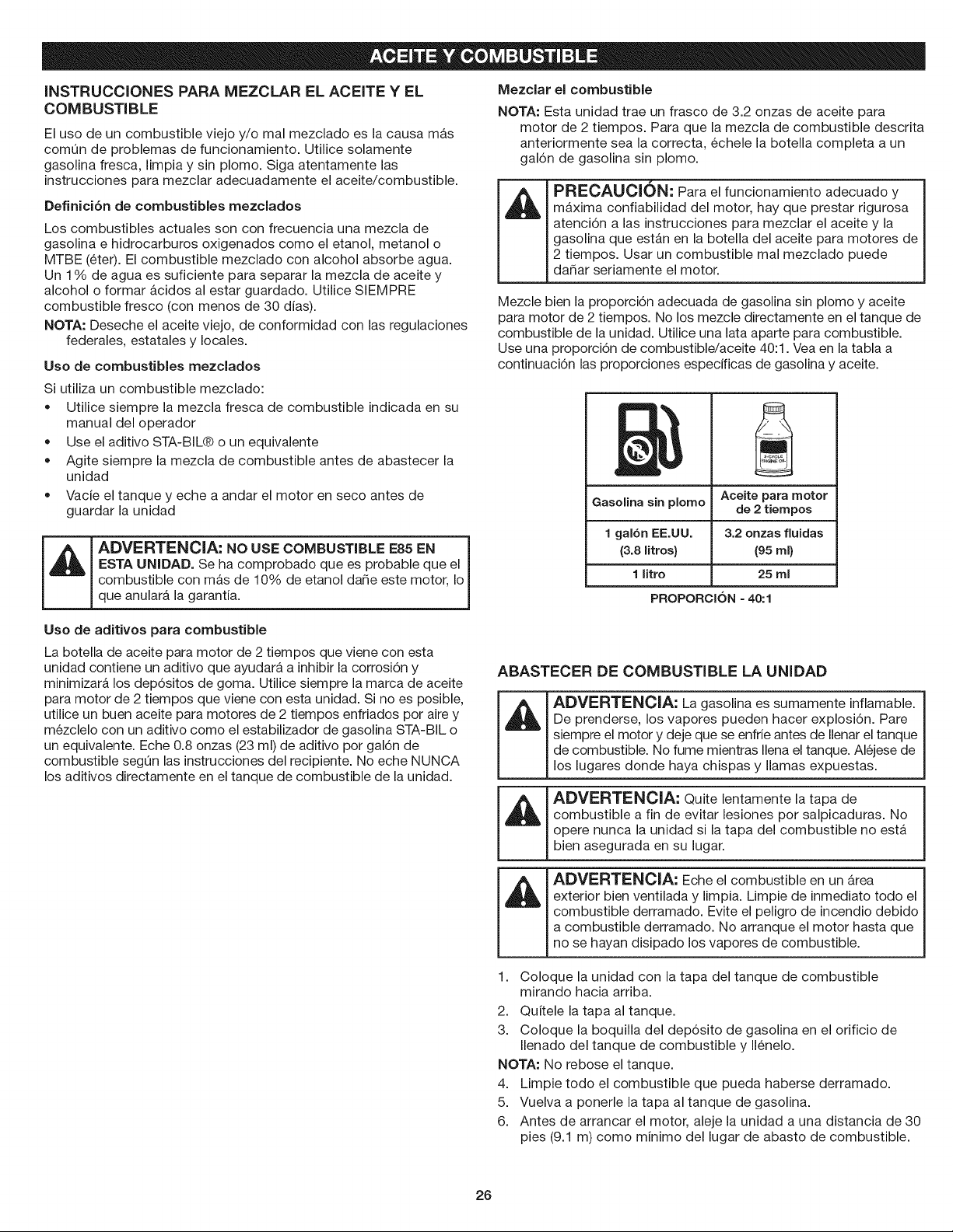
Mezclar eJ combustibJe
NOTA: Esta unidad trae un frasco de 3.2 onzas de aceite para
motor de 2 tiempos. Para que la mezcla de combustible descrita
anteriormente sea la correcta, 6chele la botella completa a un
gal6n de gasolina sin plomo.
_mA/HAm_
FHir.L;AUL;IUII" Para el funcionamiento adecuado y
m_xima confiabilidad del motor, hay que prestar rigurosa
atenci6n alas instrucciones para mezclar el aceite y la
gasolina que est_n en la botella del aceite para motores de
2 tiempos. Usar un combustible real mezclado puede
da5ar seriamente el motor.
Mezcle bien la proporci6n adecuada de gasolina sin plomo y aceite
para motor de 2 tiempos. No los mezcle directamente en el tanque de
combustible de la unidad. Utilice una lata aparte para combustible.
Use una proporci6n de combustible/aceite 40:1. Vea en la tabla a
continuaci6n las proporciones especificas de gasolina y aceite.
GasoJina sin pJomo
1 gal6n EE.UU.
(3.8 litros}
1 litro
PROPORCION = 40:1
Aceite para motor
de 2 tiempos
3.2 onzas fluidas
(95 ml)
25 mJ
ABASTECER DE COMBUSTIBLE LA UNIDAD
I'1
I'1
1.
2.
3.
ADVERTENCIA: La gasolina es sumamente inflamable.
De prenderse, los vapores pueden hacer explosi6n. Pare
siempre el motor y deje que se enfrie antes de Ilenar el tanque
de combustible. No fume mientras Ilena el tanque. AI6jese de
los lugares donde haya chispas y llamas expuestas.
ADVERTENClA: Quite lentamente la tapa de
combustible a fin de evitar lesiones por salpicaduras. No
opere nunca la unidad si la tapa del combustible no est&
bien asegurada en su lugar.
ADVERTENClA: Eche el combustible en un &rea
exterior bien ventilada y limpia. Limpie de inmediato todo el
combustible derramado. Evite el peligro de incendio debido
a combustible derramado. No arranque el motor hasta que
no se hayan disipado los vapores de combustible.
Coloque la unidad con la tapa del tanque de combustible
mirando hacia arriba.
Quitele la tapa al tanque.
Coloque la boquilla del dep6sito de gasolina en el orificio de
Ilenado del tanque de combustible y 116nelo.
NOTA: No rebose el tanque.
4. Limpie todo el combustible que pueda haberse derramado.
5. Vuelva a ponerle la tapa al tanque de gasolina.
6. Antes de arrancar el motor, aleje la unidad a una distancia de 30
pies (9.1 m) como minimo del lugar de abasto de combustible.
26
ADVERTENClA: Opere esta unidad solamente en un
&tea exterior bien ventilada. El mon6xido de carbono de
los gases de escape puede ser letal en un &tea confinada.
ADVERTENOIA: Evite arrancar la unidad por
accidente. A fin de evitar lesiones graves, el operador y la
unidad deben estar en una posici6n estable al tirar de la
cuerda de arranque (Fig. 7).
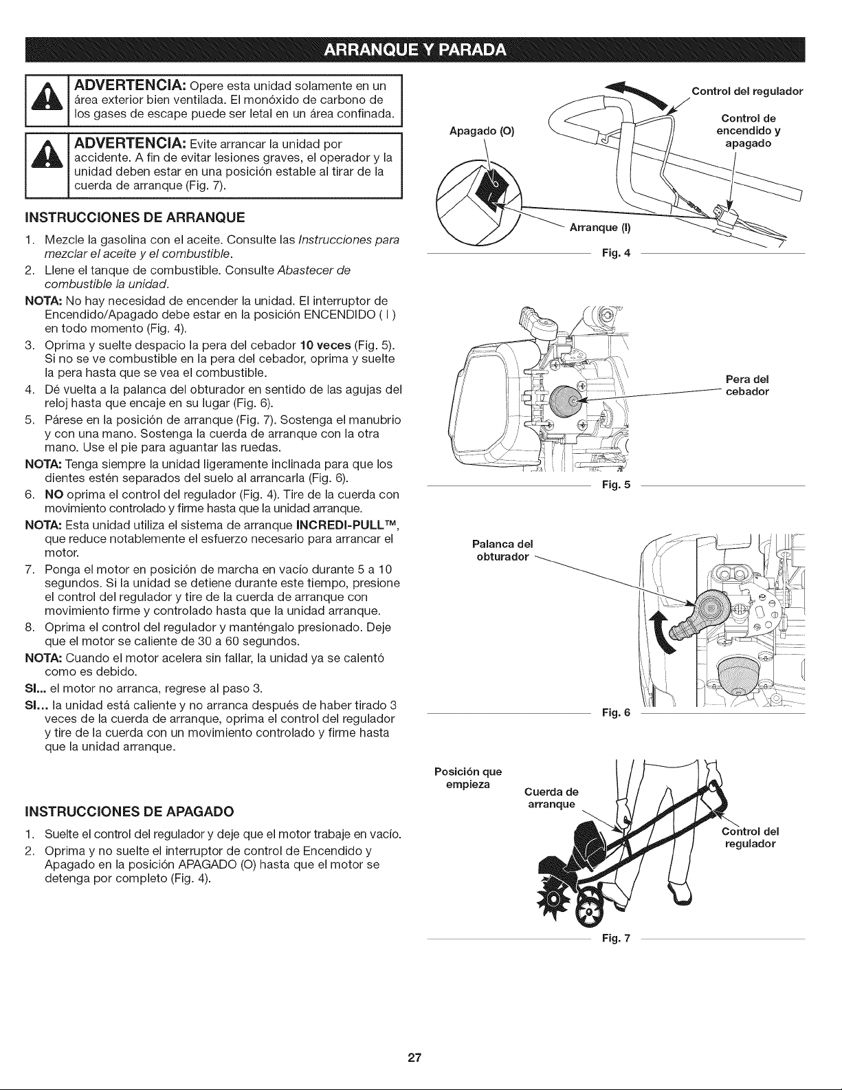
INSTRUCClONES DE ARRANQUE
Apagado(O)
Control del regulador
Control de
encendido y
apagado
1. Mezcle la gasolina con el aceite. Consulte las Instrucciones para
mezclar el aceite y el combustible.
2. Llene el tanque de combustible. Consulte Abastecer de
combustible la unidad.
NOTA: No hay necesidad de encender la unidad. El interruptor de
Encendido/Apagado debe estar en la posici6n ENCENDIDO (I)
en todo momento (Fig. 4).
3. ©prima y suelte despacio la pera del cebador 10 veces (Fig. 5).
Si no se ve combustible en la pera del cebador, oprima y suelte
la pera hasta que se vea el combustible.
4. D6 vuelta a la palanca del obturador en sentido de las agujas del
reloj hasta que encaje en su lugar (Fig. 6).
5. P&rese en la posici6n de arranque (Fig. 7). Sostenga el manubrio
y con una mano. Sostenga la cuerda de arranque con la otra
mano. Use el pie para aguantar las ruedas.
NOTA: Tenga siempre la unidad ligeramente inclinada para que los
dientes est6n separados del suelo al arrancarla (Fig. 6).
6. NO optima el control del regulador (Fig. 4). Tire de la cuerda con
movimiento controlado y firme hasta que la unidad arranque.
NOTA: Esta unidad utiliza el sistema de arranque INCREDI-PULL TM,
que reduce notablemente el esfuerzo necesario para arrancar el
motor.
7. Ponga el motor en posici6n de marcha en vacio durante 5 a 10
segundos. Si la unidad se detiene durante este tiempo, presione
el control del regulador y tire de la cuerda de arranque con
movimiento firme y controlado hasta que la unidad arranque.
8. Oprima el control del regulador y mant6ngalo presionado. Deje
que el motor se caliente de 30 a 60 segundos.
NOTA: Cuando el motor acelera sin fallar, la unidad ya se calent6
como es debido.
SL. el motor no arranca, regrese al paso 3.
SI... la unidad est,. caliente y no arranca despu6s de haber tirado 3
veces de la cuerda de arranque, oprima el control del regulador
y tire de la cuerda con un movimiento controlado y firme hasta
que la unidad arranque.
Arranque (I)
Fig. 4
Fig. 5
Palanca del
obturador
Fig. 6
Pera del
cebador
INSTRUCCIONES DE APAGADO
1.
2.
Suelte el control del regulador y deje que el motor trabaje en vacio.
©prima y no suelte el interruptor de control de Encendido y
Apagado en la posici6n APAGADO (O) hasta que el motor se
detenga por completo (Fig. 4).
Posici6n que
empieza
Cuerda de
arranque
Control del
regulador
Fig. 7
27
ADVERTENCIA: Vista en forma adecuada para reducir
el riesgo de lesiones cuando opere esta unidad. No use
ropa holgada ni alhajas. Use protecci6n ocular y auditiva.
Use pantalones largos y gruesos, botas y guantes. No use
pantalones cortos, sandalias ni trabaje descalzo.
CONSEJOS PARA LA OPERACION
1. Transporte el cultivador hacia el _.reade trabajo antes de arrancar el
motor. Consulte Mover la unidad.
_ DVERTENClA: Para evitar graves lesiones j
personales, nunca levante ni transporte la unidad con el
motor en marcha.
2. Arranque la unidad siguiendo las Instrucciones de arranque.
3. Sin apoyar los dientes en el suelo, apriete el control del
regulador para aumentar la velocidad del motor.
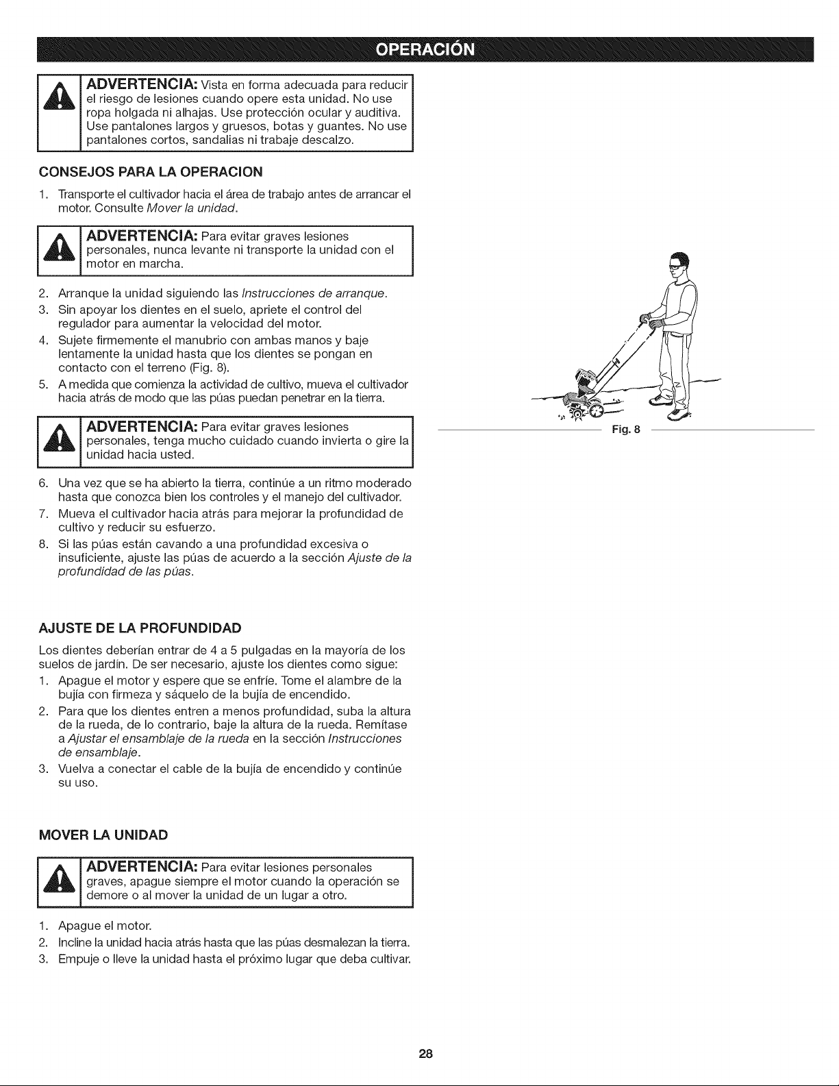
4. Sujete firmemente el manubrio con ambas manos y baje
lentamente la unidad hasta que los dientes se pongan en
contacto con el terreno (Fig. 8).
5. A medida que comienza la actividad de cultivo, mueva el cultivador
hacia atr&s de modo que las pQas puedan penetrar en la tierra.
6.
7.
8.
ADVERTENClA: Para evitar graves lesiones i
personales, tenga mucho cuidado cuando invierta o gire la
J
unidad hacia usted.
Una vez que se ha abierto la tierra, continOe a un ritmo moderado
hasta que conozca bien los controles y el manejo del cultivador.
Mueva el cultivador hacia atras para mejorar la profundidad de
cultivo y reducir su esfuerzo.
Si las pOas est_.n cavando a una profundidad excesiva o
insuficiente, ajuste las pOas de acuerdo a la secci6n Ajuste de la
profundidad de las pOas.
Fig. 8
AJUSTE DE LA PROFUNDIDAD
Los dientes deberian entrar de 4 a 5 pulgadas en la mayoria de los
suelos de jardin. De ser necesario, ajuste los dientes como sigue:
1. Apague el motor y espere que se enfrie. Tome el alambre de la
bujia con firmeza y s&quelo de la bujia de encendido.
2. Para que los dientes entren a menos profundidad, suba la altura
de la rueda, de Io contrario, baje la altura de la rueda. Remitase
a Ajustar el ensamblaje de la rueda en la secci6n Instrucciones
de ensamblaje.
3. Vuelva a conectar el cable de la bujia de encendido y continOe
SU USO.
MOVER LA UNIDAD
_ ADVERTENCIA: Para evitar lesiones personales j
graves, apague siempre el motor cuando la operaci6n se
demote o al mover la unidad de un lugar a otto.
1. Apague el motor.
2. Incline la unidad hacia atr&s hasta que las pOas desmalezan latierra.
3. Empuje o Ileve la unidad hasta el pr6ximo lugar que deba cultivar.
28
ADVERTENClA: Para evitar lesiones graves, no haga
nunca ningQn mantenimiento ni reparaci6n con la unidad
funcionando. Siempre deje que la unidad se enfrie antes de
darle mantenimiento o repararla. Desconecte el cable de la
bujia para evitar que la unidad arranque por accidente.
PLAN DE MANTENIMIENTO
Lleve a cabo los procedimientos necesarios de mantenimiento con
la frecuencia indicada en la tabla. Estos procedimientos deber&n
tambi6n format parte de cualquier ajuste de temporada.
NOTA: Es posible que algunos procedimientos de mantenimiento
requieran herramientas o habilidades especiales. Si no est&
seguro de poder Ilevar a cabo estos procedimientos, Ileve la
unidad a Sears u otro distribuidor de servicio calificado. Para
m_s informaci6n, Ilame al 1-800=4-MY-HOME.
NOTA: Es conveniente que el mantenimiento, reemplazo o
reparaci6n de los dispositivos y sistemas de control de emisiones
se Ileven a cabo en Sears u otro distribuidor de servicio
calificado. Para m&s informaci6n, Ilame al 1-800=4-MY-HOME.
NOTA: Para ver la lista completa de t6rminos y la cobertura de los
dispositivos de control de emisiones como parachispas,
silenciador, carburador, etc., lea la declaraci6n de California/
EPA que viene junto con la unidad.
FRECUENCIA MANTENIMIENTO NECESARIO
Cada 10 horas Limpiar y volver a engrasar el filtro de aire.
Consulte Mantenimiento del filtro de aire.
Cada 25 horas Comprobar el estado y abertura de la bujia.
Consulte Mantenimiento de la bujfa.
REMOCION Y REPOSICION DE LAS PUAS
_ ADVERTENClA: Para evitar graves lesiones personales, j
use siempre guantes gruesos cuando maneje las pQas.
NOTA: Todas las instrucciones de instalaci6n se explican desde la
posici6n de funcionamiento.
Las 4 pQas deben cambiarse al mismo tiempo debido a que se
desgastar&n en forma pareja con el uso normal. Trabaje en un lado
por vez.
1. Apague el motor y espere que se enfrie. Tome el alambre de la
bujia con firmeza y s&quelo de la bujia de encendido.
2. Coloque la parte posterior de la cultivadora sobre una superficie
plana con las manijas tocando el suelo de manera que la
cultivadora quede en posici6n horizontal.
NOTA: Para poder sacar los dientes m_.s fb.cilmente, es posible que
sea necesario lavar los dientes y el eje para quitar la suciedad.
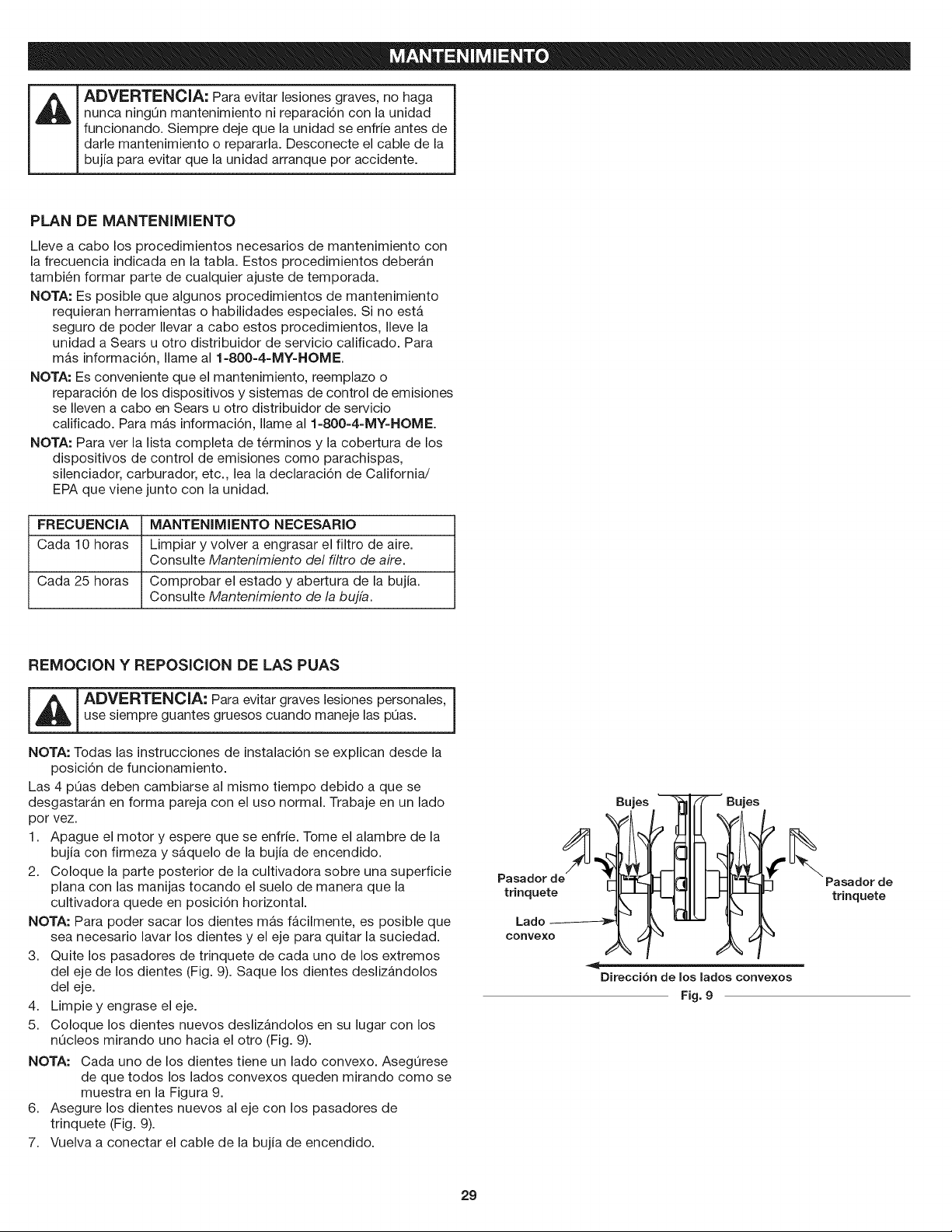
3. Quite los pasadores de trinquete de cada uno de los extremos
del eje de los dientes (Fig. 9). Saque los dientes deslizandolos
del eje.
4. Limpie y engrase el eje.
5. Coloque los dientes nuevos deslizandolos en su lugar con los
nOcleos mirando uno hacia el otro (Fig. 9).
NOTA: Cada uno de los dientes tiene un lado convexo. AsegOrese
de que todos los lados convexos queden mirando como se
muestra en la Figura 9.
6. Asegure los dientes nuevos al eje con los pasadores de
trinquete (Fig. 9).
7. Vuelva a conectar el cable de la bujia de encendido.
Pasador
trinquete
Lado
convexo
Bujes
' Bujes
Pasador de
trinquete
Direcci6n de los lados convexos
Fig. 9
29
MANTENIMIENTO DEL FILTRO DE AIRE
Limpiar el filtro de aire
No mantener debidamente su filtro de aire puede resultar en
funcionamiento inadecuado o puede causar dar_o permanente a su
motor.
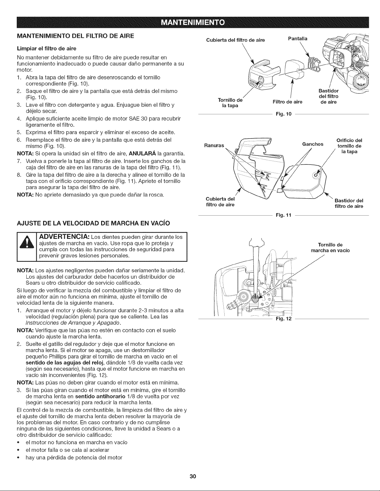
1. Abra la tapa del filtro de aire desenroscando el tornillo
correspondiente (Fig. 10).
2. Saque el filtro de aire y la pantalla que est,. detr_.s del mismo
(Fig. 10).
3. Lave el filtro con detergente y agua. Enjuague bien el filtro y
d6jelo secar.
4. Aplique suficiente aceite limpio de motor SAE 30 para recubrir
ligeramente el filtro.
5. Exprima el filtro para esparcir y eliminar el exceso de aceite.
6. Reemplace el filtro de aire y la pantalla que est,. detr_.s del
mismo (Fig. 10).
NOTA: Si opera la unidad sin el filtro de aire, ANULARA la garantia.
7. Vuelva a ponerle la tapa al filtro de aire. Inserte los ganchos de la
caja del filtro de aire en las ranuras de la tapa del filtro (Fig. 11).
8. Gire la tapa del filtro de aire a la derecha y alinee el tornillo de la
tapa con el orificio correspondiente (Fig. 11). Apriete el tornillo
para asegurar la tapa del filtro de aire.
NOTA: No apriete demasiado ya que puede dar_ar la rosca.
Cubierta del filtro de aire
\
TorniUo de
la tapa
RanlLll'as
Cubierta del
filtro de aire
Pantalla
BastJdor
I del filtro
Filtro de aire de aire
Fig. 10
Ganchos
Orificio del
torniUo de
la tapa
Bastidordel
filtro de aire
Fig. 11
AJUSTE DE LA VELOCIDAD DE MARCHA EN VACJO
ADVERTENCIA: Los dientes pueden girar durante los
ajustes de marcha en vacio. Use ropa que Io proteja y
cumpla con todas las instrucciones de seguridad para
prevenir graves lesiones personales.
NOTA: Los ajustes negligentes pueden dar_ar seriamente la unidad.
Los ajustes del carburador debe hacerlos un distribuidor de
Sears u otro distribuidor de servicio calificado.
Si luego de verificar la mezcla del combustible y limpiar el filtro de
aire el motor aQn no funciona en minima, ajuste el tornillo de
velocidad lenta de la siguiente manera.
1. Arranque el motor y d6jelo funcionar durante 2-3 minutos a alta
velocidad (regulaci6n plena) para que se caliente. Lea las
Instrucciones de Arranque y Apagado.
NOTA: Verifique que las pQas no est6n en contacto con el suelo
cuando ajuste la marcha lenta.
2. Suelte el gatillo del regulador y deje que el motor funcione en
marcha lenta. Si el motor se apaga, use un destornillador
pequer_o Phillips para girar el tornillo de marcha en vacio en el
sentido de las agujas del reloj, d_ndole 1/8 de vuelta cada vez
(segQn sea necesario), hasta que el motor funcione en marcha en
vacio sin inconvenientes (Fig. 12).
NOTA: Las pQas no deben girar cuando el motor est& en minima.
3. Si las pQas giran cuando el motor est& en minima, gire el tornillo
de marcha lenta en sentido antihorario 1/8 de vuelta por vez
(segQn sea necesario) para reducir la marcha lenta.
El control de la mezcla de combustible, la limpieza del filtro de aire y
el ajuste del tornillo de marcha lenta deben resolver la mayoria de
los problemas del motor. En caso contrario y de no cumplirse
ninguna de las siguientes condiciones, Ileve la unidad a Sears o a
otro distribuidor de servicio calificado:
• el motor no funciona en marcha en vacio
el motor falla o se cala al acelerar
Tornillode
marcha en vacio
Fig. 12
hay una p6rdida de potencia del motor
3O
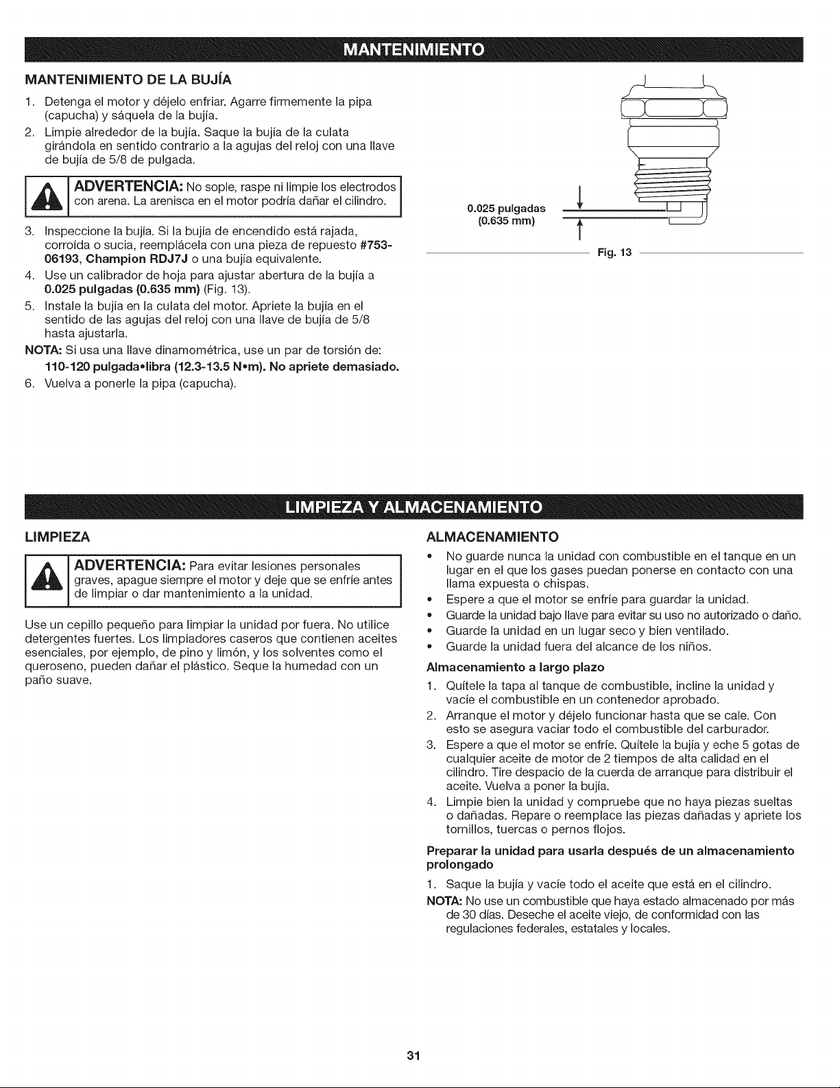
MANTENIMIENTO DE LA BUJJA
1. Detenga el motor y d6jelo enfriar. Agarre firmemente la pipa
(capucha) y s&quela de la bujia.
2. Limpie alrededor de la bujia. Saque la bujia de la culata
gir&ndola en sentido contrario a la agujas del reloj con una Ilave
de bujia de 5/8 de pulgada.
_ DVERTENCIA: No sople, raspe ni limpie los electrodos
con arena. La aren sca en e motor podr a da5ar e c ndro.
3. Inspeccione la bujia. Si la bujia de encendido est_ rajada,
corroida o sucia, reempl&cela con una pieza de repuesto #753-
06193, Champion RDJ7J o una bujia equivalente.
4. Use un calibrador de hoja para ajustar abertura de la bujia a
0.025 pulgadas (0.635 ram} (Fig. 13).
5. Instale la bujia en la culata del motor. Apriete la bujia en el
sentido de las agujas del reloj con una Ilave de bujia de 5/8
hasta ajustarla.
NOTA: Si usa una Ilave dinamom6trica, use un par de torsi6n de:
110=120 pulgadaolibra (12.3=13.5 Nore}. No apriete demasiado.
6. Vuelva a ponerle la pipa (capucha).
0.025 pulgadas
(0.635 mm)
t
Fig. 13
LIMPIEZA
ADVERTENClA: Para evitar lesiones personales j
graves, apague siempre el motor y deje que se enfrie antes
de limpiar o dar mantenimiento a la unidad.
Use un cepillo peque_o para limpiar la unidad por fuera. No utilice
detergentes fuertes. Los limpiadores caseros que contienen aceites
esenciales, por ejemplo, de pino y lim6n, y los solventes como el
queroseno, pueden da_ar el pl&stico. Sequela humedad con un
patio suave.
ALMACENAMIENTO
No guarde nunca la unidad con combustible en el tanque en un
lugar en el que los gases puedan ponerse en contacto con una
llama expuesta o chispas.
Espere a que el motor se enfrie para guardar la unidad.
Guarde la unidad bajo Ilave para evitar su uso no autorizado o da_o.
Guarde la unidad en un lugar seco y bien ventilado.
Guarde la unidad fuera del alcance de los ni_os.
Almacenamiento a largo plazo
1. Quitele la tapa al tanque de combustible, incline la unidad y
vacie el combustible en un contenedor aprobado.
2. Arranque el motor y d6jelo funcionar hasta que se cale. Con
esto se asegura vaciar todo el combustible del carburador.
3. Espere a que el motor se enfrie. Quitele la bujia y eche 5 gotas de
cualquier aceite de motor de 2 tiempos de alta calidad en el
cilindro. Tire despacio de la cuerda de arranque para distribuir el
aceite. Vuelva a poner la bujia.
4. Limpie bien la unidad y compruebe que no haya piezas sueltas
o dadadas. Repare o reemplace las piezas dadadas y apriete los
tornillos, tuercas o pernos flojos.
Preparar la unidad para usarla despu_s de un almacenamiento
prolongado
1. Saque la bujia y vacie todo el aceite que est_ en el cilindro.
NOTA: No use un combustible que haya estado almacenado por mAs
de 30 dias. Deseche el aceite viejo, de conformidad con las
regulaciones federales, estatales y locales.
31
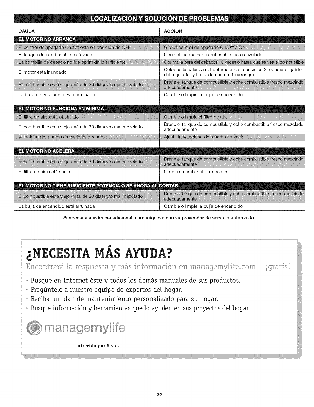
CAUSA ACCION
El tanque de combustible est_ vacio
El motor est& inundado
La bujia de encendido est& arruinada
!!!! !!!!i!!!!!!!!! ! !!!!!!!!
El combustible est& viejo (m&s de 30 dias) y/o mal mezclado
Llene el tanque con combustible bien mezclado
_iiiiii_ iiiii iiiii iiiiiiiiiiiiiiiiiiiiiiiiiiiiiiiiii_iiiiiiiiiiiiiiiiiiiiiiiiiiiiiiiiiiiiiiiiiiiiiiiiiiiiiiiiiiHHH_iiiiii_!_!_!_!_!_!_!_!_!_!_!_!_!_!_!_!_!_!_!_!_!_!_!_!_!_!_!_!_!_!_i iiii_iiiiiiiiiiii_iiiiiii_iiiiii_ H _i iiiiiiiiiiiiii_iiiiiiiiiiiiii__iiiiiiiiiiiiiiiiiiiiiiiiiiiiiiiiiiiiiiiiiiiii_ iiiiiiiiiiiiiiiiiiiiiiiii_ iiii_ii!!!!!!!!!!!iiiiiiiiiiiiiiiiiiiiiiiiiiiiiiiiiiiiiiiiiiiiiiiiiiiiiiiiiii!!!!!i
Coloque la palanca del obturador en la posici6n 3, oprima el gatillo
del regulador y tire de la cuerda de arranque.
Cambie o limpie la bujia de encendido
Drene el tanque de combustible y eche combustible fresco mezclado
adecuadamente
El filtro de aire est& sucio
Limpie o cambie el filtro de aire
La bujia de encendido esta arruinada Cambie o limpie la bujia de encendido
Si necesita asistencia adicional, comuniquese con su proveedor de servicio autorizado,
32
Felicitaciones por haber hecho una compra inteligente. Su nuevo producto Craftsman@ fue dise_ado y fabricado con vistas a una operaci6n
confiable por a_os. Pero como todos los productos, es posible que sea necesario repararlo alguna vez. Ahi es cuando tener un Convenio de
Protecci6n de Reparaci6n puede ahorrarle dinero y problemas.
Esto es Io que incluye el ConvenJo de Protecci6n de Reparaci6n*:
[] Servicio de experto por nuestros 10,000 profesionales, especialistas en reparaciones
[] Servicio ilimitado y sin costo aJguno en piezas y mano de obra para todas las reparaciones cubiertas
[] Reemplazo del producto por otro que cueste hasta $1500 si el producto cubierto no tiene reparaci6n
[] Descuento del 25% del precio normal por el servicio y las piezas instaladas que no cubra el convenio; asi como tambi6n el 25% de
descuento por el mantenimiento preventivo
[] Ayuda r_pida pot teJ6fono - la Ilamamos Soluci6n Rapida - asistencia t6cnica por tel6fono de un representante de Sears.
Consid6renos un "manual de usuario que habla".
Una vez que adquiera el Convenio de Protecci6n de Reparaci6n, todo Io que necesita es hacer una simple Ilamada para programar el
servicio. Puede Ilamar a cualquier hora del dia o de la noche o programar el servicio por Internet.
El Convenio de Protecci6n de Reparaci6n es una compra libre de riesgo. Si usted Io cancela por cualquier motivo mientras dure la garantia
del producto, le haremos un reembolso completo. Si Io hace en cualquier momento despu6s de vencida la garantia, le haremos un
reembolso prorrateado, iAdquiera hoy mismo su Convenio de Protecci6n de Reparaci6n!
Se aplJcan algunas limitaciones y exclusiones. Rata precios e informaci6n adicional en Estados Unidos, Ilame al 1=800=827=6655.
*La cobertura en Canad_ varia en algunos articulos. Para todos los detalles, Ilame a Sears de Canad_ al 1=800=361=6665.
Servicio de Instalaci6n Sears
Para la instalacidn de electrodom6sticos, abrepuertas de garajes, calentadores de agua, y otros productos para el hogar por profesionales
de Sears, en Estados Unidos o Canad&, Ilame al 1=800=4=MY=HOME.
33

34

35

36

37
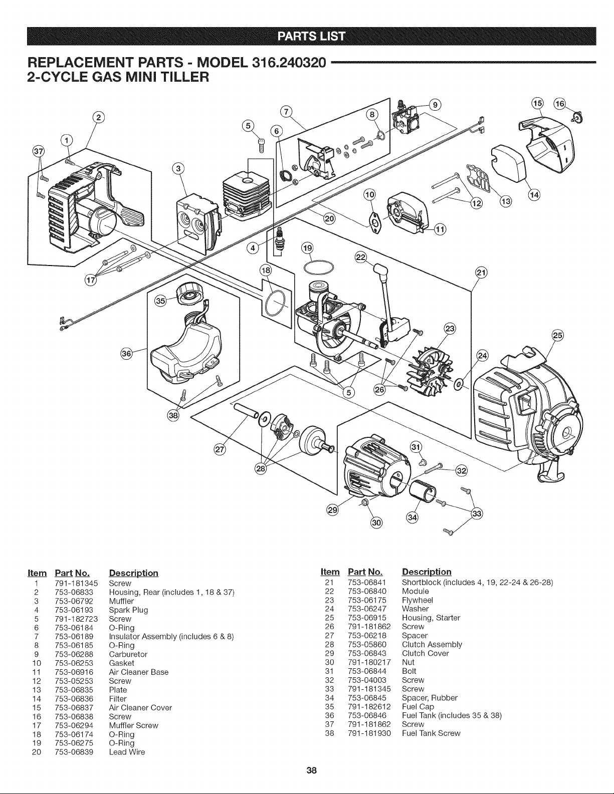
REPLACEMENT PARTS - MODEL 316.240320
2-CYCLE GAS MiNi TILLER
item Part No. Description item Part No. Description
1 791-181345 Screw 21 753-06841 Shortblock (includes 4, 19, 22-24 & 26-28)
2 753-06833 Housing, Rear (includes 1,18 & 37) 22 753-06840 Module
3 753-06792 Muffler 23 753-06175 Flywheel
4 753-06193 Spark Plug 24 753-06247 Washer
5 791-182723 Screw 25 753-06915 Housing, Starter
6 753-06184 O-Ring 26 791-181862 Screw
7 753-06189 Insulator Assembly (includes 6 & 8) 27 753-06218 Spacer
8 753-06185 O-Ring 28 753-05860 Clutch Assembly
9 753-06288 Carburetor 29 753-06843 Clutch Cover
10 753-06253 Gasket 30 791-180217 Nut
11 753-06916 Air Cleaner Base 31 753-06844 Bolt
12 753-05253 Screw 32 753-04003 Screw
13 753-06835 Plate 33 791-181345 Screw
14 753-06836 Filter 34 753-06845 Spacer, Rubber
15 753-06837 Air Cleaner Cover 35 791-182612 Fuel Cap
16 753-06838 Screw 36 753-06846 Fuel Tank (includes 35 & 38)
17 753-06294 Muffler Screw 37 791-181862 Screw
18 753-06174 O-Ring 38 791-181930 Fuel Tank Screw
19 753-06275 O-Ring
20 753-06839 Lead Wire
38
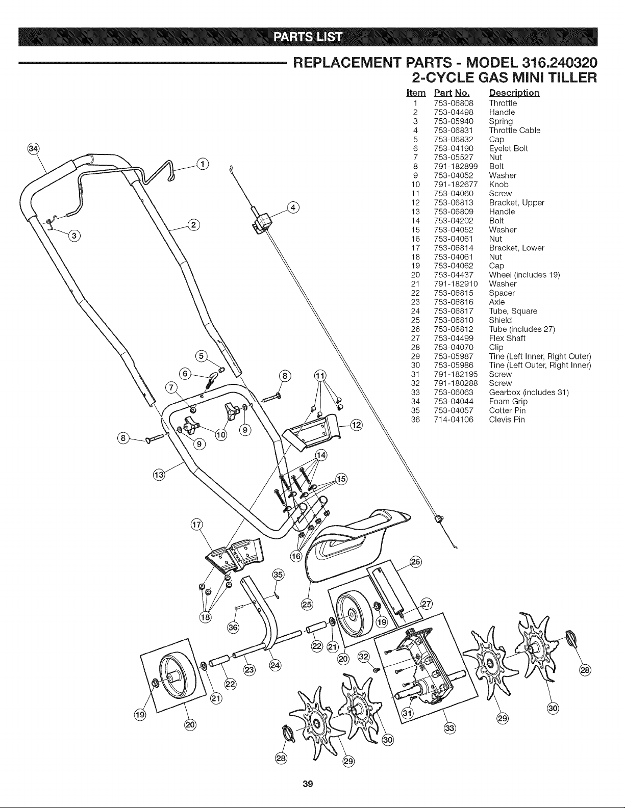
REPLACEMENT PARTS = MODEL 316.240320
2-CYCLE GAS MINI TILLER
item Part No. Description
1 753-06808 Throttle
2 753-04498 Handle
3 753-05940 Spring
4 753-06831 Throttle Cable
5 753-06832 Cap
6 753-04190 Eyelet Bolt
7 753-05527 Nut
8 791-182899 Bolt
9 753-04052 Washer
10 791-182677 Knob
11 753-04060 Screw
12 753-06813 Bracket, Upper
13 753-06809 Handle
14 753-04202 Bolt
15 753-04052 Washer
16 753-04061 Nut
17 753-06814 Bracket, Lower
18 753-04061 Nut
19 753-04062 Cap
20 753-04437 Wheel (includes 19)
21 791-182910 Washer
22 753-06815 Spacer
23 753-06816 Axle
24 753-06817 Tube, Square
25 753-06810 Shield
26 753-06812 Tube (includes 27)
27 753-04499 Flex Shaft
28 753-04070 Clip
29 753-05987 Tine (Left Inner, Right Outer)
30 753-05986 Tine (Left Outer, Right Inner)
31 791-182195 Screw
32 791-180288 Screw
33 753-06063 Gearbox (includes 31)
34 753-04044 Foam Grip
35 753-04057 Cotter Pin
36 714-04106 Clevis Pin
39
@

Your Home
For troubleshooting, product manuals and expert advice:
managernylife
www.managernylife.corn
For repair- in your home - of all major brand appliances,
lawn and garden equipment, or heating and cooling systems,
no matter who made it, no matter who sold it!
For the replacement parts, accessories and
owner's manuals that you need to do-it-yourself.
For Sears professional installation of home appliances
and items like garage door openers and water heaters.
1-800-4-MY-HOME ® (_-8oo-409-4003)
Call anytime, day or night (U.S.A. and Canada)
www.sears.com www.sears.ca
Our Home
For repair of carry-in items like vacuums, lawn equipment,
and electronics, call anytime for the location of your nearest
Sears Parts & Repair Service Center
1-800-488-1222 (U.S.A.) 1-800-469-4663 (Canada)
www.sears.corn www.sears.ca
To purchase a protection agreement on a product serviced by Sears:
1-800-827-8655 (U.S.A.) 1-800-361-6665 (Canada)
Para pedir servicio de reparaci6n Au Canada pour service en fran(_ais:
a domicilio, y para ordenar piezas:
1-888-SU-HOGAR ®
(1-888-784-6427)
www.sears.com
s ars
1-800-LE-FOYER Mc
(1-800-533-6937
www.sears.ca
® Registered Trademark / TMTrademark of KCD IP, LLC in the United States, or Sears Brands, LLC in other countries
® Marca Registrada / TMMarca de FAbrica de KCD IP, LLC en Estados Unidos, o Sears Brands, LLC in otros paises
MCMarque de commerce / MDMarque d6pos6e de Sears Brands, LLC