EN
W415-1662 / 05.17.16
FR
PG
27
INSTALLER: LEAVE THIS MANUAL WITH THE APPLIANCE.
CONSUMER: RETAIN THIS MANUAL FOR FUTURE REFERENCE.
NEVER LEAVE CHILDREN OR OTHER AT RISK INDIVIDUALS ALONE WITH THE APPLIANCE.
INSTALLATION AND
OPERATING INSTRUCTIONS
1.16F
Wolf Steel Ltd., 24 Napoleon Rd., Barrie, ON, L4M 0G8 Canada /
103 Miller Drive, Crittenden, Kentucky, USA, 41030
Phone (705)721-1212 • Fax (705)720-9081 • www.napoleonfi replaces.com •[email protected]
SAFETY INFORMATION
!
WARNING
If the information in these instructions
are not followed exactly, a fi re may result
causing property damage, personal injury
or loss of life.
- Do not store or use gasoline or other fl ammable
vapors and liquids in the vicinity of this or any
other appliance.
$10.00
CERTIFIED UNDER CANADIAN AND AMERICAN NATIONAL STANDARDS: CSA C22.2 No-46 / UL 2021
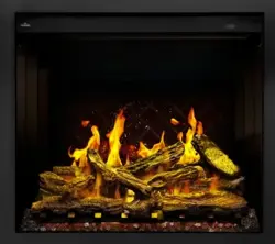
NEFB24HG, NEFB27HG &
NEFB29HG
ELECTRIC FIREPLACE

EN
W415-1662 / 05.17.16
2
NOTE: Changes, other than editorial, are denoted by a vertical line in the margin.
TABLE OF CONTENTS
1.0 INTRODUCTION 3
1.1 DIMENSIONS 4
1.2 LISTING APPROVALS 5
1.3 GENERAL INSTRUCTIONS 5
1.4 RATING PLATE INFORMATION 6
1.5 LABEL LOCATION 6
2.0 LOCATING APPLIANCE 7
2.1 UNPACKING AND TESTING APPLIANCE 7
2.2 GROUNDING APPLIANCE 7
3.0 INSTALLATION 8
3.1 MINIMUM CLEARANCE TO COMBUSTIBLES 8
3.2 MINIMUM MANTEL CLEARANCES 8
3.3 FRAMING 9
3.3.1 HARD WIRING INSTALLATION 10
3.3.2 APPLIANCE INSTALLATION 11
4.0 OPERATING INSTRUCTIONS 12
4.1 OPERATING CONTROL PANEL 12
4.2 OPERATING BY REMOTE CONTROL 13
5.0 FINISHING 14
5.1 GLASS DOOR REMOVAL AND INSTALLATION 14
5.2 PLACING GLASS MEDIA 14
5.3 GLASS MEDIA EMBER BED ASSEMBLY REMOVAL 15
6.0 WIRING DIAGRAM 16
7.0 REPLACEMENT PARTS 17
7.1 NEFB24HG OVERVIEW 18
7.2 NEFB27HG OVERVIEW 19
7.3 NEFB29HG OVERVIEW 20
8.0 TROUBLESHOOTING 21
9.0 WARRANTY 23
10.0 SERVICE HISTORY 24
11.0 NOTES 25
Batteries must be disposed of according to the local laws and regulations. Some batteries may be
recycled, and may be accepted for disposal at your local recycling center. Check with your municipality
for recycling instructions.
Les piles doivent être mises au rebut conformément aux lois et à la réglementation locales. Certaines
piles peuvent être recyclées et acceptées dans votre centre de recyclage local. Renseignez-vous auprès
de votre municipalité au sujet des directives de recyclage.
EN
W415-1662 / 05.17.16
3
1.0 INTRODUCTION
!
WARNING
3.7C
C
• THIS APPLIANCE IS HOT WHEN OPERATED AND CAN CAUSE SEVERE BURNS IF
CONTACTED.
• Do not operate appliance before reading and understanding operating instructions. Failure to operate
appliance according to operating instructions could cause fi re or injury.
• Risk of burns. Power to the appliance should be turned off and the appliance allowed to cool before
servicing. To disconnect power to the appliance, turn controls to off, then remove plug from outlet.
• Do not install damaged, incomplete or substitute components.
• Do not burn wood or other materials in this appliance.
• Young children should be carefully supervised when they are in the same room as the appliance.
Toddlers, young children and others may be susceptible to accidental contact burns. A physical barrier
is recommended if there are at risk individuals in the house. To restrict access to an appliance or stove,
install an adjustable safety gate to keep toddlers, young children and other at risk individuals out of the
room and away from hot surfaces.
• Clothing or other fl ammable material should not be placed on or near the appliance.
• Due to high temperatures, the appliance should be located out of traffi c and away from furniture and
draperies.
• Ensure you have incorporated adequate safety measure to protect infants/toddlers from touching hot
surfaces.
• Even after the appliance is out, the glass and/or screen will remain hot for an extended period of time.
• Check with your local hearth specialty dealer for safety screens and hearth guards to protect children
from hot surfaces. These screens and guards must be fastened to the fl oor.
• Any safety screen or guard removed for servicing must be replaced prior to operating the appliance.
• It is imperative that the control compartments, circulating blower and its passageway in the appliance
and are kept clean. The appliance should be inspected before use and at least annually by a qualifi ed
service person. More frequent cleaning may be required due to excessive lint from carpeting, bedding
material, etc. The appliance area must be kept clear and free from combustible materials, gasoline and
other fl ammable vapors and liquids.
• Under no circumstances should this appliance be modifi ed.
• Do not use this appliance if any part has been under water. Immediately call a qualifi ed service technician
to inspect the appliance and to replace any part of the control system which has been under water.
• Do not operate the appliance with the glass door removed, cracked or broken. Replacement of the
glass should be done by a licensed or qualifi ed service person.
• Do not strike or slam shut the appliance glass door.
• Keep the packaging material out of reach of children and dispose of the material in a safe manner. As
with all plastic bags, these are not toys and should be kept away from children and infants.
• Servicing should be done only while the appliance is disconnected from the power supply circuit.
• Always unplug appliance when not in use.
• Do not operate this appliance with a damaged cord or plug after the appliance malfunctions, has been
dropped or damaged in any manner. Return appliance to authorized service facility for examination,
electrical or mechanical adjustment, or repair.
• Do not use outdoors.
• Never locate appliance where it may fall into a bathtub or other water container.
• Do not run cord under carpeting. Do not cover cord with throw rugs, runners, or the like. Arrange cord
away from traffi c area and where it will not be tripped over.
• Connect to properly grounded outlets only.
• Do not insert or allow foreign objects to enter any ventilation or exhaust opening as this may cause an
electric shock or fi re, or damage the appliance.
• To prevent a possible fi re, do not block air intakes or exhaust in any manner. Do not use on soft
surfaces, like a carpet, where openings may become blocked.
• Always plug appliances directly into a wall outlet/receptacle. Never use an extension cord or
relocatable power tap (outlet/power strip).
• Ensure clearances to combustibles are maintained when building a mantel or shelves above the
appliance. Elevated temperatures on the wall or in the air above the appliance can cause melting,
discolouration or damage to decorations, a T.V. or other electronic components.
EN
W415-1662 / 05.17.16
4
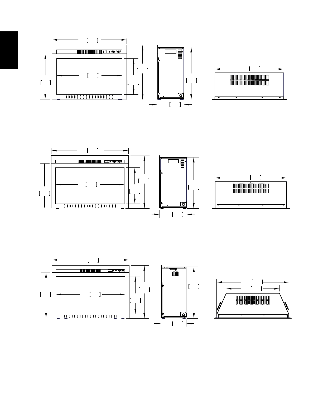
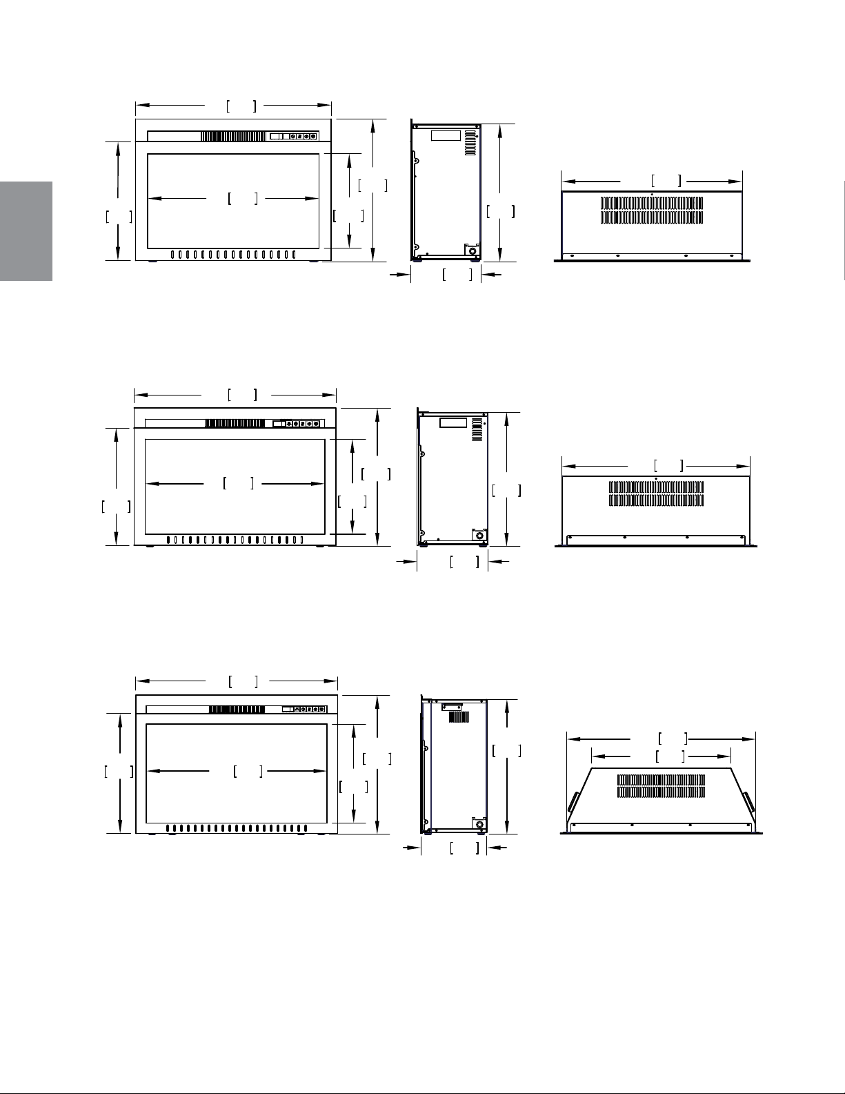
1.1 DIMENSIONS
CEFB24H ILLUSTRATED
CEFB27H ILLUSTRATED
24"
610mm
18 5/8"
473mm
15 3/4"
399mm
12 3/4"
323mm
18"
457mm
9 1/2"
241mm
25 1/8"
639mm
21"
533mm
17 5/8"
448mm
14 5/8"
371mm
11 5/8"
294mm
8 5/8"
219mm
17"
432mm
22 1/8"
563mm
20 1/8"
511mm
26"
660mm
17 1/4"
437mm
14 1/4"
361mm
9 1/2"
241mm
19 1/2"
495mm
27 1/4"
691mm
20 1/8"
510mm
CEFB29H ILLUSTRATED
24"
610mm
27"
686mm
29"
737mm
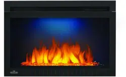
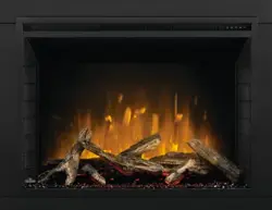
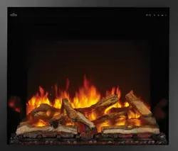
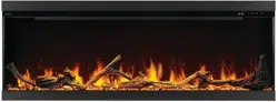
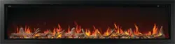
NEFB24HG ILLUSTRATED
NEFB27HG ILLUSTRATED
NEFB29HG ILLUSTRATED
EN
W415-1662 / 05.17.16
5
4.8B
A.
Prior to plugging your appliance into an electrical outlet, verify that the house circuit breakers for the
outlet are on.
B.
The appliance may emit a slight, harmless odour when fi rst used. This odour is normal and it is caused
by the initial heating of internal appliance elements and will not occur again.
C.
If your appliance does not emit heat, consult the operation section of this manual for further
information.
D.
Use with a CSA- or UL-certifi ed surge protector.
E.
Do not route the power cord directly underneath the appliance.
This electric appliance meets the construction and safety standards of H.U.D. for application in manufactured
homes when installed according to these instructions.
!
WARNING
READ THESE INSTRUCTIONS COMPLETELY BEFORE BEGINNING INSTALLATION. FAILURE TO
FOLLOW THEM COULD CAUSE AN APPLIANCE MALFUNCTION RESULTING IN SERIOUS INJURY
AND/OR PROPERTY DAMAGE.
ALL ELECTRIC APPLIANCES HAVE HOT AND ARCING OR SPARKING PARTS INSIDE. DO NOT USE
IT IN AREAS WHERE GASOLINE, PAINT OR FLAMMABLE LIQUIDS ARE PRESENT.
THIS ELECTRIC APPLIANCE IS TESTED AND LISTED FOR USE ONLY WITH THE OPTIONAL
ACCESSORIES LISTED IN THESE INSTRUCTIONS. USE OF OPTIONAL ACCESSORIES NOT
SPECIFICALLY TESTED FOR THIS ELECTRIC APPLIANCE COULD VOID THE WARRANTY AND/OR
RESULT IN A SAFETY HAZARD.
DO NOT OPEN. RISK OF ELECTRIC SHOCK. NO USER-SERVICEABLE PARTS INSIDE.
DO NOT USE DAMAGED ELECTRICAL CORDS.
SERVICING SHOULD BE DONE ONLY WHILE THE APPLIANCE IS DISCONNECTED FROM THE
POWER SUPPLY CIRCUIT.
TO PREVENT ELECTRIC SHOCK MATCH THE WIDE BLADE OF PLUG TO WIDE SLOT OF
RECEPTACLE AND FULLY INSERT.
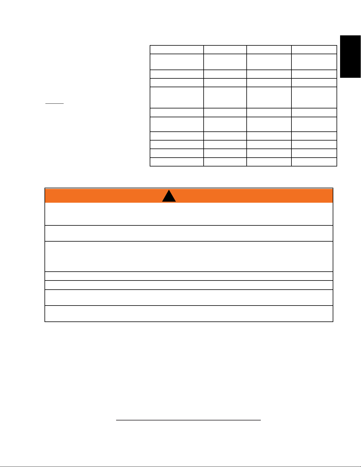
1.2 LISTING APPROVALS
This appliance has been tested in
accordance with the CSA Standards
for fixed and location-dedicated
electric room appliances in the United
States and Canada. If you need
assistance during installation, please
contact your local dealer.
NOTE: This appliance must be
electrically wired and grounded
in accordance with local codes
or, in the absence of local codes,
with National Electric Code ANSI/
NFPA 70-latest edition in the United
States or the Canadian Electric
Code, CSA C22.1 in Canada.
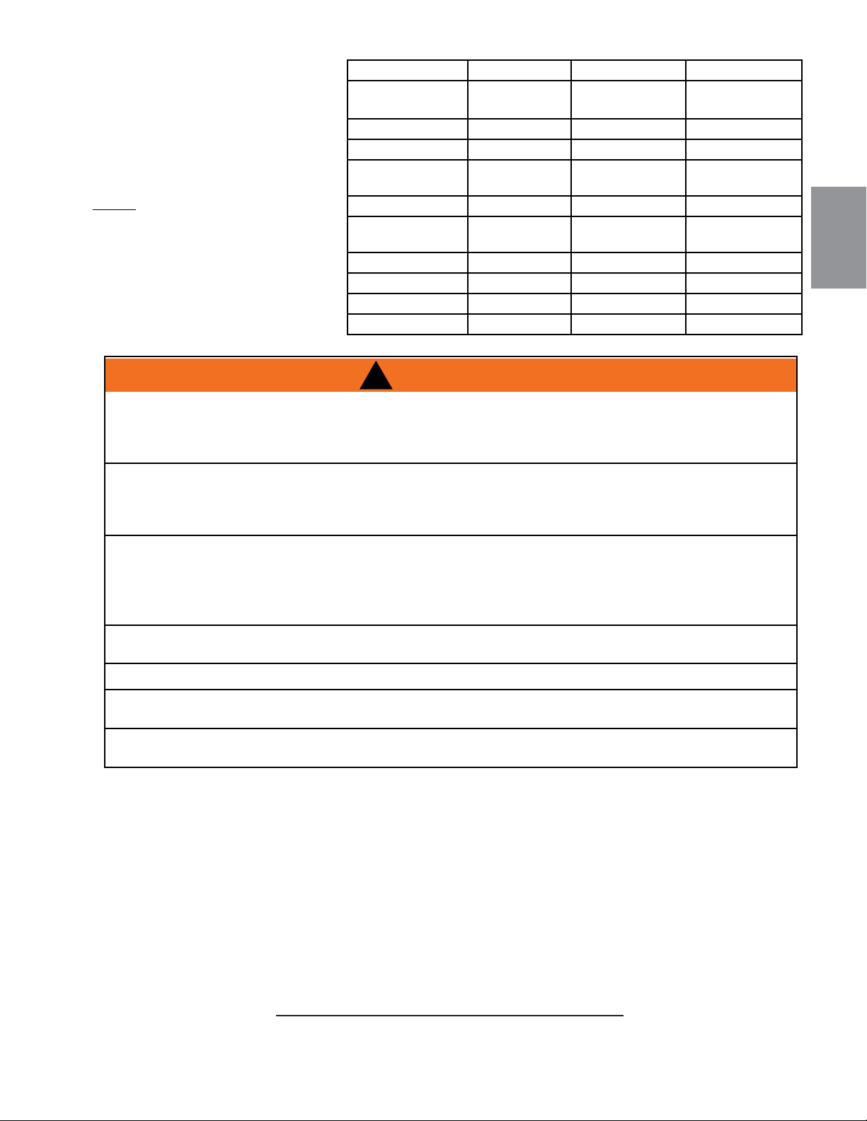
Model Number NEFB24HG NEFB27HG NEFB29HG
Description 24" Electric
Fireplace
27" Electric
Fireplace
29" Electric
Fireplace
Voltage 120V AC 120V AC 120V AC
Watts 1500W 1500W 1500W
Amps 15 AMP
Grounded
Circuit
15 AMP Ground-
ed Circuit
15 AMP Ground-
ed Circuit
Appliance Width 24" (610mm) 27" (686mm) 29" (737m)
Appliance Height 17 5/8"
(448mm)
18 5/8" (473mm) 20 1/8" (511mm)
Appliance Depth 8 5/8" (219mm) 9 1/2" (241mm) 9 1/2" (241mm)
Net Weight 31.1lbs (14.1kg) 35.9lbs (16.3kg) 36.4lbs (16.5kg)
Gross Weight (1A) 34.6lbs (15.7kg) 39.7lbs (18kg) 40.8lbs (18.5kg)
Gross Weight (3A) 37lbs (17kg) 44lbs (20kg) 45bs (20.5kg)
1.3 GENERAL INSTRUCTIONS
As with most electronic devices, your new electric fireplace has been designed to operate at temperatures
between 5°C (41°F) and 35° C (95°F). During the colder winter months, allow the fireplace to reach room
temperature before turning it on.
EN
W415-1662 / 05.17.16
6
1.4 RATING PLATE INFORMATION
W385-2154
CERTIFIED UNDER CANADIAN AND AMERICAN NATIONAL STANDARD: CSA 22.2 NO. 46 AND UL 2021 /
HOMOLOGUÉ SELON LES NORMES NATIONALES CANADIENNES ET AMÉRICAINES:CSA 22.2 NO. 46 UL 2021
Page 1 of 1
FOYER À ÉLECTRIQUE. HOMOLOGUÉ POUR
INSTALLATION DANS UNE CHAMBRE À
COUCHER, UNE SALLE DE BAIN ET UN STUDIO.
APPROPRIÉ POUR INSTALLATION DANS UNE
MAISON MOBILE.
ELECTRIC FIREPLACE. SUITABLE FOR
BEDROOM AND BED-SITTING ROOM
INSTALLATION. SUITABLE FOR MOBILE
HOME INSTALLATION.
VOLTAGE: 120 VAC TENSION: 120VCA
FREQUENCY: 60Hz FRÉQUENCE: 60Hz
POWER: 1500W PUISSANCE: 1500W
DATE CODE: XXXXX CODE DE DATE:
DESIGNED IN NORTH AMERCIA
BY WOLF STEEL LTD.
MADE IN CHINA
FABRIQUÉ EN CHINE
WOLF STEEL LTD.
24 NAPOLEON ROAD,
BARRIE, ON, L4M 0G8 CANADA
SERIAL NUMBER/NO. DE SÉRIE:
NEFB
MATERIAL: CLASS IIIA-2 PERMANENT LEXAN ADHESIVE LABEL, MINIMUM THICKNESS 0.1MM, 121°C (250°F) RATING
SPECIFICATION: BLACK LETTERING ON SILVER BACKGROUND. MINIMUM FONT SIZE TO BE MINIMUM OF 8.5 PT (3.2mm)
MAX OVERALL SIZE: 6" x 3"
SERIAL NUMBERS TO BE ASCENDING FROM NEFB24HG 019016
TITLE: RATING PLATE NEFB24HG
REVISION:
DWG#: W385-2154
DATE: 04.27.16_H.W.
MODEL / MODÈLE:
NEFB24HG
DESIGN AMÉRIQUE DU NORD
PAR WOLF STEEL LTÉE.
MASTER CONTRACT: 161746
CONTRAT-CADRE: 161746
INSTALLER: It is your responsibility to check off the appropriate box on the rating plate according to
the model of the appliance.
For rating plate location, see “LABEL LOCATION” section.
This illustration is for reference only. Refer to the rating plate on the appliance for accurate information.
NOTE: The rating plate must remain with the appliance at all times. It must not be removed.
SAMPLE
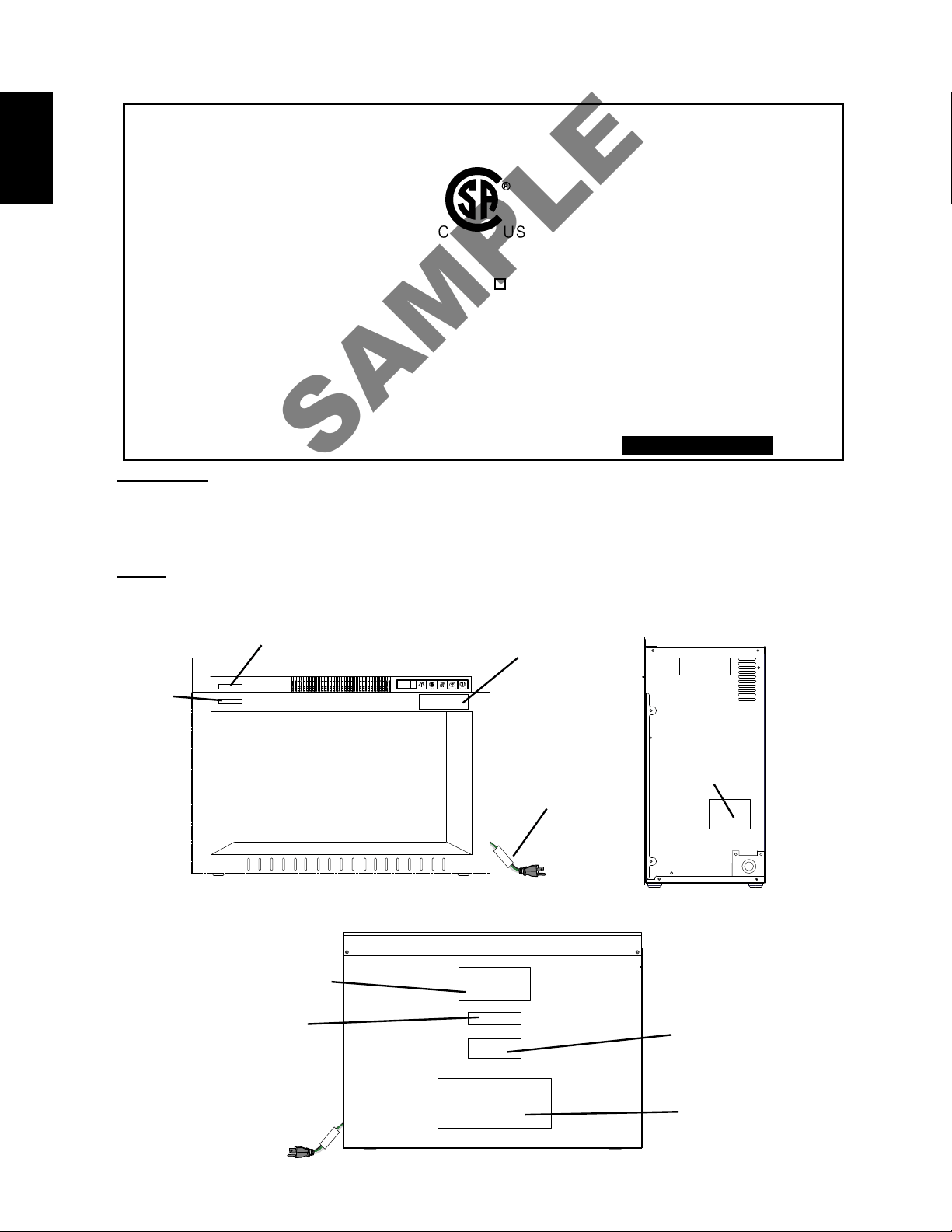
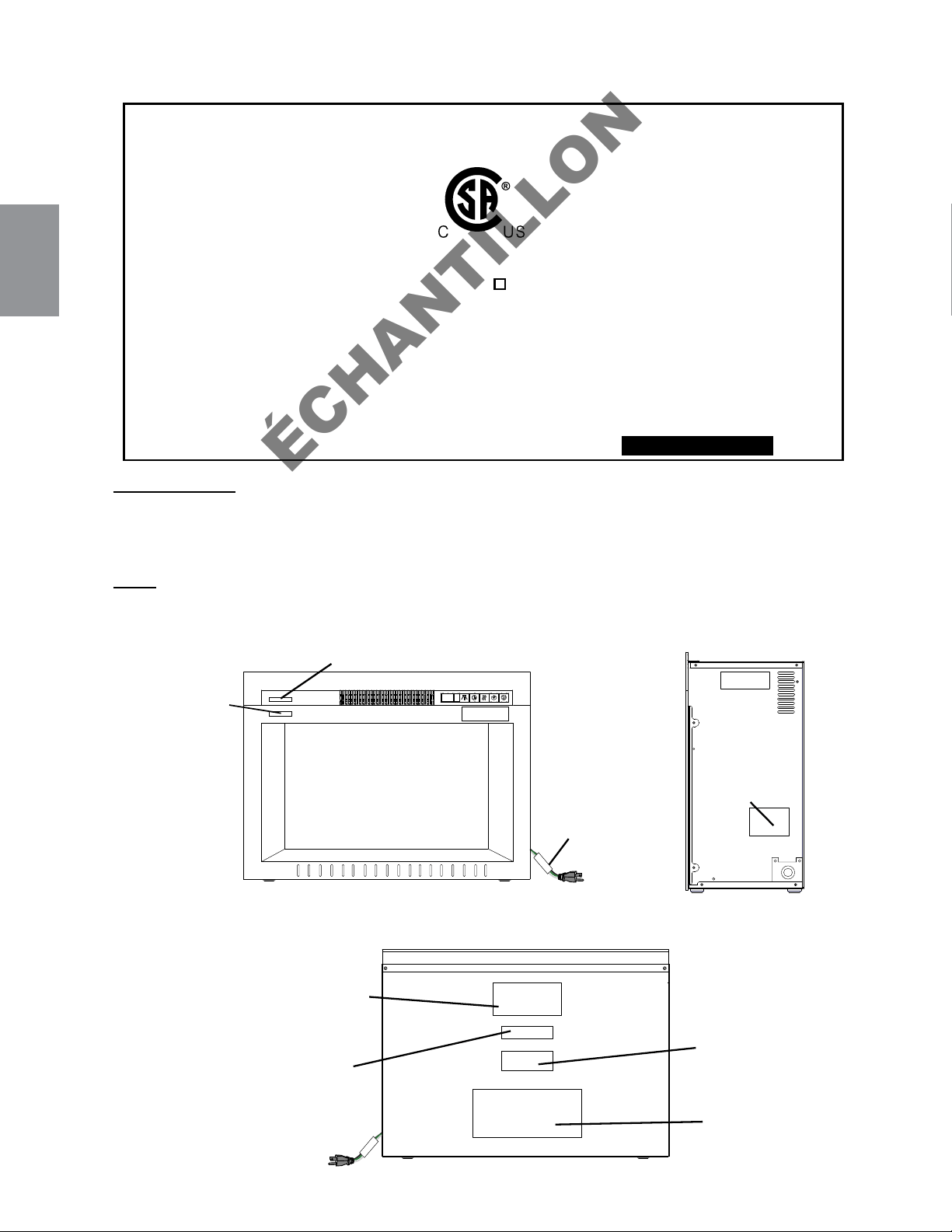
1.5 LABEL LOCATION
RATING PLATE WITH SERIAL
NUMBER
NEFB24HG (W385-2154)
NEFB27HG (W385-2155)
NEFB29HG (W385-2156)
WARNING LABEL
(W385-1944)
CAUTION LABEL
(W385-1945)
WIRE DIAGRAM LABEL
(W385-2157)
"DO NOT COVER" LABEL
(W385-1946)
HARD WIRING
LABEL
(W385-2003)
WARNING
LABEL
(W385-1943)
REAR
FRONT
SIDE
"HOT SURFACE"
LABEL
(W385-2017)
ATTENTION LABEL
(W385-2133)
EN
W415-1662 / 05.17.16
7
!
WARNING
2.0 LOCATING APPLIANCE
2.1 UNPACKING AND TESTING APPLIANCE
Carefully remove the appliance from the box and remove the support brackets. Prior to installing the
appliance, remove all packaging material and test to make sure the appliance operates properly by plugging
the power supply cord into a conveniently located 120V,15 Amp minimum grounded outlet.
2.2 GROUNDING APPLIANCE
DUE TO HIGH TEMPERATURES, THIS ELECTRIC APPLIANCE SHOULD BE LOCATED OUT OF
TRAFFIC. KEEP COMBUSTIBLE MATERIALS SUCH AS FURNITURE, PILLOWS, BEDDING, PAPERS,
CLOTHES AND CURTAINS AT LEAST 36" FROM THE FRONT OF THE APPLIANCE.
NEVER LOCATE THIS ELECTRIC APPLIANCE WHERE IT MAY FALL INTO A BATHTUB OR OTHER
WATER CONTAINER.
WEAR SAFETY GLOVES AND SAFETY GLASSES FOR PROTECTION DURING INSTALLATION AND
MAINTENANCE.
TO PREVENT CONTACT WITH SAGGING OR LOOSE INSULATION, THE ELECTRIC APPLIANCE
MUST NOT BE INSTALLED AGAINST VAPOR BARRIER OR EXPOSED INSULATION. LOCALIZED
OVERHEATING COULD OCCUR AND A FIRE COULD RESULT.
DO NOT EXPOSE THE ELECTRIC APPLIANCE TO THE ELEMENTS (SUCH AS RAIN, ETC.)
96.1
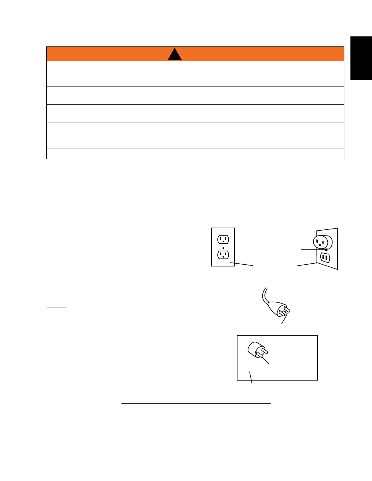
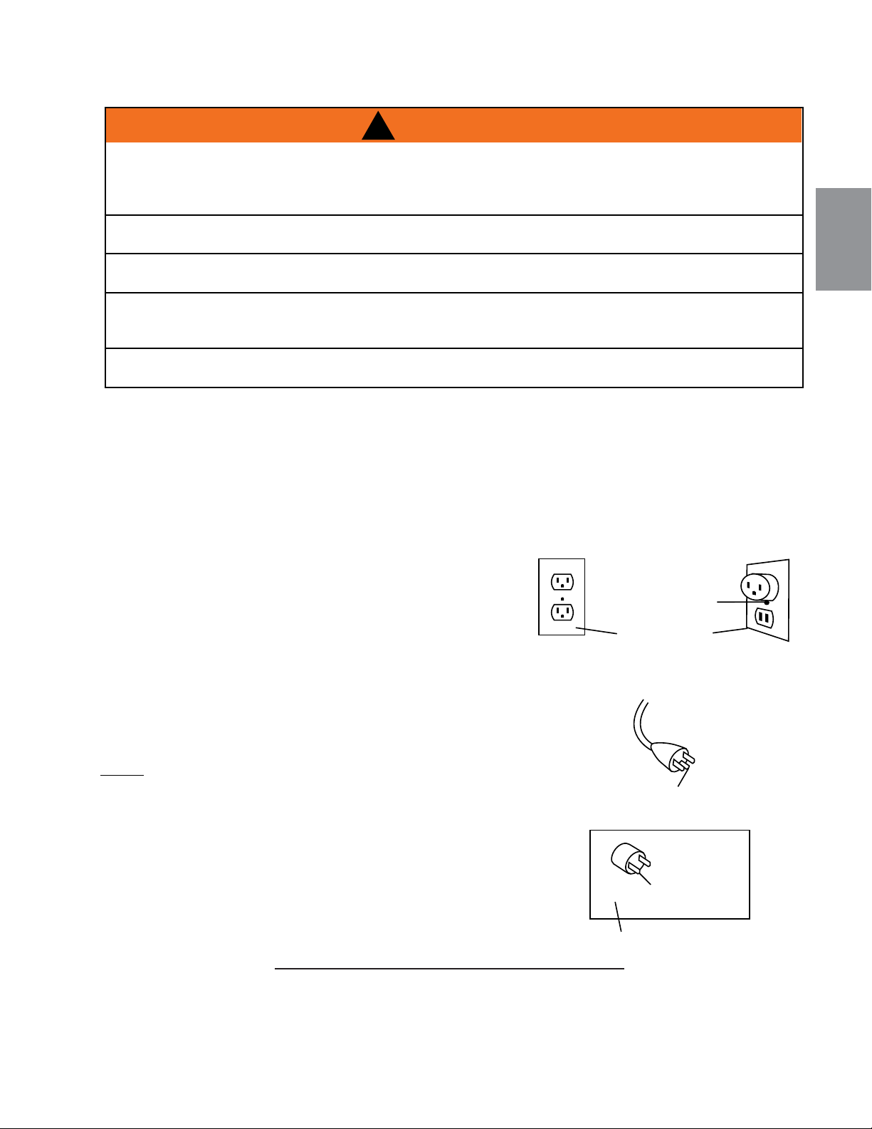
GROUNDING METHODS
METAL SCREW
(A)
NOT ALLOWED IN CANADA
GROUNDING
MEANS
ADAPTER
GROUNDING PIN
COVER OF
GROUNDED
OUTLET BOX
(C)
(B)
This appliance is for use on 120 volts. The cord has a plug
as shown in (A). An adapter as shown in (C) is available for
connecting three-blade grounding type plugs to two-slot
receptacles. The green grounding plug extending from the
adapter must be connected to a permanent ground such as
a properly grounded outlet box. The adapter should not be
used if a three-slot grounded receptacle is available.
To disconnect appliance, turn controls to off, then remove
plug from outlet.
NOTE: Must be connected to a dedicated15 amp circuit. The
use of an extension cord is NOT permitted.
EN
W415-1662 / 05.17.16
8
3.0 INSTALLATION
Select a suitable location that is not susceptible to moisture and is away from drapes, furniture and high
traffic areas.
NOTE: Follow all National and local electrical codes.
!
WARNING
RISK OF FIRE! THE POWER CORD MUST NOT BE PINCHED AGAINST A SHARP EDGE. SECURE CORD TO AVOID
TRIPPING OR SNAGGING TO REDUCE THE RISK OF FIRE, ELECTRIC SHOCK OR PERSONAL INJURY. DO NOT RUN
CORD UNDER CARPETING. DO NOT COVER CORD WITH THROW RUGS, RUNNERS OR THE LIKE. ARRANGE CORD
AWAY FROM TRAFFIC AREAS AND WHERE IT WILL NOT BE TRIPPED OVER.
RISK OF FIRE! TO PREVENT A POSSIBLE FIRE, DO NOT BLOCK AIR INTAKE OR EXHAUST IN ANY MANNER. DO NOT
USE ON SOFT SURFACES WHERE OPENINGS MAY BECOME BLOCKED.
RISK OF FIRE! DO NOT BLOW OR PLACE INSULATION AGAINST THE APPLIANCE.
THIS ELECTRIC APPLIANCE IS TESTED AND LISTED FOR USE ONLY WITH THE APPROVED OPTIONAL ACCESSORIES.
USE OF OPTIONAL ACCESSORIES NOT SPECIFICALLY TESTED FOR THIS ELECTRIC APPLIANCE COULD VOID THE
WARRANTY AND/OR RESULT IN A SAFETY HAZARD.
IF THE INFORMATION IN THESE INSTRUCTIONS IS NOT FOLLOWED EXACTLY, A FIRE OR EXPLOSION MAY RESULT
CAUSING PROPERTY DAMAGE, PERSONAL INJURY OR DEATH. DO NOT STORE OR USE GASOLINE OR OTHER
FLAMMABLE VAPORS IN THE VICINITY OF THIS OR ANY OTHER APPLIANCE.
THIS APPLIANCE IS HEAVY. IT IS HIGHLY RECOMMENDED THAT TWO PEOPLE INSTALL THIS APPLIANCE.
HEATER VENTS ON THE ELECTRIC APPLIANCE CANNOT, IN ANY WAY, BE COVERED AS IT MAY CREATE A FIRE
HAZARD.
DO NOT RUN THE POWER CORD HORIZONTALLY, DIRECTLY BELOW THE APPLIANCE.
68.5A
3.1 MINIMUM CLEARANCE TO COMBUSTIBLES
Measurements are taken from the glass front.
Bottom 0" Top 0" to 2" (51mm) mantel
Sides 1/4" (6.3mm) Top 3" (76mm) to ceiling
Back 1/4" (6.3mm) Top 1/4" (6.4mm) to enclosure
!
WARNING
WHEN USING PAINT OR LACQUER TO FINISH THE MANTEL, THE PAINT OR LACQUER MUST BE
HEAT RESISTANT TO PREVENT DISCOLOURATION.
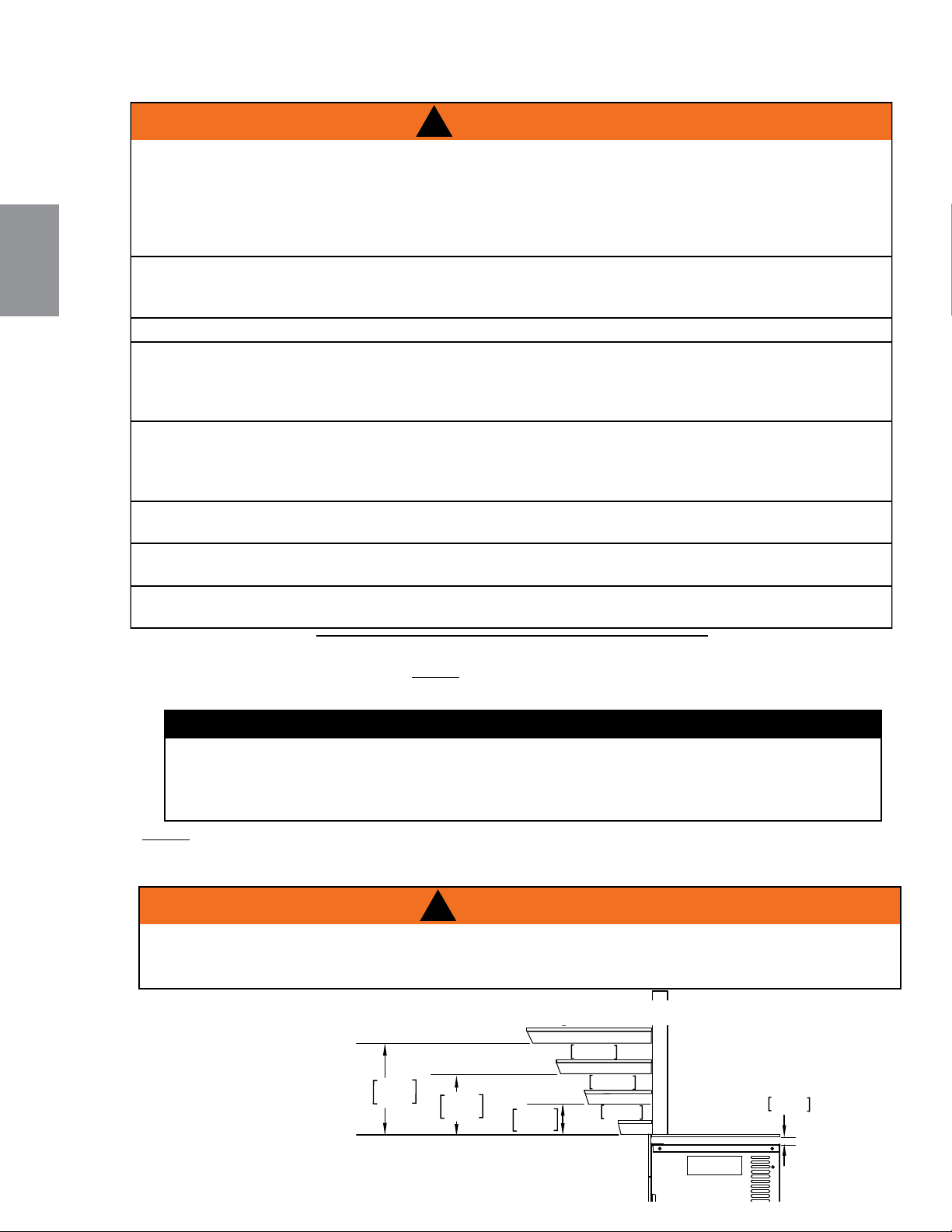
3.2 MINIMUM MANTEL CLEARANCES
NOTE: The control panel switch is located on the upper right hand side of the appliance. Always ensure
this switch remains accessible.
TOP OF APPLIANCE
6"
152mm
8"8"
203mm
MANTEL
1"
25mm
2"
51mm
3"
76mm
4"
102mm
2"
51mm
1/4"
6.3mm
EN
W415-1662 / 05.17.16
9
A. Once the rough opening has been
prepared, and the power has been
routed to the right side of the recess,
the appliance may be installed.
B. The electrical connection must be
made prior to placing the appliance
into position. (See "HARD WIRING
INSTALLATION" section).
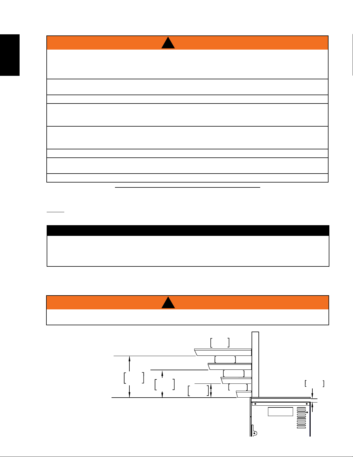
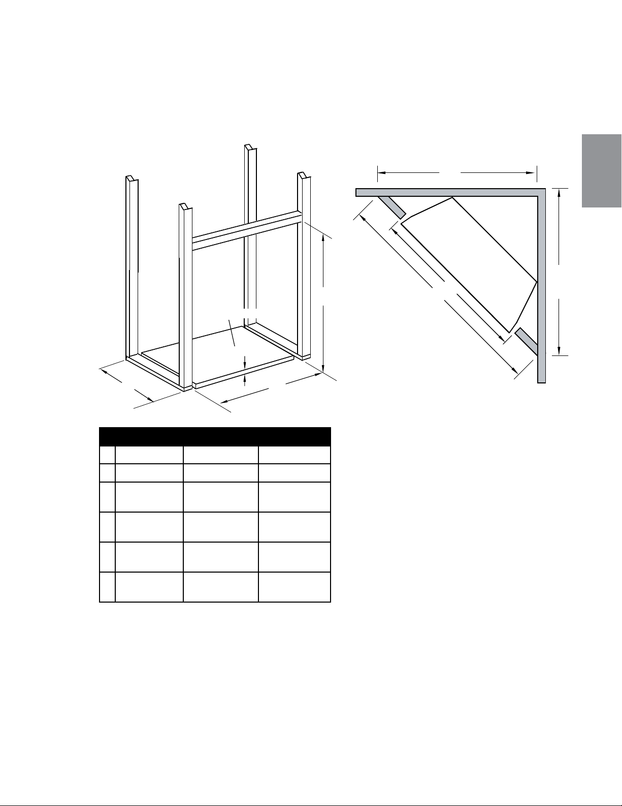
Prepare rough in framing following the recommended dimensions in Figure 1. For the corner rough in
framing, follow the recommended dimension in Figure 2.
Select a location that is not prone to moisture and is located at least 36" (914mm) away from combustible
materials such as curtain drapes, furniture, bedding, paper etc.
NEFB24HG NEFB27HG NEFB29HG
A
9" (229mm)
10" (254mm) 10" (254mm)
B
23" (584mm)
26" (660mm) 28" (711mm)
C
17 1/4"
(438mm) + F
18 1/4"
(463mm) + F
19 3/4"
(502mm) + F
J
41"
(1041mm)
44" (1118mm) 46" (1168mm)
K
29" (736mm) 31 1/2"
(800mm)
32 1/2"
(826mm)
L
29" (736mm) 31 1/2"
(800mm)
32 1/2"
(826mm)
L
K
J
B
C
B
A
L
K
J
B
C
B
A
F
FLOOR
(Or mantel base thickness)
Fig. 1
Fig. 2
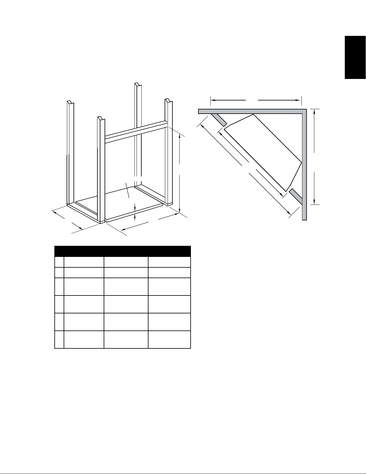
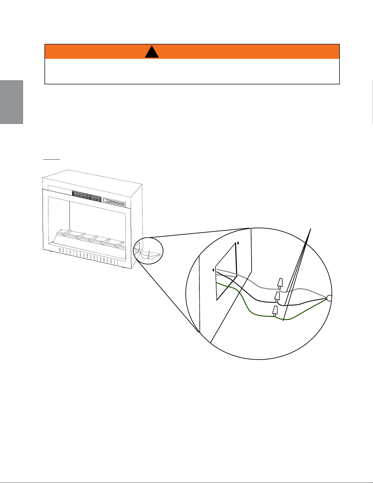
3.3 FRAMING
A. Remove the securing screw from the electrical cover plate, located on the right hand side of the
fireplace.
B. Add an electrical box connector and feed the supply wires through the 7/8" (22mm) hole.
C. Separate the black, white and green wires that have the wire nuts on them.
D. Remove the wire nuts and secure the black wire (power L1) to the black (power L1) lead of the
power supply. Connect the white wire from the unit to the white (neutral) wire from the power
supply. Connect the green wire to the ground wire.
E. Resecure the cover plate.
EN
W415-1662 / 05.17.16
10
GREEN
BLACK
WHITE
HARD WIRING CONNECTION
If it is necessary to hard wire this appliance, a qualified electrician must remove the cord connection, and
wire the appliance directly to the household wiring. The wire and power supply breaker must rated for 120V
minimum 15 Amps.
This appliance must be electrically connected and grounded in accordance with local codes, if hard wired.
In the absence of local codes, use the current CSA C22.1 CANADIAN ELECTRICAL CODE in Canada or the
current ANSI/NFPA 70 NATIONAL ELECTRICAL CODE in the United States.
!
WARNING
TURN OFF THE APPLIANCE COMPLETELY AND LET COOL BEFORE SERVICING. ONLY A QUALIFIED
SERVICE PERSON SHOULD SERVICE AND REPAIR THIS ELECTRIC APPLAINCE.
GREEN
BLACK
WHITE
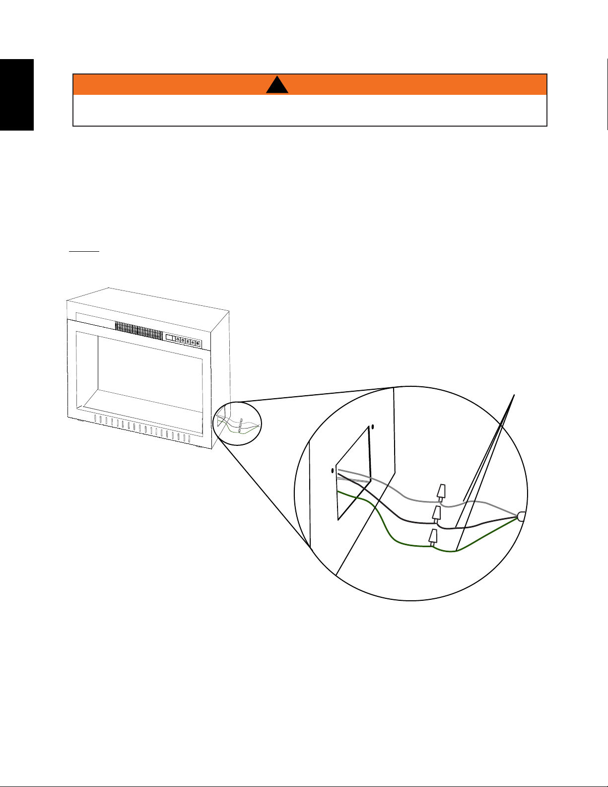
NOTE: There are 3 wires from the fireplace junction; white (neutral), black (power L1) and green
(ground) that connect to 120V power supply (breaker panel), see below.
White, Green and
Black wires:
Connect to 120V
power supply.
3.3.1 HARD WIRING INSTALLATION
* NEFB29HG ILLUSTRATED
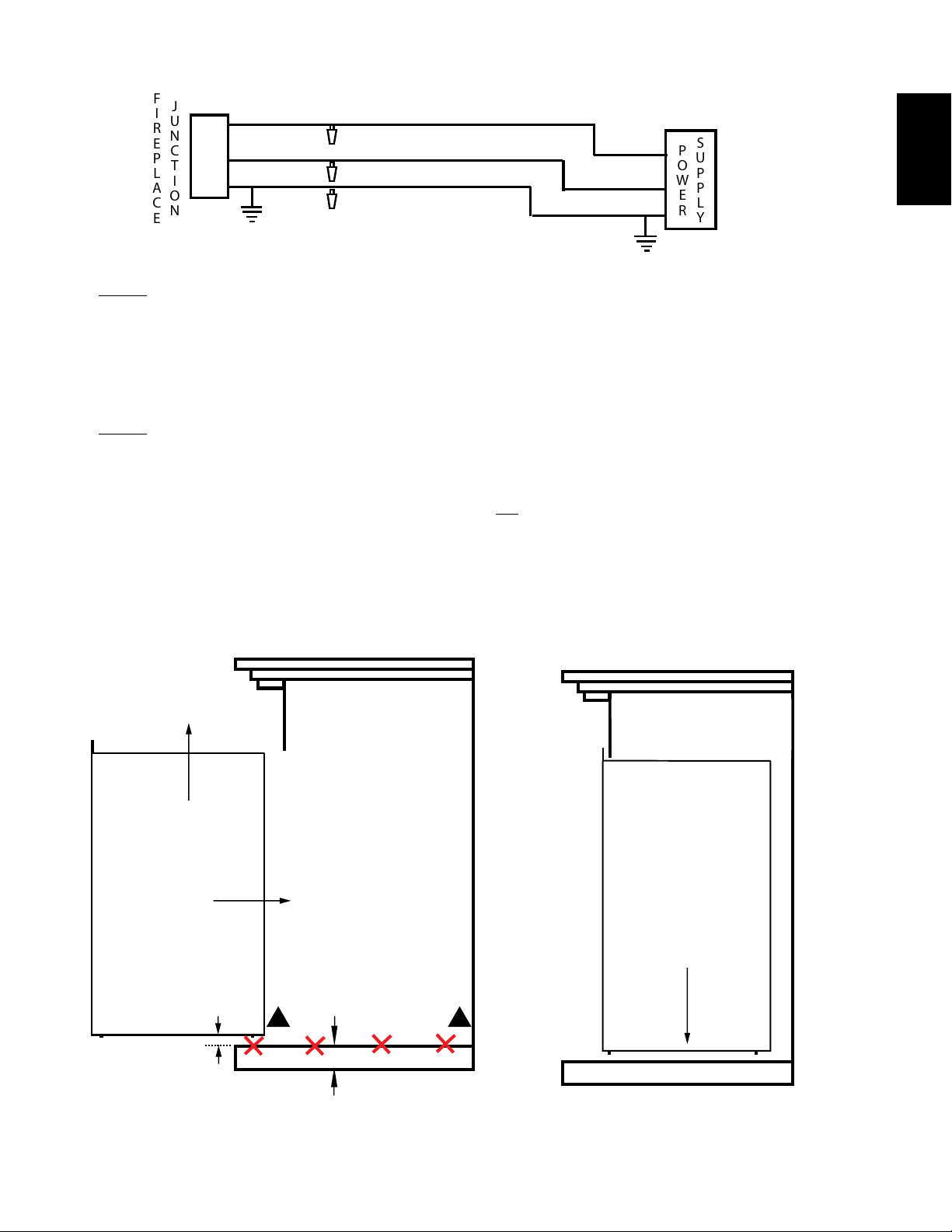
NOTE: To aid with moving the appliance, leave enough wire so that the appliance can be removed
from the enclosure without disconnecting the power supply. If servicing, shut off power supply.
BLACK
WHITE
BLACK
WHITE
SUPPLY
POWER
JUNCTION
FIREPLACE
GREEN
GREEN
JUNCTION
FIREPLACE
GROUND
BLACK
BLACK
BLACK
WHITE
WHITE
WIRE NUT
WALL
SWITCH
POWER
SUPPLY
JUNCTION
FIREPLACE
MARRET
RED
RED
RED
RED
GREEN
GREEN
THERMOSTAT
(L1)
(N)
(G)
WIRE NUT
(L1)
(N)
(L1)
(N)
Fig. 1
Fig. 2
EN
W415-1662 / 05.17.16
11
3.3.2 APPLIANCE INSTALLATION
A. With two people, lift the appliance up and insert into the opening, keeping a 3/8" (9.5mm) space
between the appliance and floor base in order to not scratch the floor surface. Do not push or slide
the bottom of the appliance on the floor base, see Figure 1.
B. Set the appliance down and into place, see Figure 2.
C. If the appliance does not sit flat on the floor or mantel base, apply a shim (not supplied) under the
nylon pads and adjust until level.
MANTEL
TABLETTE
APPLIANCE
APPAREIL
1/4"
MANTEL
TABLETTE
APPLIANCE
APPAREIL
STEP 1: LIFT
ÉTAPES 1: SOULEVER
STEP 2: INSERT
ÉTAPES 2: INSÉREZ
STEP 3: SET APPLIANCE
ÉTAPES 3: RÉGLÉ APPAREIL
DO NOT SLIDE APPLIANCE
NE GLISSEZ PAS L'APPAREIL
!
!
MANTEL
TABLETTE
APPLIANCE
APPAREIL
1/4"
MANTEL
TABLETTE
APPLIANCE
APPAREIL
STEP 1: LIFT
ÉTAPES 1: SOULEVER
STEP 2: INSERT
ÉTAPES 2: INSÉREZ
STEP 3: SET APPLIANCE
ÉTAPES 3: RÉGLÉ APPAREIL
DO NOT SLIDE APPLIANCE
NE GLISSEZ PAS L'APPAREIL
!
!
MANTEL
MANTEL
F
NOTE: This appliance is equipped with nylon pads located on the bottom four corners. To prevent
damaging the base of the mantel, carefully lift the appliance into the mantel while avoiding contact
with the front edge of the mantel base.
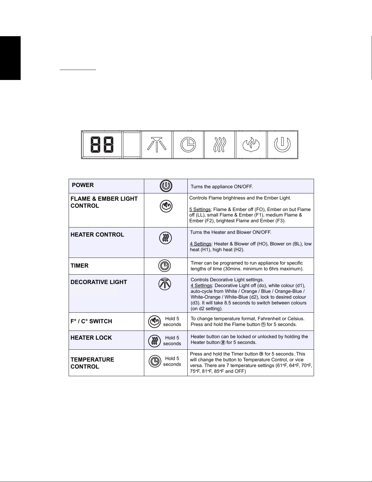
POWER
Turns the appliance ON/OFF.
FLAME & EMBER LIGHT
CONTROL
HEATER CONTROL
DECORATIVE LIGHT
(CEFB29H ONLY)
TIMER
TEMPERATURE
CONTROL
Controls Flame brightness and the Ember Light.
5 Settings
: Flame & Ember off (FO), Ember on but Flame
off (LL), small Flame & Ember (F1), medium Flame &
Ember (F2), brightest Flame and Ember (F3).
Turns the Heater and Blower ON/OFF.
4 Settings: Heater & Blower off (HO), Blower on (BL), low
heat (H1), high heat (H2).
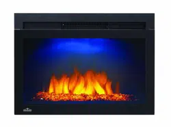
Controls Decorative Light settings.
4 Settings
: Decorative Light off (do), white colour (d1),
auto-cycle from White / Orange / Blue / Orange-Blue /
White-Orange / White-Blue (d2), lock to desired colour
(d3). It will take 8.5 seconds to switch between colours
(on d2 setting).
Timer can be programed to run appliance for specific
lengths of time (30mins. minimum to 6hrs maximum).
Press and hold the Timer button for 5 seconds. This
will change the button to Temperature Control, or vice
versa. There are 7 temperature settings (61
°F, 64°F, 70°
F,
75
°F, 81°F, 85°F and OFF)
F° / C° SWITCH
Hold 5
seconds
To change temperature format, Fahrenheit or Celsius.
Press and hold the Flame button for 5 seconds.
HEATER LOCK
Hold 5
seconds
Heater button can be locked or unlocked by holding the
Heater button for 5 seconds.
Hold 5
seconds
EN
W415-1662 / 05.17.16
12
4.0 OPERATING INSTRUCTIONS
Once the appliance has been plugged into a grounded electrical outlet or hard wired to a dedicated 120V
power supply, it is ready to operate.
ATTENTION: Ensure the house circuit breakers for the power supply are turned on. When initially
connecting the appliance into a power source the unit will perform an LED check. The unit will flash on
and off for 5 seconds.
The Control Panel is located on the top front of the appliance.
4.1 OPERATING CONTROL PANEL
EN
W415-1662 / 05.17.16
13
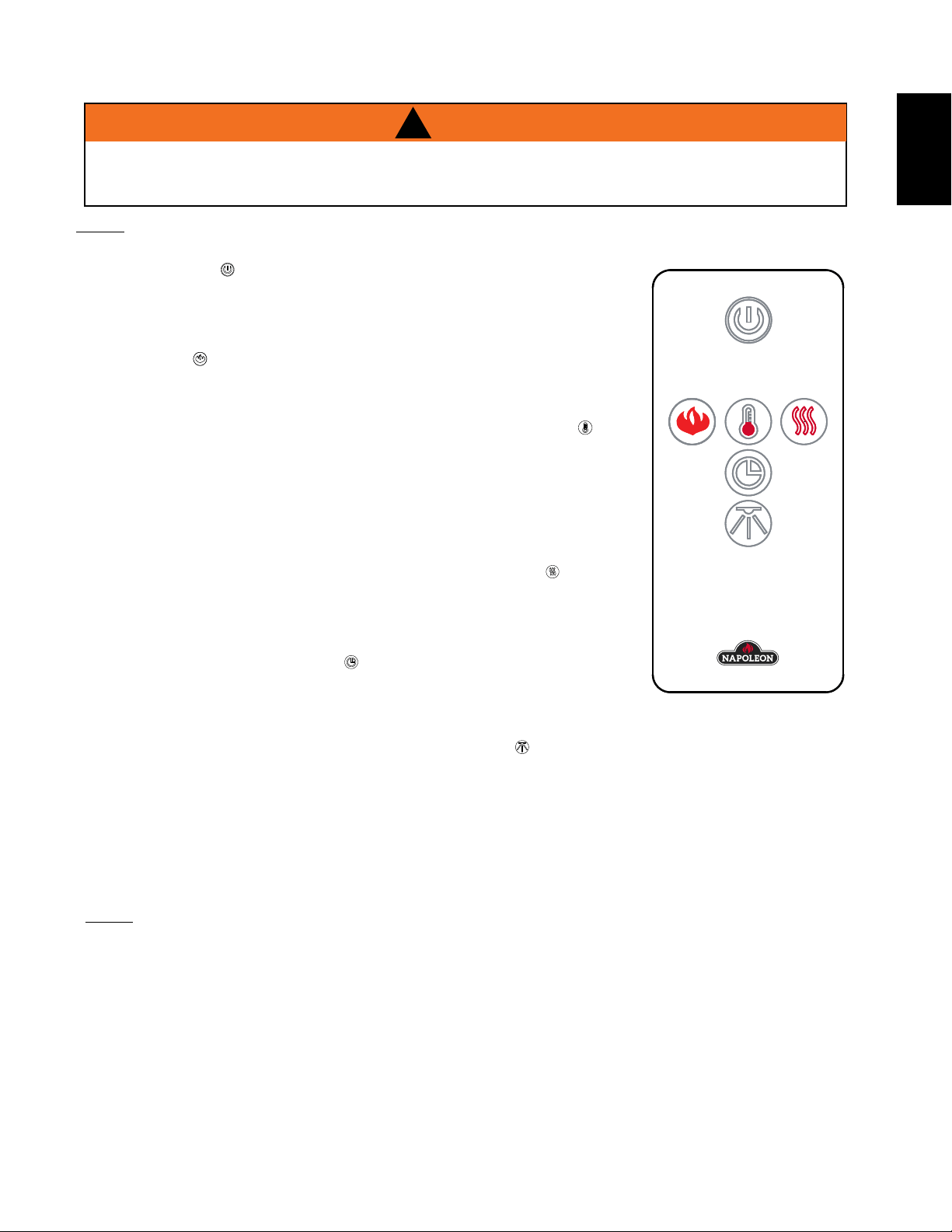
4.2 OPERATING BY REMOTE CONTROL
!
WARNING
TO AVOID DANGER OF SUFFOCATION KEEP THE PACKAGING BAG AWAY FROM BABIES AND
CHILDREN. DO NOT USE IN CRIBS, BED, CARRIAGES OR PLAY PENS. THIS BAG IS NOT A TOY.
KNOT BEFORE THROWING AWAY.
A. The power button can be used to turn the appliance on/off. Pressing
this button activates the power to the appliance. Pressing the power
button again will turn off the appliance. The ember and log will fade after
4 seconds after turning off the appliance.
B. To adjust the flame brightness and ember log light, press the flame
button . There is one ember log light and three flame brightness
levels to cycle through and then an off setting ( LL, F1, F2, F3 and then
F0).F3 is the brightest flame level, LL is the ember log light only.
C. To control the thermostat function press the thermostat button .
There are 7 temperature settings (61°F, 64°F, 70°F, 75°F, 81°F 85°F and
off). The default setting will display Fahrenheit. Press the thermostat
button to cycle through the settings. Once you have selected the
desired temperature the heater will automatically operate until that
temperature is reached. When the room temperature is 2 degrees lower
than the temperature setting, the heater will turn on.
D. To activate the heater and blower, press the heater button , the blower
will turn on. Press the heater button again to set desired low or high
heat temperature; press the heater button again to turn off the heater.
E. The timer controls all operating modes of the appliance. To activate the
timer, press the timer button , the icon will illuminate and the time
will appear on the LED display. To choose the desired time, continue to
press the timer button, there are 8 settings (30mins,1h, 2h, 3h, 4h, 5h,
6h and off). The fireplace will turn off at the setting time.
F. To activate the decoration light, press the light button .There are
three settings to cycle through and then an off setting (d1, d2, d3 and
then d0). d1 white colour, d2 colour cycles from White / Orange / Blue / Orange-Blue / White-Orange
/ White-Blue. It will take 8.5 seconds to switch from one colour to the next when in d2 setting, d3 will
lock to a desired colour.
G. To turn off the appliance, press the power button once on the remote, or press the power button once
on the control panel on the unit.
NOTE: This hand held remote control must remain within 6 meters or 19 feet of the appliance to be
effective.
NOTE: When operating the remote control, it must be directed towards the front center of the appliance.
EN
W415-1662 / 05.17.16
14
5.0 FINISHING
!
WARNING
POWER SUPPLY SERVICE MUST BE COMPLETED PRIOR TO FINISHING TO AVOID
RECONSTRUCTION.
HEAT VENTS AND AIR OPENINGS CANNOT BE COVERED IN ANY CIRCUMSTANCES.
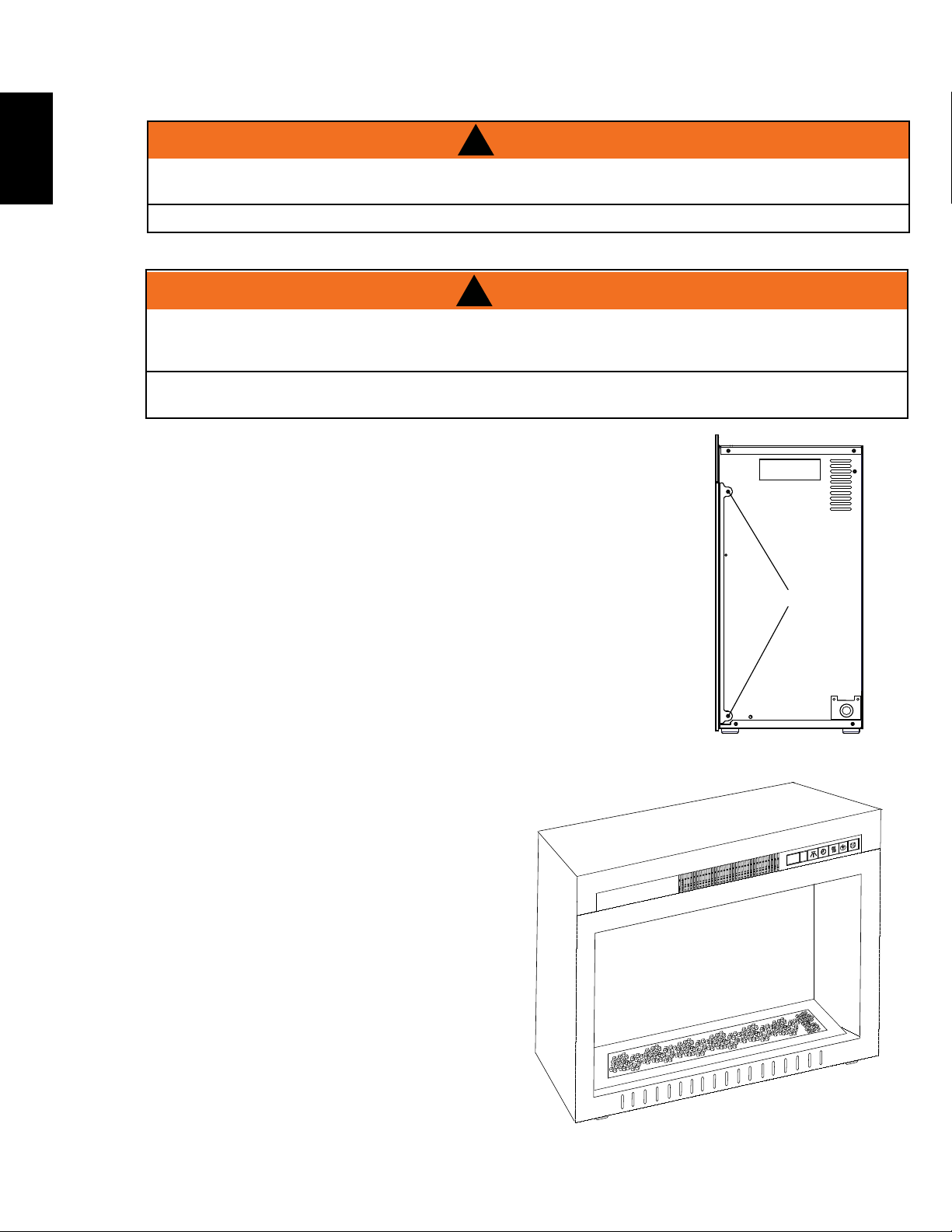
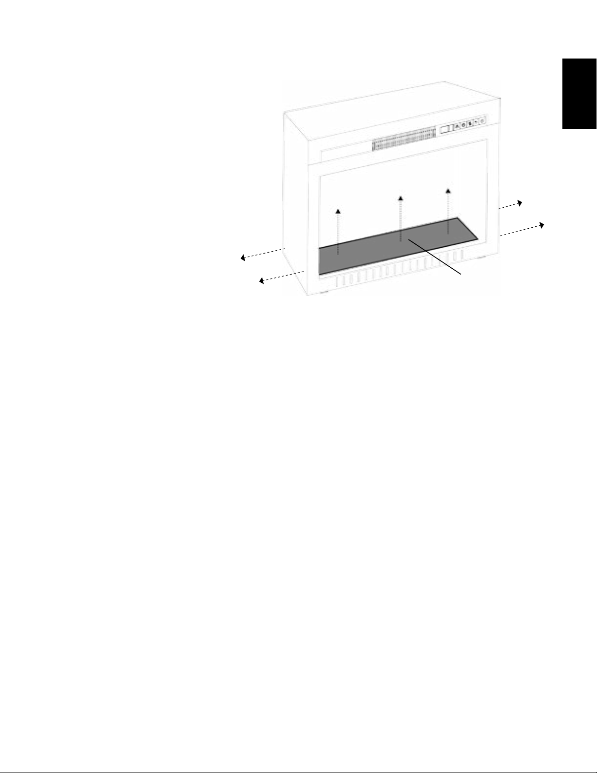
5.1 GLASS DOOR REMOVAL AND INSTALLATION
A. Remove the 4 screws off the appliance, as shown.
B. Remove the glass front and place on a soft non-
abrasive surface.
C. Reverse these steps to reinstall the glass front.
!
WARNING
FACING AND/OR FINISHING MATERIAL MUST NOT INTERFERE WITH AIR FLOW THROUGH
AIR OPENINGS, LOUVRES OPENINGS, OPERATION OF LOUVRES OR DOORS OR ACCESS FOR
SERVICE. OBSERVE ALL CLEARANCES WHEN APPLYING COMBUSTIBLE MATERIALS.
BEFORE DOOR IS REMOVED TURN THE APPLIANCE OFF AND WAIT UNTIL APPLIANCE IS COOL
TO THE TOUCH. DOORS ARE HEAVY AND FRAGILE SO HANDLE WITH CARE.
SCREW
5.2 PLACING GLASS MEDIA
A. Remove glass door, see "GLASS DOOR
REMOVAL AND INSTALLATION" section.
B. Sprinkle glass media evenly onto PVC tray.
Ensure glass media stays within the media tray
cavity.
EN
W415-1662 / 05.17.16
15
5.3 GLASS MEDIA EMBER BED ASSEMBLY REMOVAL
SCREW
EMBER
BED
* NEFB27HG ILLUSTRATED
A. Remove glass media from ember tray.
B. Remove the 4 screws, as shown.
C. Lift ember bed up from the appliance
and remove.
SCREW
EN
W415-1662 / 05.17.16
16
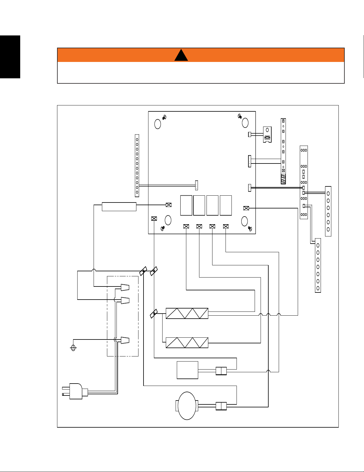
6.0 WIRING DIAGRAM
!
WARNING
TURN OFF THE APPLIANCE COMPLETELY AND LET COOL BEFORE SERVICING. ONLY A QUALIFIED
SERVICE PERSON SHOULD SERVICE AND REPAIR THIS ELECTRIC APPLAINCE.
TITLE: LABEL, WIRE DIAGRAM (NEFB24/27/29HG) PART #: W385-2157
REVISION:
DATE: 04.27.16_H.W.
MATERIAL: CLASS IIA-1 PERMANENT LEXAN ADHESIVE LABEL, MINIMUM THICKNESS 0.1MM,
TEMPERATURE RATING MINIMUM OF 121°C (250°F)
SPECIFICATION: BLACK LETTERING ON SILVER BACKGROUND
LABEL SIZE: 5 7/8" (150mm) x 4 3/8" (111mm)
PLUG /
FICHE
FAN /
SOUFFLERIE
MOTOR /
MOTEUR
AC-N
AC-L
RLY1 RLY2 RLY3 RLY4
NTC
OUTOUT
OUT
IN
#7
#8
#5
#6
#2 #4
#14
#1
#9
#3
#11
#12
#13
#10
#15
CARTE DE CIRCUIT IMPRIMÉ
MAIN PCB BOARD /
DECORATION /
DÉCORATION
L
N
G
WIRE NUT /
CONNECTEUR
DE FILS
WIRE NUT /
CONNECTEUR
DE FILS
WIRE NUT /
CONNECTEUR
DE FILS
HEATER 700W2 /
CHAUFFERETTE 700W2
HEATER 700W1 /
CHAUFFERETTE 700W1
THERMAL CUT-OFF /
COUPURE
THERMIQUE
DECORATION LIGHT (OPTIONAL) /
DECORATION DE LUMIÈRE(OPTIONNEL)
700W1
700W2
MOTOR /
MOTEUR
FAN /
SOUFFLERIE
T-FUSE /
FUSIBLE
FLAME /
FLAMME
DISPLAY CN3 /
AFFICHAGE
TEMPERATURE
SENSOR /
CAPTEUR DE
EMPÉRATURE
CONTROL PANEL BOARD /
PANNEAU DE CONTRÔLÉ
FLAME LED LIGHT /
LUMIÈRE DEL DE FLAMME
#1 EMBER BED LED /
LIT DE BRAISES DE DEL #1
W385-2157
#2 EMBER BED LED /
LIT DE BRAISES DE DEL #2
EN
W415-1662 / 05.17.16
17
Contact your dealer or the factory for questions concerning prices and
policies on replacement parts. Normally all parts can be ordered through
your Authorized dealer / distributor.
FOR WARRANTY REPLACEMENT PARTS, A PHOTOCOPY OF THE
ORIGINAL INVOICE WILL BE REQUIRED TO HONOUR THE CLAIM.
When ordering replacement parts always give the following information:
• Model and serial number of appliance
• Installation date of appliance
• Part number
• Description of part
• Finish
FOR FURTHER INFORMATION, CONTACT YOUR AUTHORIZED DEALER.
* PARTS, PART NUMBERS AND AVAILABILITY ARE SUBJECT TO CHANGE WITHOUT NOTICE.
41.1A
FAILURE TO POSITION THE PARTS
IN ACCORDANCE WITH THIS
MANUAL OR FAILURE TO USE ONLY
PARTS SPECIFICALLY APPROVED
WITH THIS APPLIANCE MAY
RESULT IN PROPERTY DAMAGE OR
PERSONAL INJURY.
!
WARNING
For after sales service, please call 1-866-820-8686
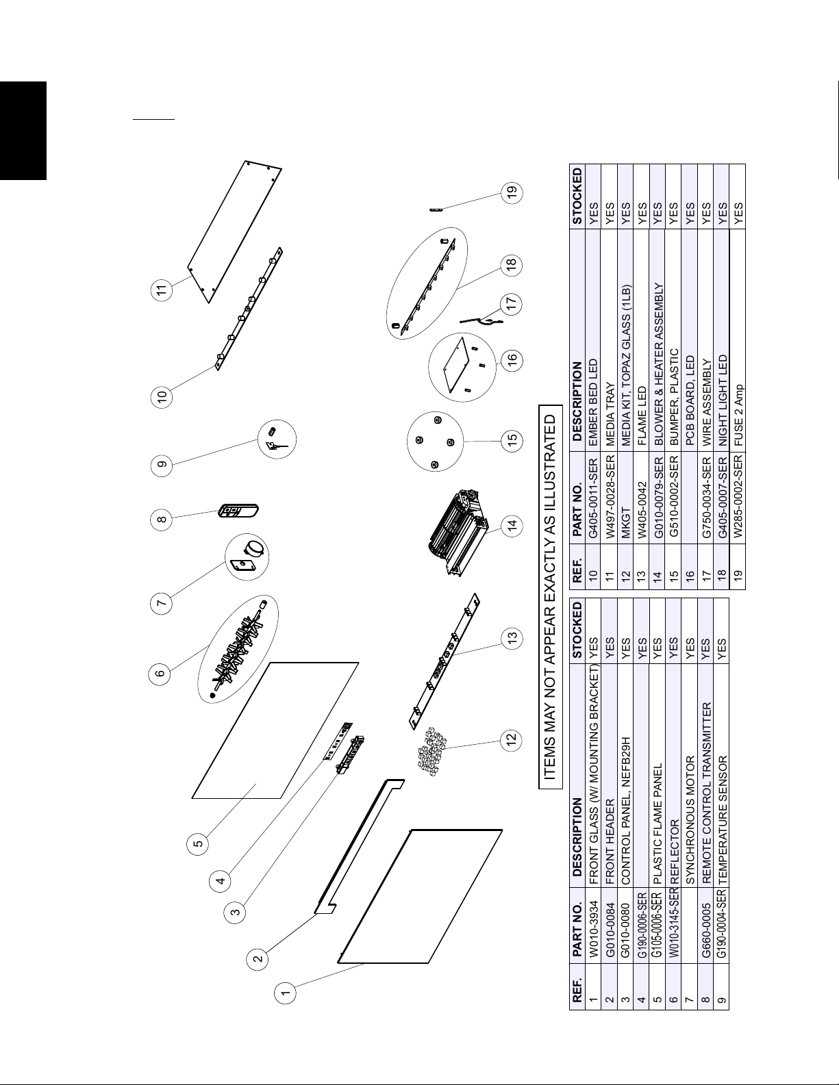
7.0 REPLACEMENT PARTS
EN
W415-1662 / 05.17.16
18
NOTE: Care must be taken when removing and disposing of any broken glass or damaged
components. Be sure to vacuum up any broken glass from inside the appliance before operation.
REF.
PART NO.
DESCRIPTION
1
2
3
4
5
6
7
8
REF.
PART NO.
DESCRIPTION
11
ITEMS MAY NOT APPEAR EXACTLY AS ILLUSTRATED
G105-0006-SER
FRONT GLASS (W/ MOUNTING BRACKET)
G010-0079-SER
W405-0042
G010-0084
W010-3934
G660-0005
W010-3145-SER
PLASTIC FLAME PANEL
BLOWER & HEATER ASSEMBLY
FLAME LED
REFLECTOR
REMOTE CONTROL TRANSMITTER
FRONT HEADER
W435-0059-SER
SYNCHRONOUS MOTOR
W190-0066-SER
PCB BOARD, LED
31
14
15
12
13
CONTROL PANEL, NEFB29H
G010-0080
32
CONTROL PANEL BOARD
33
34
35
3
6
3
7
8
9
10
13
14
2217
G750-0034-SER
WIRE ASSEMBLY
10
G405-0011-SER
EMBER BED LED
9
G190-0004-SER
TEMPERATURE SENSOR
16
G405-0007-SER
NIGHT LIGHT LED
18
17
18
W497-0028-SER
MEDIA TRAY
MKGT
MEDIA KIT, TOPAZ GLASS (1LB)
12
G190-0006-SER
G510-0002-SER
BUMPER, PLASTIC
3
15
3
16
19
W285-0002-SER
FUSE 2 Amp
11
19
STOCKED
STOCKED
YES
YES
YES
YES
YES
YES
YES
YES
YES
YES
YES
YES
YES
YES
YES
YES
YES
YES
YES
7.1 NEFB24HG OVERVIEW
EN
W415-1662 / 05.17.16
19
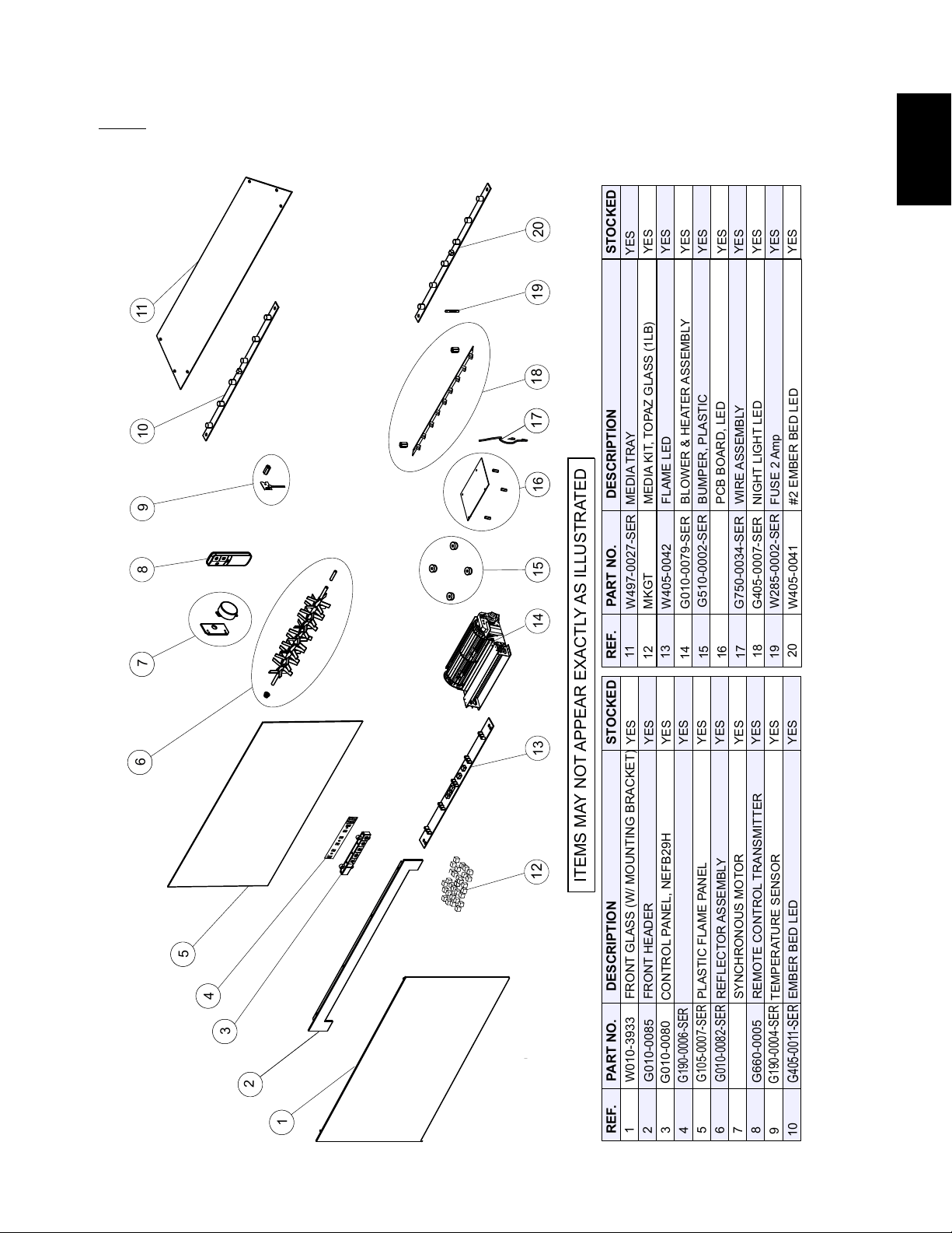
REF.
PART NO.
DESCRIPTION
1
2
3
4
5
6
7
8
REF.
PART NO.
DESCRIPTION
11
ITEMS MAY NOT APPEAR EXACTLY AS ILLUSTRATED
G105-0007-SER
FRONT GLASS (W/ MOUNTING BRACKET)
G010-0079-SER
W405-0042
G010-0085
W010-3933
G660-0005
G010-0082-SER
PLASTIC FLAME PANEL
BLOWER & HEATER ASSEMBLY
FLAME LED
REFLECTOR ASSEMBLY
REMOTE CONTROL TRANSMITTER
FRONT HEADER
W435-0059-SER
SYNCHRONOUS MOTOR
W190-0066-SER
PCB BOARD, LED
31
14
15
12
13
CONTROL PANEL, NEFB29H
G010-0080
3
2
CONTROL PANEL BOARD
33
34
35
3
6
3
7
8
9
10
13
14
2217
G750-0034-SER
WIRE ASSEMBLY
9
G190-0004-SER
TEMPERATURE SENSOR
16
G405-0007-SER
NIGHT LIGHT LED
18
17
18
W497-0027-SER
MEDIA TRAY
MKGT
MEDIA KIT, TOPAZ GLASS (1LB)
12
G190-0006-SER
G510-0002-SER
BUMPER, PLASTIC
3
15
3
16
19
W285-0002-SER
FUSE 2 Amp
11
19
STOCKED
STOCKED
20
10
G405-0011-SER
EMBER BED LED
20
W405-0041
#2 EMBER BED LED
YES
YES
YES
YES
YES
YES
YES
YES
YES
YES
YES
YES
YES
YES
YES
YES
YES
YES
YES
YES
NOTE: Care must be taken when removing and disposing of any broken glass or damaged
components. Be sure to vacuum up any broken glass from inside the appliance before operation.
7.2 NEFB27HG OVERVIEW
EN
W415-1662 / 05.17.16
20
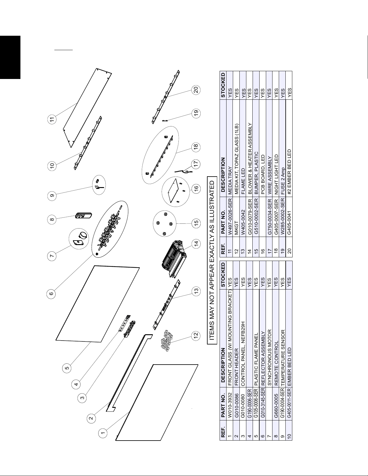
REF.
PART NO.
DESCRIPTION
1
2
3
4
5
6
7
8
REF.
PART NO.
DESCRIPTION
11
ITEMS MAY NOT APPEAR EXACTLY AS ILLUSTRATED
G105-0006-SER
FRONT GLASS (W/ MOUNTING BRACKET)
G010-0079-SER
W405-0042
G010-0086
W010-3932
G660-0005
G010-3145-SER
PLASTIC FLAME PANEL
BLOWER & HEATER ASSEMBLY
FLAME LED
REFLECTOR ASSEMBLY
REMOTE CONTROL
FRONT HEADER
W435-0059-SER
SYNCHRONOUS MOTOR
W190-0066-SER
PCB BOARD, LED
31
14
15
12
13
CONTROL PANEL, NEFB29H
G010-0080
3
2
CONTROL PANEL BOARD
33
34
35
3
6
3
7
8
9
10
13
14
2217
G750-0034-SER
WIRE ASSEMBLY
10
G405-0011-SER
EMBER BED LED
9
G190-0004-SER
TEMPERATURE SENSOR
16
G405-0007-SER
NIGHT LIGHT LED
18
17
18
W497-0026-SER
MEDIA TRAY
MKGT
MEDIA KIT, TOPAZ GLASS (1LB)
12
G190-0006-SER
G510-0002-SER
BUMPER, PLASTIC
3
15
3
16
19
W285-0002-SER
FUSE 2 Amp
11
19
STOCKED
STOCKED
20
20
G405-0041
#2 EMBER BED LED
YES
YES
YES
YES
YES
YES
YES
YES
YES
YES
YES
YES
YES
YES
YES
YES
YES
YES
YES
YES
NOTE: Care must be taken when removing and disposing of any broken glass or damaged
components. Be sure to vacuum up any broken glass from inside the appliance before operation.
7.3 NEFB29HG OVERVIEW
EN
W415-1662 / 05.17.16
21
8.0 TROUBLESHOOTING
TURN OFF THE APPLAINCE COMPLETELY AND LET COOL BEFORE SERVICING. ONLY A
QUALIFIED SERVICE PERSON SHOULD SERVICE AND REPAIR THIS ELECTRIC APPLIANCE.
SYMPTOM PROBLEM TEST SOLUTION
Dim or no fl ame Flame brightness not
selected
Flame LEDs are burnt out
Main PCB board burnt out
See “OPERATION” section.
Inspect the LED by selecting different brightness settings and
replace them if necessary.
Inspect the Main PCB Board and replace if necessary..
Ember bed is not
glowing or dimming
Brightness not selected
Ember LEDs are burnt out
Main PCB board burnt out
See “OPERATION” section.
Inspect the ember bed LEDs by selecting different brightness
settings and replace if necessary.
Inspect the Main PCB board and replace if necessary.
No warm air coming
out of appliance
Heater setting not selected
Heater has been locked out
Room temperature is higher
than the appliance setting (if it
is set to room temperature)
Heater has overheated
Heater is burnt out
See “OPERATION” section, heater includes multiple selections
such as blower only, no heat, 750W (low heat), 1500W (high
heat).
See “OPERATION” section, heater lockout.
Reset temperature setting.
Unplug power or turn off the circuit breaker, allow appliance to
cool for 15 minutes.
Inspect the blower and heater and replace it if necessary.
Appliance turns off
and will not turn on
House circuit breaker has
tripped
Appliance fuse has blown
Appliance has overheated
and safety thermal switch has
tripped
Reset house circuit breaker.
Replace the fuse.
Unplug power or turn off the circuit breaker, allow appliance to
cool for 15 minutes to reset the thermal switch, then plug in or
turn it on.
Appliance will not
come on when
switch is fl ipped to
ON
Appliance is not plugged into
an electrical outlet
Check plug and plug it in.
Hard wire connections are
not correct
Appliance has overheated
and safety thermal switch has
tripped
La carte de circuit est brûlé
See “HARD WIRE INSTALLATION” section.
Unplug power or turn off the circuit breaker, allow appliance to
cool for 15 minutes, then plug in or turn the breaker on.
Inspecter la carte de circuit et remplacez-les au besoin
Remote control
does not work
Low batteries
Remote receiver malfunction
Replace batteries in remote control.
Ensure remote receiver is not blocked.
Replace control panel.
Flame does not
move
Motor stalled/malfunctioned Cycle ON/OFF. If problems persists, consult dealer.
Heater shuts off
automatically
Room is too warm The heater has a built-in thermostat so it will shut off automatically
once the pre-set temperature is reached. It will also turn on
automatically if the room temperature drops below the pre-set
temperature.
!
AVERTISSEMENT
!
AVERTISSEMENT
!
42.37
EN
W415-1662 / 05.17.16
22
LED Flashing Appliance has overheated and
safety thermal switch has tripped
Unplug power or turn off the circuit breaker, allow
appliance to cool for 15 minutes, then plug in or turn the
circuit breaker on.
Power Failure Appliance has returned to default
settings
Re-program appliance to original settings.
E1 Error Code Thermostat wire not connected to
PCB
Thermostat wire connection to PCB
is loose
Thermostat has failed
Connect wire.
Connect wire fi rmly to PCB.
Replace thermostat.
E2 Error Code Thermostat shorting
PCB thermostat connection is
shorting
Replace thermostat.
Replace PCB.
SYMPTOM PROBLEM TEST SOLUTION
42.37
EN
W415-1662 / 05.17.16
23
NAPOLEON warrants its products against manufacturing defects to the original purchaser only. Registering your warranty is not necessary.
Simply provide your proof of purchase along with the model and serial number to make a warranty claim. NAPOLEON reserves the right to have
its representative inspect any product or part thereof prior to honouring any warranty claim. Provided that the purchase was made through an
authorized NAPOLEON dealer, your appliance is subject to the following conditions and limitations:
Warranty coverage begins on the date of original installation.
This factory warranty is non-transferable and may not be extended whatsoever by any of our representatives.
Installation must be done in accordance with the installation instructions included with the product and all local and national building and fi re codes.
This limited warranty does not cover damages caused by misuse, lack of maintenance, accident, alterations, abuse or neglect and parts installed
from other manufacturers will nullify this warranty.
This limited warranty further does not cover any scratches, dents, corrosion or discolouring caused by excessive heat, abrasive and chemical
cleaners nor chipping on porcelain enamel parts, mechanical breakage of PHAZER™ logs.
In the fi rst year only, this warranty extends to the repair or replacement of warranted parts which are defective in material or workmanship,
provided that the product has been operated in accordance with the operation instructions and under normal conditions.
NAPOLEON will not be responsible for installation, labour or any other expenses related to the reinstallation of a warranted part, and such
expenses are not covered by this warranty. Notwithstanding any provisions contained in the Limited Warranty, NAPOLEON’s responsibility under
this warranty is defi ned as above, and it shall not in any event extend to any incidental, consequential or indirect damages.
This warranty defi nes the obligations and liability of NAPOLEON with respect to the NAPOLEON electric appliance and any other warranties
expressed or implied with respect to this product; its components or accessories are excluded.
NAPOLEON neither assumes, nor authorizes any third party to assume, on its behalf, any other liabilities with respect to the sale of this product.
Any damages to appliance, brass trim or other component due to water, weather damage, long periods of dampness, condensation, damaging
chemicals or cleaners will not be the responsibility of NAPOLEON.
The bill of sale or copy will be required together with a serial number and a model number when making any warranty claims from your authorized
dealer. The warranty registration card must be returned within fourteen days to register the warranty.
NAPOLEON reserves the right to have its representative inspect any product or part thereof prior to honouring any warranty claim.
All parts replaced under the Limited Warranty Policy are subject to a single claim.
All parts replaced under the warranty will be covered for a period of 90 days from the date of their installation.
The manufacturer may require that defective parts or products be returned or that digital pictures be provided to support the claim. Returned
products are to be shipped prepaid to the manufacturer for investigation. If a product is found to be defective, the manufacturer will repair or
replace such defect.
Before shipping your appliance or defective components, your dealer must obtain an authorization number. Any merchandise shipped without
authorization will be refused and returned to sender.
Shipping costs are not covered under this warranty.
Additional service fees may apply if you are seeking warranty service from a dealer.
2.5C
NAPOLEON electric appliances are manufactured under the strict Standard of the world recognized
ISO 9001 : 2008 Quality Assurance Certifi cate.
NAPOLEON products are designed with superior components and materials and assembled by trained craftsmen who
take great pride in their work. Once assembled the complete appliance is thoroughly inspected by a qualifi ed technician
before packing to ensure that you, the customer, receive the quality product that you expect from NAPOLEON.
Electrical components and wearable parts such as fan/heater, motors, switches, nylon bearing components and remote
controls are covered and NAPOLEON will provide replacement parts free of charge during the fi rst year of limited warranty.
Light bulbs and fuses are NOT covered by the warranty.
Any labour related to warranty repair is not covered.
* Construction of models vary. Warranty applies only to components included with your specifi c appliance.
NAPOLEON ELECTRIC APPLIANCE LIMITED WARRANTY
CONDITIONS AND LIMITATIONS
ALL SPECIFICATIONS AND DESIGNS ARE SUBJECT TO CHANGE WITHOUT PRIOR NOTICE DUE TO ON-GOING PRODUCT IMPROVEMENTS.
NAPOLEON IS A REGISTERED TRADEMARK OF WOLF STEEL LTD.
9.0 WARRANTY
10.0 SERVICE HISTORY
43.1

EN
W415-1662 / 05.17.16
25
11.0 NOTES
44.1
Other Napoleon
®
Products
Fireplace Inserts • Charcoal Grills
• Gas Fireplaces • Waterfalls • Wood Stoves
Heating & Cooling • Electric Fireplaces • Outdoor Fireplaces • Gas Grills
Fireplaces / Heating & Cooling call: 705-721-1212 • Grills call: 705-726-4278
napoleonproducts.com
24 Napoleon Road, Barrie, Ontario, Canada L4M 0G8
214 Bayview Drive, Barrie, Ontario, Canada L4N 4Y8
103 Miller Drive, Crittenden, Kentucky, USA 41030
7200 Trans Canada Highway, Montreal, Quebec, Canada H4T 1A3
FR
W415-1662 / 05.17.16
27
1.16F
!
AVERTISSEMENT
!
AVERTISSEMENT
!
INSTALLATEUR : LAISSEZ CE MANUEL AVEC L’APPAREIL.
PROPRIÉTAIRE : CONSERVEZ CE MANUEL POUR CONSULTATION ULTÉRIEURE.
NE LAISSEZ PAS LES ENFANTS OU AUTRES INDIVIDUS À RISQUE SEULS À PROXIMITÉ DE L’APPAREIL
Wolf Steel Ltd., 24 Napoleon Rd., Barrie, ON, L4M 0G8 Canada /
103 Miller Drive, Crittenden, Kentucky , USA, 41030
Téléphone 705-721-1212 • Télécopieur 705-720-9081 • www.napoleonfoyers.com • [email protected]
CONSIGNES DE SÉCURITÉ
Si ces instructions ne sont pas suivies à
la lettre, un incendie pourraient s’ensuivre
causant des dommages matériels, des
blessures corporelles ou des pertes de vie.
- N’entreposez pas et n’utilisez pas d’essence
ou autres liquides et vapeurs infl ammables à
proximité de cet appareil ou tout autre appareil.
INSTRUCTIONS
D’INSTALLATION ET
D’OPÉRATION
10,00 $
HOMOLOGUÉ SELON LES NORMES NATIONALES CANADIENNES ET AMÉRICAINES: CSA C22.2 No-46 / UL 2021
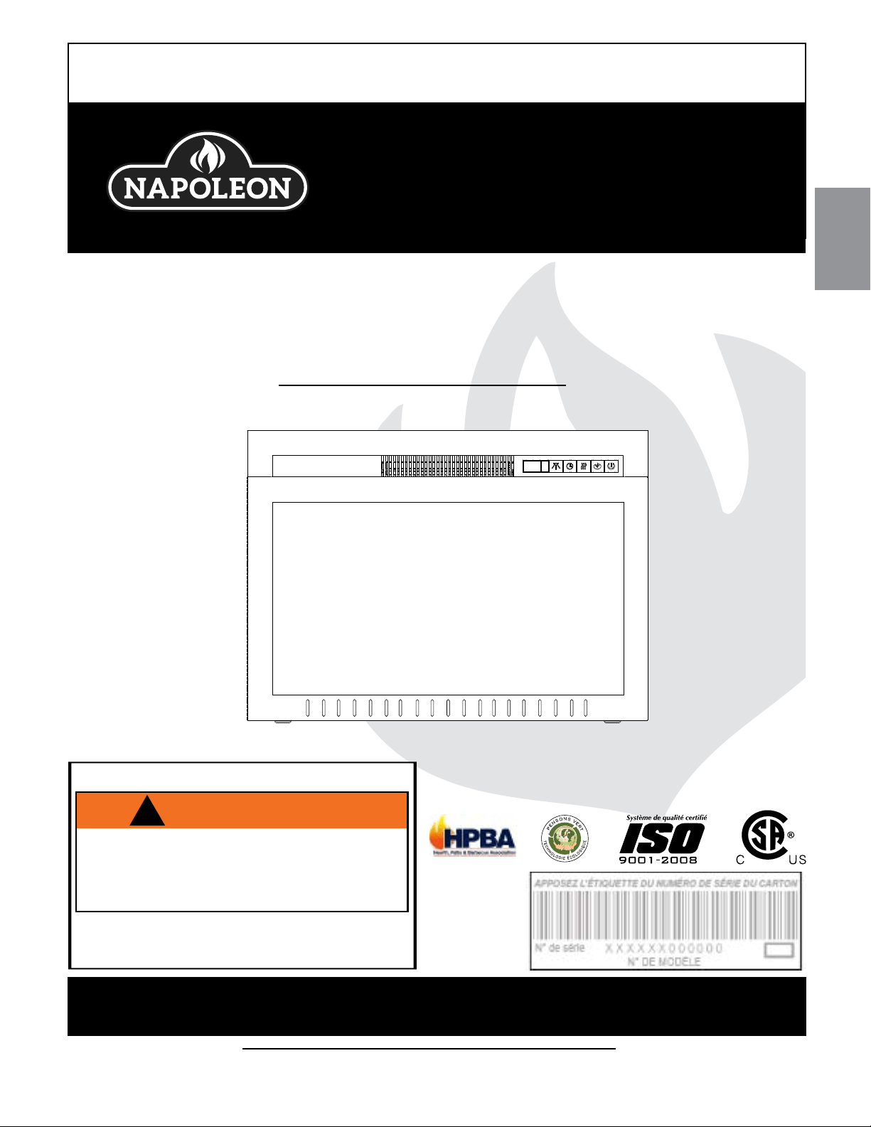
NEFB24HG, NEFB27HG &
NEFB29HG
FOYER ÉLECTRIQUE

FR
W415-1662 / 05.17.16
28
NOTE: Les changements autres que de nature éditoriale sont dénotés par une ligne verticale dans la marge.
TABLE DES MATIÈRES
1.0 INTRODUCTION 29
1.1 DIMENSIONS 30
1.3 INSTRUCTIONS GÉNÉRALES 31
1.2 HOMOLOGATIONS 31
1.4 PLAQUE D'HOMOLOGATION 32
1.5 EMPLACEMENT L'ÉTIQUETTE 32
2.0 EMPLACEMENT DE L'APPAREIL 33
2.1 DÉBALLAGE ET VÉRIFICATION DE L'APPAREIL 33
2.2 MISE À LA TERRE DE L'APPAREIL 33
3.0 INSTALLATION 34
3.1 DÉGAGEMENTS MINIMAUX AUX MATÉRIAUX COMBUSTIBLES 34
3.2 DÉGAGEMENTS MINIMAUX DE LA TABLETTE 34
3.3 OSSATURE 35
3.3.1 BRANCHEMENT PAR CABLE 36
3.3.2 INSTALLATION DE L'APPAREIL 37
4.0 INSTRUCTIONS DE FONCTIONNEMENT 38
4.1 INTERRUPTEUR ET PANNEAU DE COMMANDE 38
4.2 UTILISATION DE LA TÉLÉCOMMANDE 39
5.0 FINITIONS 40
5.1 ENLÈVEMENT ET INSTALLATION DE LA PORTE VITRÉE 40
5.2 PLACER LA BRAISES VITRIFIÉES 40
5.3 RETRAIT DE L'ENSEMBLE DE LA GRILLE DU LIT DE BRAISES 41
6.0 SCHÉMA DE CÂBLAGE 42
7.0 RECHANGES 43
7.1 VUE D'ENSEMBLE NEFB24HG 44
7.2 VUE D'ENSEMBLE NEFB27HG 45
7.3 VUE D'ENSEMBLE NEFB29HG 46
8.0 GUIDE DE DÉPANNAGE 47
9.0 GARANTIE 49
10.0 HISTORIQUE D'ENTRETIEN 50
11.0 NOTES 51
Les piles doivent être mises au rebut conformément aux lois et à la réglementation locales. Certaines piles
peuvent être recyclées dans votre centre de recyclage local. Renseignez-vous auprès de votre municipal-
ité au sujet des directives de recyclage.
FR
W415-1662 / 05.17.16
29
1.0 INTRODUCTION
3.7C
!
AVERTISSEMENT
!
AVERTISSEMENT
!
• CET APPAREIL EST CHAUD LORSQU’IL FONCTIONNE ET PEUT CAUSER DE GRAVES BRÛLURES EN CAS DE
CONTACT.
• Ne faites pas fonctionner l’appareil avant d’avoir lu et compris les instructions d’utilisation. Ne pas respecter les
instructions pourrait causer un incendie ou des blessures corporelles.
• Risque de brûlures. L’appareil doit être éteint et refroidi avant d’effectuer l’entretien. Pour débrancher l’appareil, mettez
d’abord les boutons de contrôle à « OFF » puis retirez la fi che de la prise de courant.
• N’installez pas de composants endommagés ou incomplets ni des composants de substitution.
• Ne brûlez pas de bois ou autres matériaux dans cet appareil.
• Les jeunes enfants doivent être supervisés attentivement lorsqu’ils sont dans la même pièce que l’appareil. Les jeunes
enfants et autres personnes sont sujets aux brûlures accidentelles. Une barrière de protection est recommandée s’il
y a dans la maison des individus à risque. Afi n de restreindre l’accès à l’appareil, installez une barrière de protection
ajustable pour garder les jeunes enfants ou autres personnes à risque hors de la pièce et loin des surfaces chaudes.
• Les vêtements et autres matériaux combustibles ne doivent pas être posés sur l’appareil ou à proximité.
• En raison des températures élevées, l’appareil devrait être placé loin des endroits passants et loin des meubles et des
rideaux.
• Assurez-vous de disposer de mesures de sécurité adéquates pour empêcher les jeunes enfants de toucher aux
surfaces chaudes.
• Même lorsque l’appareil est éteint, la porte et l’écran demeureront chauds pendant un bon moment.
• Consultez votre détaillant local de foyer pour connaître les grillages de sécurité et les écrans offerts pour protéger les
enfants des surfaces chaudes. Ces grillages de sécurité et ces écrans doivent être fi xés au plancher.
• Les grillages de sécurité ou écrans enlevés pour faire l’entretien devront être remis en place avant d’utiliser l’appareil.
• Il est primordial de garder propres les compartiments de contrôle, la souffl erie et les bouches d’air de l’appareil.
L’appareil doit être inspecté avant la première utilisation et au moins une fois l’an par un spécialiste en entretien. Un
entretien plus fréquent pourrait être nécessaire en raison des peluches provenant des tapis, literie, etc. L’emplacement
de l’appareil doit être gardé libre de tous matériaux combustibles, essence ou autres liquides et vapeurs infl ammables.
• Cet appareil ne devra être modifi é en aucun cas.
• N’utilisez pas cet appareil si une partie quelconque a été submergée. Contactez immédiatement un technicien
de service qualifi é pour inspecter l’appareil et pour remplacer toute pièce du système de contrôle qui aurait été
submergée.
• Ne pas opérer l’appareil lorsque la porte vitrée est enlevée, fi ssurée ou brisée. Le remplacement de la vitre devra être
effectué par un technicien de service certifi é ou qualifi é.
• Ne frappez pas et ne claquez pas la porte vitrée de l’appareil.
• Les matériaux d’emballage doivent être gardés hors de la portée des enfants et mis au rebut de façon sécuritaire.
Comme tous les emballages de plastique, ceux-ci ne sont pas des jouets et doivent demeurer hors de la portée des
enfants et des bébés.
• L’entretien ne doit être effectué que lorsque l’appareil est débranché du circuit électrique.
• Débranchez toujours l’appareil lorsqu’il n’est pas utilisé.
• N’utilisez pas l’appareil si le cordon d’alimentation ou la fi che sont endommagés, s’il ne fonctionne pas bien, ou s’il a
été échappé ou endommagé d’une quelconque façon. Retournez l’appareil à un centre de service autorisé pour une
inspection, des ajustements électriques ou mécaniques ou une réparation.
• N’utilisez pas cet appareil à l’extérieur.
• Ne placez jamais l’appareil à un endroit où il risque de tomber dans une baignoire ou tout autre réservoir contenant de
l’eau.
• Ne passez pas le cordon d’alimentation sous un tapis. Ne recouvrez pas le cordon avec des carpettes, des tapis de
couloir ou autres revêtements similaires. Évitez de placer le cordon dans un endroit passant ou à un endroit où il risque
de causer des chutes.
• Branchez seulement dans une prise de courant adéquatement mise à la terre.
• N’insérez pas d’objets dans les ouvertures d’entrée d’air ou de sortie d’air puisque cela risque d’endommager l’appareil
ou causer des chocs électriques ou un incendie.
• Pour prévenir les risques d’incendie, ne bloquez pas les entrées d’air et les sorties d’air de quelque manière que ce
soit. Ne placez pas cet appareil sur une surface molle telle qu’un tapis où les ouvertures pourraient se bloquer.
• Branchez toujours les appareils directement dans une prise de courant. N’utilisez jamais de rallonge ou
de prise électrique relogeable (prise/barre d’alimentation).
• Assurez-vous de respecter les dégagements aux matériaux combustibles lorsque vous installez un manteau
ou des tablettes au-dessus de l’appareil. Les téléviseurs et autres composants électroniques soumis à des
températures élevées peuvent fondre, se déformer, se décolorer et entraîner des défaillances prématurées de
ces appareils.
FR
W415-1662 / 05.17.16
30
1.1 DIMENSIONS
CEFB24H ILLUSTRATED
CEFB27H ILLUSTRATED
24"
610mm
18 5/8"
473mm
15 3/4"
399mm
12 3/4"
323mm
18"
457mm
9 1/2"
241mm
25 1/8"
639mm
21"
533mm
17 5/8"
448mm
14 5/8"
371mm
11 5/8"
294mm
8 5/8"
219mm
17"
432mm
22 1/8"
563mm
20 1/8"
511mm
26"
660mm
17 1/4"
437mm
14 1/4"
361mm
9 1/2"
241mm
19 1/2"
495mm
27 1/4"
691mm
20 1/8"
510mm
CEFB29H ILLUSTRATED
24"
610mm
27"
686mm
29"
737mm
NEFB24HG ILLUSTRÉE
NEFB27HG ILLUSTRÉE
NEFB29HG ILLUSTRÉE
FR
W415-1662 / 05.17.16
31
1.2 HOMOLOGATIONS
Cet appareil a été testé selon les
normes CSA pour foyers électriques
installés de façon permanente
aux États-Unis et au Canada. Si vous
avez besoin d'assistance durant
l'installation, veuillez contacter votre
détaillant local.
NOTE: Cet appareil doit être
raccordé électriquement et mis à
la terre selon les codes locaux ou,
en l’absence de tels codes, avec le
National Electrical Code ANSI/NFPA
70-la dernière édition aux États-Unis
ou le Code canadien de l'électricité
CSA C22.1 au Canada.
4.8B
A. Avant de brancher votre appareil dans une prise de courant, vérifi ez si le disjoncteur de la maison
pour ce circuit est allumé.
B. ll est possible que l’appareil dégage une légère odeur inoffensive lors de la première utilisation.
Cela est une condition normale causée par le chauffage initial des éléments de l’appareil. Elle ne se
reproduira plus.
C. Si votre appareil n’émet pas de chaleur, consultez la section « Fonctionnement » de ce manuel pour
de plus amples renseignements.
D. Utilisez avec un limiteur de surtension certifi é CSA ou UL.
E. Ne faites pas passer le cordon d’alimentation directement sous l’appareil.
Cet appareil électrique répond aux normes de construction et de sécurité du H.U.D. pour des applications
dans des maisons préfabriquées lorsque installé selon ces instructions.
!
AVERTISSEMENT
!
AVERTISSEMENT
!
VEUILLEZ LIRE LE MANUEL D’INSTRUCTIONS EN ENTIER AVANT DE COMMENCER
L’INSTALLATION. OMETTRE DE SUIVRE CES INSTRUCTIONS POURRAIT CAUSER UN MAUVAIS
FONCTIONNEMENT DE L’APPAREIL ET ENTRAÎNER DES BLESSURES GRAVES ET/OU DES
DOMMAGES MATÉRIELS.
TOUS LES APPAREILS ÉLECTRIQUES CONTIENNENT DES COMPOSANTS INTERNES QUI
DEVIENNENT CHAUDS ET QUI PRODUISENT DES ÉTINCELLES. N’UTILISEZ PAS CET APPAREIL
DANS DES ENDROITS OÙ DE L’ ESSENCE, DES PEINTURES OU D’AUTRES LIQUIDES
INFLAMMABLES SONT PRÉSENTS.
CET APPAREIL ÉLECTRIQUE A ÉTÉ TESTÉ ET HOMOLOGUÉ POUR USAGE AVEC LES
ACCESSOIRES OPTIONNELS LISTÉS DANS CE MANUEL UNIQUEMENT. L’UTILISATION
D’ACCESSOIRES OPTIONNELS QUI N’ONT PAS ÉTÉ SPÉCIFIQUEMENT TESTÉS POUR CET
APPAREIL ÉLECTRIQUE ANNULERA LA GARANTIE DE L’APPAREIL ET/OU PRÉSENTERA DES
RISQUES POUR LA SÉCURITÉ.
NE PAS OUVRIR. RISQUE DE CHOC ÉLECTRIQUE. AUCUNE PIÈCE RÉPARABLE PAR
L’UTILISATEUR À L’INTÉRIEUR.
N’UTILISEZ PAS DE CORDONS D’ALIMENTATION ENDOMMAGÉS.
L’ENTRETIEN NE DOIT ÊTRE EFFECTUÉ QUE LORSQUE L’APPAREIL EST DÉBRANCHÉ DU
CIRCUIT ÉLECTRIQUE.
POUR ÉVITER LES CHOCS ÉLECTRIQUES, INTRODUISEZ LA BRANCHE LA PLUS LARGE DE LA
FICHE DANS LA FENTE CORRESPONDANTE DE LA PRISE ET INSÉREZ JUSQU’AU FOND.
Model Number NEFB24HG NEFB27HG NEFB29HG
Description 24" Foyers
électriques
27" Foyers
électriques
29" Foyers
électriques
Tension 120V CA 120V CA 120V CA
Puissance 1500W 1500W 1500W
Ampères 15 A circuit mis
à la terre
15 A circuit mis à
la terre
15 A circuit mis à
la terre
Largeur 24" (610mm) 27" (686mm) 29" (737m)
Hauteur 17 5/8"
(448mm)
18 5/8" (473mm) 20 1/8" (511mm)
Profondeur 8 5/8" (219mm) 9 1/2" (241mm) 9 1/2" (241mm)
Poids Net 31,1lbs (14,1kg) 35,9lbs (16.3kg) 36,4lbs (16.5kg)
Poids brut (1A) 34,6lbs (15,7kg) 39,7lbs (18kg) 40,8lbs (18,5kg)
Poids brut (3A) 37lbs (17kg) 44lbs (20kg) 45bs (20,5kg)
Comme avec la plupart des appareils électroniques, votre nouveau foyer électrique a été conçu pour
fonctionner à des températures comprises entre 5 ° C (41 ° F) et 35 ° C (95 ° F). Pendant les mois froids de
l'hiver, la cheminée permet d'atteindre la température ambiante avant de
l'allumer.
1.3 INSTRUCTIONS GÉNÉRALES
FR
W415-1662 / 05.17.16
32
1.4 PLAQUE D'HOMOLOGATION
INSTALLATEUR: Vous êtes responsable de cocher les cases appropriées sur la plaque d’homologation
selon le modèle, l’évacuation et le type de gaz de l’appareil.
Cette illustration est à titre de référence seulement. Consultez la plaque d’homologation pour obtenir
l’information précise.
NOTE: Le plaque d'homologation doit rester avec l'appareil à tout le temps. Il ne doit pas être enlevé.
1.5 EMPLACEMENT L'ÉTIQUETTE
PLAQUE D'HOMOLOGATION
AVEC NUMÉRO DE SÉRIE
NEFB24HG (W385-2154)
NEFB27HG (W385-2155)
NEFB29HG (W385-2156)
AVERTISSEMENT
L'ÉTIQUETTE (W385-1944)
AVERTISSEMENT
L'ÉTIQUETTE (W385-1945)
SCHÉMA L'ÉTIQUETTE
(W385-2157)
AVERTISSEMENT
L'ÉTIQUETTE
(W385-1943)
ARRIÈRE
AVANT
CÔTÉ
BRANCHEMENT
PAR CÂBLE
L'ÉTIQUETTE
(W385-2003)
"NE PAS COUVRIR" L'ÉTIQUETTE
(W385-1946)
" AVERTISSEMENT
CHAUDE"
L'ÉTIQUETTE
(W385-2017)
W385-2154
CERTIFIED UNDER CANADIAN AND AMERICAN NATIONAL STANDARD: CSA 22.2 NO. 46 AND UL 2021 /
HOMOLOGUÉ SELON LES NORMES NATIONALES CANADIENNES ET AMÉRICAINES:CSA 22.2 NO. 46 UL 2021
Page 1 of 1
FOYER À ÉLECTRIQUE. HOMOLOGUÉ POUR
INSTALLATION DANS UNE CHAMBRE À
COUCHER, UNE SALLE DE BAIN ET UN STUDIO.
APPROPRIÉ POUR INSTALLATION DANS UNE
MAISON MOBILE.
ELECTRIC FIREPLACE. SUITABLE FOR
BEDROOM AND BED-SITTING ROOM
INSTALLATION. SUITABLE FOR MOBILE
HOME INSTALLATION.
VOLTAGE: 120 VAC TENSION: 120VCA
FREQUENCY: 60Hz FRÉQUENCE: 60Hz
POWER: 1500W PUISSANCE: 1500W
DATE CODE: XXXXX CODE DE DATE:
DESIGNED IN NORTH AMERCIA
BY WOLF STEEL LTD.
MADE IN CHINA
FABRIQUÉ EN CHINE
WOLF STEEL LTD.
24 NAPOLEON ROAD,
BARRIE, ON, L4M 0G8 CANADA
SERIAL NUMBER/NO. DE SÉRIE:
NEFB
MATERIAL: CLASS IIIA-2 PERMANENT LEXAN ADHESIVE LABEL, MINIMUM THICKNESS 0.1MM, 121°C (250°F) RATING
SPECIFICATION: BLACK LETTERING ON SILVER BACKGROUND. MINIMUM FONT SIZE TO BE MINIMUM OF 8.5 PT (3.2mm)
MAX OVERALL SIZE: 6" x 3"
SERIAL NUMBERS TO BE ASCENDING FROM NEFB24HG 019016
TITLE: RATING PLATE NEFB24HG
REVISION:
DWG#: W385-2154
DATE: 04.27.16_H.W.
MODEL / MODÈLE:
NEFB24HG
DESIGN AMÉRIQUE DU NORD
PAR WOLF STEEL LTÉE.
MASTER CONTRACT: 161746
CONTRAT-CADRE: 161746
éCHANTILLON
ATTENTION L'ÉTIQUETTE
(W385-2133)
FR
W415-1662 / 05.17.16
33
!
AVERTISSEMENT
!
AVERTISSEMENT
!
2.0 EMPLACEMENT DE L'APPAREIL
2.1 DÉBALLAGE ET VÉRIFICATION DE L'APPAREIL
Retirez soigneusement l'appareil de la boîte et enlevez les support l'avant d'installation. Avant d'installer
l'appareil, Retirez tous les emballages et matériels et assurez-vous qu'il fonctionne bien en branchant le cor-
don d'alimentation dans une prise de courant mise à la terre de 120 V.
2.2 MISE À LA TERRE DE L'APPAREIL
EN RAISON DES TEMPÉRATURES ÉLEVÉES, L'APPAREIL DEVRAIT ÊTRE PLACÉ LOIN DES
ENDROITS PASSANTS. GARDEZ TOUS LES ARTICLES COMBUSTIBLES TELS QUE LES MEUBLES,
LES OREILLERS, LA LITERIE, LE PAPIER, LES VÊTEMENTS ET LES RIDEAUX À UNE DISTANCE
D’AU MOINS 3 PIEDS (0,9 MÈTRE) DE LA FAÇADE DE L'APPAREIL.
NE PLACEZ JAMAIS L'APPAREIL ÉLECTRIQUE À UN ENDROIT OÙ IL RISQUE DE TOMBER DANS
UNE BAIGNOIRE OU TOUT AUTRE RÉSERVOIR CONTENANT DE L'EAU.
PORTEZ DES GANTS DE PROTECTION ET DES LUNETTES DE SÉCURITÉ LORS DE
L'INSTALLATION ET DE L'ENTRETIEN.
AFIN D'ÉVITER TOUT CONTACT AVEC DE L'ISOLANT QUI S'AFFAISSE, L'APPAREIL ÉLECTRIQUE
NE DOIT PAS ÊTRE INSTALLÉ CONTRE UN COUPE-VAPEUR OU DE L'ISOLANT À DÉCOUVERT.
UNE SURCHAUFFE LOCALISÉE PEUT SURVENIR ET UN INCENDIE POURRAIT S'ENSUIVRE.
L’APPAREIL ÉLECTRIQUE NE DOIT PAS ÊTRE EXPOSÉ AUX CONDITIONS EXTÉRIEURES
(PAR EX. LA PLUIE).
96.1
MÉTHODES DE MISE À LA TERRE
VIS EN MÉTAL
(A)
INTERDIT AU CANADA
PATTE DE MISE
À LA TERRE
ADAPTATEUR
BROCHE DE MISE À LA TERRE
COUVERCLE
DU BOÎTIER DE
PRISES DE
COURANT
(C)
(B)
Cet appareil doit être branché sur un circuit de 120 volts. Son cordon
d’alimentation est équipé d’une fi che comme illustré en (A) ci-contre.
Un adaptateur, tel qu’illustré en (C), est disponible pour brancher
des fi ches à trois branches avec mise à la terre dans des prises à
deux fentes. La patte verte de mise à la terre de l’adaptateur doit
être branchée dans une prise de courant mise à la terre de façon
permanente telle qu’un boîtier de prises de courant mis à la terre.
L’adaptateur ne doit pas être utilisé si une prise de courant mise à la
terre à trois fentes est disponible.
Pour débrancher l’appareil, mettez les boutons de contrôle à « OFF »
puis retirez la fi che de la prise de courant.
NOTE: Doit être connecté à un circuit de 15 ampères.
L'utilisation sur un cordon d'extension ne est pas autorisée.
FR
W415-1662 / 05.17.16
34
3.0 INSTALLATION
Choisir un emplacement convenable qui n'est pas susceptible à l'humidité et est loin des tentures, les meu-
bles et les hauts secteurs de circulation. NOTE: Suivre tous les codes électrique national et locaux.
68.5A
!
AVERTISSEMENT
!
AVERTISSEMENT
!
RISQUE D'INCENDIE! LE CORDON D'ALIMENTATION NE DOIT PAS ÊTRE COINCÉ CONTRE UNE ARÊTE
VIVE. FIXEZ LE CORDON POUR ÉVITER LES CHUTES OU LES ACCROCHAGES AFIN DE RÉDUIRE LE
RISQUE D'INCENDIE, DE CHOC ÉLECTRIQUE OU DE BLESSURES CORPORELLES. NE PASSEZ PAS
LE CORDON D’ALIMENTATION SOUS UN TAPIS. NE RECOUVREZ PAS LE CORDON AVEC DES CAR-
PETTES, DES TAPIS DE COULOIR OU AUTRES REVÊTEMENTS SIMILAIRES. ÉVITEZ DE PLACER LE
CORDON DANS UN ENDROIT PASSANT OU À UN ENDROIT OÙ IL RISQUE DE CAUSER DES CHUTES.
RISQUE D'INCENDIE! POUR PRÉVENIR LES RISQUES D’INCENDIE, NE BLOQUEZ PAS LES EN-
TRÉES D’AIR ET LES SORTIES D’AIR DE QUELQUE MANIÈRE QUE CE SOIT. NE PLACEZ PAS CET
APPAREIL SUR UNE SURFACE MOLLE OÙ LES OUVERTURES POURRAIENT SE BLOQUER.
RISQUE D'INCENDIE! NE SOUFFLEZ PAS OU NE PLACEZ PAS D'ISOLANT CONTRE L'APPAREIL.
CET APPAREIL ÉLECTRIQUE A ÉTÉ TESTÉ ET HOMOLOGUÉ POUR USAGE AVEC LES ACCESSOIRES
OPTIONNELS LISTÉS DANS CE MANUEL UNIQUEMENT. L'UTILISATION D'ACCESSOIRES OPTION-
NELS QUI N'ONT PAS ÉTÉ SPÉCIFIQUEMENT TESTÉS POUR CET APPAREIL ÉLECTRIQUE ANNUL-
ERA LA GARANTIE DE L’APPAREIL ET/OU PRÉSENTERA DES RISQUES POUR LA SÉCURITÉ.
SI CES INSTRUCTIONS NE SONT PAS SUIVIES À LA LETTRE, UN INCENDIE OU UNE EXPLOSION
POURRAIENT S’ENSUIVRE, CAUSANT DES DOMMAGES MATÉRIELS, DES BLESSURES CORPORE-
LLES OU DES PERTES DE VIE. N’ENTREPOSEZ PAS ET N’UTILISEZ PAS D’ESSENCE OU AUTRES
VAPEURS INFLAMMABLES À PROXIMITÉ DE CET APPAREIL OU TOUT AUTRE APPAREIL.
ÉTANT DONNÉ LA LOURDEUR DE CET APPAREIL, IL EST RECOMMANDÉ QUE DEUX PERSONNES EN
FASSENT L'INSTALLATION.
LES ENTRÉES D'AIR ET LES SORTIES D'AIR NE DOIVENT PAS ÊTRE COUVERTES EN AUCUN CAS
AFIN DE RÉDUIRE LE RISQUE D'INCENDIE.
N’EXÉCUTEZ PAS LE CORDON D’ALIMENTATION HORIZONTALEMENT, DIRECTEMENT EN DES-
SOUS DE L’APPAREIL.
!
AVERTISSEMENT
!
AVERTISSEMENT
!
3.1 DÉGAGEMENTS MINIMAUX AUX MATÉRIAUX COMBUSTIBLES
Les mesures sont prises à partir de la façade vitrée.
Dessous 0" Haut 0" à 2" (51mm) au tablette
Côtés 1/4" (6,3mm) Haut 3" (76mm) au plafond
Arrière 1/4" (6,3mm) Haut 1/4" (6,3mm) à l'enceinte
LORSQUE VOUS UTILISEZ DE LA PEINTURE OU DU VERNIS COMME FINITION POUR VOTRE
TABLETTE, ASSUREZ-VOUS QU’ILS SOIENT RÉSISTANTS À LA CHALEUR AFIN DE PRÉVENIR
LA DÉCOLORATION.
3.2 DÉGAGEMENTS MINIMAUX DE LA TABLETTE
NOTE: L'interrupteur panneau de contrôle est situé à l'abaisser du côté droite de l'appareil. Garantie
toujours que l'accès à cette interrupteur est disponible.
HAUT DE
L’OUVERTURE DU FOYER
TOP OF APPLIANCE
6"
152mm
8"8"
203mm
MANTEL
1"
25mm
2"
51mm
3"
76mm
4"
102mm
2"
51mm
1/4"
6.3mm
8" (203mm) TABLETTE
FR
W415-1662 / 05.17.16
35
A. L'appareil peut être installé dès que
l'ouverture initiale est préparée et que
le câblage a été acheminé du côté
droit de l'enceinte.
B. La connexion électrique doit être
faite avant de insérer l'appareil
à sa place. (se référer la section
"BRANCHEMENT PAR CÂBLE").
Préparez l’ossature selon les dimensions recommandées à la figure 1. Pour une ossature en coin,
respectez les dimensions recommandées dans la figure 2.
Choisissez un endroit non sujet à l’humidité et situé à au moins 36 pouces (914mm) des articles
combustibles, tels que les rideaux, meubles, literie, papier, etc.
L
K
J
B
C
B
A
L
K
J
B
C
B
A
P
PLANCHER
(ou l'épaisseur de la tablette )
Fig. 1
Fig. 2
3.3 OSSATURE
NEFB24HG NEFB27HG NEFB29HG
A
9" (229mm)
10" (254mm) 10" (254mm)
B
23" (584mm)
26" (660mm) 28" (711mm)
C
17 1/4"
(438mm) + P
18 1/4"
(463mm) + P
19 3/4"
(502mm) + P
J
41"
(1041mm)
44" (1118mm) 46" (1168mm)
K
29" (736mm) 31 1/2"
(800mm)
32 1/2"
(826mm)
L
29" (736mm) 31 1/2"
(800mm)
32 1/2"
(826mm)
FR
W415-1662 / 05.17.16
36
3.3.1 BRANCHEMENT PAR CABLE
!
AVERTISSEMENT
COUPEZ L’ALIMENTATION ÉLECTRIQUE À L’APPAREIL ET LAISSEZ-LE REFROIDIR AVANT
D’EFFECTUER UN ENTRETIEN. SEUL UN TECHNICIEN DE SERVICE QUALIFIÉ PEUT EFFECTUER
L’ENTRETIEN OU LA RÉPARATION DE CET APPAREIL ÉLECTRIQUE.
Si c'est nécessaire de faire un branchement par câble, un électricien qualifié peut retirer le cordon
d’alimentation de l'appareil et brancher ce dernier directement au câblage de la maison. L' alimentation de
disjoncteurs et fils doit être classé pour 120V min. 15 amps.
Si vous effectuez un branchement par câble, cet appareil doit être raccordé électriquement et mis à la terre
conformément aux codes locaux. En l’absence de tels codes, utilisez la version courante du Code canadien
de l'électricité CSA C22.1 au Canada ou du National Electrical Code ANSI/NFPA 70 aux États-Unis.
BRANCHEMENT PAR CÂBLE:
VERT
NOIR
BLANC
VERT
NOIR
BLANC
NOTE: Il y a trois fils pour la connexion du foyer: le blanc (neutre), le noir (alimentation L1) et le vert
(mise à la terre) qui se connectent à l’alimentation 120 V (panneau de disjoncteurs).
Blanc, Vert et
Noir ls;
Raccorder à la source d’alimentation
électrique de 120 V.
* NEFB29HG ILLUSTRÉ
A. Retirez la vis de fixation de la plaque de recouvrement, située sur le côté droit du foyer.
B. Faites passer les fils d’alimentation à travers le trou perforé de 22 mm (7/8 ").
C. Séparez l’un de l’autre les fils noir, blanc et vert munis de capuchons de connexion.
D. Retirez les capuchons de connexion et raccordez le fil noir (alimentation L1) au fil noir
(alimentation L1) du circuit d’alimentation. Raccordez le fil blanc de l’appareil au fil blanc (neutre)
du circuit d’alimentation. Raccordez le fil vert au fil de mise à la terre.
E. Replacez la plaque de recouvrement et fixez-la.
FR
W415-1662 / 05.17.16
37
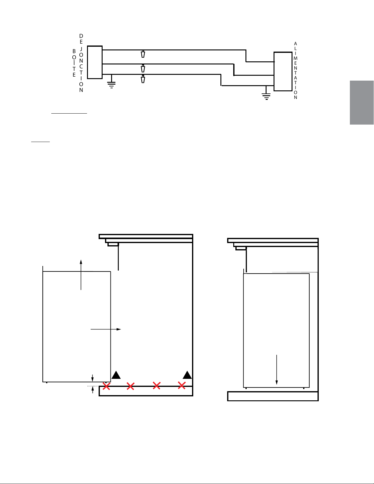
REMARQUE Laissez une longueur de fils suffisante pour que l’appareil puisse être retiré de
l’enceinte sans le débrancher du circuit d’alimentation.
NOIR
BLANC
NOIR
BLANC
ALIMENTATION
DE
JONCTION
BOÎTE
VERT
VERT
TERRE
NOIR
NOIR
NOIR
BLANC
BLANC
INTERRUPTEUR
MURAL
ALIMENTATION
CAPUCHONS DE
CONNEXION
MARRET
ROUGE
ROUGE
VERT
VERT
THERMOSTAT
ROUGE
ROUGE
(L1)
(N)
(G)
CAPUCHONS DE
CONNEXION
(L1)
(N)
(L1)
(N)
DE
JONCTION
BOÎTE
DE
JONCTION
BOÎTE
Fig. 1
Fig. 2
3.3.2 INSTALLATION DE L'APPAREIL
A.
Ont à deux personnes de soulever l’appareil et insérez dans l’ouverture, en laissant un espace de 3/8"
(9.5mm) entre l’appareil et la base du plancher. Ne faites pas glissez l’appareil, plancher ou d’autres
surfaces peintes peuvent rayer, voir Figure 1.
B. Placez l’appareil vers le bas sur la plancher en place., voir Figure 2.
C. Si l'appareil ne siègent pas à plat sur le sol ou tablette, appliquer une cale (non fourni) sous les patins
en nylon et ajuster jusqu'à ce niveau.
MANTEL
TABLETTE
APPLIANCE
APPAREIL
1/4"
MANTEL
TABLETTE
APPLIANCE
APPAREIL
STEP 1: LIFT
ÉTAPES 1: SOULEVER
STEP 2: INSERT
ÉTAPES 2: INSÉREZ
STEP 3: SET APPLIANCE
ÉTAPES 3: RÉGLÉ APPAREIL
DO NOT SLIDE APPLIANCE
NE GLISSEZ PAS L'APPAREIL
!
!
MANTEL
TABLETTE
APPLIANCE
APPAREIL
1/4"
MANTEL
TABLETTE
APPLIANCE
APPAREIL
STEP 1: LIFT
ÉTAPES 1: SOULEVER
STEP 2: INSERT
ÉTAPES 2: INSÉREZ
STEP 3: SET APPLIANCE
ÉTAPES 3: RÉGLÉ APPAREIL
DO NOT SLIDE APPLIANCE
NE GLISSEZ PAS L'APPAREIL
!
!
TABLETTE TABLETTE
NOTE: Cet appareil est équipé de patins en nylon situés sur les quatre coins inférieurs. Pour éviter
d'endommager la base de la tablette, soulevez délicatement l'appareil dans la tablette tout en évitant
le contact avec le bord avant de la base du tablette.
FR
W415-1662 / 05.17.16
38
4.0 INSTRUCTIONS DE FONCTIONNEMENT
L'appareil est prêt à fonctionner dès qu'il est correctement branché dans une prise de courant mise à la terre
(120V).
ATTENTION: Assurez-vous que les disjoncteurs de la maison pour ce circuit soient allumés. Lorsque vous
branchez d’abord l’appareil à une source d’ alimentation de l’unité effectuera une DEL vérifier. L'appareil se
Le panneau de côntrolé est situé dans la partie supérieure avant de l'appareil, comme illustrée.
4.1 INTERRUPTEUR ET PANNEAU DE COMMANDE
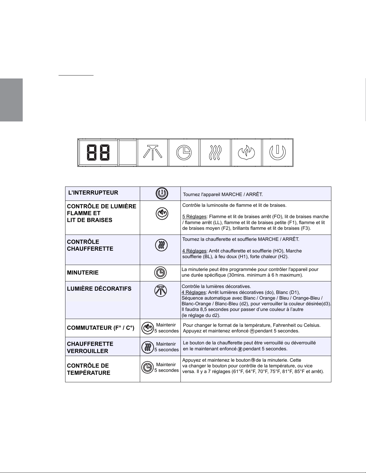
L’INTERRUPTEUR
Tournez l'appareil MARCHE / ARRÊT.
CONTRÔLE DE LUMIÈRE
FLAMME ET
LIT DE BRAISES
CONTRÔLE
CHAUFFERETTE
LUMIÈRE DÉCORATIFS
(SEULMENT CEFB29H)
MINUTERIE
CONTRÔLE DE
TEMPÉRATURE
Contrôle la luminosite de flamme et lit de braises.
5 Réglages
: Flamme et lit de braises arrêt (FO), lit de braises marche
/ flamme arrêt (LL), flamme et lit de braises petite (F1), flamme et lit
de braises moyen (F2), brillants flamme et lit de braises (F3).
Tournez la chaufferette et soufflerie MARCHE / ARRÊT.
4
Réglages: Arrêt chaufferette et soufflerie
(HO), Marche
soufflerie (BL), à feu doux (H1), forte chaleur (H2).
Contrôle la lumières décoratives.
4
Réglages: Arrêt lumières décoratives (do), Blanc (D1),
Séquence automatique avec Blanc / Orange / Bleu / Orange-Bleu /
Blanc-Orange / Blanc-Bleu (d2), pour verrouiller la couleur désirée(d3).
Il faudra 8,5 secondes pour passer d’une couleur à l’autre
(le réglage du d2).
La minuterie peut être programmée pour contrôler l'appareil pour
une durée spécifique (30mins. minimum à 6 h maximum).
Appuyez et maintenez le bouton de la minuterie. Cette
va changer le bouton pour contrôle de la température, ou vice
versa. Il y a 7 réglages (61°F, 64°F, 70°F, 75°F, 81°F, 85°F et arrêt).
COMMUTATEUR (F° / C°)
Maintenir
5 secondes
Pour changer le format de la température, Fahrenheit ou Celsius.
Appuyez et maintenez enfoncé pendant 5 secondes.
CHAUFFERETTE
VERROUILLER
Maintenir
5 secondes
Le bouton de la chaufferette peut être verrouillé ou déverrouillé
en le maintenant enfoncé pendant 5 secondes.
Maintenir
5 secondes
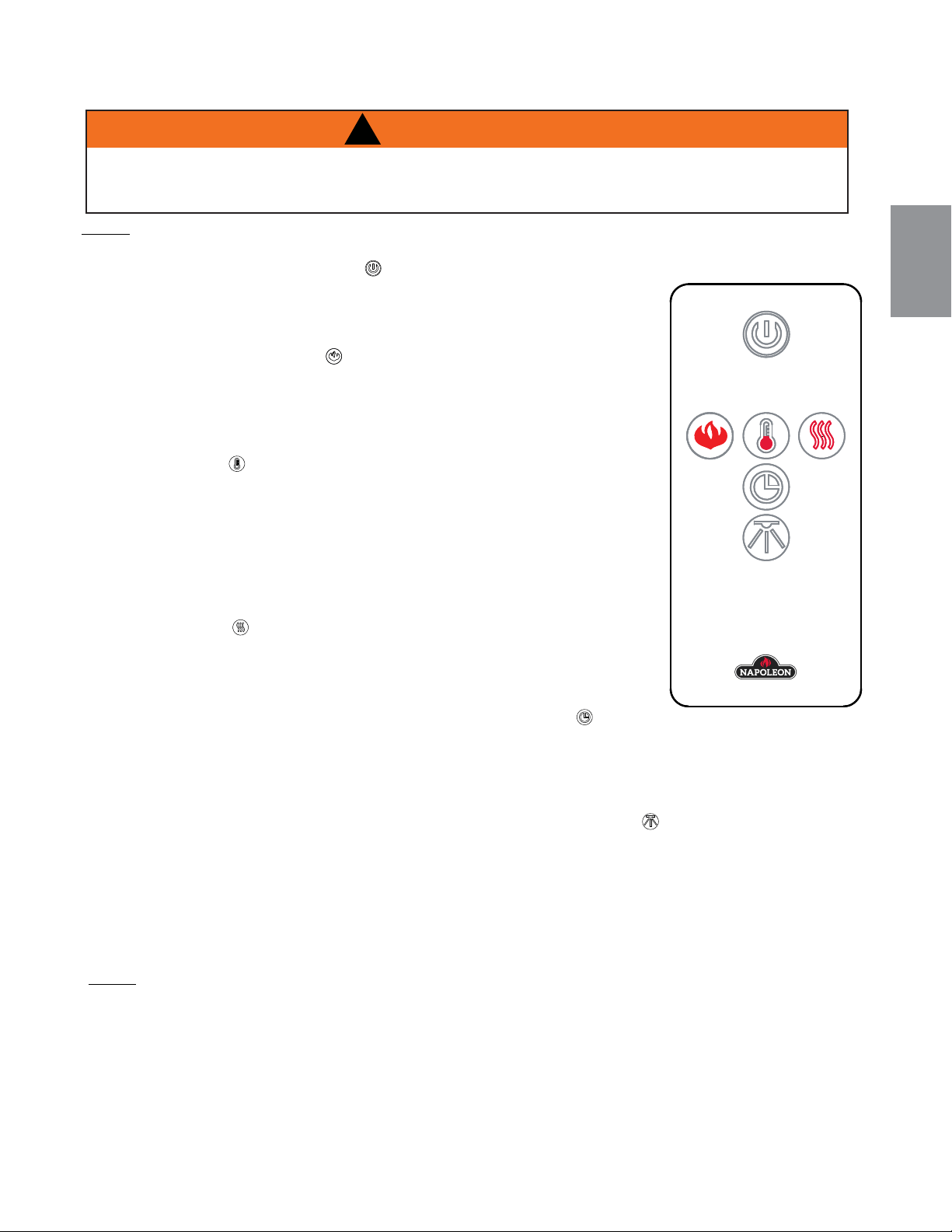
FR
W415-1662 / 05.17.16
39
4.2 UTILISATION DE LA TÉLÉCOMMANDE
!
WARNING
A. Le bouton d’alimentation peut servir à allumer ou éteindre l’appareil.
Le fait d’appuyer sur ce bouton met l’appareil sous tension. Le fait
d’appuyer sur ce bouton encore, s'éteint le l'appareil. La braise et le
bûches va s'estomper au bout de 4 secondes.
B. Pour régler la hauteur de flamme la luminosité et lit de braises, appuyez
sur le bouton de flammes . Il ya un lit de braise et de la lumière trois
niveaux de luminosité sont offerts ainsi qu’un réglage d’arrêt (LL, F1, F2,
F3 et F0). F3 est à l’intensité la plus élevée et LL est à seulement lit de
braises.
C. Pour utiliser la fonction thermostat, appuyez sur le bouton de
thermostat, Il y a 7 réglages (61°F, 64°F, 70°F, 75°F, 81°F, 85°F
et off). Par défaut, la température s’affiche en Fahrenheit. Enfoncez
la fonction thermostat pour faire défiler les différents réglages. Pour
accéder au format de température désiré, maintenez enfoncé le bouton
de thermostat. L’affichage basculera de Celsius à Fahrenheit, ou
inversement. Lorsque la température ambiante est deux degré inférieur
à la température réglée, la chaufferette se met en marche.
D. Pour actionner la chaufferette et soufflerie, appuyez sur le bouton
chaufferette Enfoncez le bouton chaufferette encore pour pour régler
la température de la chaleur basse ou haute souhaitée; enfoncez le
bouton chaufferette encore pour éteindre la chaufferette.
E. La minuterie contrôle tous les modes de fonctionnement de l'appareil.
Pour activer la minuterie, appuyez sur le bouton de minuterie ,
L'icône s’illuminera et l’heure s’affichera sur l'écran à DEL. Pour choisir
l’heure désirée, appuyez sur le bouton de minuterie. Il y a 8 réglages (30 mins.,1h, 2h, 3h, 4h, 5h, 6h
et off) qui s’afficheront sur l’écran à DEL, chacun représentant la durée de fonctionnement. Le foyer
s’éteint à l’heure réglée.
F. Pour activer la lumière de décoration, appuyez sur le bouton de lumière .Trois niveaux sont offerts
pour faire défiler les différents ainsi qu’un réglage d’arrêt (d1, d2, d3 et d0). d1 blanc, d2 changement
de couleur, du blanc au orange, au bleu et au orange et bleu, et au blanc-orange et blanc et bleu et d3
pour verrouiller la couleur désirée. Il faudra 8,5 secondes pour passer d’une couleur à l’autre lorsque
le réglage d2 est sélectionné.
G. Pour éteindre l'appareil, appuyez une fois sur le bouton d’alimentation sur le télécommande, ou
placez l’interrupteur principal en position d’arrêt sur le panneau de contrôle de l’appareil.
NOTE: Pour que la télécommande fonctionne bien, elle doit toujours être à moins de 8 mètres ou 26
pieds de l’appareil.
NOTE: Lors de l’utilisation de la télécommande, vous devez la pointer vers le centre sur le devant de l’appareil.
!
AVERTISSEMENT
COUPEZ L’ALIMENTATION ÉLECTRIQUE À L’APPAREIL ET LAISSEZ-LE REFROIDIR AVANT
D’EFFECTUER UN ENTRETIEN. SEUL UN TECHNICIEN DE SERVICE QUALIFIÉ PEUT EFFECTUER
L’ENTRETIEN OU LA RÉPARATION DE CET APPAREIL ÉLECTRIQUE.
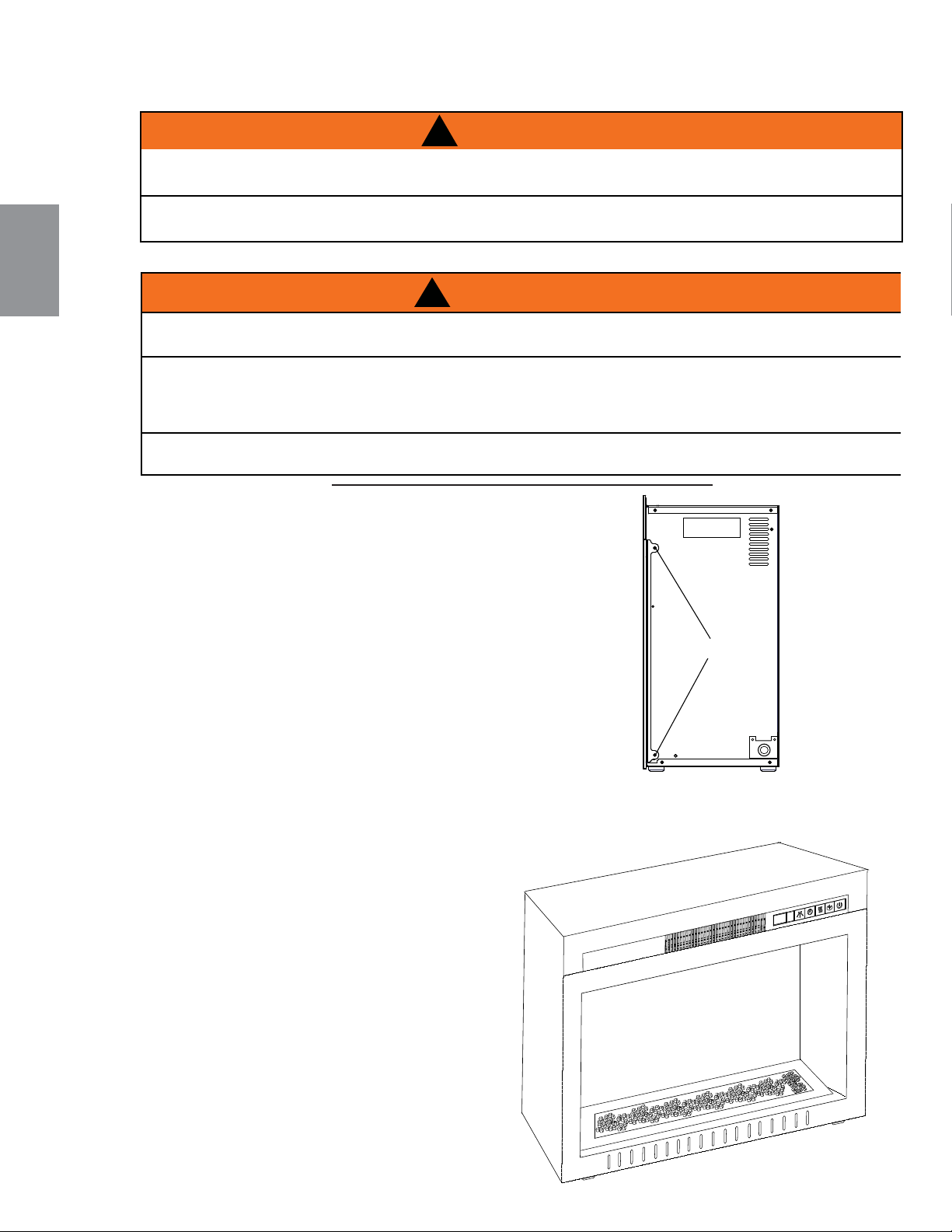
FR
W415-1662 / 05.17.16
40
5.0 FINITIONS
5.1 ENLÈVEMENT ET INSTALLATION DE LA PORTE VITRÉE
A. Retirez les 4 vis à partir de l'appareil, comme illustreé.
B. Retirez la porte vitrée et placez sur une surface douce
non abrasive.
C. Inversez ces étapes pour réinstaller la porte vitrée..
!
AVERTISSEMENT
!
AVERTISSEMENT
!
LE RACCORDEMENT PAR CÂBLE DOIT ÊTRE COMPLÉTÉ AVANT LA FINITION AFIN D'ÉVITER
TOUTE RECONSTRUCTION.
LES ENTRÉES D'AIR ET LES SORTIES D'AIR DE L'APPAREIL NE DOIVENT JAMAIS ÊTRE
COUVERTES.
!
AVERTISSEMENT
LA VITRE PEUT ÊTRE CHAUDE, NE TOUCHEZ PAS LA VITRE JUSQU’À CE QU’ELLE AIT REFROIDI.
LES LOQUETS DE PORTE FONT PARTIE D'UN DISPOSITIF DE SÉCURITÉ ET DOIVENT ÊTRE ADÉQUATEMENT
VERROUILLÉS. NE FAITES PAS FONCTIONNER L’APPAREIL LORSQUE LES LOQUETS SONT DÉVERROUILLÉS.
LES MATÉRIAUX DE FAÇADE ET DE FINITION NE DOIVENT PAS NUIRE À LA CIRCULATION DE L'AIR DANS LES
OUVERTURES D'AIR ET LES PERSIENNES, NI AU FONCTIONNEMENT DES PERSIENNES OU DES PORTES. ILS
NE DOIVENT PAS NON PLUS ENTRAVER L'ACCÈS POUR L'ENTRETIEN. RESPECTEZ TOUS LES DÉGAGEMENTS
AUX MATÉRIAUX COMBUSTIBLES.
AVANT D’ENLEVER LA PORTE, ÉTEIGNEZ L’APPAREIL ET ATTENDEZ QUE CE DERNIER SOIT FROID AU
TOUCHER. LES PORTES SONT LOURDES ET FRAGILES; MANIPULEZ AVEC SOIN.
75.1
!
AVERTISSEMENT
LES LOQUETS DE PORTE FONT PARTIE D'UN DISPOSITIF DE SÉCURITÉ ET DOIVENT ÊTRE ADÉQUATEMENT
VERROUILLÉS. NE FAITES PAS FONCTIONNER L’APPAREIL LORSQUE LES LOQUETS SONT DÉVERROUILLÉS.
LES MATÉRIAUX DE FAÇADE ET DE FINITION NE DOIVENT PAS NUIRE À LA CIRCULATION DE L'AIR DANS LES
OUVERTURES D'AIR ET LES PERSIENNES, NI AU FONCTIONNEMENT DES PERSIENNES OU DES PORTES. ILS
NE DOIVENT PAS NON PLUS ENTRAVER L'ACCÈS POUR L'ENTRETIEN. RESPECTEZ TOUS LES DÉGAGEMENTS
AUX MATÉRIAUX COMBUSTIBLES.
AVANT D’ENLEVER LA PORTE, ÉTEIGNEZ L’APPAREIL ET ATTENDEZ QUE CE DERNIER SOIT FROID AU
TOUCHER. LES PORTES SONT LOURDES ET FRAGILES; MANIPULEZ AVEC SOIN.
75.1
THIS WARNING FOR ELECTRICS ONLY:
SCREW
VIS
5.2 PLACER LA BRAISES VITRIFIÉES
A. Enlevez la porte vitrée, voir la section «
ENLÈVEMENT ET INSTALLATION DE LA
PORTE VITRÉE ».
B. Saupoudrer la braises vitrifiées uniformément
sur le plateau de PVC. Assurer vitrifiées reste
dans la cavité de la plateau.
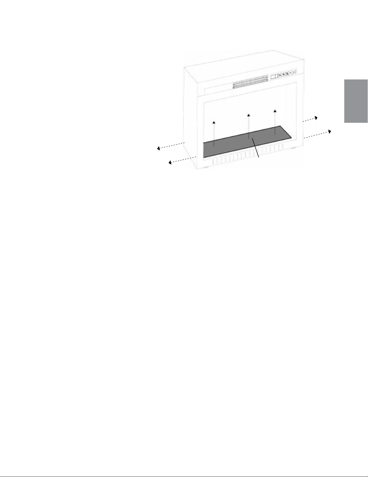
FR
W415-1662 / 05.17.16
41
VIS
LIT DE
BRAISES
* NEFB27HG ILLUSTRÉ
A. Retirez les braises vitrifiées du plateau
du lit de braises.
B. Retirez les 4 vis, comme illustré.
C. Soulevez le lit de braises à partir de
l'appareil et enlever.
VIS
5.3 RETRAIT DE L'ENSEMBLE DE LA GRILLE DU LIT DE BRAISES
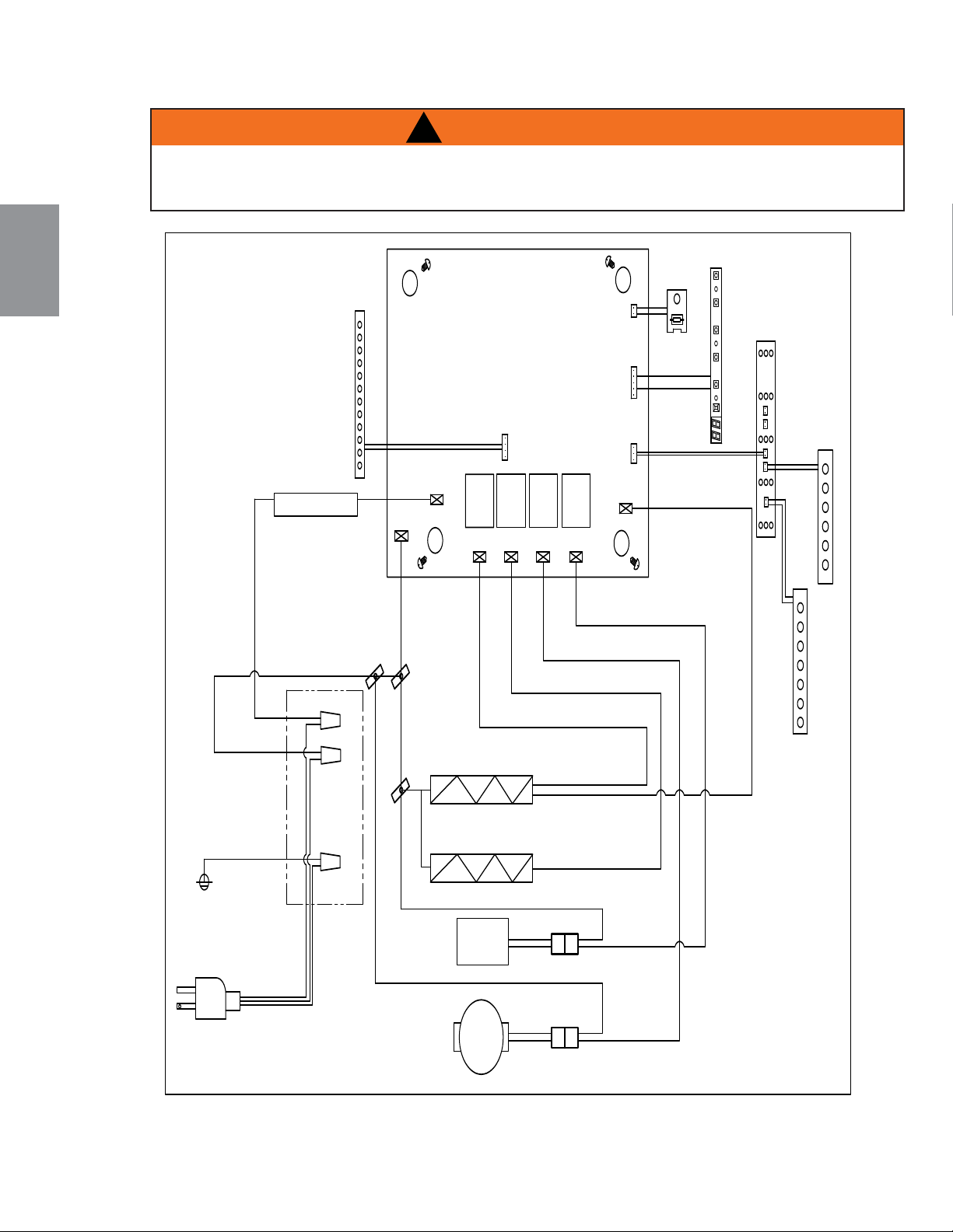
FR
W415-1662 / 05.17.16
42
6.0 SCHÉMA DE CÂBLAGE
!
AVERTISSEMENT
COUPEZ L’ALIMENTATION ÉLECTRIQUE À L’APPAREIL ET LAISSEZ-LE REFROIDIR AVANT
D’EFFECTUER UN ENTRETIEN. SEUL UN TECHNICIEN DE SERVICE QUALIFIÉ PEUT EFFECTUER
L’ENTRETIEN OU LA RÉPARATION DE CET APPAREIL ÉLECTRIQUE.
TITLE: LABEL, WIRE DIAGRAM (NEFB24/27/29HG) PART #: W385-2157
REVISION:
DATE: 04.27.16_H.W.
MATERIAL: CLASS IIA-1 PERMANENT LEXAN ADHESIVE LABEL, MINIMUM THICKNESS 0.1MM,
TEMPERATURE RATING MINIMUM OF 121°C (250°F)
SPECIFICATION: BLACK LETTERING ON SILVER BACKGROUND
LABEL SIZE: 5 7/8" (150mm) x 4 3/8" (111mm)
PLUG /
FICHE
FAN /
SOUFFLERIE
MOTOR /
MOTEUR
AC-N
AC-L
RLY1 RLY2 RLY3 RLY4
NTC
OUTOUT
OUT
IN
#7
#8
#5
#6
#2 #4
#14
#1
#9
#3
#11
#12
#13
#10
#15
CARTE DE CIRCUIT IMPRIMÉ
MAIN PCB BOARD /
DECORATION /
DÉCORATION
L
N
G
WIRE NUT /
CONNECTEUR
DE FILS
WIRE NUT /
CONNECTEUR
DE FILS
WIRE NUT /
CONNECTEUR
DE FILS
HEATER 700W2 /
CHAUFFERETTE 700W2
HEATER 700W1 /
CHAUFFERETTE 700W1
THERMAL CUT-OFF /
COUPURE
THERMIQUE
DECORATION LIGHT (OPTIONAL) /
DECORATION DE LUMIÈRE(OPTIONNEL)
700W1
700W2
MOTOR /
MOTEUR
FAN /
SOUFFLERIE
T-FUSE /
FUSIBLE
FLAME /
FLAMME
DISPLAY CN3 /
AFFICHAGE
TEMPERATURE
SENSOR /
CAPTEUR DE
EMPÉRATURE
CONTROL PANEL BOARD /
PANNEAU DE CONTRÔLÉ
FLAME LED LIGHT /
LUMIÈRE DEL DE FLAMME
#1 EMBER BED LED /
LIT DE BRAISES DE DEL #1
W385-2157
#2 EMBER BED LED /
LIT DE BRAISES DE DEL #2
FR
W415-1662 / 05.17.16
43
7.0 RECHANGES
Contactez votre détaillant ou le fabricant pour les questions concernant les prix et la disponibilité des pièces
de rechange. Normalement, toutes les pièces peuvent être commandées chez votre détaillant autorisé.
POUR UN REMPLACEMENT DE PIÈCE SOUS GARANTIE, UNE PHOTOCOPIE DE LA FACTURE ORIGI-
NALE SERA REQUISE AFIN DE POUVOIR HONORER LA DEMANDE.
Lorsque vous commandez des pièces, donnez toujours
l’information suivante :
● Modèle et numéro de série de l’appareil
● Date d’installation de l’appareil
● Numéro de la pièce
● Description de la pièce
● Fini
POUR PLUS D’INFORMATION, CONTACTEZ VOTRE
DÉTAILLANT AUTORISÉ.
!
AVERTISSEMENT
!
AVERTISSEMENT
!
OMETTRE DE POSITIONNER LES PIÈCES
CONFORMÉMENT AUX INSTRUCTIONS DU
MANUAL OU D’UTILISER UNIQUEMENT DES
PIÈCES SPÉCIFIQUEMENT APPROUVÉES POUR
CET APPAREIL PEUT CAUSER DES DOMMAGES
MATÉRIELS OU DES BLESSURES CORPORELLES.
41.1
Pour le service après-vente, veuillez composer le 1-866-820-8686
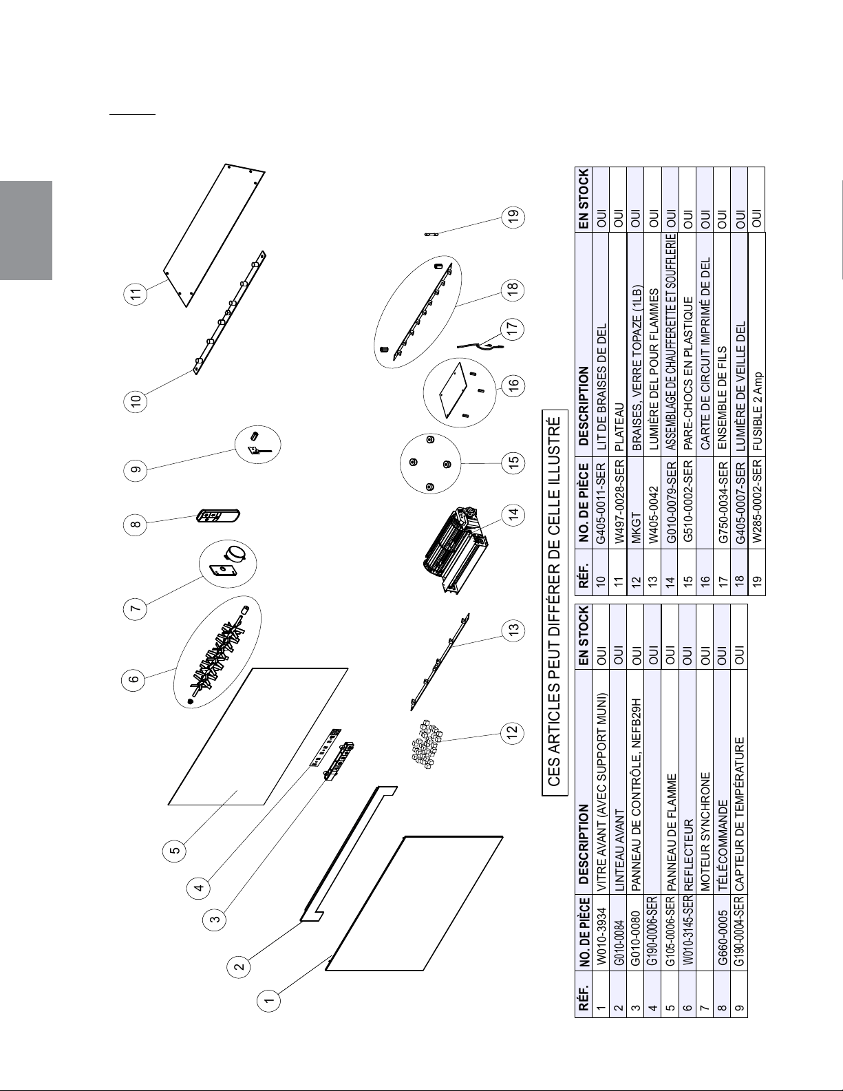
FR
W415-1662 / 05.17.16
44
NOTE: Usez de prudence lorsque vous enlevez et jetez des débris de verre ou des composants
endommagés. Assurez-vous d’aspirer tous les débris de verre à l’intérieur de l'appareil avant de le
faire fonctionner.
7.1 VUE D'ENSEMBLE NEFB24HG
RÉF.
NO. DE PIÈCE
DESCRIPTION
1
2
3
4
5
6
7
8
RÉF.
NO. DE PIÈCE
DESCRIPTION
11
CES ARTICLES PEUT DIFFÉRER DE CELLE ILLUSTRÉ
G010-0079-SER
W405-0042
W010-3934
G660-0005
W010-3145-SER
REFLECTEUR
W435-0059-SER
W190-0066-SER
CARTE DE CIRCUIT IMPRIMÉ DE DEL
31
14
15
12
13
G010-0080
32
33
34
35
3
6
3
7
8
9
10
13
14
2217
G750-0034-SER
10
G405-0011-SER
9
G190-0004-SER
16
G405-0007-SER
LUMIÈRE DE VEILLE DEL
18
17
18
W497-0028-SER
PLATEAU
MKGT
12
G190-0006-SER
G510-0002-SER
PARE-CHOCS EN PLASTIQUE
3
15
3
16
19
W285-0002-SER
FUSIBLE 2 Amp
11
19
EN STOCK
EN STOCK
VITRE AVANT (AVEC SUPPORT MUNI)
G010-0084
LINTEAU AVANT
PANNEAU DE CONTRÔLE, NEFB29H
BORD DE PANNEAU DE CONTRÔLE
G105-0006-SER
PANNEAU DE FLAMME
MOTEUR SYNCHRONE
TÉLÉCOMMANDE
CAPTEUR DE TEMPÉRATURE
LIT DE BRAISES DE DEL
BRAISES, VERRE TOPAZE (1LB)
LUMIÈRE DEL POUR FLAMMES
ASSEMBLAGE DE CHAUFFERETTE ET SOUFFLERIE
ENSEMBLE DE FILS
OUI
OUI
OUI
OUI
OUI
OUI
OUI
OUI
OUI
OUI
OUI
OUI
OUI
OUI
OUI
OUI
OUI
OUI
OUI
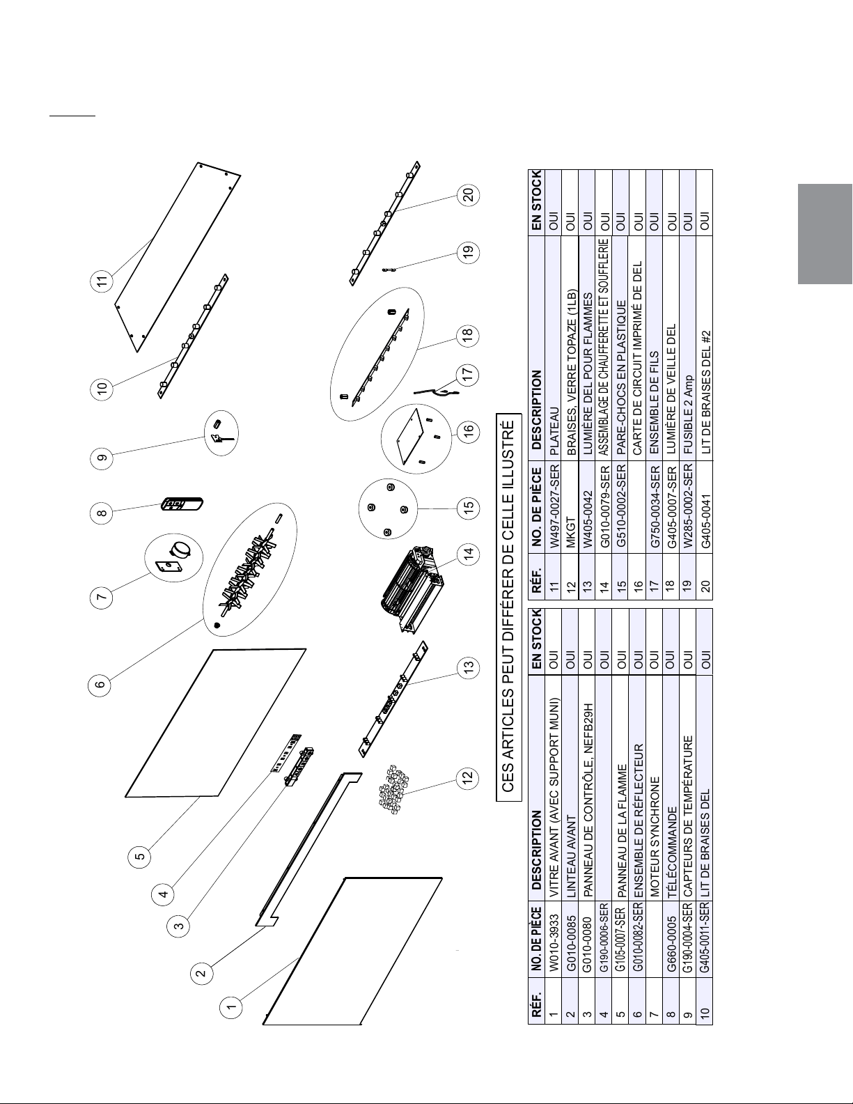
FR
W415-1662 / 05.17.16
45
NOTE: Usez de prudence lorsque vous enlevez et jetez des débris de verre ou des composants
endommagés. Assurez-vous d’aspirer tous les débris de verre à l’intérieur de l'appareil avant de le
faire fonctionner.
7.2 VUE D'ENSEMBLE NEFB27HG
RÉF.
NO. DE PIÈCE
DESCRIPTION
1
2
3
4
5
6
7
8
RÉF.
NO. DE PIÈCE
DESCRIPTION
11
CES ARTICLES PEUT DIFFÉRER DE CELLE ILLUSTRÉ
G105-0007-SER
G010-0079-SER
W405-0042
G010-0085
W010-3933
G660-0005
G010-0082-SER
ENSEMBLE DE RÉFLECTEUR
W435-0059-SER
W190-0066-SER
31
14
15
12
13
G010-0080
3
2
33
34
35
3
6
3
7
8
9
10
13
14
2217
G750-0034-SER
9
G190-0004-SER
16
G405-0007-SER
18
17
18
W497-0027-SER
PLATEAU
MKGT
12
G190-0006-SER
G510-0002-SER
PARE-CHOCS EN PLASTIQUE
3
15
3
16
19
W285-0002-SER
11
19
EN STOCK
EN STOCK
VITRE AVANT (AVEC SUPPORT MUNI)
LINTEAU AVANT
PANNEAU DE CONTRÔLE, NEFB29H
BORD DE PANNEAU DE CONTRÔLE
PANNEAU DE LA FLAMME
MOTEUR SYNCHRONE
TÉLÉCOMMANDE
CAPTEURS DE TEMPÉRATURE
BRAISES, VERRE TOPAZE (1LB)
ASSEMBLAGE DE CHAUFFERETTE ET SOUFFLERIE
LUMIÈRE DEL POUR FLAMMES
CARTE DE CIRCUIT IMPRIMÉ DE DEL
ENSEMBLE DE FILS
LUMIÈRE DE VEILLE DEL
FUSIBLE 2 Amp
20
10
G405-0011-SER
LIT DE BRAISES DEL
20
G405-0041
LIT DE BRAISES DEL #2
OUI
OUI
OUI
OUI
OUI
OUI
OUI
OUI
OUI
OUI
OUI
OUI
OUI
OUI
OUI
OUI
OUI
OUI
OUI
OUI
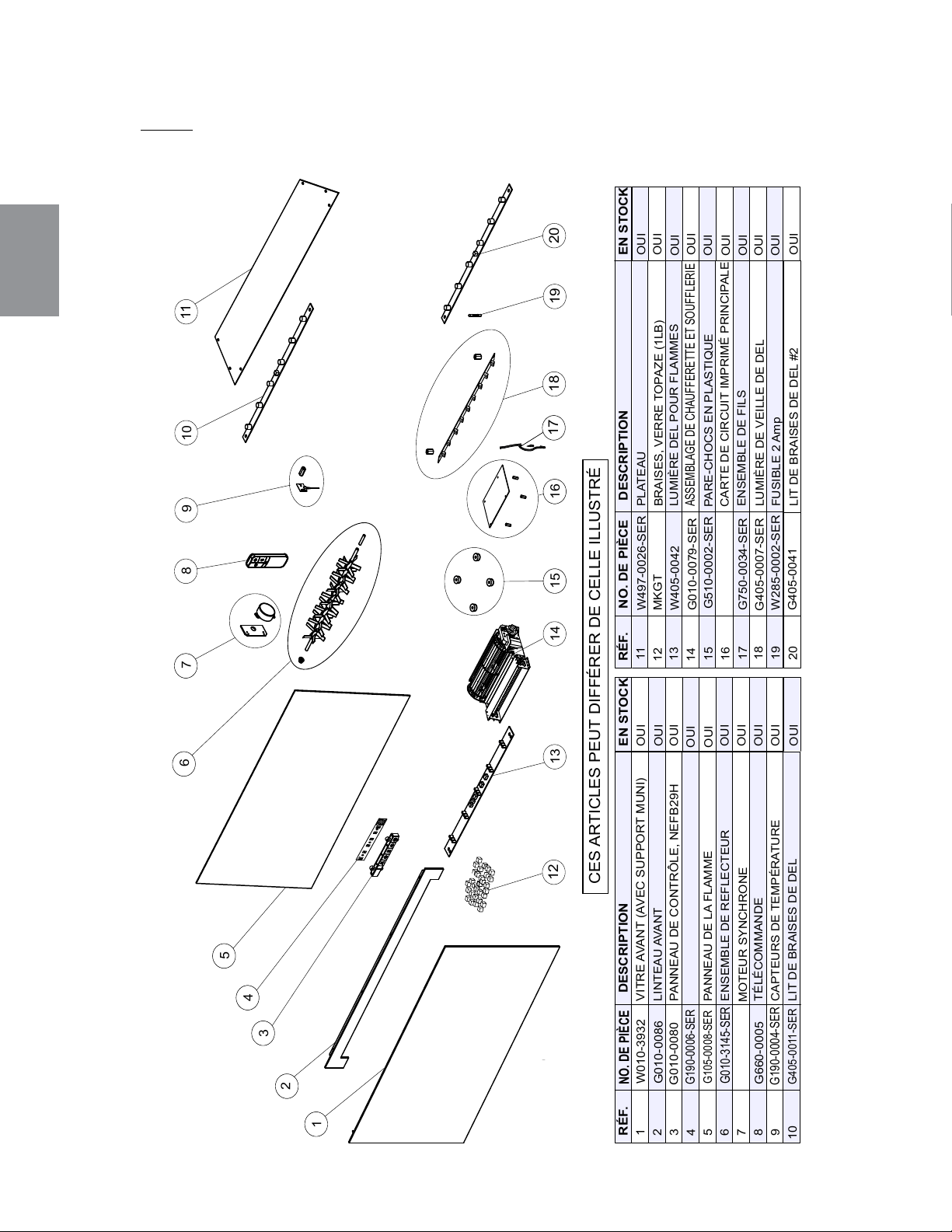
FR
W415-1662 / 05.17.16
46
NOTE: Usez de prudence lorsque vous enlevez et jetez des débris de verre ou des composants
endommagés. Assurez-vous d’aspirer tous les débris de verre à l’intérieur de l'appareil avant de le
faire fonctionner.
7.3 VUE D'ENSEMBLE NEFB29HG
RÉF.
NO. DE PIÈCE
DESCRIPTION
1
2
3
4
5
6
7
8
RÉF.
NO. DE PIÈCE
DESCRIPTION
11
CES ARTICLES PEUT DIFFÉRER DE CELLE ILLUSTRÉ
G105-0008-SER
G010-0079-SER
W405-0042
G010-0086
W010-3932
G660-0005
G010-3145-SER
W435-0059-SER
W190-0066-SER
31
14
15
12
13
G010-0080
3
2
33
34
35
3
6
3
7
8
9
10
13
14
2217
G750-0034-SER
10
G405-0011-SER
9
G190-0004-SER
16
G405-0007-SER
18
17
18
W497-0026-SER
PLATEAU
MKGT
12
G190-0006-SER
G510-0002-SER
PARE-CHOCS EN PLASTIQUE
3
15
3
16
19
W285-0002-SER
FUSIBLE 2 Amp
11
19
EN STOCK
EN STOCK
20
20
G405-0041
VITRE AVANT (AVEC SUPPORT MUNI)
LINTEAU AVANT
PANNEAU DE CONTRÔLE, NEFB29H
BORD DE PANNEAU DE CONTRÔLE
PANNEAU DE LA FLAMME
ENSEMBLE DE REFLECTEUR
MOTEUR SYNCHRONE
TÉLÉCOMMANDE
CAPTEURS DE TEMPÉRATURE
LIT DE BRAISES DE DEL
BRAISES, VERRE TOPAZE (1LB)
LUMIÈRE DEL POUR FLAMMES
ASSEMBLAGE DE CHAUFFERETTE ET SOUFFLERIE
CARTE DE CIRCUIT IMPRIMÉ PRINCIPALE
ENSEMBLE DE FILS
LUMIÈRE DE VEILLE DE DEL
LIT DE BRAISES DE DEL #2
OUI
OUI
OUI
OUI
OUI
OUI
OUI
OUI
OUI
OUI
OUI
OUI
OUI
OUI
OUI
OUI
OUI
OUI
OUI
OUI
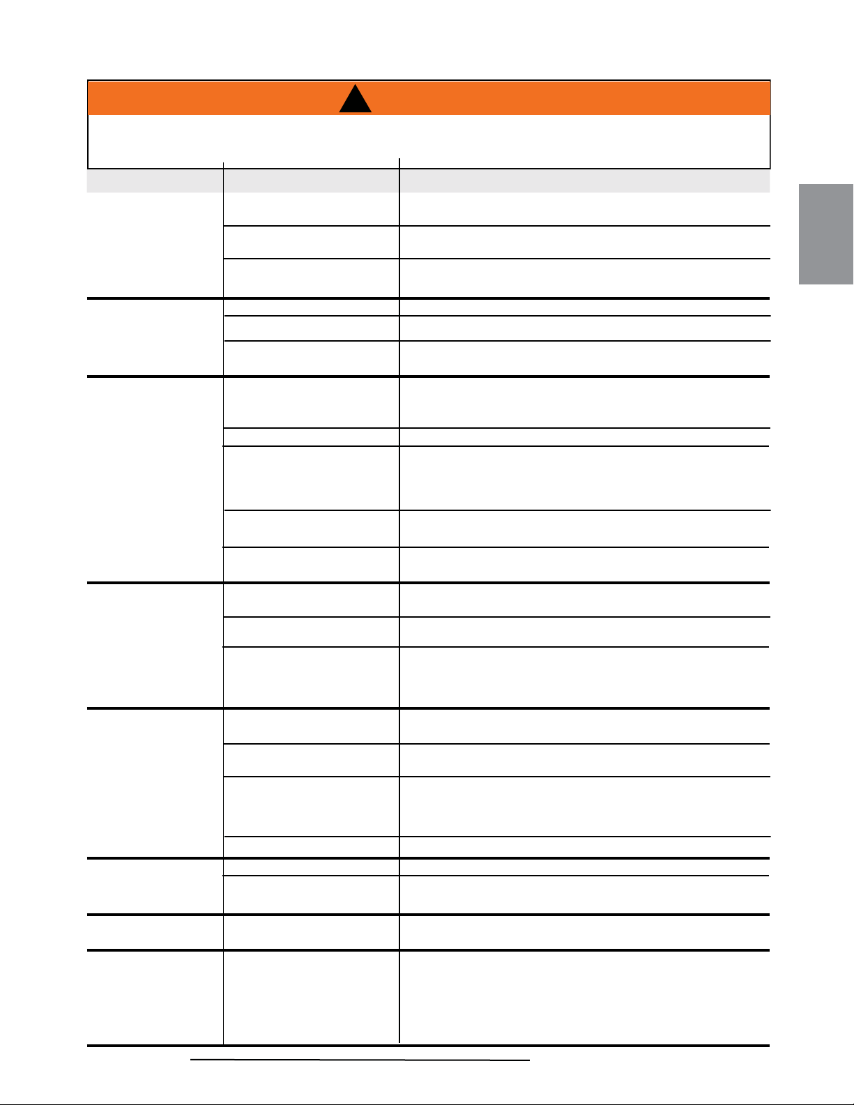
FR
W415-1662 / 05.17.16
47
8.0 GUIDE DE DÉPANNAGE
COUPEZ L’ALIMENTATION ÉLECTRIQUE À L’APPAREIL ET LAISSEZ-LE REFROIDIR AVANT
D’EFFECTUER UN ENTRETIEN. SEUL UN TECHNICIEN DE SERVICE QUALIFIÉ PEUT
EFFECTUER L’ENTRETIEN OU LA RÉPARATION DE CET APPAREIL.
SYMPTÔME PROBLÈME SOLUTIONS
La luminosité du
jeu de fl ammes est
faible ou inexistante
Éclat de fl amme ne pas
sélectionné
Flamme DEL sont brûlées
Carte de circuit imprimé sont
brûlées
Voir la section « OPÉRATION ».
Vérifi ez les DEL à l’intérieur du cylindre de création du jeu de
fl ammes et remplacez-les au besoin
Inspect the Main PCB Board and replace if necessary..
Le lit de braises ne
s’illumine pas ou
ne diminue pas en
luminosité
Luminosité ne pas sélectionnée
Braise DEL sont brûlées
Carte de circuit imprimé sont
brûlées
Voir la section « OPÉRATION ».
Vérifi ez que les braises DEL et remplacez-les au besoin
Vérifi ez les carte de circuit imprimé et remplacez-les au besoin
L’appareil n’émet
aucune chaleur
Appareil de chauffage
ne défi nissant ne pas
selectionné
Chauffeurette a été verrouillé
La température ambiante est
plus élevée que le réglage
de l’appareil (si réglée au
température du chambre)
Chauffe a surchauffé
L’appareil de chauffage est
brûlé
Voir la section « OPÉRATION », appareil de chauffage
comprend des sélections multiples comme le ventilateur
seulement, aucune chaleur, 750W (faible chaleur), 1500W (vif).
Voir la section « OPÉRATION », chaufferette verrouillé.
Réglez l’appareil à une température plus élevée (MOYEN ou
ÉLEVÉ)
Débranchez l’appareil, laissez-le refroidir pendant 15 minutes,
puis rebranchez-le, puis brancher ou allumer le disjoncteur sur.
Inspecter l’appareil SOUFFLERIE de chauffage et remplacez-
les au besoin
L’appareil s’éteint et
ne se rallume pas
Le disjoncteur de
la maison s’est déclenché
Le fusible de l’appareil a
sauté
L’appareil a surchauffé et
le dispositif de sécurité a
entraîné le déclenchement de
l’interrupteur thermique
Réinitialisez le disjoncteur
Remplacez le fusible
Débranchez l’appareil, laissez-le refroidir pendant 15 minutes,
puis rebranchez-le
L’appareil
ne s’allume
pas lorsque
l’interrupteur est mis
à « ON »
L’appareil n’est pas branché
dans une prise de courant
Vérifi ez la fi che puis rebranchez-la
Branchement par cable sont
incorrectes.
L’appareil a surchauffé et
le dispositif de sécurité a
entraîné le déclenchement de
l’interrupteur thermique
La carte de circuit est brûlé
Voir la section « BRANCHEMENT PAR CABLE ».
Débranchez l’appareil, laissez-le refroidir pendant 15 minutes,
puis rebranchez-le
Inspecter la carte de circuit et remplacez-les au besoin
La télécommande
ne fonctionne pas
Les piles sont faibles
Dysfonctionnement du
récepteur à distance
Remplacez les piles AA de la télécommande
S’assurer que le récepteur à distance n’est pas bloqué.
Replacer le panneau.
Flamme ne bouge
pas
Moteur calé/ne fonctionne
pas correctement
Cycle de marche/arrêt. Si le problème persiste, consulter le
concessionnaire.
La chaufferette
s’éteint auto-
matiquement
La température ambiante est
trop élevée
L’appareil est équipé d’un thermostat intégré et s’éteindra
automatiquement lorsque la température programmée sera
atteinte. Il s’allumera automatiquement lorsque la température de
la pièce descendra en dessous de la température programmée.
La température programmée dépend des réglages sélectionnés
pour la chaufferette
!
AVERTISSEMENT
!
AVERTISSEMENT
!
42.37
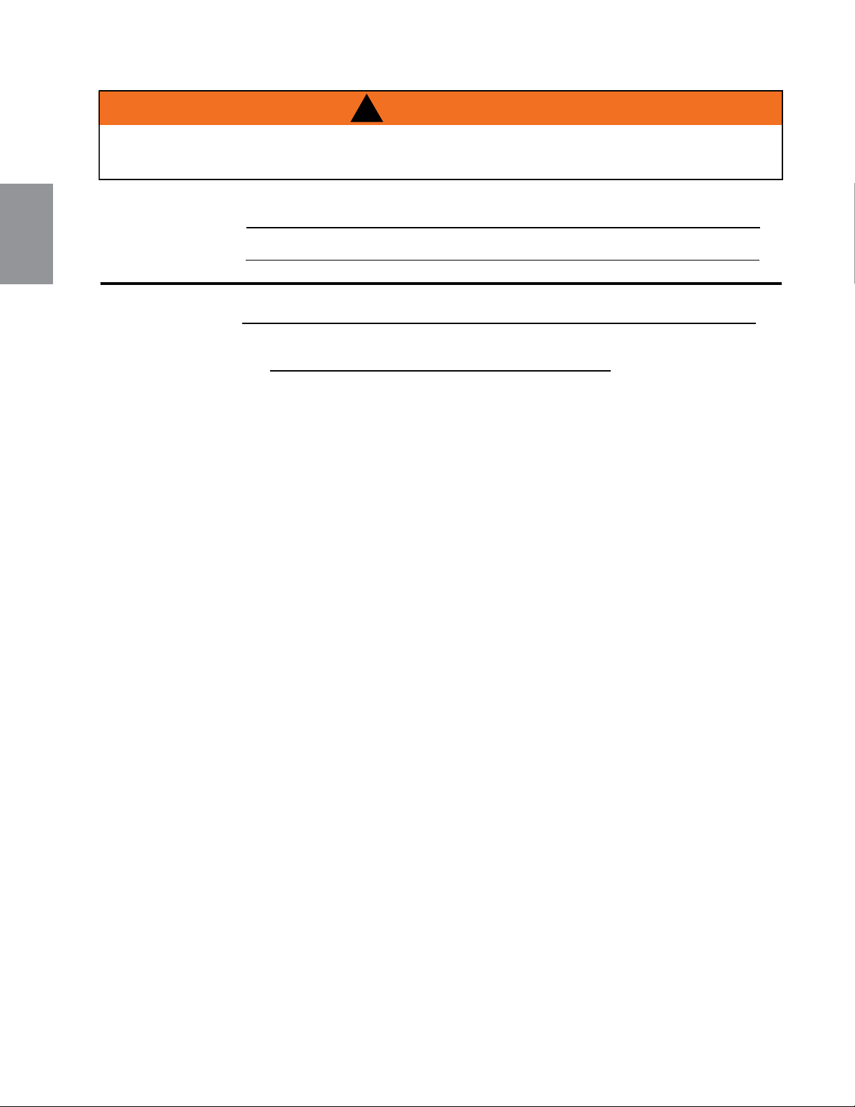
FR
W415-1662 / 05.17.16
48
!
AVERTISSEMENT
!
AVERTISSEMENT
!
COUPEZ L’ALIMENTATION ÉLECTRIQUE À L’APPAREIL ET LAISSEZ-LE REFROIDIR AVANT
D’EFFECTUER UN ENTRETIEN. SEUL UN TECHNICIEN DE SERVICE QUALIFIÉ PEUT
EFFECTUER L’ENTRETIEN OU LA RÉPARATION DE CET APPAREIL.
42.37
Fil thermostat non
connecté à PCB
Connecter le fi l.E1 Error Code
Connexion du thermostat
pcb est un court-circuit
Connexion du fi l à thermostat
PCB est lâche
Thermostat has failed Remplacez le thermostat.
Connecter le fi l fermement au
PCB.
E2 Error Code
Remplacez le thermostat.
Replacer PCB.
Thermostat est un court-
circuit.
FR
W415-1662 / 05.17.16
49
9.0 GARANTIE
NAPOLÉON garantit ses produits contre les défauts de fabrication à l’acheteur d’origine seulement. L’enregistrement de la garantie
n’est pas nécessaire. Fournissez simplement une preuve d’achat ainsi que le modèle et le numéro de série afi n d’effectuer une
réclamation de garantie. Napoléon® se réserve le droit de demander à son représentant d’inspecter tous produits ou pièces avant
d’honorer toute réclamation. L’achat doit avoir été fait par l’entremise d’un détaillant NAPOLÉON® autorisé et sous réserve des
conditions et limitations suivantes :
La couverture de la garantie débute à partir de la date d’installation originale.
Cette garantie du fabricant n’est pas transférable et ne peut être prolongée ou étendue par aucun de nos représentants quelle qu’en
soit la raison.
L’installation doit être faite conformément aux instructions d’installation incluses avec le produit et à tous les codes d’incendie et de
construction locaux et nationaux.
Cette garantie limitée ne couvre pas les dommages causés par un mauvais usage, un manque d’entretien, un accident, des altérations,
des abus ou de la négligence, et l’installation de pièces d’autres fabricants annulera cette garantie.
Cette garantie limitée ne couvre pas non plus les égratignures, les bossellements, la corrosion ou la décoloration causée par
une chaleur excessive, des produits d’entretien chimiques et abrasifs ou l’écaillage de pièces en porcelaine émaillée, le bris par
manipulation des bûches Phazer®.
Au cours de la première année seulement, cette garantie s’étend à la réparation ou au remplacement des pièces garanties dont les
matériaux ou la fabrication sont défectueux à la condition que le produit ait été utilisé conformément aux instructions de fonctionnement
et dans des conditions normales.
NAPOLÉON ne sera pas responsable de l’installation, de la main d’œuvre ou autres coûts ou dépenses relatives à la réinstallation
d’une pièce garantie, et de telles dépenses ne sont pas couvertes par cette garantie. Nonobstant toutes les dispositions contenues
dans cette garantie limitée, la responsabilité de NAPOLÉON sous cette garantie est défi nie comme ci-dessus et elle ne s’étendra à
aucun dommage accidentel, consécutif ou indirect.
Cette garantie défi nit l’obligation et la responsabilité de NAPOLÉON en ce qui concerne l’appareil électrique NAPOLÉON. Toute autre
garantie énoncée ou implicite en ce qui concerne ce produit, ses composants ou accessoires est exclue.
NAPOLÉON n’endosse, ni n’autorise aucun tiers à assumer en son nom, toutes autres responsabilités concernant la vente de ce
produit.
Tous dommages causés à l’appareil, aux garnitures en laiton ou autres composants par l’eau, les dommages causés par les
intempéries, de longues périodes d’humidité, la condensation, des produits chimiques ou produits d’entretien nuisibles ne seront pas la
responsabilité de NAPOLÉON.
La facture ou sa copie sera requise ainsi que le numéro de série et le numéro de modèle lors d’une réclamation auprès de votre
détaillant autorisé. La carte d’enregistrement de garantie doit être retournée dans les quatorze jours pour enregistrer la garantie.
NAPOLÉON® se réserve le droit de demander à son représentant d’inspecter tout produit ou pièce avant d’honorer toute réclamation.
Toutes les pièces remplacées en vertu de la politique de la garantie limitée ne peuvent faire l’objet que d’une seule réclamation.
Toutes les pièces remplacées au titre de la garantie seront couvertes pour une période de 90 jours à partir de leur date d’installation.
Le fabricant peut exiger que les pièces défectueuses ou les produits soient retournés ou que des photos numériques soient fournies pour valider la
réclamation. Les produits retournés doivent être expédiés port payé au fabricant pour une inspection en usine. Si un produit est déclaré défectueux,
le fabricant le réparera ou le remplacera.
Avant d’expédier votre appareil ou les pièces défectueuses, votre détaillant doit obtenir un numéro d’autorisation. Toute marchandise expédiée à
notre usine sans autorisation sera refusée et retournée à l’expéditeur.
Les coûts d’expédition ne sont pas couverts par cette garantie.
Des frais de service supplémentaires peuvent être appliqués si vous cherchez à obtenir des services au titre de la garantie auprès d’un détaillant.
2.5C
Les foyers électriques NAPOLÉON sont fabriqués conformément aux normes strictes du Certifi cat d’assurance de qualité
mondialement reconnu ISO 9001 : 2008.
Les produits NAPOLÉON sont conçus avec des composants et des matériaux de qualité supérieure, assemblés par
des artisans qualifi és qui sont fi ers de leur travail. Une fois assemblé, chaque foyer est soigneusement inspecté par un
technicien qualifi é avant d’être emballé pour garantir que vous, le client, recevez le produit de qualité dont vous vous
attendez de NAPOLÉON.
Les composants électriques et les pièces soumises à l’usure tels que le ventilateur/l’appareil de chauffage, les
moteurs, les interrupteurs, les roulements à billes en nylon et les télécommandes sont couverts et NAPOLÉON fournira
gratuitement les pièces de rechange durant la première année de la garantie limitée.
Les ampoules et les fusibles NE SONT PAS couverts par la garantie.
Les coûts de main-d’oeuvre relatifs aux réparations garanties ne sont pas couverts.
*La fabrication de chaque modèle varie. La garantie s’applique uniquement aux composants disponibles avec votre
appareil.
GARANTIE LIMITÉE DES APPAREILS ÉLECTRIQUES NAPOLÉON
CONDITIONS ET LIMITATIONS
TOUTES LES SPÉCIFICATIONS ET LES CONCEPTIONS SONT SUJETTES À MODIFICATIONS SANS PRÉAVIS EN RAISON DES
AMÉLIORATIONS CONSTANTES APPORTÉES AUX PRODUITS. NAPOLÉON EST UNE MARQUE DE COMMERCE DÉPOSÉE DE
WOLF STEEL LTÉE.
FR
W415-1662 / 05.17.16
50
Date
43.1
Problèmes particuliersTravail effectuéNom du technicienDétaillant
Historique d’entretien Wolf Steel
Cet appareil doit être entretenu annuellement selon son usage.
10.0 HISTORIQUE D'ENTRETIEN

FR
W415-1662 / 05.17.16
51
11.0 NOTES
44.1
Autres produits Napoléon
®
Foyers encastrés • Grils au charbon de bois • Foyers au gaz • Cascades d’eau
Poêles à bois • Produits HVAC • Foyers électriques • Foyers extérieurs • Grils à gaz de qualité
Foyers / Chauffage et Climatisation / Grils composez : 514-737-6294
napoleonproducts.com
7200, Route Transcanadienne, Montréal, Québec H4T 1A3
24 Napoleon Road, Barrie, Ontario, Canada L4M 0G8
214 Bayview Drive, Barrie, Ontario, Canada L4N 4Y8
103 Miller Drive, Crittenden, Kentucky, USA 41030