]
]
SEA/RS
[RR FTSM /:/NO
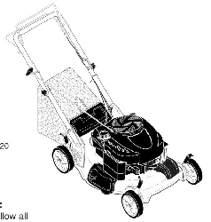
MODEL NUMBER 917.386240 OWNER'S MANUAL
• Assembly
o Operation
• Customer
Responsibilities
= Service
Adjustments
• Repair Parts
Caution:
Read and Follow
all Safety Rules
and Instructions
Before Operating
This Equipment
156695 8.29.96 VBL
SAFETY RULES
_Safe Operation Practices for Walk-Behind Mowers A
IMPORTANT: THIS CUTTING MACHINE IS CAPABLE OF AMPUTATING HANDS AND FEET AND THROWING OBJECTS,
FAILURE TO OBSERVE THE FOLLOWING SAFETY INSTRUCTIONS COULD RESULT 1N SERIOUS INJURY OR DEATH.
SAFETY STANDARDS REQUIRE OPERATOR PRESENCE CONTROLS TO MINIMIZE THE RISK OF INJURY. YOUR UNIT IS
EQUIPPED WITH SUCH CONTROLS. DO NOT ATTEMPT TO DEFEAT THE FUNCTION OF THE OPERATOR PRESENCE
CONTROLS UNDER ANY CIRCUMSTANCES.
TRAINING:
• Read this operator's manual carefully. Become familiar with
the controls and know how to operate your mower properly.
Learn how to quickly stop mower.
= Do not allow children to use your mower. Never allow adults
to use mower without proper instructions.
• Keep the area of operation clear of all persons, especially
small children and pets.
• use mower only as the manufacturer intended and as de-
scribed in this manual.
° Do not operate mower if it has been dropped or damaged in
any manner. Always have damage repaired before using
your mower.
• Do not use accessory attachments that are not recommended
by the manufacturer. Use of such attachments may be
hazardous.
• The blade turns when the engine is running.
PREPARATION:
* Always thoroughly check the area to be mowed and clear it of
all stones, sticks, wires, bones, and other foreign objects.
These objects wil! be thrown by the blade and can cause
severe injury.
° Always wear safety glasses or eye shields when starting and
while using your mower.
. Dress properly. Do not operate mower when barefoot or
wearing open sandals. Wear only solid shoes with good
traction when mowing.
, Check fuel tank before starting engine. Do not fill gas tank
indoors, when the engine is running or when the engine is hot.
Allow the engine to cool for several minutes before filling the
gas tank. Clean off any spilled gasoline before starting the
engine.
. Always make wheel height adjustments before starting your
mower. Never attempt to do this while the engine is running.
, Mow only in daylight or good artificial light.
OPERATION:
* Keep your eyes and mind on your mower and the area being
cut. Do not let other interests distract you.
. Do not mow wet or slippery grass. Never run while operating
your mower. Always be sure of your footing - keep a firm hold
on the handles and watk.
• Do not put hands or feet near or under rotating parts. Keep
clear of the discharge opening at all times.
o Always stop the engine whenever you leave or are not using
your mower, or before crossing driveways, walks, roads, and
any gravel-covered areas.
° Never direct discharge of material toward bystanders nor
allow anyone near the mower while you are operating it.
° Before cleaning, inspecting, or repairing your mower, stop the
engine and make absolutely sure the blade and all moving
parts have stopped, Then disconnect the spark pfug wire and
keep it away from the spark plug to prevent accidental
starting.
o
°
• Do not continue to run your mower if you hit a foreign object.
Foflow the procedure outlined above, then repair any dam-
age before restarting and operating you mower.
• Do not change the governor settings or overspeed the
engine. Engine damage or personal injury may result.
• Do not operate your mower if it vibrates abnormally. Exces-
sive vibration is an indication of damage; stop the engine,
safely check for the cause of vibration and repair as required.
Do not run the engine indoors. Exhaust fumes are danger*
OUS.
Never cut grass by pulling the mower towards you. Mow
across the face of slopes, never up and down or you might
lose your footing. Do not mow excessively steep slopes. Use
caution when operating the mower on uneven terrain or when
changing directions - maintain good footing.
Never operate your mower without proper guards, plates,
grass catcher or other safety devices in place.
MAINTENANCE AND STORAGE:
* Check the blade and the engine mounting bolts Often to be
sure they are tightened properly.
° Check all bolts, nuts and screws at frequent intervals for
proper tightness to be sure mower is in safe working condi-
tion.
o Keep all safety devices in place and working.
• To reduce fire hazard, keep the engine free of grass, leaves
or excessive grease and oil.
° Check gross catcher often for deterioration and wear and
replace worn bags. Use only replacement bags that are
recommended by and comply with specifications of the
manufacturer of your mower.
• Always keep a sharp blade on your mower.
• Allow engine to cool before stodng in any enclosure.
° Never store mower with fuel in the tank inside a building
where fumes may reach an open flame or an ignition source
such as a hot water heater, space heater, clothes dryer, etc.
A Look for this symbol t0' point out im--]
portant safety precautions. It means /
CAUTION!!! BECOMEALERT!It YOUR |
SAFETY IS INVOLVED. |
/
II1' i i,i
............... i i,j[ i i ii
CAUTION: Always disconnect spark
plug wire and place wire where it can-
not contact spark plug in order to pre-
vent accidental starting when setting
up, transporting, adjusting or making
repairs.
III1'1'111'11!1 I , i II
I I I IIII1'1'11! II IIII .....
A WARNING A
The engine exhaust from this product con-
tains chemicals known to the State of Califor-
nia to cause cancer, birth defects, or other
reproductive harm.
2
CONGRATULAT!ONS on your purchase of a Sears Lawn
Mower. It has been designed, engineered and manufac-
tured to give you the best possible dependability and
performance.
Should you experience any prob!em you cannot easily
remedy, ptease contact your nearest Sears Authorized
Service Center!Department. We have competent, well-
trained technicians and the proper tools to service or repair
this lawn mower.
Please read and retain this manual. The instructions will
enable you to assemble and maintain your lawn mower
properly. Always observe the "SAFETY RULES".
MODEL
NUMBER 917.386240
SERIAL
NUMBER
DATEOFPURCHASE
THE MODELAND SERIAL NUMBERS WILL BE FOUND
ON A DECAL ATTACHED TO THE REAR OF THE
LAWN MOWER HOUSING
YOUSHOULDRECORDBOTHSERIALNUMBERAND
DATE OF PURCHASE AND KEEPtN A SAFE PLACE
FOR FUTURE REFERENCE.
PRODUCT SPECiFiCATIONS
HORSEPOWER: 5.0
DISPLACEMENT: 11.5 CU. IN.
GASOLINE CAPACITY 1.5 QUARTS
AND TYPE: UNLEADED REGULAR
OIL TYPE (APt-SF/SG): SAE 30 (ABOVE 32°F)
SAE 5W-30 (BELOW 32°F)
OIL CAPACITY: 20 OZS.
SPARK PLUG: CHAMPION RJ19LM
(GAP: .030")
VALVE CLEARANCE: INTAKE: .008
EXHAUST: .008
SOLID STATE IGNITION
AIR GAP: .0125 IN.
BLADE BOLT TORQUE: 35-40 FT. LBS.
MAINTENANCE AGREEMENT
A Sears Maintenance Agreement is available on this product. Contact your nearest Sears store for details.
CUSTOMER RESPONSIBILITIES
- Read and observe the safety rules.
• Follow a regular schedule'in maintaining, caring for and using your lawn mower.
- Follow the instructions under "Customer Responsibilities" and "Storage" sections of this owner's manual.
LIMITED TWO YEAR WARRANTY ON CRAFTSMAN POWER MOWER
For=two years from date of purchase, when this Craftsman Lawn Mower is maintained, lubricated, and tuned up
according to the operating and maintenance instructions in the owner's manual, Sears will repair free of charge any
defect in matedal or workmanship.
tf this Craftsman Lawn Mower is used for commercial or rental, purposes, this warranty applies for only 90 days from
the date of purchase.
This Warranty does not cover:
• Expendable items which become worn during normal use, such as rotary mower blades, blade adapters, belts,
air cleaners and spark PlUg.
- Repairs necessary because of operator abuse or negligence, including bent crankshafts and the failure to maintain
the equipment according to the instructions contained in the owner's manual.
WARRANTY SERVICE IS AVAILABLE BY RETURNING THE CRAFTSMANPOWER MOWER TO THE NEAREST
SEARS SERVICE CENTER/DEPA RTMENT IN THE UNITED STATES. THIS WARRANTY APPLIES ONLY WHILE
THIS PRODUCT IS tN USE INTHE UNITED STATES.
This Warranty gives you specific legal rights, and you may also have other rights which vary from state to state.
SEARS, ROEBUCK AND CO., D/817 WA, HOFFMAN ESTATES, ILLINOIS 60179
- _ . : _ _ ___. _ .... _ .... .-. _ ........................
3
LE
-. - . .... .__ .... . J j , r,, r
CONTENTS
SAFETY RULES ..... ;...... _............................................... 2
PRODUCT SPECIFICATIONS ...................................... 3
CUSTOMER RESPONSIBILITIES ..................... 3, 11-13
WARRANTY .................................................................. 3
ASSEMBLY .................................................................... 8
OPERATION .................................................................. 8
MAINTENANCE SCHEDULE ...................................... 11
SERVICE AND ADJUSTMENTS ................................. 14
STORAGE ................................................................... 15
TROUBLESHOOTING ................................................. 21
REPAIR PARTS - LAWN MOWER ........................ 16=17
REPAIR PARTS - ENGINE .................................... 18-20
PARTS ORDERING/SERVICE .................................... 22
A
Accessories .................................... 5
Adjustments:
Carburetor ............................. 14
Engine Speed ........................ 14
Handle Height ........................ 14
Height of Cut ............................ 9
Air Filter:,
Replacement ......................... 13
Service ................................... 13
Assembly ........................................ 6
8
Blade:
Sharpening ............................ 12
Replacement ......................... 12
C
Controls:
Engine Zone Control ................ 9
Engine Speed Control ............. 8
Operator Presence
Control Bar .............................. 8
Customer Responsibilities ... 3, 11-13
Air Filter ................................. 13
Blade Care/Replacement ...... 12
Engine ................................... 13
Lubrication ............................. 13
Spark Plug ............................. 13
Cutting Levels ................................ 9
E
Engine:
Air Filter .................................. 13
Oil Change ............................. 13
Oil Level ................................. 13
Oil Type ................................. 13
Starting .................................. 10
Stopping ................................ 10
Storage .................................. 15
F
Fuel:
Capacity ................................... 3
Storage .................................. t5
Type ......................................... 9
H
Handle Adjustment:
Assembly ................................. 6
Cutting Height ........................ 14
L
Lubrication:
Engine ................................... 13
Lawn Mower .......................... 11
M
Maintenance Agreement ................ 3
Maintenance Schedule ................. 11
Mowing Tips ................................. 10
Oil:
0
Engine ................................... 13
Storage .................................. 15
Operation:
Engine Control ......................... 9
Grass Catcher ......................... 9
Mower .... .................................. 9
Operator Presence
Control Bar .............................. 9
Options:
Accessories ............................. 5
R
Repair Parts:
Engine. ............................. 18-20
Lawn Mower ..................... 16-17
Responsibilities, Customer.. 3, 11-13
S
Safety Rules ................................... 2
Service and Adjustments ............. 14
Carburetor ............................. 14
Engine speed ........................ 14
Handle ................................... 14
Spark Plug .................................... 13
Specifications. ................................ 3
Speed Control:
Engine ................................... 14
Starting the Engine ....................... 10
Stopping the Engine ..................... 10
Storage .......................................... 15
T
Trouble Shooting Chart ................ 21
W
Warranty .......................................... 3
4
LAWN MOWER ACCESSORIES
_ _ i r i ..........
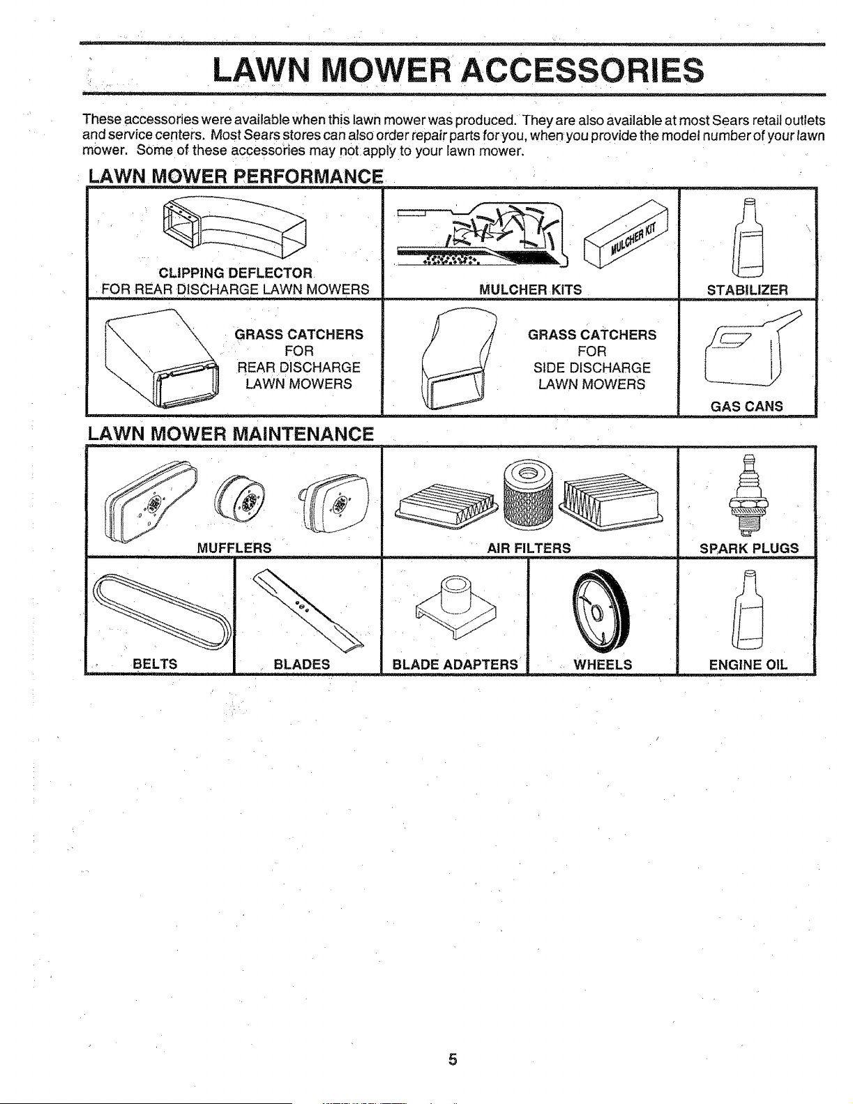
These accessories were available when this lawn mower was produced. They are also available at most Sears retail outlets
and service centers. Most Sears stores can also order repair parts foryou, when you provide the model number of your tawn
mower. SOme of these accessories may not.apply to your lawn mower.
LAWN MOWER PERFORMANCE
CLIPPING DEFLECTOR
FOR REAR DISCHARGE LAWN MOWERS
\
\
\
GRASS CATCHERS
FOR
REAR DISCHARGE
LAWN MOWERS
MULCHER KITS
GRASS CATCHERS
FOR
SIDE DISCHARGE
LAWN MOWERS
LAWN MOWER MAINTENANCE
MUFFLERS
rl ....... i i , i i
AIR FILTERS
BELTS
r " ,
BLADES
BLADE ADAPTERS WHEELS
STABILIZER
GAS CANS
SPARK PLUGS
ENGINE OIL
i LLI: l,_l_'l,_l__ j,[ LJJJ I' ,J
5
LY
Read these instructions and this manual in its entirety
before you attempt to assemble or operate your new lawn
mower. Your new lawn mower has been assembled at the
factory with the exception of those parts left unassembled
for shipping purposes. All parts such as nuts, washers,
bolts, etc., necessary to complete the assembly have been
placed in the parts bag. To ensure safe and proper
operation of your lawn mower, all parts and hardware you
assemble must be tightened securely. Use the correct
tools as necessary to ensure proper tightness.
TO REMOVE LAWN MOWER FROM
CARTON
Remove loose parts included with mower.
Cut down two end corners of carton and lay end panel
down flat,
° Remove all packing materials except padding between
upper, and lower handle and padding holding operator
presence control bar to upper handle.
o Roll lawn mower out of carton and check carton thor-
oughly for additional loose parts,
HOWTO SET UPYOUR LAWN MOWER
TO UNFOLD HANDLE (See Fig. 1)
iMPORTANT: UNFOLD HANDLES CAREFULLY SO AS
NOT TO PINCH OR DAMAGE CONTROL CABLES.
= Raise handles until lower handle section locks into
place in mowing position.
•Raise upper handle section into place on lower handle,
remove protective padding and tighten both handle
knobs.
Remove handle padding holding operator presence
control bar to upper handle.
- Your lawn mower handle can be adjusted for your
mowing comfort. Refer to "Adjust Handle" in the
Service and Adjustment section of this manual.
OPERATOR PRESENCE
CONTROL BAR
UPPER HANDLE
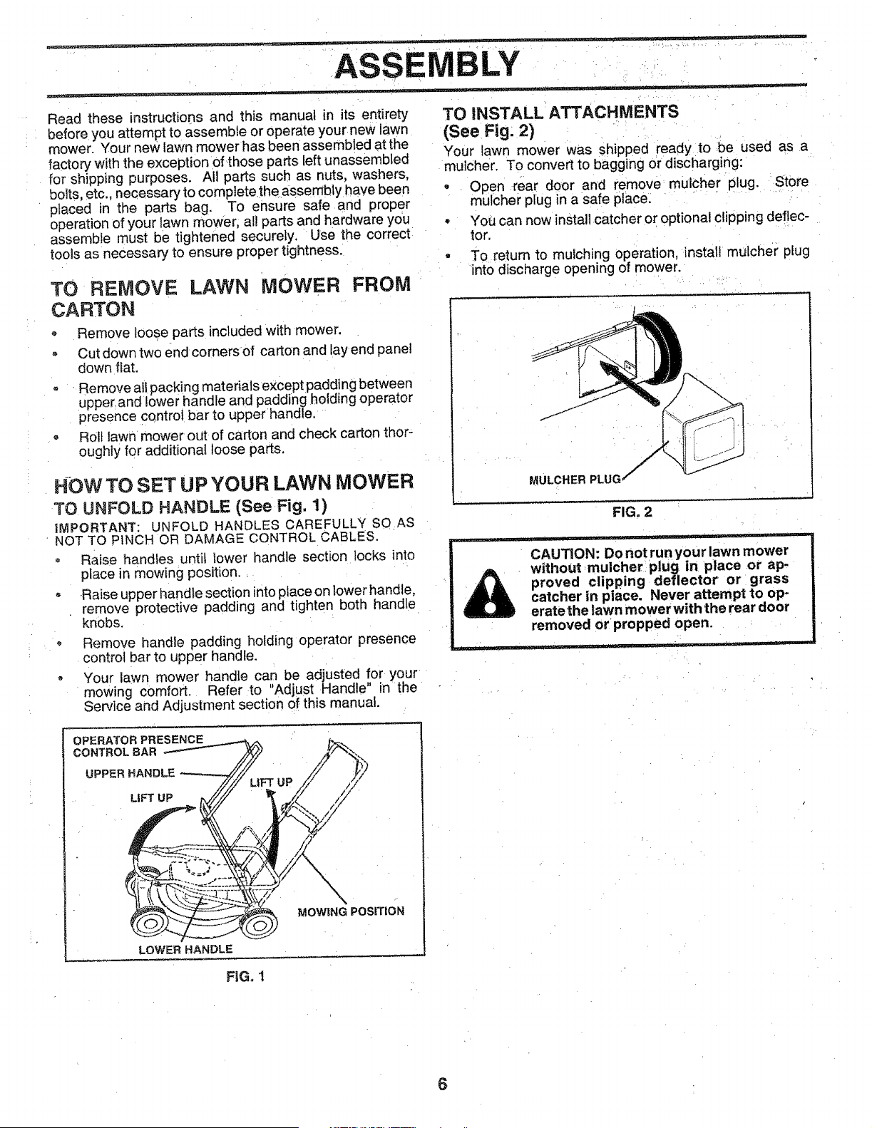
TO iNSTALL ATTACHMENTS
(See Fig: 2)
Your lawn mower was shipped ready to be used as a
mu]cher. To convert to bagging or discharging:
- Open rear door and remove mulcher plug. Store
mulcher plug in a safe place:
• YoU can now install catcher or optional clipping deflec-
tor,
• To return to mulching operation, install mulcher plug
into discharge opening of mower.
MULCHER PLUG
FIG. 2
__ i i i ,
CAUTION: Do not run your lawn mower
without mulcherlplug in place or ap-
proved clipping deflector or grass
catcher in place. Never attempt to op-
eratethe lawn mower with the rear door
removed or propped open.
MOWING POSITION
LOWER HANDLE
FiG. 1
6
, p i i,,,, J _ ...... _ .... : =_ _ _ _.................... _ .....................
LY
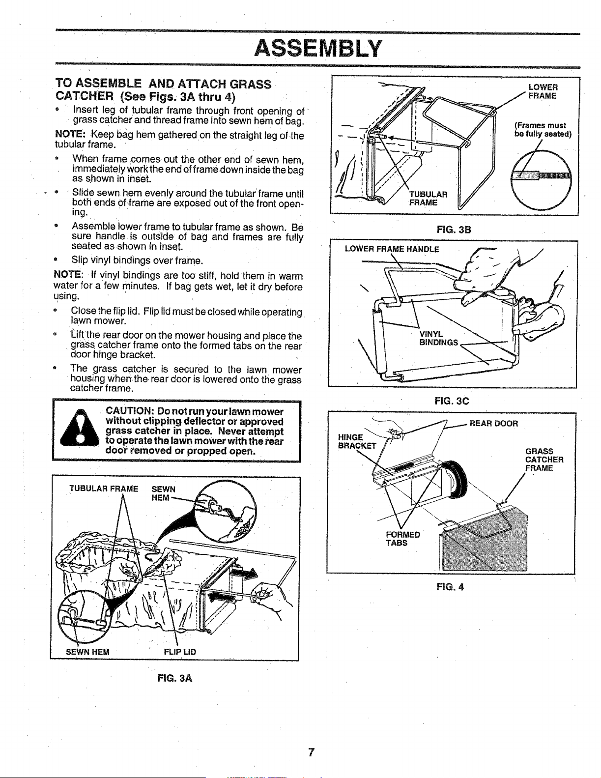
TO ASSEMBLE AND ATTACH GRASS
CATCHER (See Figs. 3A thru 4)
o Insert leg of tubular frame through front opening of
grass catcher and thread frame into sewn hem of bag.
NOTE: Keep bag hem gathered on the straight leg of the
tubular frame.
o When frame comes out the other end of sewn hem,
immediately work the end of frame down inside the bag
as shown in inset.
• StJde sewn hem evenly around the tubular frame until
both ends of frame are exposed out of the front open-
ing.
• Assemble lower frame to tubular frame as shown. Be
sure handle is outside of bag and frames are fully
seated as shown in inset.
= Slip vinyl bindings over frame.
NOTE: If vinyl bindings are too stiff, hold them in warm
water for a few minutes. If bag gets wet, let it dry before
using.
• Closethe fliplid. Flip lid must be closed while operating
lawn mower.
- Lift the rear door on the mower housing and place the
grass catcher frame onto the formed tabs on the rear
door hinge bracket.
• The grass catcher is secured to the lawn mower
housing when.the, rear door is lowered onto the grass
catcher frame.
SEWN HEM
L L
r ' ' I ' _ _,,nnnr L
CAUTION: Do not run your lawn mower
without clipping deflector or approved
grass catcher in place. Never attempt
to operate the lawn mower with the rear
door removed or propped open,
i rl i, j L
TUBULAR FRAME SEWN
FLIP LID
LOWER
FRAME
(Frames must
be fulty seated)
TUBULAR
FRAME
FIG, 3B
LOWER FRAME HANDLE
\
BRACKET
FIG. 3C
REAR DOOR
GRASS
CATCHER
FRAME
FORMED
TABS
FIG. 4
FIG. 3A
7
• _ •..... - - ..... = ...... . .......
OPE O
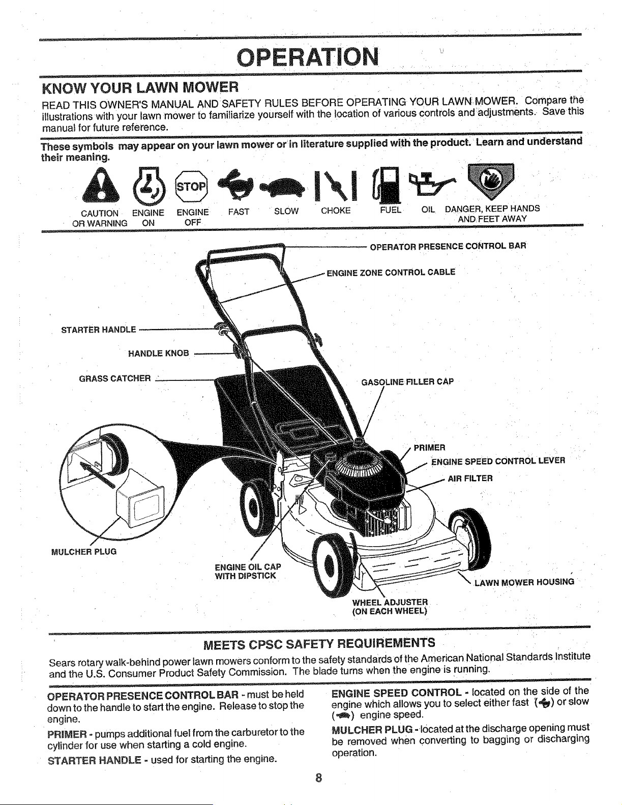
KNOW YOUR LAWN MOWER
READ THIS OWNER'S MANUAL AND SAFETY RULES BEFORE OPERATING YOUR LAWN.MOWER. Compare the
illustrationswith your lawn mower to familiarize yourself with the {ocation of various controls and adjustments._ Save this
manua! for future reference.
These symbo|s may appear on your lawn mower or_in literature supplied with the product. Learn and understand
their meaning.
CAUTION ENGINE ENGINE FAST SLOW CHOKE FUEL OIL DANGER, KEEP HANDS
OR WARNING ON OFF AND FEET AWAY
OPERATOR PRESENCE CONTROL BAR
CONTROL CABLE
STARTER HANDLE
HANDLE KNOB-
GRASSCATCHER
GASOLINE FILLER CAP
/
PRIMER
ENGINE SPEED CONTROL LEVER
AIR FILTER
MULCHER PLUG
ENGINE OIL CAP
WITH DIPSTICK
LAWN MOWER HOUSING
WHEEL ADJUSTER
(ON EACH WHEEL)
MEETS CPSC SAFETY REQUIREMENTS
Sears rotary walk-behind power lawn mowers conform to the safety standards of the American National Standards institute
and the U.S. Consumer Product Safety Commission. The blade turns when the engine is running.
OPERATOR PRESENCE CONTROL BAR -must be held ENGINE SPEED CONTROL = located on the side of the
down to the handle to start the engine. Release to stop the
engine.
PRIMER - pumps additional fuel from the carburetor to the
cylinder for use when starting a cold engine.
STARTER HANDLE - used for starting the engine.
engine which allows you to select either fast (,_) or slow
(-_) engine speed.
MULGHER PLUG-located at the discharge opening must
be removed when converting to bagging or discharging
operation.
8
OPERATION
__ The operation of any lawn mower can-result in foreign objects-_th-ro-_
I [r_ result ih severe eye damage. Always wear safety glasses or eye shietds white operating your J
I L=.._l=.--_ lawn mower or performing any adjustments or repairs. We recornmenda wide vision safety J
I _ mask over the pectacles or stand_ rdsafety glasses.
HOW TO USE YOUR LAWN MOWER
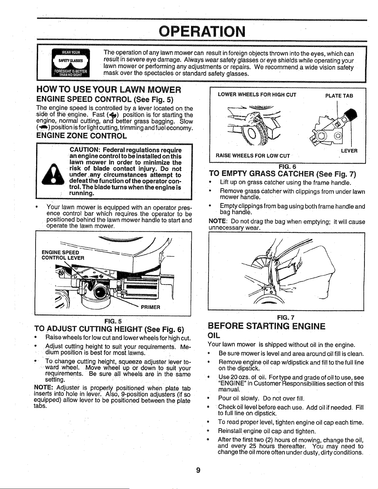
ENGINE SPEED CONTROL (See Fig. 5)
The engine speed is controlled by a lever located on the
side of theengine. Fast (,_) position is for starting the
engine, normal cutting, and better grass bagging. Slow
(,_) position isfor lightcutting,trimming andfue! economy.
ENGINE ZONE CONTROL
CAUTION: Federal regulations require
an engine control to be installed on this
lawn mower in order to minimize the
risk of blade contact injury, Do not
under .any circumstances attempt to
defeat the function of the operator con-
troL The blade turns when the engine is
running.
, JL .... =
Your lawn mower is equipped with an operator pres-
ence control bar which requires the operator to be
positioned behind the lawn mower handle to start and
operate the lawn mower,
LOWER WHEELS FOR HIGH CUT
PLATE TAB
LEVER
RAISE WHEELS FOR LOW CUT
FIG. 6
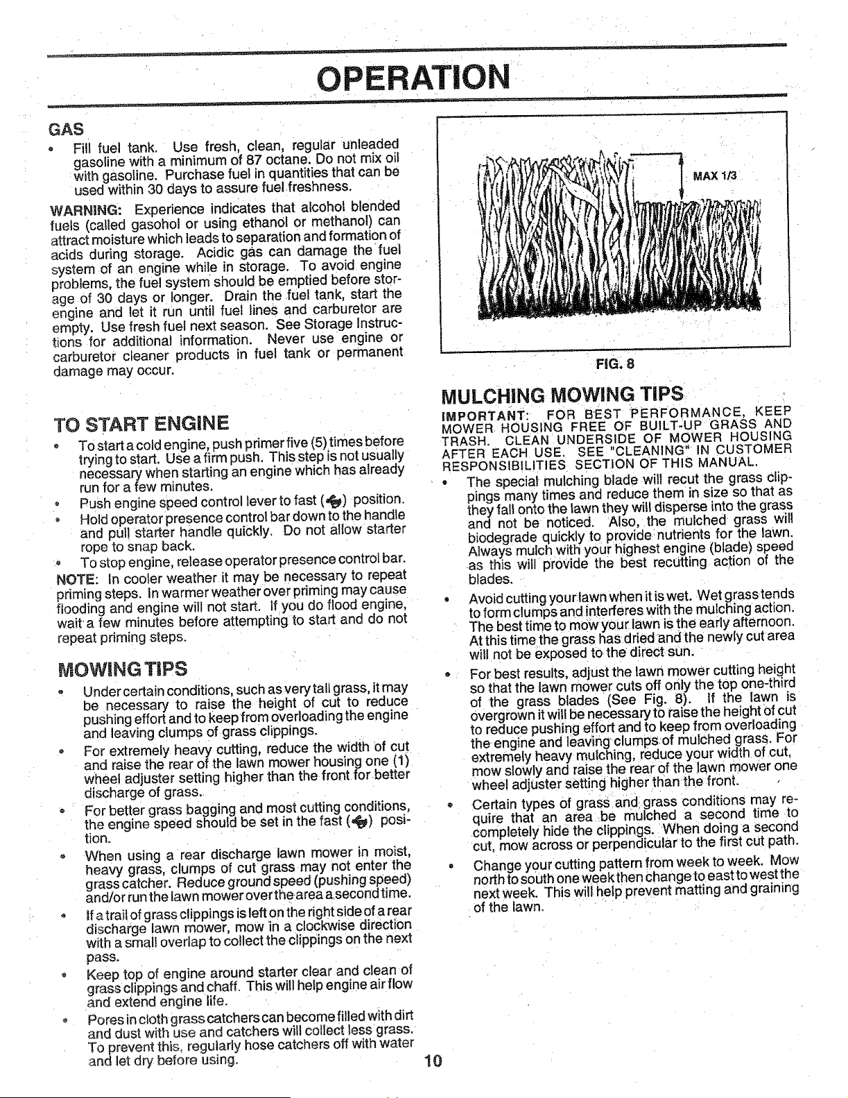
TO EMPTY GRASS CATCHER (See Fig. 7)
- Lift up on grass catcher using the frame handle.
• Remove grass catcher with clippings from under lawn
mower handle,
- Emptyclippingsfrombag using bothframe handleand
bag handle,
NOTE: Do notdragthe bag when emptying; it willcause
unnecessary wear,
ENGINE SPEED
CONTROLLEVER
PRIMER
FIG. 5
TO ADJUST CUTTING HEIGHT (See Fig. 6)
• Raise wheels for low cut and lower wheels forhigh cut.
• Adjust cutting height to suit your requirements. Me-
dium positionis best for most awns.
• Tochange cutting height, squeeze adjuster lever to-
ward wheel. Move wheel up 'or down to suit your
requirements. Be sure all wheels are in the same
setting. :
NOTE: Adjuster is properly positioned when plate tab
inserts into h0le in iever_ Also, 9-position adjusters (if so
equipped) aglow lever tO be positioned between the plate
tabs,
FIG. 7
BEFORE STARTING ENGINE
OIL
Your lawn mower is shipped without oil in the engine.
, Be sure mower is level and area around oil fill is clean,
• Remove engine oil cap w/dipstick and fil! to the full line
on the dipstick.
• Use 20 ozs. of oil. For type and grade of oil to use, see
"ENGINE" in Customer Responsibilities section of this
manual,
• Pour oil slowly, Do not over fill.
. Check oil level before each use, Add oil if needed. Fill
to full line on dipstick,
• To read proper level, tighten engine oil cap each time.
. ReinstaIlengine oil cap and tighten.
. After the first two (2) hours of mowing, change the oil,
and every 25 hours thereafter, You may need to
change the oil more often under dusty, dirty conditions.
9
OPERATION
GAS
- Fill fuel tank. Use fresh, clean, regular unleaded
gasoline with a minimum of 87 octane: Do not mix oil
with gasoline. Purchase fuel in quantities that can be
used within 30 days to assure fuel .freshness,
WARNING: Experience indicates that alcohol blended
fuels (called gasohol or using ethanol or methanol) can
attract moisture which Jeads to separation and formation of
acids during storage. Acidic gas can damage the fuel
system .of an engine while in storage. To avoid engine
problems, the fuel system should be emptied before stor-
age of 30 days or longer. Drain the fuel tank, start the
engine and let it run until fuel lines and carburetor are
empty. Use fresh fuel next season. See Storage Instruc-
tions for additional information. Never use engine or
carburetor cleaner products in fuel tank or permanent
damage may occur.
MAX 1/3
FIG, 8
TO START ENGINE
To start a cold engine, push primer five (5) times before
trying to start. Use a firm push. This step is not usually
necessary when starting an engine which has already
run for a few minutes.
o Push engine speed control lever to fast (_) position.
• Hold operator presence control bar down to the handle
and pull starter handle quickly. Do not altowstarter
rope to snap back,
o To stop engine, release operator presence control bar.
NOTE: In cooler weather it may be necessary to repeat
priming steps. In warmer weather over priming may cause
flooding and engine will not start. Ifyou do flood engine,
waffa few minutes before attempting to start and do not
repeat priming steps.
MOWINGTIPS
0
Under certain conditions, such as very tall grass, it may
be necessary to raise the height of cut to reduce
pushing effort and to keep from overloading the engine
and leaving clumps of grass clippings.
For extremely heavy cutting, reduce the width of cut
and raise the rear of the lawn mower housing one (1)
whee! adjuster setting higher than the front for.better
discharge of grass..
For better grass bagging and most cutting conditions,
the engine speed should be set in the fast (,#_) posi-
tion.
When using a rear discharge lawn mower in moist,
heavy grass, clumps of cut grass may not enter the
grass catcher. Reduce ground speed (push ng speed)
and/or run the lawn mower over thearea asecond time.
Ifa trai! of grass c!ippings is left on the right side of a rear
discharge !awn mower, mow in a clockwise direction
with a small overlap to collect the clippings on the next
pass.
Keep top of engine around starter clear and clean of
grass clippings and chaff, This wilt help engine air flow
and extend engine life. : '
Pores incloth grass catchers can become filled with dirt
and dust with use and catchers will collect less grass.
To prevent this, regularly hose catchers off with water
and let dry before using.
10
MULCHING MOWING TIPS
IMPORTANT: FOR BEST PERFORMANCE, KEEP
MOWER HOUSING FREE OF BUILT-UP GRASS AND
TRASH. CLEAN UNDERSIDE OF MOWER HOUSING
AFTER EACH USE. SEE "CLEANING" IN CUSTOMER
RESPONSIBILITIES SECTION OF THIS MANUAL,
• The special mulching blade wilt recut the grass clip-
pings many times and reduce them in size so that as
they fal! onto the lawn they witldisperse into the grass
and not be noticed. Also, the mulched grass will
biodegrade quickly to provide: nutrients for the lawn.
Always mulch with yourhighest engine (blade) speed
.as this w I provide the best rectJtting act on of the
blades.
Avoid cutting yourtawn when it is wet. Wet grasstends
to form clumps and interferes with the mulching action.
The best time to mow you_ lawn is the early afternoon.
At this time the grass has dried and the newly cut area
will not be exposed tO,the d!rect sun.
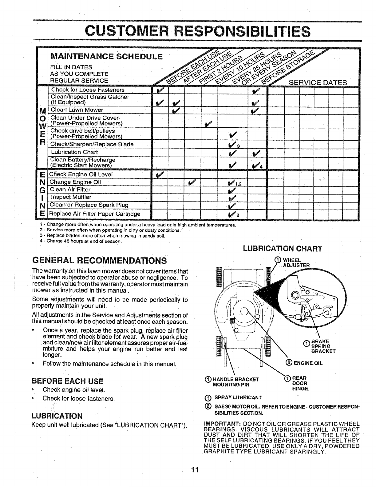
For best results, adjust the lawn mower cutting :height
so that the lawn mower cuts off only the top one-third
of the grass blades (See Fig. 8). If the lawn is
Overgrown it wiill be necessary to raise the height Of cut
to reduce pushing effort and to keep from overloading
the.engine and I_aving clumps.of mulched grass. For
extremely heavy mulching, reduce your width of cut,
mow slowly and raise the rear of the lawn mower one
whee adjuster setting higher than'the:front. ,
Certain types of grasSandigrass conditions may re-
quire that an area:be mulched a second time to
completely hide the clippings. When doing a second
cut, mow across or perpendicL_!arto the first cut path.
Change your cutting pattern from week to week. Mow
north to south one weekthen Change to east to west the
next week. This will help pre_!ent matting and :graining
of the lawn. ....
ILIT
MAINTENANCE SCHEDULE
FILL tN DATES
AS YOU COMPLETE
REGULAR SERVICE
Check for Loose Fasteners v'
Clean/Inspect Grass Catcher
. (If Equipped) 'i if if
IV_ Clean Lawn M°wer
wO Clean Under Drive cover
(Power-Propelled Mowers)
Check drive belt/pulleys
RE (Power-Propelled Mowers)
CheckiSha[pen/Replace Blade
Lubrication Chart
v'
SERVICE DATES
v'
v'
v'
E CSeck Elngine Oil Level _
N_ine Oil :' " _ ' 1_1,2
G Clean Air Filter
I inspect Muffler
N i Clean or Replace Spark Pug " ................. if
E Replace Air Filter Paper Cartridge ........ !_2
1 - Change more often when operating under a heavy load or in high ambient temperatures.
2 - Service more often when operating _n dirty or dusty conditions,
3 - Replace blades more often when mowing in sandy soil.
4 - Charge 48 hours at end of season.
..... i....
v'
LUBRICATION CHART
GENERAL RECOMMENDATIONS
The warranty on this lawn mower does not cover items that
have been subjected to operator abuse or negligence. To
receive full value from the warranty, operator must maintain
mower as instructed in this manual.
Some adjustments will need to be made periodically to
properly maintain your unit.
All adjustments in the Service and Adjustments section of
this manual should be checked at least once each season.
• Once a year, replace the spark plug, replace air filter
element and check blade for wear. A new spark plug
and clean/new air filter element assures proper air-fuel
mixture and helps your engine run better and last
longer.
= Foitow the maintenance schedule in this manual.
BEFORE EACH USE
• Check engine oil level.
• Check for loose fasteners,
LUBRICATION
Keep unit welt lubricated (See "LUBRICATION CHART").
WHEEL
ADJUSTER
(_) BRAKE
SPRING
BRACKET
(_) ENGINE OIL
(_ HANDLE BRACKET REAR
MOUNTING PIN DOOR
HINGE
(_) SPRAY LUBRICANT
® SAE 30 MOTOR OIL. REFER TO ENGINE- CUSTOMER RESPON-
SIBILITIES SECTION.
iMPORTANT: DO NOT OiL OR GREASE PLASTIC WHEEL
BEARINGS. VISCOUS LUBRICANTS WILL ATTRACT
DUST AND DIRT THAT WILL SHORTEN THE LIFE OF
THE SELF LUBRICATING BEARINGS_ iF YOU FEE L THEY
MUST BE LUBRICATED, USE ONLY A DRY, POWDERED
GRAPHITE TYPE LUBRICANT SPARINGLY.
11
_ - . _ __ _ . _ _ _ . ; m i ..,i ..... _ .... i Jut __±._. _,r
CUSTOMER RESPONSIBI
LAWN MOWER
Always observe safety rules when performing any mainte-
Fiance.
TIRES
- Keep tires free of gasoline, oil, or insect control chemi-
cals which can harm rubber.
Avoid stumps, stones, deep ruts, sharp objects and
other hazards that may cause tire damage.
BLADE CARE
For best results, mower blade must be kept sharp. Replace
bent or damaged blades;
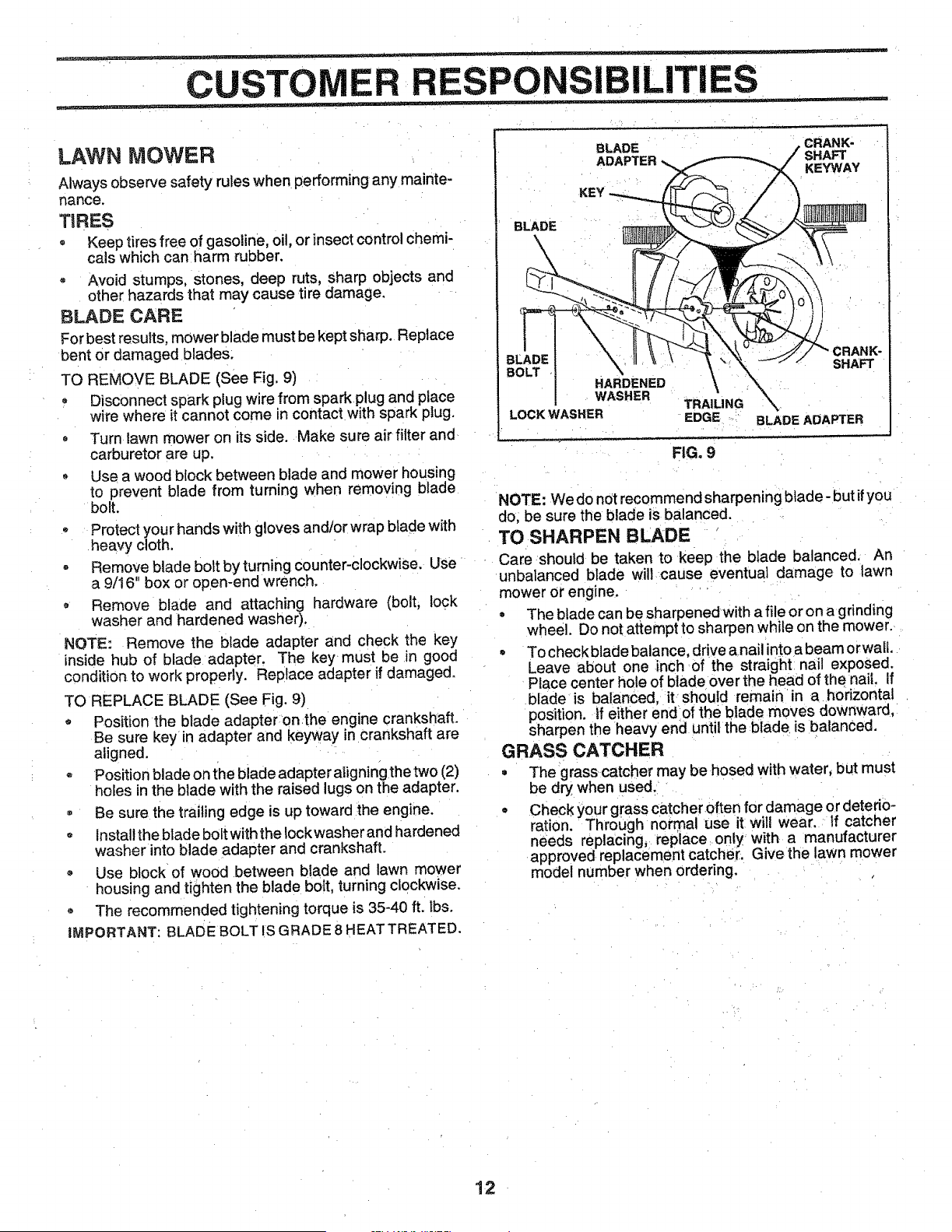
TO REMOVE BLADE (See Fig, 9)
- Disconnect spark plug wire from spark plug and place
wire where it cannot come in contact with spark plug,
• Turn lawn mower on its side. Make sure air filter and
carburetor are up.
- Use a wood block between blade and mower housing
to prevent blade from turning when removing blade
bolt,
o Protect your hands with gloves and/or wrap blade with
heavy cloth.
• Remove blade boft by turning counter-clockwise, Use
a 9/16" box or open-end wrench,
• Remove blade and attaching hardware (bolt, lock
washer and hardened washer).
NOTE: Remove the blade adapter and check the key
inside hub of blade adapter. The key must be in good
condition to work properly. Replace adapter if damaged.
TO REPLACE BLADE (See Fig, 9)
- Position the blade adapteronthe engine crankshaft,
Be sure key in adapter and keyway in crankshaft are
aligned.
Position blade on the blade adapter atigning the two (2)
holes in the blade with the raised lugs on the adapter,
- Be sure the trailing edge is up toward the engine.
install the blade bolt with the Iockwasher and hardened
washer into blade adapter and crankshaft,
Use block of wood between blade and lawn mower
housing and tighten the blade bolt, turning clockwise.
o The recommended tightening torque is 35-40 ft, lbs,
iMPORTANT: BLADE BOLT IS GRADE 8 HEAT TREATED.
BLADE CRANK-
ADAPTER SHAFT
KEYWAY
BLADE
BL SHAFT
B(
HARDENED
WASHER
TRAILING
LOCK WASHER EDGE BLADE ADAPTER
FIG. 9
NOTE: We do not recommend sharpening blade- but ifyou
do, be sure the blade is balanced.
TO SHARPEN BLADE
Care should be taken to keep the blade balanced. An
unbalanced blade wilt cause eventual damage to lawn
mower or engine.
• The blade can be sharpenedwith a file or on a grinding
wheel. Do not attempt to sharpen while on the mower.
° To check blade balance, drive a nail into a beam orwall,
Leave about one inch of the straight nail exposed.
Place center hole of blade over the head of the nail, If
blade is balanced, it should remain in a horizontal
position, If either end of the blade moves downward,
sharpen the heavy end until the blade is balanced,
GRASS CATCHER
= The grass catcher may be hosed with water, but must
be dry. when used.
- Check your grass catcher often for damage or deterio-
ration. Through normal use it will wear. If catcher
needs replacing_ replace onty with a manufacturer
approved replacement catcher. Give the lawn mower
model number when ordering.
12 ¸
CUSTOMER ESPO LITIES
ENGINE ....
LUBRICATION
Use only high quality detergent oil rated with AP! service
classification SF or SG, Select the 0il's SAE viscosity grade
according to your expected operating temperature;
SAE ViSCOSiTY GRADES
_0 _ 0 o _ 60 _
.30_ .20_ .10° 0° 10 _ 20° 30 ° 40_
TEMPERATURE RANGE ANTICIPATED BEFORE NEXT OIL CHANGE
NOTE: Although multi-viscosity oiJs (5W30, 10W30 etc,)
improVe starting in cold weather, these multi-viscosity oils
will result in increased oii consumption when used above
32°F, Check your engine oil leve! more frequently to avoid
possible engine damage from running low on oil.
Change the oil after the first two hours of operation and
every 25 hours thereafter or at least once a year ifthe lawn
mower is not used for 25 hours in one year,
Check the crankcase oil level before starting the engine
and after each five (5) hours of continuous use, Tighten oi!
plug securely each time you check the oil level
TO CHANGE ENGINE OiL (See Fig. !0)
NOTE: Before tipping lawn mower to drain oil, drain fuet
tank by running engine until fuel tank is empty,
, Disconnect spark plug wire from spark plug and place
wire where it cannot come in contact with spark plug,
, Remove engine oil cap; lay aside on a clean surface.
• Tip lawn mower on its side and drain oil into a suitable
container, Rock lawn mower back and forth to remove
any oil trapped inside of engine,
• Wipe off any spilled oil on lawn mower and on side of
engine.
• Fill engine with oil. Fill on!y to the "FULL" line on the
dipstick, DO NOT OVER FtLLo
. Replace engine oil cap.
• Reconnect spark plug wire to spark plug,
CONTAINER
FiG, 10
13
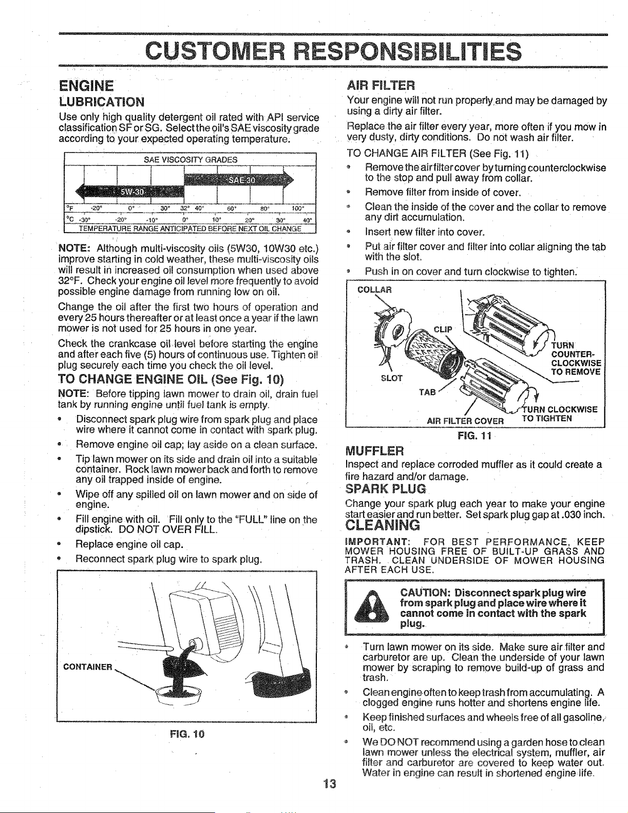
AUK FILTER
Your engine will not run properly,and may be damaged by
using a dirty air filter.
Replace the air filter every year, more often if you mow in
yeFy dusty, ditty conditions, Do not wash air _ter,
TO CHANGE AIR FILTER (See Fig, 11)
Remove the a:irfitter cover by tu rning counterclockwise
to the stop and pull away from collar,
Remove filter from inside of cover.
o Clean the inside of the cover and the collar to remove
any dirt accumulation,
o Insett new filter into cover,
Put ai:rfilter cover and filter into collar aligning the tab
with the slot,
o Push in on cover and turn clockwise to tighten.
COLLAR
SLOT
TAB
COUNTER-
CLOCKWISE
TO REMOVE
AiR FILTER COVER TO TIGHTEN
FiG. 11
MUFFLER
Inspect and replace corroded muffler as it could create a
fire hazard and/or damage.
SPARK PLUG
Change your spark plug each year to make your engine
start easier and run better, Set spark plug gap at .030 inch,
CLEANING
IMPORTANT: FOR BEST PERFORMANCE. KEEP
MOWER HOUSING FREE OF BUtLT-UP GRASS AND
TRASH, ,CLEAN UNDERSIDE OF MOWER HOUSING
AFTER EACH USE.
CAUTION: Disconnect spark plug wire
from spark plug and place wire where it
cannot come in contact with the spark
plug.
Turn lawn mower on itsside,Make sureairfilterand
Carburetor are up, Clean theunderside of your lawn
mower by scraping to remove build-up of gross and
trash,
Clean engineoften to keep trash from accumulating. A
clogged engine runs hotter and shortens engine life,
Keep finished surfaces and wheels free of all gasoline,>
oit, etc.
o We DO NOT recommend using a garden hose to clean
lawn mower unless the electrical system, muffler, air
filter and carburetor are covered to keep water out.
Water in engine can result in shortened engine,life.
CE ADJUSTM
DJUSTMENTS: ' ' "
I have. pieto,ystopped.
, Disconnect spark p!ug wire from spark plug and place where it cannot come in co , i ,
LAWN MOWER
TO ADJUST CUTTING HEIGHT
See "TO ADJUST CUTTING HEIGHT" in the Operation
section of this manual.
REAR DEFLECTOR
The rear deflector, attached between the rear wheels of
your lawn mower, is provided to minimize the possibility
that objects will be thrown out the rear of the lawn mower
into the operator's mowing position.
If the rear deflector becomes damaged, it should be re-
placed,
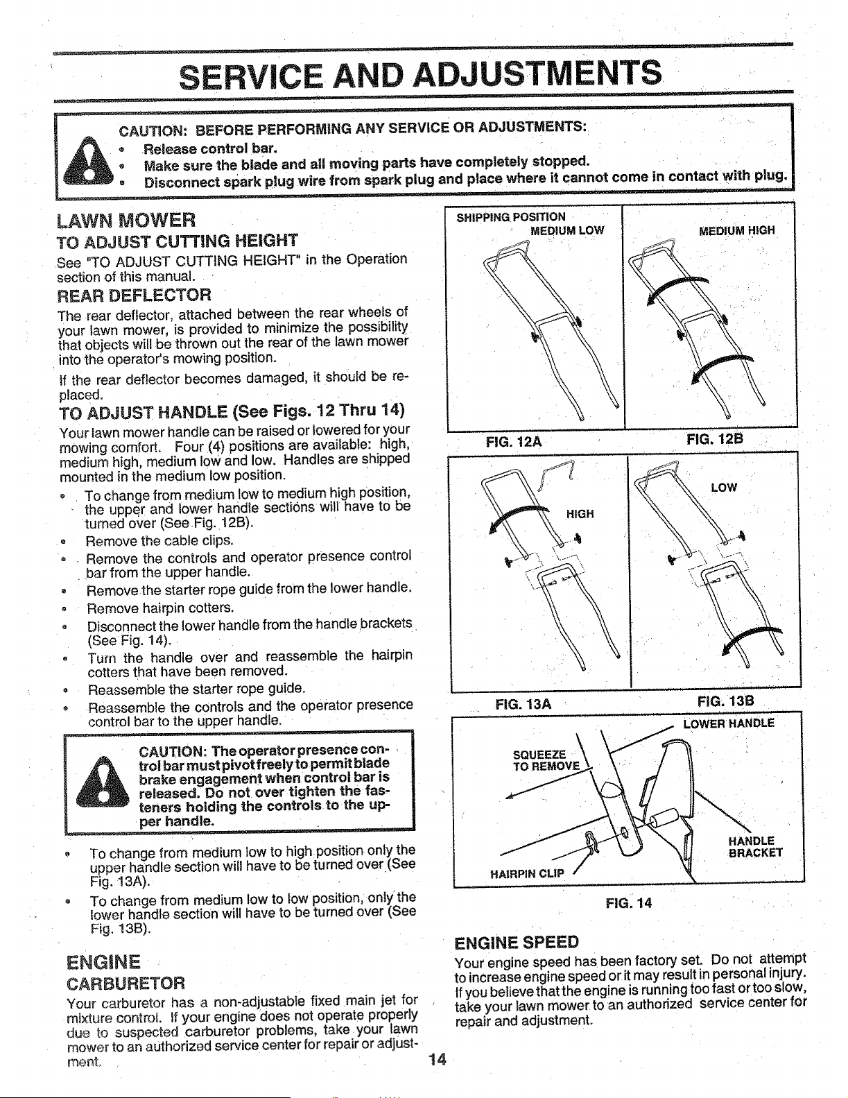
TO ADJUST HANDLE (See Figs. 12 Thru 14)
Your lawn mower handle canbe raised or lowered for your
mowing comfort. Four (4) positions are available: high,
medium high, medium low and low. Handles are shipped
mounted in the medium low position.
° To change from medium low to medium high position,
the upp_tr and lower handte sectk_ns will have to be
turned over (SeeFig. 12B).
o Remove the cable clips.
o Remove the controls and operator presence control
bar from the upper handle.
• Remove the starter rope guide from the lower handle.
- Remove hairpin cotters.
, Disconnect the lower handle from the handle brackets
(See Fig. 14).
° Turn the handle over and reassemble the hairpin
cotters that have been removed.
• Reassemble the starter rope guide.
- Reassemble the controls and the operator presence
control bar to the upper handle,
CAUTION: The operator presence con-
trol bar must pivot freely to permit blade
brake engagement when control bar is
released. Do not over tighten the fas-
teners holding the controls to the up-
per handle.
__ _ . -.J ...... L = -- _ - --- " =
• To change from medium low to high position only the
upper handle section will have to be turned over (See
Fig. 13A).
o To change from medium low to Iow position, only the
lower handle section will have to be turned over (See
Fig, t3B).
ENGINE
CARBURETOR
Your carburetor has a non-adjustable fixed main jet for
mixture control, tf your engine does not operate properly
due to suspected carburetor problems, take your lawn
mower to an authorized service center for repair or adjust-
ment,
14
SHIPPING. POSITION
MEDIUM LOW
FIG. 12A
FIG. 13A
MEDIUM HIGH
J
FIG. 12B
LOW
.... i .,
FIG. 13B
SQUEEZE
TO REMOVE
HAIRPIN CLIP
FIG. 14
ENGINE SPEED
Your engine speed has been factory set. Do not attempt
to increase engine speed or it may result in personal injury.
If you believe that the engine is running too fast or too slow,
take your lawn mower to an authorized service center for
repair and adjustment.
STORAGE
Immediately prepare your lawn mower for storage at the
end of the season or if the unit will not be used for 30 days
or mOre.
LAWN MOWER
When lawn mower is to be stored for a period of time, clean
it thoroughly, remove all dirt, grease, leaves, etc. Store in
a clean, dry area.
Clean entire lawn mower (See "CLEANING!' in the
Customer Responsibilities section of this manual).
Lubricate as shown in the Customer Responsibilities
section of this manual.
, Be sure that all nuts, bolts, screws, and pins are
securely fastened. Inspect moving parts for damage,
breakage and wear. Replace if necessary.
• Touch up all rusted or chipped paint surfaces; sand
lightly before painting.
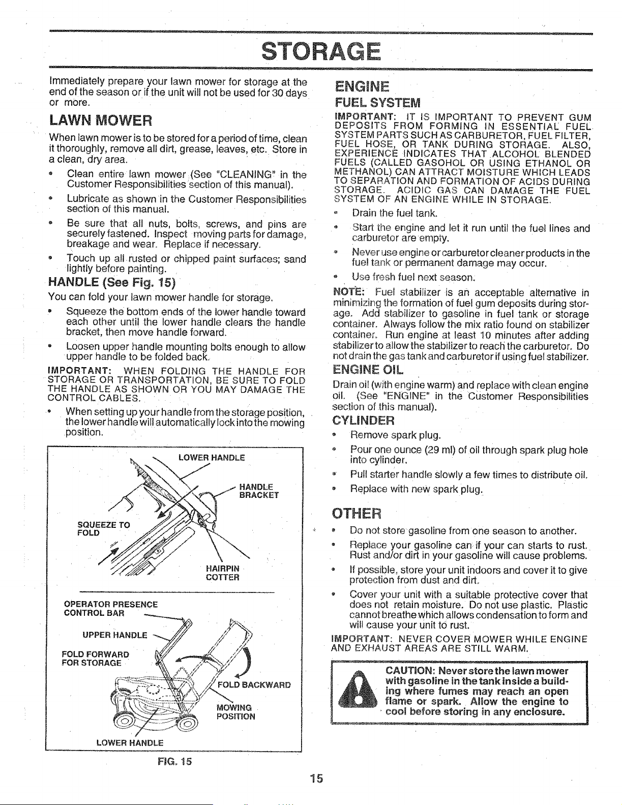
HANDLE (See Fig. t5)
You can fold your lawn mower handle for storage.
, Squeeze the bottom ends of the lower handle toward
each other until the lower handle clears the handle
bracket, then move handle forward.
Loosen upper handle mounting bolts enough to allow
upper handle to be folded back,
IMPORTANT: WHEN FOLDING THE HANDLE FOR
STORAGF OR TRANSPORTATION, BE SURE TO FOLD
THE HANDLE AS SHOWN OR YOU MAY DAMAGE THE
CONTROL CABLES.
• When setting up you r hand e from the storage pos!tion,
the lower handle will automatically lock into the mowing
position.
LOWER HANDLE
SQUEEZE TO
FOLD
HAIRPIN
COTTER
OPERATOR PRESENCE
CONTROL BAR
UPPER HANDL _ //9 _,")
FOR STORAGE ' ,_, "_
LOWER HANDLE
ENGINE
FUEL SYSTEM
iMPORTANT: iT IS IMPORTANT TO PREVENT GUM
DEPOSITS FROM FORMING IN ESSENTIAL FUEL
SYSTEM PARTS SUCH AS CARBURETOR, FUEL FILTER,
FUEL HOSE, OR TANK DURING STORAGE. ALSO,
EXPERIENCE INDICATES THAT ALCOHOL BLENDED
FUELS (CALLED GASOHOL OR USING ETHANOL OR
METHANOL) CAN ATTRACT MOISTURE WHICH LEADS
TO SEPARATION AND FORMATION OF ACIDS DURING
STORAGE. ACIDIC GAS CAN DAMAGE THE FUEL
SYSTEM OF AN ENGINE WHILE IN STORAGE.
o Drain the fuet tank,
Start the engine and let it run until the fuel lines and
carburetor are empty.
Never use engine or carburetor cleaner products in the
fuel ta_Tkor permanent damage may occur.
Use fresh fuel next season,
NOT-E: Fuel stabilizer is an acceptable alternative in
minimizing the formation of fuel gum deposits during stor-
age, Add st_abitizer to gasoline in fue! tank or storage
container, Always follow the mix ratio found on stabilizer
container, Run engine at least 10 minutes after adding
stabilizer to allow the stabilizer to reach the carburetor, Do
not d rain the gas tank and carburetor if using fuel stabilizer.
ENGIINE OIL
Drain oil (with engine warm) and replace with clean engine
oil. (See "ENGINE" in the Customer Responsibilities
section of this manual).
CYUNDER
Remove spark plug.
• Pour one ounce (29 ml) of oil through spark plug hole
into cylinder.
Pull starter handle slowly a few times to distribute oil,
, Replace with new spark plug,
OTHER
- Do not store gasoline from one season to another.
Replace your gasoline can: if your can starts to rust.
Rust and/or dirt in your gasoline will cause problems.
= If possible, store your unit indoors and cover it to give
protection from dust and dirt
- Cover your unii with a suitable protective cover that
does not retain moisture. Do not use plastic. Plastic
cannot breathe Which allows condensation to form and
wil! cause your unit to rust,
mMPORTANT: NEVER COVER MOWER WHILE ENGINE
AND EXHAUST AREAS ARE STILL WARM,
_nk inside a buildo
_ ing Where fumes may reach an open
_ flame or _loW the engine to
- ----- ' cool before storing in any enclosure.
FJGot5
!5
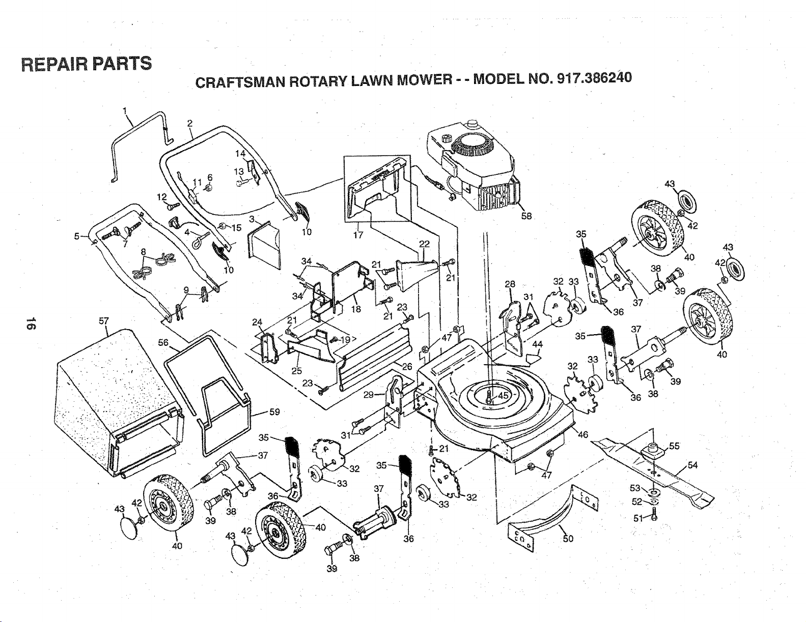
REPAIR PARTS
1
\
CRAFTSMAN ROTARY
2
LAWN MOWER - - MODEL NO. 9!7.386240
.,,J.
57
12
4O
g
38
43
24
17
3g
|
58
35
28 .. 32 33
44
32
36
39
37
37
39
36 38
4,3
40
REPAIR PARTS
KEY PART
NO. NO,
CRAFTSMAN ROTARY LAWN MOWER- = MODEL NO. 917.386240
DESCRiPTiON
KEY' PART DESCRiPTiON
NO. NO,
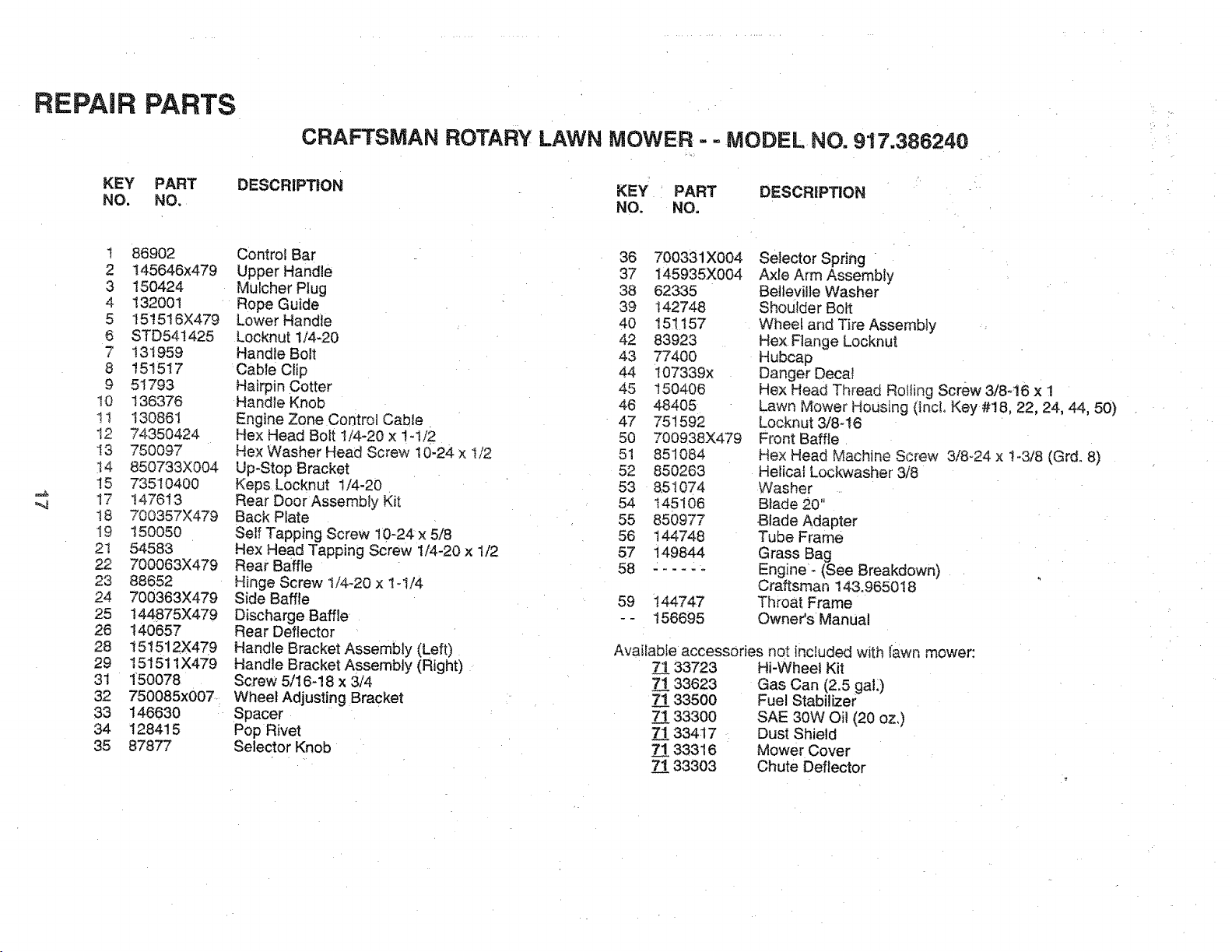
t 86902
2 145646x479
3 150424
4 132001
5 15t516X479
6 STD54!425
7 131959
8 151517
9 51793
I0 136376
tl 130861
12 74350424
I3 750097
14 850733X004
15 73510400
17 147613
!8 700357X479
I9 150050
2t 54583
22 700063X479
23 88652
24 700363X479
25 144875X479
26 140657
28 151512X479
29 15151tX479
31 150078
32 750085x007.:
33 146630
34 128415
35 87877
Control Bar
Upper Handle
Mulcher Plug
Rope Guide
Lower Handle
Locknut 1/4-20
Handle Bolt
Cable Clip
Hairpin Cotter
Handle Knob
Engine Zone Control Cable.
Hex Head Bolt 1/4-20 x 1-I/2
He× Washer Head Screw t0-24 x l/2
Up-Stop Bracket
Keps Locknut 1/4-20
Rear Door Assembly Kit
Back Plate
Self Tapping Screw 10-24x 5/8
Hex Head Tapping Screw t/4-20 x I/2
Rear Baffle
Hinge Screw 1/4-20 x 1-1/4
Side Baffle
Discharge Baffle
Rear Deflector
Handle Bracket Assembly (Left)
Handle Bracket Assembly (Right)
Screw 5/t 6-18 x 3/4
Wheel Adjusting Bracket
Spacer
Pop Rivet
Selector Knob
36 700331X004
37 145935X004
38 62335
39 142748
40 151157
42 83923
43 77400
44 i07339x
45 150406
46 48405
47 751592
50 700938X479
51 851084
52 850263
53 851074
54 145106
55 850977
56 144748
57 149844
58 ......
59 144747
-- 156695
Selector Spring =
Axle Arm Assembly
Belteville Washer
ShoUlder Bolt
Wheel and Tire Assembly
Hex Flange Locknut
Hubcap
Danger Decal
Hex Head Thread Roiling Screw 3/846 x 1
Lawn Mower HoUsing (IncL Key #18, 22, 24, 44, 50)
Locknut 3/8-16
Front Baffle
Hex Head Machine Screw 3/8-24 x 1-3/8 (Grd° 8)
Helical Lockwasher 3/8
Washer
Blade 20"
Blade Adapter
Tube Frame
Grass Bag
Engine'- (See Breakdown)
Craftsman 143.965018
Throat Frame
Owner's Manual
Available accessories not included with lawn mower:
7_133723
7133623
7133500
7_.!.33300
7_:[33417
7_133316
7133303
Hi-Wheel Kit
Gas Can (2,5 gall)
Fuel Stabilizer
SAE 30W Oil (20 oz,)
Dust Shield
Mower Cover
Chute Deflector
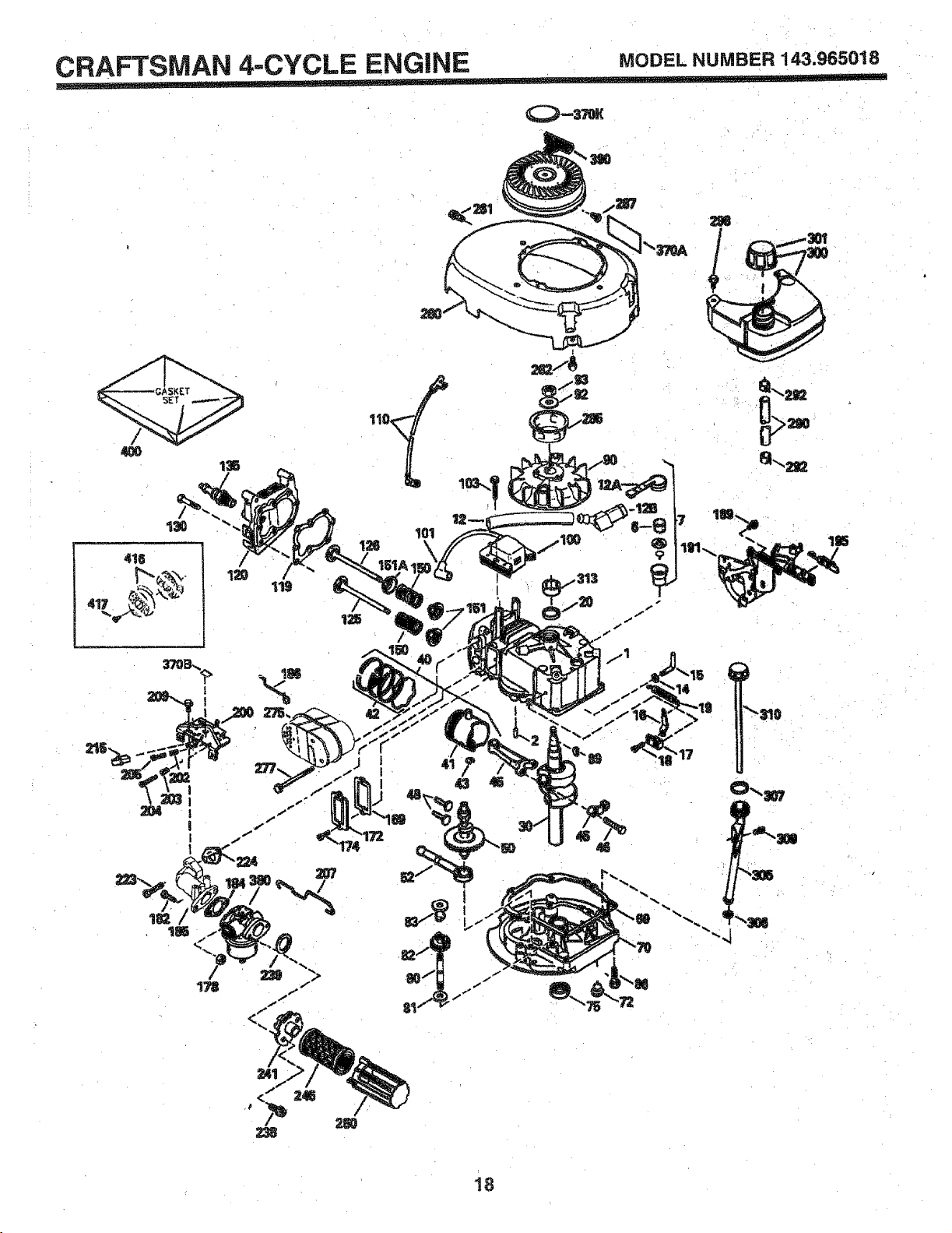
CRAFTSMAN 4,-CYCLE ENGINE MODELNUMBER143,965018
, ,,, ,, ,=
_379K
18
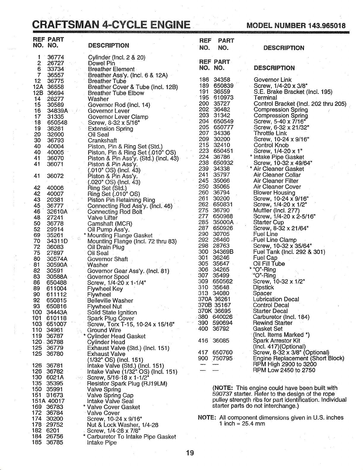
CRAFTSMAN 4oCYCLE ENGINE MODELNUMBER143.96S01S
REF PART REF PART
NO. NO, DESCRIPTION NO, NO. DESCRIPTION
1 36774
2 26727
6 33734
7 36557
12 36775
12A 36558
12B 36694
14 28277
15 30589
16 34839A
17 31335
18 850548
19 38281
20 32600
30 36793
4O 40OO4
40 40005
41 36070
4t 36071
4! 36072
42 40006
42 40007
43 20381
45 36777
46 32610A
48 27241
50 36778
52 29914
69 35261
70 343tlD
72 36083
75 27897
80 30574A
81 30590A
82 30591
83 30588A
86 650488
89 611004
90 611112
92 650815
93 650816
100 34443A
101 610118
103 651007
110 34961
!19 36787
120 36788
125 36779
125 36780
126 36781
126 36782
130 6021A
!35 35395
150 35991
151 31673
151A 40017
169 36783
172 36784
174 30200
178 29752
182 6201
t84 26756
185 36785
Cylinder (Incl. 2 & 20)
Dowet Pin REF PART
Breather Element NO. NO.
Breather Ass'y. (Incl. 6 & 12A)
Breather Tube 186 34358
Breather Cover & Tube (Incl. 12B) 189 650839
Breather Tube Elbow 191 36559
Washer 195 610973
Governor Rod (Incl. 14) 200 35727
Governor Lever 202 36482
Governor Lever Clamp 203 3t 342
Screw, 8-32 x 5/16" 204 650549
Extension Spring 205 650777
Oil Seal 207 34336
Crankshaft 209 30200
Piston, Pin & Ring Set (Std.) 2t5 32410
Piston, Pin & Ring Set (.010" OS) 223 850451
Piston & Pin Ass'y. (Std.) (Incl. 43) 224 36786
Piston & Pin Ass'y. 238 850932
(.010" OS) (incl. 43) 239 34338
Piston & Pin Ass'y. 241 35797
(,020" OS) (Inc!. 43) 245 35066
Ring Set (Std,) 250 35065
Rirjg Set (.010" OS) 260 36794
Piston Pin Retaining Ring 261 30200
Connecting Rod Ass'y. (Inci. 46) 262 650831
Connecting Rod Boit 275 36790
Valve Lifter 277 650988
Camshaft (MCR) 285 35000A
Oil Pump Ass'y. 287 650926
* Mounting Flange Gasket 290 30705
Mounting Flange (Incl. 72 thru 83) 292 26460
Oi! Drain Ptug 298 28763
Oil Seal 300 34389B
Governor Shaft 301 36246
Washer 305 35647
Governor Gear Ass'y, (Incl. 81) 306 34265
Governor Spool 307 35499
Screw, 1/4-20 x t-1/4" 309 650562
Flywheel Key 310 35648
Flywheel 313 34080
Belleville Washer 370A 36261
Flywheel Nut 370B 35167
Solid State Ignition 370K 36695
Spark Plug Cover 380 640026
Screw, Torx T-15, 10-24 x 15/t6" 390 590694
Ground Wire 400 36792
* Cylinder Head Gasket
Cylinder Head 416 36085
Exhaust Valve (Std,) (incl. 151)
Exhaust Valve 417 650760
(t/32" OS) (IncL 151) 900 750795
Intake Valve (Std.) (Incl. 151)
Intake Valve (t/32't OS) (Incl. ! 51)
Screw, 5/18o t8 x 1- t/2"
Resistor Spark Plug (RJt9LM)
Valve Spring
Valve Spring Cap
intake Valve Seal
* Valve Cover Gasket
Valve Cover
Screw, t0-24 x 9/16"
Nut & Lock Washer, 1/4-28
Screw, I/4-28 x 7/8"
* Carburetor To Intake Pipe Gasket
intake Pipe
DESCRiPTiON
Governor Link
Screw, 1/4-20 x 3/8"
S.E. Brake Bracket (Incl. 195)
Terminai
Control Bracket (Incl 202 thru 205)
Compression Spring
Compression Spring
Screw, 5-40 x 7/t6"
Screw, 8-32 x 21/32"
Throttle Link
Screw, 10-24 x 9/16 _'
Control Knob
Screw, 1/4-20 x 1"
* Intake Pipe Gasket
Screw, t0-32 x 49/64"
* Air Cleaner Gasket
Air Cleaner Collar
Air Cleaner Filter
Air Cleaner Cover
Blower Housing
Screw, t0-24 x 9/16"
Screw, !/4-20 x 1/2"
Muffler (Incl. 277)
Screw, I/4-20 x 2-5/16"
Starter Cup
Screw, 8-32 x 21/64"
Fuel Line
;,Fuel Line Clamp
Screw, 10-32 x 35/64"
Fuel Tank (Incl. 292 & 301)
Fuel Cap
Oil Fil! Tube
* "O"-Ring
"O"-Ring
Screw, 10-32 x 1/2"
Dipstick
Spacer
Lubrication Decal
Control Decal
Starter Decal
Carburetor (Incl. 184)
Rewind Starter
Gasket Set
(Incl. Items Marked *)
Spark Arrestor Kit
(Incl; 417)(Optional)
Screw, 8-32 x 3/8" (Optional)
Engine Replacement (Short Block)
RPM High 2900 to 3200
RPM Low 2450 to 2750
(NOTE: This engine could have been built with
590737 starter. Refer to the design of the rope
pulley strength ribs for part identification. Individual
starter parts do not interchange.)
NOTE: All component dimensions given in U.S. inches
t inch = 25.4 rnm
19
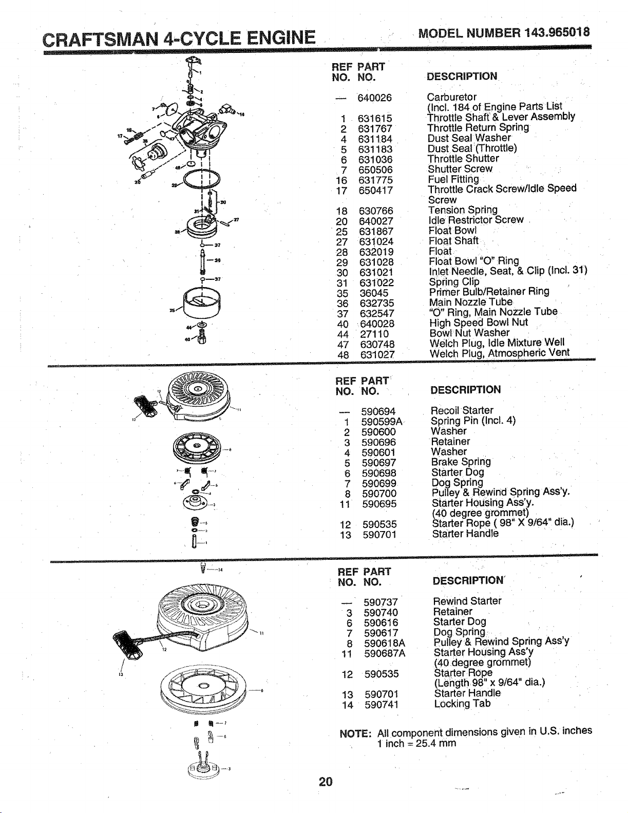
CRAFTSMAN 4=CYCLE ENGINE MODELNUMBER143.965018
f-'r,%
!
REF PART
NO, NO. DESCRIPTION
640026
1 631615
2 631767
4 631184
5 631183
6 631036
7 650506
16 631775
17 650417
!8 630766
20 640027
25 631867
27 631024
28 632019
29 631028
30 631021
31 631022
35 36045
36 632735
37 632547
40 640028
44 27110
47 630748
48 63'1027 Welch Plug, Atmospheric Vent,
........ ,,,, i '
Carburetor
(Incl. 184 of Engine Parts List
Throttle Shaft & Lever Assembly
Throttle Return Spring
Dust Seal Washer
Dust Seal (Throttle)
Throttle Shutter
Shutter Screw
Fuel Fitting
Throttle Crack Screw/Idle Speed
Screw
Tension Spring
idle Restrictor Screw
Float Bowl
Float Shaft
Float
Float Bowl "O" Ring
Inlet Needle, Seat, & Clip (incl. 31)
Spring Clip
Pdmer Bulb/Retainer Ring
Main Nozzle Tube
"O" Ring, Main Nozzle Tube
High Speed Bowl Nut
Bow! Nut Washer
Welch Plug, Idle Mixture Well
REF PART
NO. NO. DESCRIPTION
_--r_
590694
1 590599A
2 590600
3 590696
4 590601
5 590697
6 590698
7 590699
8 590700
11 590695
12 590535
13 590701
Recoil Starter
Spring Pin (!ncl. 4)
Washer
Retainer
Washer
Brake Spdng
Starter Dog
Dog Spring
Pulley & Rewind Spring ASs'y.
Starter Housing Ass'y.
(40 degree grommet)
Starter Rope ( 98" X 9/64" dia.)
Starter Handle
.... REF PART
NO. NO. DESCRIPTION
/
13
20
590737 Rewind Starter
3 590740 Retainer
6 590616 Starter Dog
7 590617 Dog Spring
8 590618A Pulley& Rewind Spring Ass'y
11 590687A Starter Housing Ass'y
(40degree grommet)
12 590535 Starter Rope .
(Leiigth 98" x 9/64 dia.)
13 590701 Starter Handle
14 590741 Locking Tab
NOTE: All component dimensions given in U.S, inches
1 inch = 25.4 mm
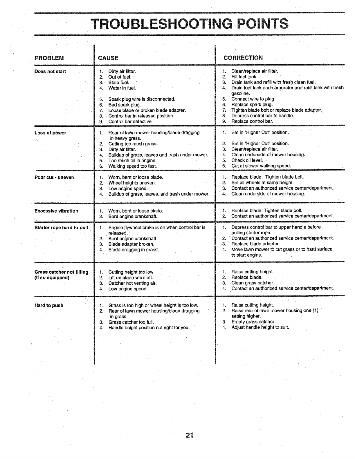
TROUBLESHOOTING POINTS
PROBLEM
Does not start
CAUSE
1, Dirty air filter.
2. Out of fuel.
3. Stale fuel.
4. Water infueL
5. Spark plug wire is disconnected,
6. Bad spark plug.
7, Loose blade or broken blade adapter.
8. Control bar in released position
9. Control bar defective
CORRECTION
I. Clean/replace air filter,
2. Fil! fueltank.
3. Drain tank and refill with fresh clean fuel.
4, Drain fuel tank and carburetor and refill tank with fresh
gasoline.
5. Connect wire to plug,
6. Replace spark plug.
7_ Tighten blade bolt or replace blade adapter,
8. Depress control bar to handle.
9. Replace control bar,
Loss of power
1, Rear of lawn mower housing!blade dragging
in heavy grass.
2, Cuttingtoo much grass.
3. Dirty air _ter,
4. Buildup of grass, leaves and trash under mower.
5. Too much oil in engine.
6. Walking speed toofast.
1, Set in "Higher Cut" position.
2. Set in "Higher Cut" position.
3. Clean/repfece air filter.
4. Clean underside of mower housing.
5. Check oil level.
6. Cut at slower walking speed.
Poor cut - uneven
. . _=
Excessive vibration
1, Worn, bent or loose blade.
2. Wheel heights uneven.
3. Low engine speed,
4_ Buildup of grass, leaves, and trash under mower.
1, Worn, bent or loose blade.
2, Bent engine crankshaft.
1. Replace blade. Tighten blade bolt.
2. Set all wheels at same height,
3. Contact an authorized service center/department,
4. Clean underside of mower housing,
1. Replace blade. Tighten blade bolt.
2. Contact an authorized service center/department,
Starter rope hard to pull 1. Engine flywheel brake is on when control bar is
released.
2. Bent engine crankshaft
3, Blade adapter broken.
4, Blade dragging in grass,
1. Depress control bar to upper handle before
pulling starter rope.
2. Contact an authorized service center/department.
3. Replace blade adapter.
4. Move lawn mower to cut grass or to hard surface
to start engine.
Grasscatcher not filling
(If so equipped)
Hard to push
1. Cutting height too low.
2, Lift on blade worn off,
3. Catcher not venting air.
4. Low engine speed.
1. Grass is too high or wheel height is too low.
2. Rear of lawn mower housing/blade dragging
in grass.
3. Grass catcher too full.
4. Handle height position not right for you.
1. Raise cutting heighL
2, Replace blade.
3. Clean grass catcher.
4. Contact an authorized service center/department,
1. Raise cutting height,
2. Raise rear of lawn mower housing one (1)
setting higher.
3. Empty grass catcher,
4. Adjust handle height to suit.
21
OWNER'S
MANUAL
MODEL NO.
917.386240
IF YOU NEED
REPAIR SERVICE
OR PARTS:
FOR REPAIR SERVICE, CALL
THIS TOLL FREE NUMBER:
1.800-4-REPAIR
(1-.800-473-7247)
FOR REPLACEMENT PARTS
INFORMATION AND
ORDERING, CALL THIS
TOLL FREE NUMBER"
1-800LFON-PART
(1-800_366=7278)
£RIIFTZMIIN °
5.0 HORSEPOWER
20" REAR DISCHARGE
ROTARY LAWN MOWER
Each lawn mower has its own model number. Each en-
gine has its own model number.
The model number for your lawn mower will be found on a
decat attached to the rear of the lawn mower housing.
The model number for your engine will be found on the
blower housing of the engine.
All parts listed herein may be ordered from any Sears,
Roebuck and Co. Service Center!Department and most _
Retail Stores.
WHEN ORDERING REPAIR PARTS, ALWAYS GIVE THE
FOLLOWING INFORMATION:
• PRODUCT- LAWN MOWER
• MODEL NUMBER - 917.386240
,, ENGINE - CRAFTSMAN - MODEL NO. 143o965018
,, PART NUMBER
° PART DESCRIPTION
Your Sears merchandise has added value 'when you
consider Sears has service units nationwide staffed with
Sears trained technicians .... professional technicians
specifically trained to insure that we meet our pledge to.
you, we service what we sell.
22
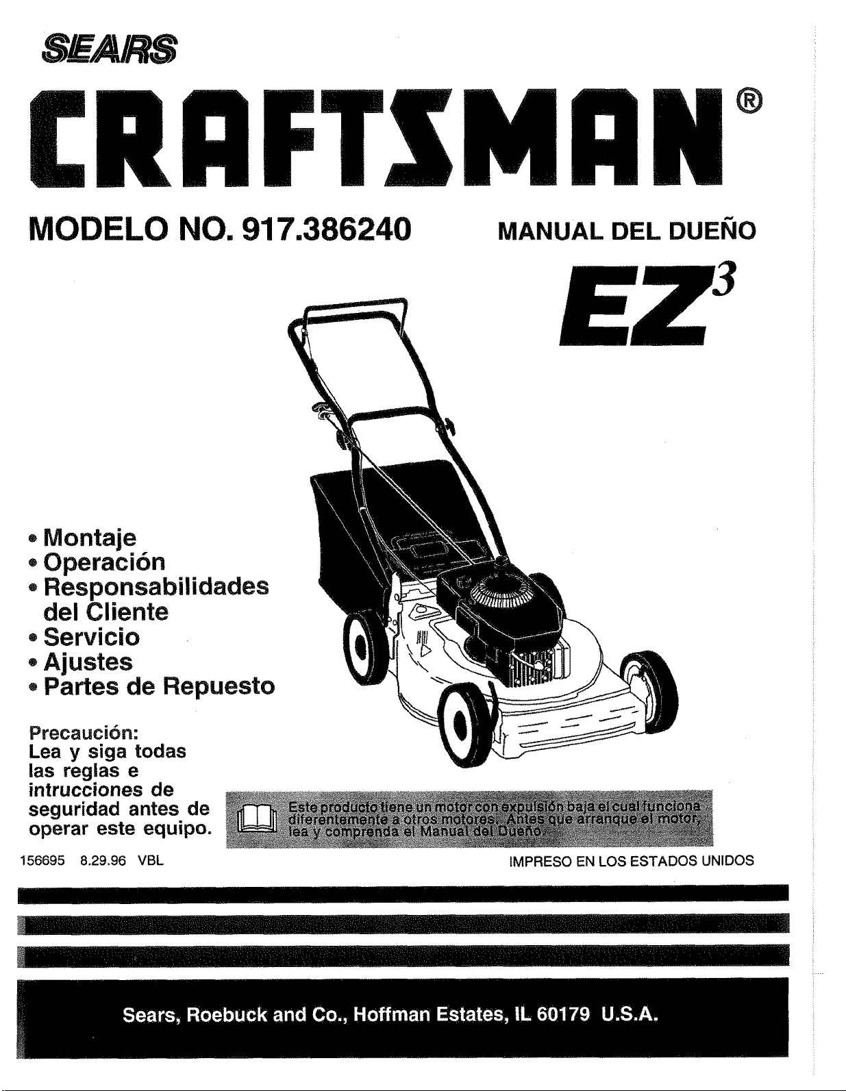
®
MODELO NO. 917.386240 MANUAL DEL DUEI_IO
• Montaje
Operacibn
+ Responsabilidades
del Cliente
+Servicio
+Ajustes
+Partes de Repuesto
Precauci6n:
Lea y siga todas
las reglas e
intrucciones de
seguridad antes de
operar este equipo.
!56695 8.29.96 VBL
tMPRESO EN LOS ESTADOS UNIDOS
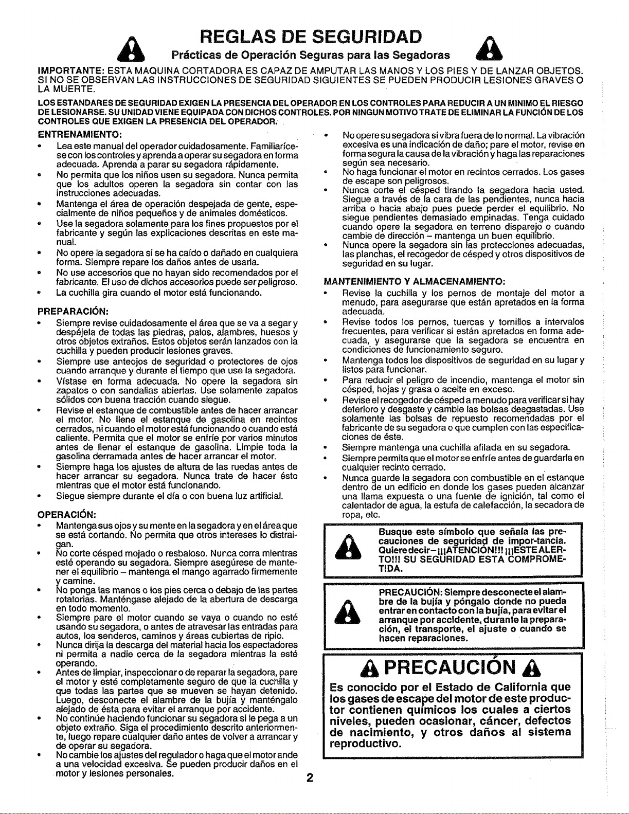
REGLAS DE SEGURIDAD
Prdcticas de Operaci6n Seguras para las Segadoras
IMPORTANTE: ESTA MAQUINA CORTADORA ES CAPAZ DE AMPUTAR LAS MANOS Y LOS PIES Y DE LANZAR OBJETOS.
SI NO SEOBSERVAN LAS INSTRUCCIONES DE SEGURtDAD SIGUIENTES SE PUEDEN PRODUCIR LESIONES GRAVES O
LA MUERTE,
LOS ESTANDARES DESEGURIDAD EXIGENLA PRESENClA DELOPERADOR EN LOSCONTROLIESPARA REDUCIR A UN MINIMO ELRIESGO
DE LESIONARSE.SU UNIDADVIENE EQUIPADACON DlCHOS CONTROLES. PORNINGUN MOTIVOTRATE DEELIMINAR LA FUNCK_NDELOS
CONTROLES QUE EX|GEN LA PRESENCIA DEL OPERADOR;
ENTRENAMIENTO:
• Lea este manual del operador cuidadosamente. FamUiarfce-
se con loscontrofes y aprenda a operar su segadora en forma
adecuada. Aprenda a parar su segadora r_,pidamente.
- No permita que los niSos usen su segadora. Nunca permita
que los adultos operen la segadora sin contar con las
instrucciones adecuadas.
• Mantenga el &rea de operaci6n despejada de gente, espe-
cialmente de niSos peque_,os y de animales dom_sticos.
o Use la segadora sotamente para los fines propuestos pot el
fabricante y seg0n las explicaciones descritas en este ma-
nual.
• No opere ta segadora si se ha cafdo o daSado en cualquiera
forma. Siempre repare los daSos antes de usarla.
• No use accesorios que no hayan sido recomendados por ei
fabricante. El uso de dichos accesodos puede set peligroso.
• La cuchilla gira cuando el motor est& funcionando.
PREPARACJC)N:
• Siempre revise cuidadosamente el drea que se va a segar y
desp_jela de todas las piedras, palos, alambres, huesos y
otros objetos extraP,os. Estos objetos ser._n lanzados con ta
cuchUlay pueden producir tesiones graves.
- Siempre use anteojos de seguridad o protectores de ojos
cuando arranque y durante e/tiempo que use la segadora.
• Vfstase en forma adecuada. No opere la segadora sin
zapatos o con sandalias abiertas. Use solamente zapatos
s61idos con buena tracci6n cuando siegue.
• Revise el estanque de combustible antes de hacer arrancar
el motor. No Ilene et estanque de gasolina en recintos
cerrados, nicuando el motor est,, funcionando o cuando est&
caliente. Permita que el motor se enffie por varios minutos
antes de Ilenar el estanque de gasolina. Limpie toda ia
gasolina derramada antes de hacer arrancar el motor.
Siempre haga los ajustes de altura de fas ruedas antes de
hacer arrancar su segadora. Nunca trate de hacer (_sto
mientras que el motor est& funcionando.
• Siegue siempre durante el dfa o con buena luz artificial.
OPERAC!6N:
° Mantenga sus ojosysu mente en tasegadora yen el _reaque
se est& cortando. No permita que otros intereses Io distrai-
gan.
• No corte c_sped rnojado o resbaioso. Nunca corra mientras
est_ operando su segadora. Siempre asegerese de mante-
her el ,equilibrio- mantenga et mango agarrado firmemente
ycamme.
• No ponga las manos o los pies cerca o debajo de tas partes
rotatodas. Mant6ngase alejado de ta abertura de descarga
en todo momento.
° Siempre pare el motor cuando se vaya o cuando no est6
usando su segadora, o antes de atravesar las entradas para
autos, los senderos, caminos y _.reas cubiertas de ripio.
Nunca dirija ia descarga del material hacia los espectadores
ni permita a nadie cerca de la segadora mientras ta est_
operando. , ,
• Antes de timpiar, inspeccionar o de reparar la segaaora, pare
el motor y est_ completamente seguro de que la cuchilla y
que todas las partes que se mueven se hayan detenido.
Luego, desconecte el alambre de la bujia y mant_ngalo
alejado de esta para evitar el arranque pot accidente.
• No continSe haciendo funcionar su segadora si le pega a un
objeto extraP,o. Siga el procedimiento descrito anteriormen-
te, luego repare cualquier daSo antes de volver a arrancar y
de operar su segadora. J
• No cambie los ajustes del regufador o haga que el motor ande
a una velocidad excesiva. Se pueden producir daSos en el
motor y lesiones personates.
• No opere su segadora si vibra fuera de Io normal. La vibraci6n
excesiva es una indicaci6n de daSo; pare el motor, revise en
forma segura la causa de lavibraci6n y haga las reparaciones
seg0n sea necesario.
° No haga funcionar eJmotor en recintos cerrados. Los gases
de escape son peligrosos,
• Nunca corte el c_sped tirando la segadora hacia usted.
Siegue a trav6s de la cara de ias pendientes, nunca hacia
arriba o hacia abajo pues puede perder et equilibrio. No
siegue pendientes demasiado empinadas. Tenga cuidado
cuando opere la segadora en terreno disparejo o cuando
cambie de direcci6n - mantenga un buen equilibrio.
• Nunca opere la segadora sin las protecciones adecuadas,
las planchas, el recogedor de c6sped y otros dispositivos de
seguridad en su lugar.
MANTENIMIENTO Y ALMACENAMIENTO:
• Revise la cuchilla y los pernos do montaje del motor a
menudo, para asegurarse que est_n apretados en la forma
adecuada.
• Revise todos los pernos, tuercas y tornillos a intervalos
frecuentes, para verificar si est&n apretaclos en forma ade-
cuada, y asegurarse que la segadora se encuentra en
condiciones de funcionamiento seguro.
• Mantenga todos los dispositivos de seguridad en su lugar y
listos para funcionar.
° Para reducir el peligro de incendio, mantenga el motor sin
c6sped, hojas y grasa o aceite en exceso.
° Revise el recogedor de c_sped a menudo para verificar si hay
deterioro y desgaste y cambie las bolsas desgastadas. Use
solamente las bolsas de repuesto recomendadas per ei
fabricante de su segadora o que cumpten con las especifica_
clones de _ste.
° Siempre mantenga una cuchilla afilada en su segadora.
° Siempre permita que el motor se enfrfe antes de guardarla en
cualquier recinto cerrado.
• Nunca guarde la segadora con combustible en el estanque
dentro de un edificio en donde Iosgases pueden aicanzar
una llama expuesta o una fuente de ignici6n, tal como el
calentador de agua, la estufa de calefacci6n, la secadora de
ropa, etc.
: i i ..... ',lrllr,
Busque este sfmbolo que se_ala ias pre-
caucmnes de seguridad de impor-tancia.
Quieredecir-i|iATENClON H! iiIESTE ALER-
TO!!! SU SEGURIDAD ESTA COMPROME-
TIDA.
"HILl:H
PRECAUCI6N: Siempre desconecte el alam-
bre de la bujfa y p6ngaio donde no pueda
entrar en contacto con la buj(a, para evitar el
arranque por accidente, durante la prepara-
ci6n, el transporte, el ajuste o cuando se
hacen reparaciones.
III
............ iiiiiii _1,!1 _ _ I "11'1]'1
A PRECAUCION A
Es conocido pot el Estado de California que
los gases de escape del motor de este produc-
tor contienen qmmicos los cuales a ciertos
niveles, pueden ocasionar, cdncer, defectos
de nacimiento, y otros daSos al sistema
reproductivo.
2
FELICiTACIONES per lacompra de su segadoraSears Craftsman.
Ha side d}seSada, planificada y fabricada para darle la meier
confiabilidad y el meier rendimiento posibles.
En el case de que se encuentre con cualquier problema que no
pueda sofucionar facilmente, haga e.Ifavor de ponerse en contac-
tocon su Centro/Departamento de Servicio Sears m_s cercano.
Sears cuenta con t6cnicos bien capacitados y competentes y con
las herramientas adecuadas para darle servicio o para reparar su
unidad.
Haga el favor de leery de guardar este manual. Estas instruccio-
nes le permitir&n montar y mantener su segadora en forma
adecuada. Siempre observe las "REGLAS DE SEGURIDAD,"
NUMERO DE
MODELO
NOMERO DE
SERIE
9!7,386240
FECHA DE
COMPRA
EL_NOMERO DEL MODELO Y EL DE SERtE SE ENCUEN-
TRAN EN LA CALCOMANIA ADJUNTA A LA PARTE TRA-
SERA DE LA CAJA DE LA SEGADORA.
DEBE REGISTRAR TANTO EL NUMERO DE SERIE COMe
LA FECHA DE COMPRA Y MANTENGALOS EN UN LU-
GAR SEGURO PARA REFERENCIA EN EL FUTURe.
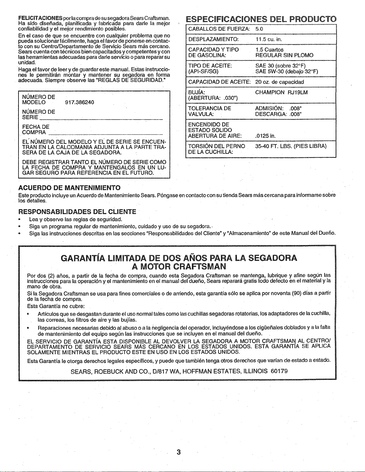
ESPECIFtCACiONES DEL PRODUCTO
CABALLOS DE FUERZA: 5.0
DESPLAZAMIENTO: 11.5 cu. in_
CAPACtDAD Y TIPO ! .5 Cuartos
DE GASOLINA: REGULAR SIN PLOMO
TIPO DE ACEITE: SAE 30 (sobre 32°F)
(API-SF/SG) SAE 5W-30 (debajo32°F)
CAPAClDAD DE ACEITE: 20 oz. de capacidad
BUJiA: CHAMPION RJ19LM
(ABERTURA: .030")
TOLERANCIA DE ADMISI6N: ,008"
VALVULA: DESCARGA: .008"
ENCENDIDO DE
ESTADO SOLIDO
ABERTURA DE AIRE: .0125 in.
TORSION DEL PERNO 35,40 FT. LBS. (PIES LIBRA)
DE LA CUCHILLA:
ACUERDO DE MANTENllVIIENTO
Este producto incluye un Acuerdo de Mantenimiento Sears. P6ngase en contacto con su tienda Sears m_s cercana para informarse sobre
los detatles,
RESPONSAB|LIDADES DEL CLIENTE
• Lea y observe las reglas de seguridad.
° Siga un programa regular de mantenimiento, cuidado y use de su segadora._
Siga las instrucciones descritas en las seCciones "Responsabilidades del Cliente" y "Almacenamiento" de este Manual del Duer3o.
GARANT{A LIMITADA DE DOS ANOS PARA LA SEGADORA
A MOTOR CRAFTSMAN
Per des (2) aP,os, a partir de la fecha de compra, cuando esta Segadora craftsman se mantenga, lubrique y afine seg0n las
instrucciones para la operaci6n y el mantenimiento en el manual del dueSo, Sears reparara" gratis todo defecto en el material y la
mane de obra.
Si la Segadora Craftsman se usa para fines comerciales o de arriendo, esta garantfa s6!o se aplica per noventa (90) dfas a partir
de la fecha de compra.
Esta Garant_a no cubre:
• Articulos que se desgastan durante el use norma! tarescome tas cuchillas segadoras rotator_as, los adaptadores de la cuchilla,
las correas, los filtros de aire y las buj{as.
= Reparaciones necesarias debido a! abuse o a la negligencia del operador; incluy6ndose a los cig0eSales doblados y a ta falta
de mantenimiento del equipo segen las instrucciones que se incluyen en el.manual del dueSo.
EL SERVICIO DE GARANTfA ESTA DtSPONtBLE AL DEVOLVER LA SEGADORA A MOTOR CRAFTSMAN AL CENTRe/
DEPARTAMENTO DE SERVlCIO SEARS MAS CERCANO EN LOS ESTADOS UNtDOS. ESTA GARANT{A SE APLICA
SOLAMENTE MIENTRAS EL PRODUCTO ESTE EN use EN LOS ESTADOS UNIDOS.
Esta Garantt'a le otorga derechos lega es especfficos, y puede que tambi_n tenga otros derechos que varfan de estado a estado.
SEARS, ROEBUCK AND CO., D/817 WA, HOFFMAN ESTATES, ILLINOIS 60179
3
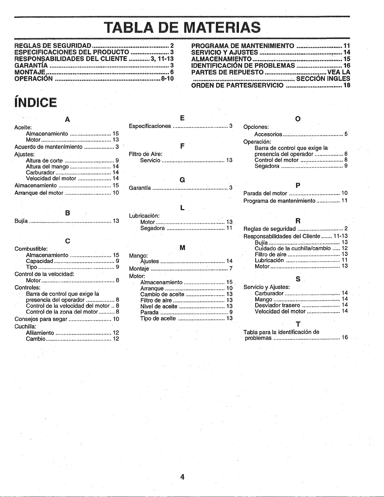
TABLA
REGLAS DE SEGURIDAD ............................................ 2
ESPECJFICACIONES DEL PRODUCTO ...................... 3
RESPONSABILIDADES DEL CLiENTE ............ 3, 11-13
GARANTiA .................................................................... 3
MONTAJE ....................................................................... 6
OPERACION ............................................................ 8-10
PROGRAMA DE MANTENJMIENTO .......................... 11
SERViCIO Y AJUSTES ............................................... 14
ALMACENAMIENTO .......................... ......................... 15
IDENTIFICACI6N DE PROBLEMAS ........................ .. 16
PARTES DE REPUESTO ................................... VEA LA
........................................................ .. SECCION iNGLES
ORDEN DE PARTES/SERVICIO ................................ 18
iNDICE
A
Aceite:
Almacenamiento .......................... 15
Motor ......................... ;....... :.......... 13
Acuerd0 de mantenimiento ................... 3
Ajustes:
Altura de corte ............................... 9
Altura del mango .......................... 14
Carburador,.._ ............................... 14
Velocidad del motor ..................... 14
Aimacenamiento ................................. 15
Arranque del motor ............................. 10
B
Buj[a .................................................... 13
C
Combustible:
Almacenamiento .......................... 15
Capacidad ....................................... 9
Tipo ................................................ 9
Control de la velocidad:
Motor .............................................. 8
Controles:
Barra de control que exige la
presencia del operador .................. 8
Control de la velocidad del motor .. 8
Control de la zona del motor .......... 8
Consejos para segar ........................... 10
Cuchilla:
Afilamiento ................................... 12
Cambio ......................................... 12
E
Especificaciones ................................... 3
F
Filtro de Aim:
Servicio ........................................ 13
G
Garantia ................................................ 3
L
Lubricaci6n:
Motor ............................................ 13
Segadora ..................................... 11
M
Mango:
Ajustes ......................................... 14
Montaje ................................................. 7
Motor:
Almacenamiento .......................... 15
Arranque ....................................... 10
Cambio de aceite ......................... 13
Filtro de aire ................................. 13
Nivel de aceite. ............................ 13
Parada ........................................... 9
Tipo de aceite .............................. 13
O
Opciones:
Accesorios.,.,; ................................. 5
Operaci6n:
Barra de control que exige la
presencia del operador .................. 8
Control del motor ............................ 8
Segadora ....................................... 9
P
Parada dei motor ................................ 10
Programa de mantenimiento ............... 11
R
Reglas de seguridad ............................. 2
Responsabilidades del Cliente ....... 11-13
Buj_a ............................................. 13
Cuidado de ta cuchitla/cambio ..... 12
Filtro de aire ................................. -13
LubricaciSn .................................. 11
Motor ............................................ 13
S
Servicio y Ajustes:
Carburador ................................... 14
Mango ......:................................... 14
Desviador trasero ........................ 14
Velocidad del motor ..................... !4
T
Tabla para la identificaci6n de
problemas .......................................... 16
4
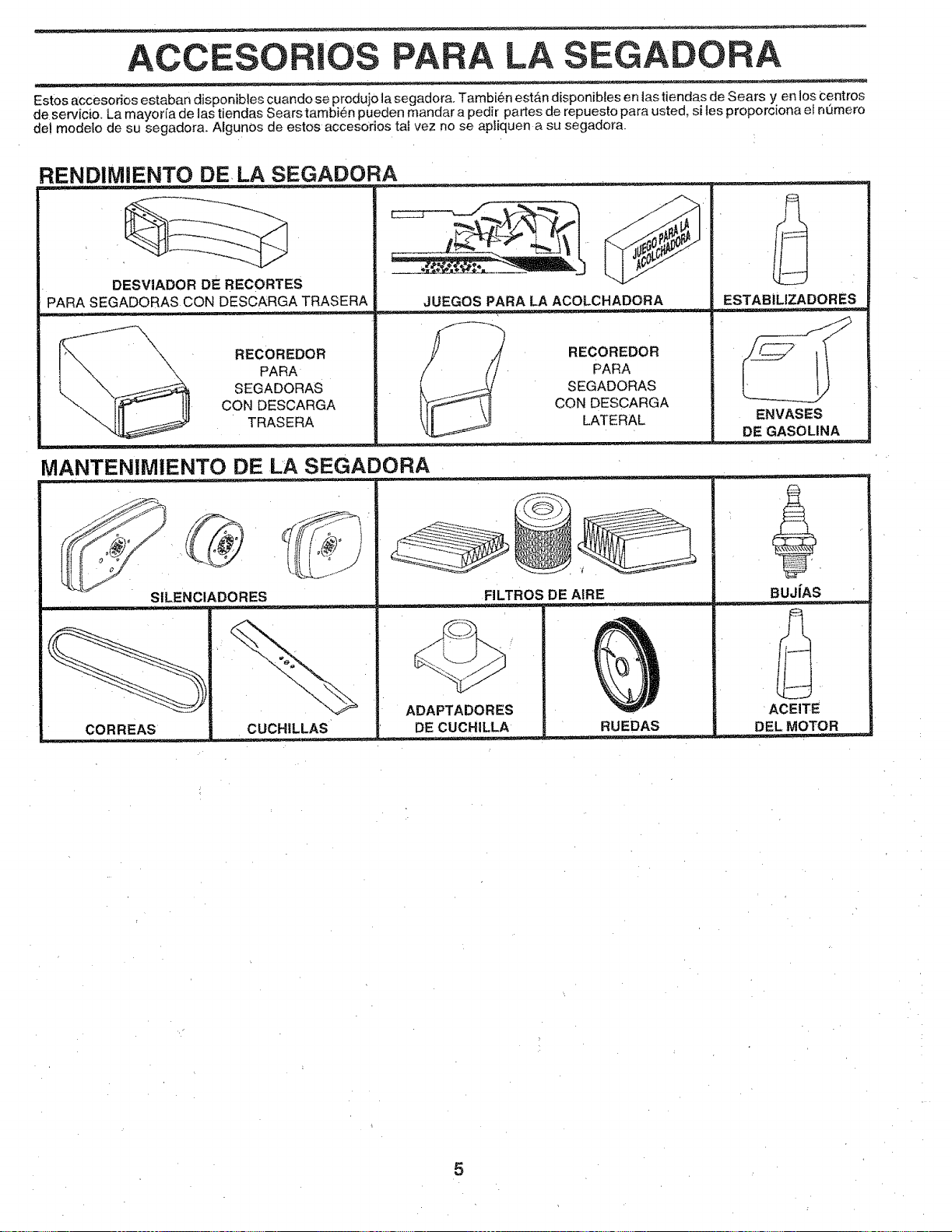
ACCESORIOS PARA LA SEGADORA
Estos accesorios estaban disponibles cuando se produjo ta segadora. Tambi6n est&n disponibles en las tiendas de Sears yen los Centros
de servicio. La mayorfa de las tiendas Sears tambi_n pueden mandar a pedir partes de repuesto para usted, sites proporclona el numero
del modelo de su segadora. Algunos de estos accesorios taf vez no se apliquen a su segadora.
RENDIMIENTO DE LA SEGADORA
DESVIADOR DE RECORTES
PARA SEGADORASCON DESCARGA TRASERA
RECOREDOR
PARA
SEGADORAS
CON DESCARGA
TRASERA
JUEGOS PARA LA ACOLCH=ADORA
RECOREDOR
PARA
SEGADORAS
CON DESCARGA
LATERAL
MANTENIMtENTO DE LA SEGADORA
ESTABiLIZADORES
ENVASES
DEGASOLINA
FILTROS DE AIRE
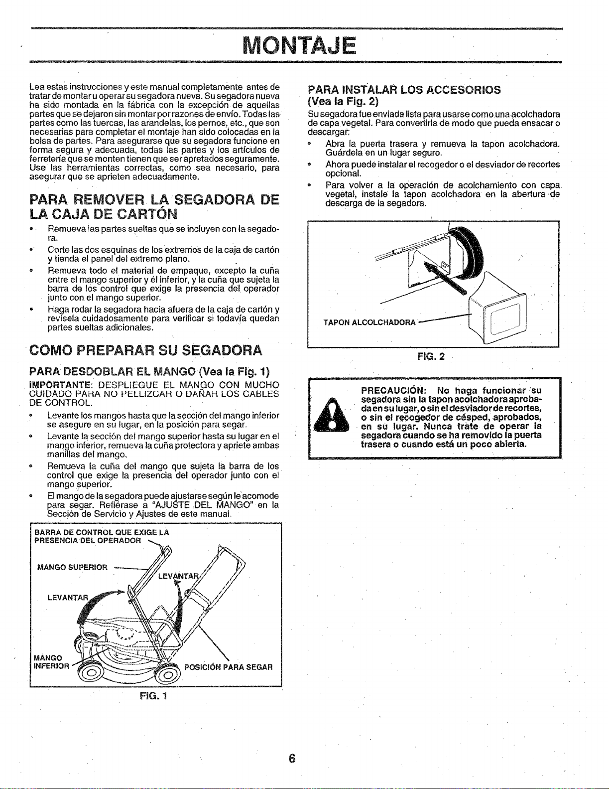
TAJE
Lea estas instrucciones yeste manual completamente antes de
tratar de montar u operar su segadora nueva. Su segadora nueva
ha sido montada en la fabdca con la excepcion de aquellas
partes que se dejaron sin montar por razones de envfo. Todas INS
partes como INs tuercas, INSarandelas, los pernos, etc., que son
necesarias para comptetar e! montaje han sido co!ocadas en la
bolsa de partes. Para asegurarse que su segadora funcione en
forma segura y adecuada, todas INS partes y 10s art(culos de
ferreteda que se monten tienen que ser apretados seguramente.
Use INS herramientas correctas, como sea necesario, para
asegurar que se aprieten adecuadamente.
PARA REMOVER LA SEGADORA DE
LA CAJA DE CARTON
- Remueva iNSpartes sueltas que se incluyen con ta segado-
ra.
, Corte INsdos esquinas de los extremos de Ia caja de cartdn
y tienda el panel del extremo piano.
Remueva todo et material de empaque, excepto la cuSa
entre el mango superior y el inferior, y la cuSa que sujeta la
barra de 10scontro! que exige (a presencia del operador
junto con el mango superior.
, Haga rodar la segadora hacia afuera de la eaja de cart6n y
rew'sela cuidadosamente para verificar si todavia quedan
partes sueltas adicionates.
COMO PREPARAR SU SEGADORA
PARA DESDOBLAR EL MANGO (Yea la Fig, 1)
(MPORTANTE: DESPLIEGUE EL MANGO CON MUCHO
CUIDADO PARA NO PELLlZCAR O DANAR LOS CABLES
DE CONTROL.
Levante los mangos hasta que la secci6n det mango inferior
se asegure en su lugar, en la posici6n para segar.
Levante la secci6n de( mango superior hasta su lugar en el
mango inferior, remueva la cuRa protectora y apriete ambas
manillas del mango,
- Remueva la cuSa del mango que sujeta ta barra de los
contro! que exige la presencla del operador junto con el
mango superior.
, Elmango de la segadora puede ajustarse seg0n le acomode
para segar. Refi#rase a "AJUSTE DEL MANGO" en la
Secci6n de Servicio y Ajustes de este manual.
BARRA DE CONTROL QUE EXIGE LA
PRESENCIADELOPERADOR ,._
/
////LEV_NTARi/ W
LEVANTAR /f _S
MANGO,, _.,-;;: ,. \
INFERIOR _ _ POSICI6N PARA SEGAR
FIG, 1
PARA iNSTALAR LOS ACCESORIOS
(Yea la Fig. 2)
Su segadora rue enviada lista para usarse Como una acolchadora
de capa vegetal. Para convert!riM de modo que pueda ensacar o
descargar:
- Abra la puerta trasera y remueva la tapon acolchadora.
Guardela en un lugar seguro.
= Ahora puede instalar el recogedor o el desviador de recortes
opcional,
- Para volver a la operaciSn de acolchamiento con capa
vegetal, instale la tapon acolchadora en la abertura .de
descarga de la segadora°
TAPON ALCOLCHADORA
FIG. 2
PRECAUCi(3N: No haga funcionar su
segadora sin la tapon aco|chadera aproba-
da en su iugar_ o sin el desviadorde recortes,
o sin el recegedor de cdsped, aprobados,
en su lugar. Nunca trate de operar ia
segadora cuando se ha removide la puerta
trasera o cuando estd un poco abierta.
6
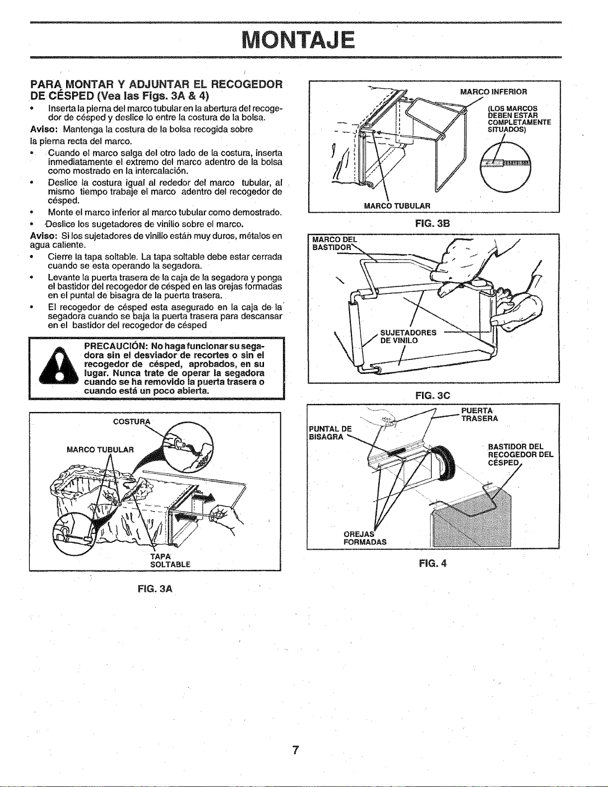
ONTAJE
PARA MONTAR Y ADJUNTAR EL RECOGEDOR
DE CESPED (Yea las Figs. 3A & 4)
• Inserta la pierna det marco tubular en la abertura del recoge-
dor de c6sped y destice 1oentre la costura de la boTsa.
Aviso: Mantenga la costura de la bolsa recogida sobre
ia pierna recta del marco.
• Cuando e] marco salga del 0tro lado de la costura, inserta
inmediatamente el extremo del marco adentro de la bolsa
como mostrado en la intercalacibn.
• Deslice la costura igual al rededor det marco tubular, al
mismo tiempo trabaje el marco adentro del recogedor de
cesped.
= Monte el marco inferior al marco tubular como demostrado.
Oeslice los sugetadores de vinilio sobre el marco,
Aviso: Si los sujetadores de viniiio est&h muy duros, m_talos en
agua caliente.
° Cierre la tapa softable° La tapa soltabie debe estar cerrada
cuando se esta operando la segadora.
• Levante la puerta trasera de la caja de la segadora y ponga
el bastidor del recogedor de cesped en tas orejas formadas
en el punta] de bisagra de la puerta traSera,
° El recogedor de c_sped esta asegurado en la caja de ta
segadora cuando se baja la puerta trasera para descansar
en el bastidor del recogedor de c_sped
_ RECAUC1ON:No haga funcionar su sega-
dora sin el desviadorde recortes o sin el
recogedor de cesped, aprobados, en su
lugar. Nunca trate de operar la segadora
cuando se ha rernovido la puerta trasera o
cuando est_ un poco abierta.
R_CO INFERIOR
(LOS MARCOS
DEBEN ESTAR
COMPLETAMENTE
SITUADOS)
,/r/
MARCO TUBULAR
FiG. 3B
MARCO DEL
\
FIG. 30
MARCO TUBULAR
TAPA
SOLTABLE
PUNTAL DE
BISAGRA
BAS_DOR DEL
RECOGEDOR DEL
CESPED
OREJA_
FORMADAS
FiG. 4
FIG. 3A
7
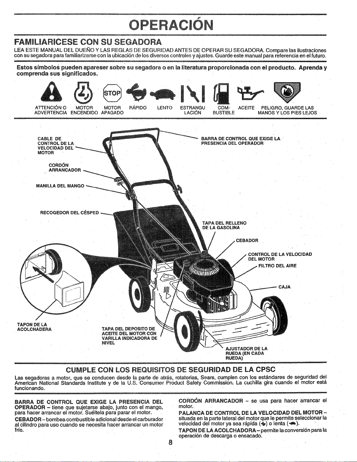
OPERAC
FAMILIARICESE CON SU SEGADORA
LEA ESTE MANUAL DEL DUEllO Y LAS REGLAS DE SEGURIDAD ANTES DE OPERAR SU SEGADORA= Compare las ilustraciones
con su segadora para familiarizarse con la ubicaci6n de los diversos centroles y ajustes. Guarde este manual para referencia en el future.
Estos sirnbolos pueden apateser sobre su segadora o en _a Riteratura propercionada con et producto. Aprenda y
cornprenda sus significados.
ATTENCI(_)N O COM-
ADVERTENCIA BUSTiBLE
MOTOR MOTOR R,_,PIDO t.ENTO ESTRANGU
ENCENDIDO APAGADO LACION
ACEITE PEL1GRO,GUARDE LAS
MANES Y LOS PIES LEJOS
CABLE DE
CONTROL DE LA
VELOCIDAD DEL
MOTOR
CORDON
ARRANCADOR
BARRA DE CONTROL QUE EXiGELA
PRESENCIA DEL OPERADOR
MAN|LLA DEL
RECOGEDOR DEL C_SPED
TAPA DEL RELLENO
DE LAGASOLINA
CONTROL DE LA VELOCIDAD
DEL MOTOR
DEL AIRE
CAJA
TAPON DE LA --_'_J
ACOLCHADERA TAPA DEL DEPOSITO DE _
ACEITE DEL MOTOR CON
VAR1LLA INDICADORA DE
NIVEL
AJUSTADOR DE LA
RUEDA(ENCADA
RUEDA)
CUNIPLE CON LOS REQUISITES DE SEGURtDAD DE LA CPSC
Las segadoras a motor, que se conducen desde ia parte de atr&s, rotatorias, Sears, cumplen con los estdndares de seguridad de/
American National Standards institute y de {a U.S. Consumer Product Safety Commission. La cuchilEa gira cuando el motor estd
funcionando.
BARRA DE CONTROL QUE EX1GE LA PRESENCIA DEL
OPERADOR - tiene que sujetarse abajo, junto con el mango,
para hacer arrancar el motor. Su_ltela para parar el motor.
CEBADOR- bombea combustible adiciona_ desde ef carburador
al cilindro para use cuando se necesita hacer arrancar un motor
frlo.
8
CORD6N ARRANCADOR - se usa para hacer arrancar et
motor.
PALANCA DE CONTROL DE LA VELOCIDAD DEL MOTOR -
situada en la parte lateral del motor que le perrnite seleccionar la
velocidad del motor ya sea r_pida (,_) o lenta (.€_),
TAPON DE LA ACOLCHADORA- permite la conversibn para la
operaci6n de descarga o ensacado.
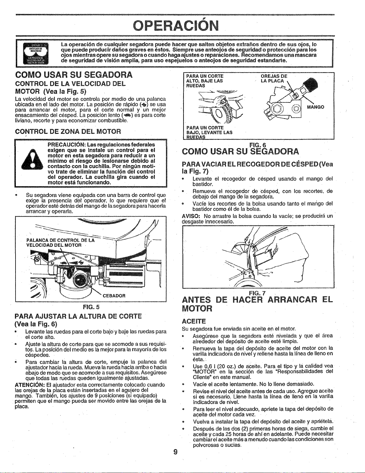
f
OPERACIO
COMO USAR SU SEGADORA
CONTROL DE LA VELOCIDAD DEL
MOTOR (Vea la Fig. 5)
La velocidad del motor se controla por medio de una palanca
ubicada enel lado delmotor. La posici6n de r&pido (,_) se usa
para arrancar el motor, para el code normal y un mejor
ensacamiento del c_sped. La posiciSn lento (,_) es para corte
liviano, recorte y para economizar combustible.
CONTROL DE ZONA [:)EL MOTOR
! _e un control para el
| A A _dora para reduoir a un
| _ m_esgo de tesionarse debido al
| _ contacto __g_n moti-
-- _rate de eliminar la funci6n del control
del operad_chilla gira cuando et
' motor est_ funcionando.
Su segadora viene equipada con una barra de control que
exige ia presencia det operador, !o quo requiere que et
operador est6 detr_s del mango de la segadora para hacerla
arrancar y operar_la.
PALANCA DE CONTROL DE LA
VELOCIDAD DEL MOTOR ,
FiG. 5
PARA AJUSTAR LA ALTURA DE CORTE
(Vea la Fig. 6)
• Levante las ruedas para el corte bajoy baje las ruedas para
el corte alto.
= Ajuste ta altura de corte para que se acomode a sus requisi-
tos_La posiciSn del medio os fa mejor para la mayoria de los
cdspedes.
Para cambiar la altura de corte, empuje ta palanca det
ajustador hacia la rueda. Mueva la rueda hacia ardba o hacia
abaj0 de modo que se acomode a sus requisitos, AsegQrese
que todas las ruedas queden igualmente ajustadas.
ATENCI6N: El ajustador esta correctamente colocado cuando
tas orejas de la placa est&n insedadas en el agujero del
mango. Tambien, los ajustes de 9 posiciones (si equipado)
permiten que el mango pueda set movido entre las orejas de la
placa.
9
PARA l.IN CORTE OREJAS DE
ALTO, BAJE LAS LA
RUEDAS
PARA UN CORTE
BAJO, LEVANTE LAS
ED_'- -: ......
FIG. 6
COMO
MANGO
USAR SU SEGADORA
PARA VACIAR EL RECOGEDOR DE CESPED (Yea
la Fig. 7)
- Levante el recogedor de cesped usando e! mango dot
bastidor.
- Remueva et recogedor de C6sped, con los recortes, de
debajo de! mango de la segadora.
Vacfe los recortos de la bolsa usando tanto el mango del
bastidor como el de la bolsa.
AVISO: No arrastre la bolsa cuando la vacie; so producir_ un
desgaste innecosado.
FIG, 7
ANTES DE HACER ARRANCAR EL
tV!OTOR
ACEiTE
Su segadora rue enviada sin aceite en el motor.
= AsegSrese que la segadora est_ niveiada y que el _rea
alrededor del depSsito do aceite est_ |impia.
• Remueva ia tapa del dep6sito de aceite del motor con la
varilla indicadora de nivel y rellene hasta la l{nea de lleno en
6sta, '
. Use 0,6 i (20 oz.) de aceite. Para el tipo y la calidad vea
"MOTOR" en la secc|Sn de ias "Responsabilidades del
Ciiente" en este manual.
- Vacie el aceite lentamente. No to Ilene demasiado,
, Revise el nivel del aceite antes de cada uso. Agregue aceite
si es necesario: Llene hasta la l{nea de lleno en la varilla
indicadora de niveL
= Para leer el nivel adecuado, apriete la tapa del depbsito de
aceite del motor cada vez.
Vuelva a instalar la tapa del depbsito del aceite y apri6tela.
, Despu_s de las dos (2) primeras horas de siega, cambie el
aceite y cada 25 horas de ah{ en adelante. Puede necesitar
cambiar el aceite m&s a menudo cuando las condiciones son
poivorosas o sucias.
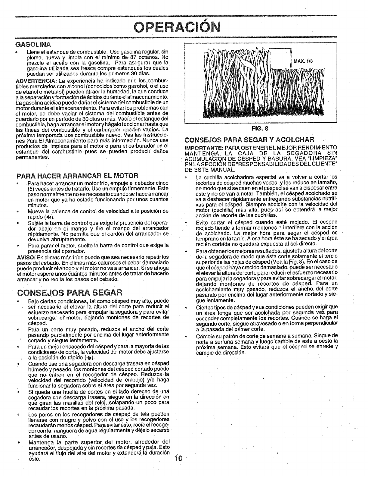
OPERAC|ON
GASOLINA
= Llene et estanque de combustible_ Use gasolina regular, sin
p!omo, nueva y limpia con et mfnirno de 87 octanos, No
mazda et aceite con la gasolina, Para asegurar que la
gasolina utilizada sea fresca compre estanques los cuale s
puedan ser utilizados durante los primeros 30 dfas+
ADVERTENCIA, La expedencia ha indicado que los .combus-
tibles mezclados con aicoho! (conocidos como gasohol, o el uso
de etanol o metanot) pueden atraer la humedad, la que conduce
a ta separaci6n y formaci6n de Acidos durante el almacenamiento.
La gasolina acfdica puede daffar e[ sistema del combustible de un
motor durante el almacenamiento. Para evitar los problemas con
el motor, se debe vaciar el sistema del combustible antes de
guardarlo por un peffodo de 30 dfas o mAs. Vacie el estanq ue del
combustible, haga arrancar el motory hagalo funCionar hasta qua
las lfneas del combustible y el carburador queden vac[os. La
pr6xima temporada use combustible nuevo. Vea [as lnstruccio-
nes Para El Almacenamiento para m,_s informaci6n. Nunca use
productos de limpieza para el motor o para el carburador en e[
estanque del combustible pues se pueden producir dafios
permanentes.
PARA HACER ARRANCAR EL MOTOR
• Para hacer arrancar un motor if[o, empuje el cebador cinco
(5) veces antes de tratado. Use un empuje firmemente. Este
paso normalmente no es necesario cuando se hacearrancar
un motor qua ya ha estado funcionando per unos cuantos
minutos.
• Mueva la palanca de control de velocidad a la posici6n de
rapido (_).
- Sujete la barra de control que exige la presencia del opera-
dor abajo en el mango y tire el mango del arrancador
rApidamente, No permita que el cord6n del arrancador se
devuelva abruptamenteo
• Para parar el motor, sueite ta barra de control que exige la
presencia de! operador.
AVISO: En ciimas mAs fffos puede que sea necesario repetir los
pasos del cebado. En climas mAs calurosos el cebar demasiado
puede producir el ahogo y e! motor no va a arrancar. Si se ahoga
el motor espere unos cuantos mi nutos antes de tratar de hacerlo
arrancar y no repita los pasos del cebado.
CONSEJOS PARA SEGAR
- Bajo ciertas condiciones, tal como cesped muy alto, puede
set necesario et elevar ia altura del corte para reducir el
esfuerzo necesario para empujar la segadora y para evitar
sobrecargar el motor, dejando montones de recortes de
c6sped.
- Para un corte muy pesado, reduzca el ancho del corte
pasand0 parcialmente pot encima del lugar anteriormente
cortado y siegue lentamente.
, Para un mejor ensacado del c6sped y para la mayorfa de las
condiciones de corte, [a velocidad del motor debe ajustarse
a la posici6n de r#,pido (_).
• Cuando use una segadora con descar_a trasera en c6sped
h_medo y pesado, los montones del cesped cortado puede
que no. entren en el recogedor de c6sped. Reduzca [a
ve!ocidad del recorddo (velocidad de empuje) y/o haga
funcionar la segadora sobre el Area per segunda vez.
• Si queda una huetla de cortes en el lado derecho de una
segadora Con descarga trasera, siegue en |a direcci6n en
que giran las maniUas del reloj, solapando un poco para
recaudar los recortes en la pr6xima pasada.
= Los poros en los recogedores de c_sped de teIa pueden
llenarse con mugre y polvo con et uso y los recogedores
recaudarAn menos c_sped. Para evitar 6sto, rocfe el recoge-
dot con ta manguera de agua regularmente y d6jelo secarse
antes de usarlo.
, Mantenge la parte superior del motor, alrededor del
arrancador, despejada y sin recortes de c6sped y paja. Esto
ayudar& el flujo del aire dei motor y extender& la duraci6n
_ste. 10
MAX. 1/3
FIG. 8
CONSEJOS PARA SEGAR Y ACOLCHAR
[MPORTANTE: PARAOBTENER EL MEJOR RENDIMIENTO
MANTENGA LA C AJA DE LA SEGADORA SIN
ACUMULACtQN DE CESPED Y BASURA. VEA "LIMPIEZA"
EN LA SECCtON DE =RESPONSABILIDADES DEL CLIENTE"
DE ESTE MANUAL.
- La cuchilla acolchadora especial va a volver a cortar los
recortes de c_sped rnuchas veces, y los reduce en tamafio,
de modo quesi se caen en el C_sped se van a dispesar entre
6ste y no se van a notar. Tambidn, el c6sped acolchado se
va a deshacer r&pidamente entregando substancias nutriti-
vas para e! c_sped. Siempre acotche con la velocidad del
motor (cuchilla) m&s alta, pues asi se obtendrA la mej0r
acci6n de recorte de las cuchi!las.
Evite cortar el cdsped cuando est_ mojado. E! c_sped
mojado tiende a formar mOntones e inteffiere con la accibn
de acolchado. La mejor hora para segar el c_sped es
temprano en la tarde. A esa hora _ste se ha secado y e! Area
reci_n cortada no quedarA expuesta al sol directo.
• Para obtener los mejores resuttados, ajuste [a altura del corte
de la segadora de modo qua _sta corte solamente el tercio
superior de tas hojas de c_sped (Yea [a Fig. 8). En el caso de
qua el c6sped haya crecido demasiado, puede set necesario
el elevar la altura del corte para reducir el esfuerzo necesado
para empujar la segadora y para evitar sobrecargar el motor,
dejando montones de recortes de c6sped. Para un
acolchamiento muy pesado, reduzca el ancho, det corte
pasando pot encima del lugar anteriormente cortado y sie-
gue |entarnente.
. Ciertos tipos de c_sped y sus condiciones pueden exigir que
un Area tenga qua ser acolchada pot segunda vez para
esconder completamente los recortes. Cuando se haga el
segundo corte, siegue atraVesado o en forma perpendicular
a la pasada del primer corte.
• Cambie su patr6n de corte de semana a semana. Siegue de
norte a sur_una sernana y lue_lo cambie de este a oeste la
pr6xirna seman& Esto evitara qua el cesped se enrede y
cambie de direcci6n.
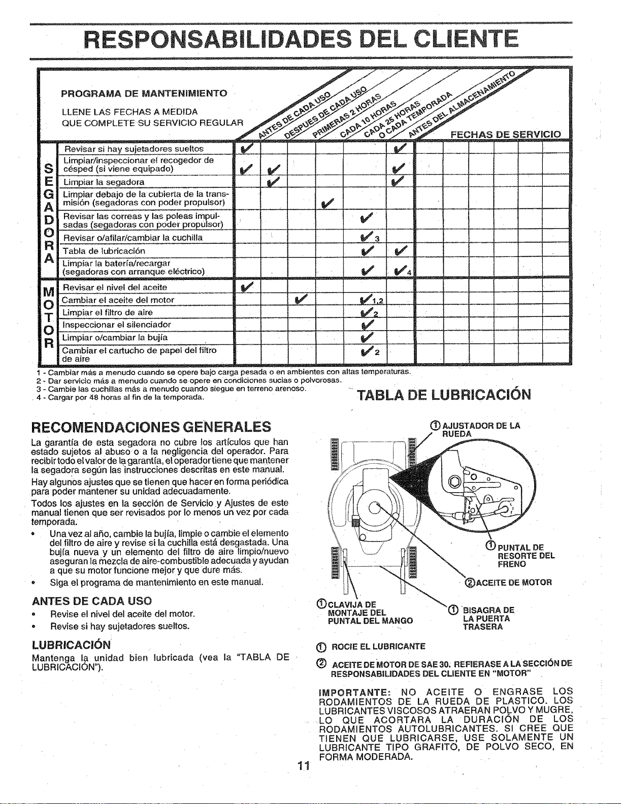
RESPONSA ILIDADES L CLIENTE
PROGRAMA DE MANTIENIMIENTO
LLENE LAS FECHAS A MEDPDA
QUE COMPLETE SU SERV|C10 REGULAR
FECHAS DE SERVlC_O
Revisar si hay sujetadores sueltos
Limpiaffinspeccionare! recogedor de
c_sped (si viene equipado)
Limpiar la segadora
Limpiar debajo de la cubierta de la trans-
misiSn (segadoras con poder proputsor)
Revisar 1as correas y las poleas imgul-
sadas (segadoras con poder propulsor) "
Revisar o/afilar/cambiar la cuchilla _'
Tab_a de lubricacf6n
Limpiar la baterfa/recargar
(segadoras con arr_nque.el6ctrico)
. . _ . ._ =_ =_=-- _-= = -= , . = _ _
Revisar el nivel del aceite
Cambiar el aceite del motor
Limpiar el filtro de ai[e ....
Inspeccionar el siienciador
Limpiar o!cambiar la bujia
Cambiar el cartucho de papel del filtro |
de aire .......... _
!
p
_3
.............v' V' ................ ••
V' v'4¸
J2
V'
- Cambiar mas a menude cuando se opere bajo carga pesada o en ambientes con altas temperaturas,
2 _ Dar servicio mas a menudo cuando se opere en condiciones sucias o potvorosas,
3 - Cambie las cuchJlfas m,_s a menudo cuando siegue en terreno arenoso. DE LUBRiCACION
4- Cargar pot 48 horas al fin de la temporada. TABLA
RECOMENDACiONES GEN ERALES
La garantfa de esta segadora no cubre los artfculos que han
estado sujetos al abuso o a la negligencia dei operador. Para
recibir todo et valor de la garant[a, el operador tiene que mantener
la segadora segen las instrucciones descritas en este manual.
Hay algunos ajustes que se tienen que hacer en forma periSdica
para poder mantener su unidad adecuadamente.
Todos los ajustes en la secci6n de Servicio y Ajustes de este
manual tienen que set revisados por Io rnenos un vez por cada
temporadao
• Una vez al a5o, cambie la bujfa, limpieo cambie el elemento
del filtro de aire y revise si la cuchiita estA desgastada. Una
bujia nueva y un elemen[o del filtro de aire limpio/nuevo
aseguran la mezcta de aireLcombustible adecuada y ayudan
a que su motor funcione meier y que dure mas.
• Siga et programa de manten_miento en este manual,
ANTES DE CADA USO
- Revise el nivel del aceite del motor.
- Revise si hay sujetadores sueltos.
LUBRlCAC|()N
Mantenga I# unidad bien lubricada
LUBRtCAClON").
(vea la "TABLA DE
(_) AJUSTADOR DE LA
RUEDA
11
(_PUNTALDE
RESORTE DEL
FRENO
(_)CLAV|JA DE 'C)BiSAGRA DE
MONTAJEDEL
PUNTALDEL MANGO LAPUERTA
.... TRASERA
(_ROC|EELLUBRICANTE
(_ ACE|TEDEMOTOR DESAE30;REFIERASEALASECCt_N DE
RESPONSABILIDADES DEL CL1ENTE EN"MOTOR"
IMPORTANTE: NO ACEITE 0 ENGRASE LOS
RODAMIENTOS DE LA RUEDA DE PLASTICO. LOS
LUBRICANTES VISCOSOS ATRAERAN POLVO Y MUGBE,
LO QUE ACORTARA LA DURACION DE LOS
RODAMtENTOS AUTOLUBRtCANTES. St CREE QUE
TIENEN QUE LUBRICARSE, USE SOLAMENTE UN
LUBRtCANTE TIPO GRAFITO, DE POLVO SECO, EN
FORMA MODERADA.
z
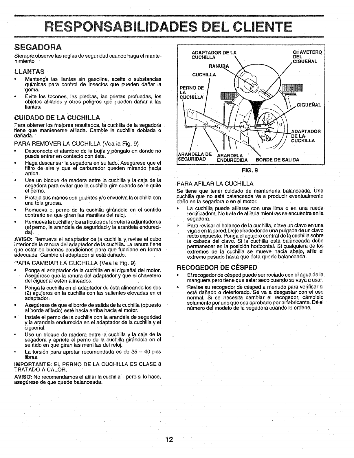
RESPONSABILIDA EL CLIENTE
SEGADORA
Siempre observe las reglas de seguridad cuando haga el mantes
nimiento, '
LLANTAS
= Manteng_a tas llantas sin cjasolina, aceite o substancias
qufrnicas para control de insectos que pueden dafiar la
goma.
- Evite los tocones, las piedras, las grietas profundas, los
objetos afilados y otros peligros que pueden dafiar alas
Ilantas.
CUIDADO DE LA CUCHILLA
Para obtener !os mejores resultados, la cuchilla de la segadora
tiene que mantenerse afilada. Cambie la cuchilfa doblada o
daSada.
PARA REMOVER LA CUCHILLA (Vea la Fig. 9)
Desconecte el aiambre de la buj{a y p6ngalo en donde no
pueda entrar en contacto con _sta.
Haga descansar la segadora en su lado. Asegerese que el
filtro de aire y que el carburador queden mkando hacia
arfiba.
Use un b!oque de madera entre la cuchilia y ta caja de ta
segadora para evitar que la cuchilla gire cuando se le quite
el perno.
• Proteja sus manos con guantes y/o envueiva la cuchiUa con
una tela gruesa.
• Remueva el perno de la cuchilla, gir&ndolo en el sentido
contrario en que giran las mani[las del reloj.
• Remueva la Cuchilla y los art{culos de ferreter{a adjuntadores
del pemo, la arandela de seguridad y la arandela endureci-
a).
AVISO: Remueva el adaptador de la cuchilla y revise el cubo
interior de la ranura del adaptador de la cuchi!la. La ranura tiene
que estar en buenas condiciones para que funcione en forma
adecuada. Cambie el adaptador si est=5dafiado.
PARA CAMBIAR LA CUCHILLA (Vea la Fig. 9)
- Ponga el adaptador de la cuchilla en el ciguefial del motor.
Aseg_rese que la ranura det adaptador y que el chavetero
del ciguefiat estbn alineados.
- Ponga la cuchilla en el adaptador de esta alineando los dos
(2) agujeros en la cuchiHa con tas salientes elevadas en el
adaptador.
Asegerese de que el borde de salida de la cuchi!la (opuesto
al borde afilado) este hacia arriba hacia el motor.
• Instale e! perno de la cuchilla con {a arandela de seguridad
y la arandela endurecida en et adaptador de la cuchilla y el
clguefial.
Use un bloque de madera entre la cuchilla y la caja de la
segadora y apriete et perno de la cuchilla gir&ndolo en el
sentido en que giran las manillas del reloj.
- La torsi6n para apretar recomendada es de 35 - 40 pies
tibras.
llVIPORTANTE: EL PERNO DE LA CUCHILLA ES CLASE 8
TRATADO A CALOR.
AV|SO: No recomendamos el afilar la cuchilla - pero si Io hace,
asegtJrese de que quede balanceada.
ADAPTADOR DE LA CHAVETERO
ARANDELA DE ARANDELA
SEGUR1DAD ENDURECIDA BORDE DE SALIDA
FIG. 9
PARA AFILAR LA CUCHILLA
Se tiene que tener cuidado de mantenerla balanceada. Una
cuchilla que no est_ balanceada Va a producir eventualmente
dafio en la segadora o en el motor.
• La cuchi|la puede a{ilarse con una. lima o en una rueda
rectificadora. No trate de affiarla mientras se encuentra en la
segadora:
Para revisar el balance de la cuchilla, clave un clavo enuna
viga o en la pared. Deje alrededor de una pulgada de un clave
recto expuesto, Ponga el agujero central dela Cuchilla sobre
la cabeza del clavo° Si la cuchilla est& balanceada debe
permanecer en la posici6n horizontal, Si cualquiera de los
extremos de a cuchilla se mueve hacia abajo, afiie el
extremo pesado hasta que 6sta quede balanceada.
RECOGEDOR DE ClaSPED
• El recogeder de cesped puede ser rociado con et agua de la
manguera pero tiene que estar seco cuando se vaya a usar.
o Revise su recogedor de c_sped a rnenudo para verificar si
estd daRado o deteriorado. Se va a desgastar con el uso
norma s se necesita cambiar el recogedor, cdmbielo
solamente por uno que sea aprobado por et fabricante. D6 el
ndmero del modelo de ta segadera cuando Io ordene.
12
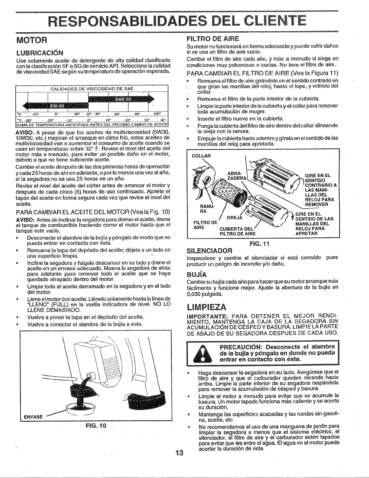
RESPONSA LI L CLIENTE
MOTOR FILTRO DE AIRE
LUBRICACION
Use solamente aceite de detergente de alta calidad clasificado
con la clasificaciSn SF o SG de servicio API+Se]eccione ta ca[|dad
de viscosidad SAE segtfn su temperatura de operacibn esperada.
OALIDADES DE VISCOSIDAD DE SAE
AVISO: A pesar de que los aceites de multiviscosidad (5W30,
10W30, etc,) mejoran el arranque en clima fifo, estos aceites de
multiviscosidad van a aumentar et consume de aceite cuando se
usan en temperaturas sobre 32 ° F. Revise el nivel del aceite del
motor mas a menudo, para evitar un posible daSo e_ el moto[,
debido a q ue no tiene suficiente aceite.
Cambie el aceite despues de las dos primeras horas de operaci6n
y cada 25 horas de ahf en adelante, o pot !o menos una vez al afio,
si la segadora no se usa 25 horas en un aSo.
Revise el nivei del aceite det carter antes de arrancar el motor y
despu6s de cada cinco (5) horas de use continuado. Apriete el
tap6n del aceite en forma segura cada vez que revise el nivel de|
aceite.
PARA CAMBIAR EL ACEITE DEL MOTOR (Vea la Fig, 10)
AVISO: Antes de inclinar la segadora para drenar el aceite, drene
el tanque de combustible haciendo correr el motor hasta que e!
tanque este vacio.
= Desconecte et alambre de la buifa y p6ngalo de mOdo que no
pueda entrar en contacto con esta,
Remueva la tapa del dep6sito de] aceite; d6jeta a un lado en
una supefficie limpia.
, Incline la segadora y hagala descansar en su lado y drene el
aceite en un envase adecuado. Mueva la segadora de arras
para adelante para remover todo el aceite que se haya
quedado atrapado dentro del motor.
• Limpie todo e! aceite derramado err la segad0ra yen el lado
del motor,
Llene et motor con ace|re. Llenelo solamente hasta la Ifnea de
"LLENO" (FULL) en la vari]la indicadora de nivelo NO LO
LLENE DEMASIADO.
• Vuelva a porter ta tapa en ei dep6sito dei aceite.
• Vuelva a conectar el alambre de ta bujfa a _-sta.
\
ENVASE
FiG. 10
Su motor no funcionarA en forma adecuada y puede sufrir daSos
sise usa un fi|tro de aire sucio,
Cambie el filtro de aire cada aho, y m_ts a menudo si siega en
condiciones muy polvorosas o sucias. No lave et f[Itro de aire.
PARA CAMBIAR EL FILTRO DE AIRE (Yea la Figura 11)
• Remueva el filtro de aire girAndolo en el sentido contrario en
que giran lae maniilas del reloj, hasta e! tope, y retfrelo del
collar.
Remueva el fittro de la parle interior de la cubierta.
• Limpie la parle interior de la cubierta y el collar para remover
toda acumulacibn de mugre.
= |nserte el fittro nuevo en ta cubierta.
- Ponga la cubierta del filtro de aire dentro det collar alineando
ta oreja con la ranura.
Empuje la cubierta hacia adentro y gfreia en el sentido de las
manillas del retoj para apretarl&
COLLAR
13
EN EL
_NTIDO
A
I_AS MANI-
LLAS DEL
RELOJ PARA
RANU* REMOVER
RA
,t G|RE EN EL
/ OREJA SENTIDO DE LAS
FILTRO DE MANILLAS DEL
AIRE CUBIERTA DEL RELOJ PARA
FILTRO DE A|RE APRETAR
FiG. 11
SILENCIADOR
Inspeccione y cambie el silenciador si est_ corrofdo
producir un peligro de ineendio yio da5o.
pues
8uJfA
Cambie su bujia cada aSo para hacer que su motor arranque mas
f_,cilmente y funcione mejor, Ajuste la abertura de la bujfa en
0,030 pulgada.
L|MP|EZA
IMPORTANTE: PARA OBTENER EL MEJOR RENDt-
MIENTO, MANTENGA. LA CAJA DE LA SEGADORA SIN
ACUMULACION DE CESPED Y BASURA. L1MPiE LA PARTE
DE ABAJODE SU SEGADORA DESPUES DE CADA USO.
- Haga descansar la segadora en su lado. Aseg_rese clueel
filtro de aire y que el carburador queden mirando hacia
arfiba. Limpie la parte inferior de su segadora raspAndola
para remover la acumulaciSn de c_sped y basura.
, Limpie el motor a menudo para evitar que se acumule la
basura. Un motor tapado funciona m_s caliente y se acorta
su duraci6n,
Mantenga |as superficies acabadas y las ruedas sin gasoli*
na, aceite, etco
- No recomendamos el uso de una manguera de jardfn para
limpiar la segadora a men0s que el sistema el_ctrico, e!
silenciador, el _tro de aire y el carburador est6n tapados
para evitar que les entre el agua. El agua en el motor puede
acortar ta duraci6n de este.
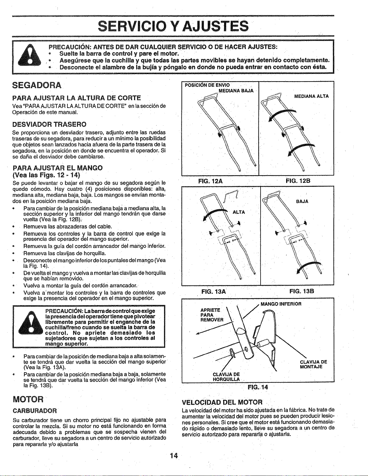
Y AJ
SEGADORA
PARA AJUSTAR LA ALTURA DE CORTE
Vea "PARA AJUSTAR LAALTURA DE CORTE" en lasecciSnde
Operaci6nde este manual.
DESVRADOR TRASERO
Se proporciona un desviador trasero, adjunto entre las ruedas
traseras de su segadora, para reducir a un mfnimo la posibilidad
que objetos sean lanzados hacia afuera de la parte trasera de la
segadora, en la _osiciSn en donde se encuentra et operador. Si
se daSa el desviador debe cambiarse,
PARA AJUSTAR EL MANGO
(Vea las Figs. 12 - 14}
Se puede levantar o bajar ei mango de su segadora segSn le
quede c6modo. Hay cuatro (4) posiciones disponibles: alta,
mediana alta, mediana baja, baja. Los mangos se envlan monta-
dos en la posici6n mediana baja.
• Para cambiar de la posiciSn mediana baja a mediana alta, la
secci6n superior y ta inferior del mango tendr_n que darse
vuelta (Vea la Fig. 12B).=
= Remueva las abrazaderas del cable.
- Remueva los controles y la barra de control que exige la
presencia del operador del mango superior.
• Remueva la gu{a del cordbn arrancador del mango inferior.
• Remueva las clavijas de horquilla.
• Desconecte et mango inferior de los puntales del mango (Vea
ia Fig. t4),
- De vuelta e! mango y vuetva a montar las ctavijas de horquilia
que se habfan removido.
• Vuelva a montar la gufa del cordSn arrancador.
• Vuelva a'montar los controles y la barra de controles que
exige la presencia del operador en el mango superior_
| _ l_rtieneque_votear
,_A t_irel enganchede !a
| _ _. ose sueit-a la barrade
ImbSJJc0_priete demasiado los
su'_'etan a los controles al
man e su enor.
= Para cambiar de la posiCibnde mediana baja a alta so]amen,
te se tendr& que dar vuelta la seccibn del mango superior
(Vea la Fig. t 3A).
* Para cambiar de la posicibn mediana baja a baja, solamente
se tendr_, que dar vuelta ta secci6n de! mango inferior (Vea
ta Fig. 13B).
POSICIbN DE ENVIO
MEDIANABAJA
FIG, 12A
ALTA
FIG. 13A
APRIETE
PARA
REMOVER
:_ MEDIANA ALTA
FIG. 12B
BAJA
FiG. 13B
MANGOINFERIOR
CLAVIJA DE
HORQUILLA
FIG. 14
CLAVIJA DE
MONTAJE
MOTOR
CARBURADOR
Su carburador tiene un chorro principal fijo no ajustable para
contr0tar la mezcla. Si su motor no est& funcionando en forma
adecuada debido a probtemas que se sospecha vienen dot
carburador, {leve su segadora a un centro de servicio autor_zado
para reparada y/o ajustada
VELOCIDAD DEL MOTOR
La velocidad deI motor ha sido ajustada en la f_,brica. No trate de
aumentar la ve!ocidad del motor pues se pueden producir lesio-
nes personales. Si oree que el motor est_ funcionando demasia-
do r_pido o demasiado lento, Ileve su segadora a un centre de
servicio autorizado para repararla o ajustarla.
14
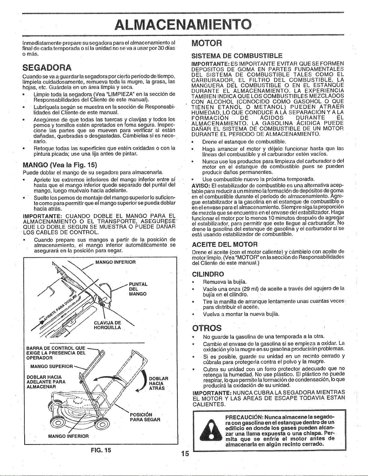
ALMACENAMiENTO
lnmediatamente prepare su segadora para el almacenamiento al _l_omo R
final de cada temporada o si la unidad no se va a usar por 30 d_'as
o mas.
SEGADORA
Cuando se va a guardar la segadora per ciert0 periodo de tiempo,
limpiela cuidadosamente, remueva toda la mugre, la grasa, las
hojas, etc. Gu_rdeta en un &rea limpia y seca.
= Limpie toda ta segadem (Vea "LIMPIEZA" en ta secci6n de
Responsabilidades del Cliente de este manua0.
* Lubriqueta Seg_n se muestra en la secci6n de Responsabi-
lidades del CIiente de este manual,
. AsegOrese de que todas ias tuercas y clavijas y todos los
pemes y tornittos est6n apretados en foma segura. Inspec-
cione las partes que se mueven para verificar si est_,n
daRadas, quebradas o desgastadas. Cambielas si es nece-
sario,
Retoque todas las superficies que est6n oxidadas o con la
pintura picada; use una lija antes de pintar.
MANGO (Yea ia Fig. 15)
Puede doblar el mango de su segadora para almacenada.
• Apriete los extremes inferiores del mango inferior entre si
hasta que et mango inferiot" quede separado del puntal del
mango, uego mu_valo hacia adelante.
= Suelte los pernos de montaje del mango superior Io suficien-
te come para permitir que el mango superior se pueda doblar
hacia atras.
IMPORTANTE: CUANDO DOBLE EL MANGO PARA EL
ALMACENAMIENTO O EL TRANSPORTE, ASEGUR_ESE
QUE LO DOBLE SEGUN SE MUESTRA O PUEDE DANAR
LOS CABLES DE CONTROL.
,, Cuando prepare sus mangos a partir de ta posici6n de
almacenamiento, et mango inferior autom&ticamente se
asegurara en la posici6n para segar.
PUNTAL
DEL
MANGO
CLAVtJA DE
HORQUILLA
BARRADE CONTROL QUE
EXIGELA PRESENCIA DEL
OPERADOR
MAN
DOBLAR HACIA
ADELANTEPARA
ALMACENAR
DOBLAR
HACIA
ATRAS
POSlClON
PARA SEGAR
MANGO iNFERIOR
SnSTEMA DE COMBUSTIBLE
IMPORTANTE: ES IMPORTANTE EVITAR QUE SE EORMEN
DEPOSITOS DE GOMA EN PARTES FUNDAMENTALES
DEL S1STEMA DE COMBUSTIBLE TALES COMe EL
CARBURADOR, EL FILTRO DEL COMBUSTIBLE, LA
MANGUERA DEL COMBUSTIBLE O EN EL ESTANQ_E
DURANTE EL ALMACENAMIENTO_ LA EXPERiENCIA
TAMB1EN IND1CA QUE LOS COMBUSTIBLES MEZCLADOS
CON ALCOHOL (CONOCIDO COMe GASOHOL O QUE
TIENEN ETANOL O METANOL) PUEDEN ATRAER
HUMEDAD, LO QUE CONDUCE A LA SEPARACION Y A LA
FORMAClbN DE _,CIDOS D URANTE EL
ALMACENAMIENTO. LA GASOLINA ACIDICA PUEDE
DANAR EL S!STEMA DE COMBUSTIBLE DE UN MOTOR
DURANTE EL PERIODO DE ALMACENAMIENTO.
• Drene el estanque de combustible.
, Haga arrancar e! motor y d6je]o funcionar hasta que las
lineas del combustible y el carburador est_n vacfos.
o Nunca use los productos para limpieza del carburador odel
motor en el estanque de combustible pues se pueden
producir da_os permanentes.
Use combustible nuevo la proxima temporada.
AVlSO: El estabilizador de combustible es una alternativa acep-
table para reducir a un minimo la formaci6n de depositos de goma
en el combustible durante el perfodo de almacenamiento. Agre-
gue estabilizador a la gasolina en el estanque de combustible o
en el envase para el almacenamiento, Siempre siga la prop0rci6n
de mezcla que se encuentra en et envasede! estabilizador. Haga
funcionar el motor pot 1omenos t0 minutos despues de agregar
el estabitizador, para permitir que este Ifegue at carburador. No
drene ta gasolina det estanque de gasolina y el carburador si se
estA usando estabilizador de combustible.
ACEITE DEL MOTOR
Drene el aceite (con el motor caliente) y cambie[o con aceite de
motor lim pie (Vea "MOTOR" en la secci6n de Responsab idades
del Cliente de este manual.)
C1LINDRO
- Remueva la bu]ia.
- Vacfe una onza (29 ml) de aceite a traves del agujero de la
buj(a en el citindro.
Tire ta manilta de arranque lentamente unas cuantas veces
para distribuir el aceite.
® Vuelva a montar la nueva bujfa.
!5
OTROS
No guarde la gasolina de una temporada a ia otra.
= Cambie el envase de la gasolina si se empieza a oxidar. La
oxidaci6n yi0 la mugre en su gasolina producirAn probtemas.
® Si es posib]e, guarde su unidad en un recinto cerrado y
cSbrala para protegerla contra el polvo y la mugre.
= Cubra su unidad con un forro protector adecuado que no
retenga la humed&d. No use plastico. Et pl&stico no puede
respirar, Io que permite la formaci6n de condensaci6n, l0 que
producir_ la oxidaci6n de su unidad.
IMPORTANTE," NU NCA CUBRA LA SEGADORA MIENTRAS
EL MOTOR Y LAS AREAS DE ESCAPE TODAWA ESTAN
CALIENTES.
_ _! estanque de ntro de un
_L_ _t sgases pueden a_can-
_ _SfaO un_achispa, Pe!-
j _ __rnotor ant.es de
almacenarla en atgOn recinto cerrado.
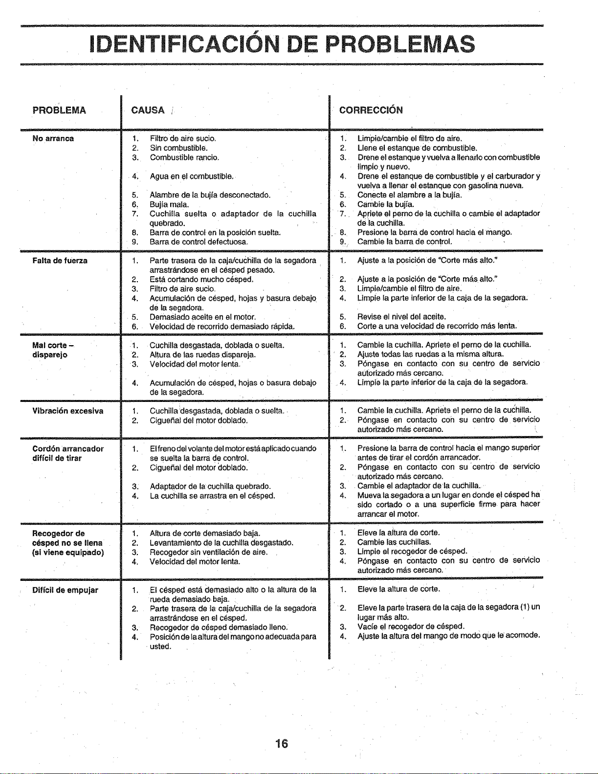
f
NTIFICACIO PROBLE
PROBLEMA
No arranca
Falta de fuerza
Mar corte"
dlspare}o
Vibraci6n excesiva
Cord6n arrancador
dif{cil de tirar
Recogedor de
c6sped no se llena
(si viene equipado)
: Diffcii de empujar
CAUSA /
I, Filtro de aire sucio.
2. Sin combustibl6.
3. Combustible rancio.
4, Agua en el combustible,
5. Alambre de ta bujfa desconectado.
6_ Bujla mala.
7. CuchiHa suelta o adaptador de la cuchilla
quebrado.
8, Barra de control en la posicj6n suelta:
9. Barra de control defectuosa.
Parte trasera de la cajaicuchilla de la segadora •
arrastr,_,ndose en el c6sped pesado.
Est8 cortando mucho c6sped,
Filtro de aire sucio,
Acumulaci6n de c_sped, hojas y basura debajo
de la segadora.
Demasiado aceite en et motor.
velocidad de recorrido demasiado rapida.
Cuchilla desgastada, doblada o sue[ta,
Attura de tas ruedas dispareja.
Velocidad de] motor tenta.
Acumulaci6n de c6sped hojas o basura debajo
de la segadora.
1. Cuchitla desgastada, doblada o suelta.
2. Ciguefial det motor doblado.
El freno delvolant e de! motor esta aplicado cuando
se suelta la barra de control.
Cigue£tal del motor doblado.
Adaptador de la cuchi]la quebrado.
La cuch[lla se arrastra en el c#sped,
1. A[tura de corte demasiado baJa,
2. Levantamiento de la cuchilta desgastado.
3_ Recogedor sin ventilaci6n de aire.
4. Velocidad del motor lenta.
El c6sped est,. demasiado alto o la altura de la
rueda demasiado baja.
Parte trasera de ]a caja/cuchi!ia de la segadora
arrastr_.ndose en el C6sped.
Recogedor de c_sped demasiado ]teno.
Posici6n de la altura de] mango no adecuada para
usted.
CORRECCI6N
1. Limpieicambie el fi!tro de aire.
2. Liana el estanquede combustible.
3. Drene elestanque y vuelva a flenarlo con combustible
limpio y nuevo,
4. Drene el estanque de combustible y el carburador y
vuelva a flenar el estanque con gasolinanueva.
5. Conecte el alambre a la bujia,
6. Cambie la buj/a.
7. Apfriete el perno de la cuchilta o cambie el adaptador
de la cuchifla.
8. Presione la barra de control hacia el mango.
9, Cambie la barra de control.
t. Ajuste a ta p0sicibn de "Corte m&s alto."
Ajuste a la posici6n de "Corte m&s alto."
Limpietcambie e] filtro de aire,
Limpie la parte inferior de la caja de ia segadora.
5. Revise el nivel del aceite.
6. Corte a una ve]ocidad de recorrido m_,s lenta.
1. Cambie la cuchilla. Apriete el perno de la cuchilla.
2. Ajuste todas las ruedas ala misma altura.
3. P6ngase en contacto con su centro de serv cio
autodzado m&s cercano:
4. Limpie la parte inferior de la caja de la segadora.
1. Cambie la Cuchilla. Apdete et perno de la cu_hilla.
2. P6ngase en contacto con su oentro de servicio
autorizado mAs cercano. _
1. Presione la barra de control hacia el mango superior
antes de tirar el co_Sn arrancador.
2. P6ngase en contaCto con su 'centro de servicio
autodzado m&s cercano.
3, Cambie el adaptador data cuChilla.
4. Mueva la segadora a un lugar en donde e! cdsped ha
sido cortado o a una supefficie firme para hacer
arrancar el motor.
1. Eleve Iaaitura de corte.
2. Cambia las cuchillas.
3. Umpie el recogedor de cesped.
4: PSngase en €ontacto con su centro de Servicio
autodzado mas cercano.
Eleve laaltura de c0rte.
Eleve la parte trasera de la caja de la Segadora (t) un
tugar m&s alto.
Vacie e! recogedor de c_sped,
Ajuste la altura del mango de mod0 que le acomode.
16

NOTAS
17
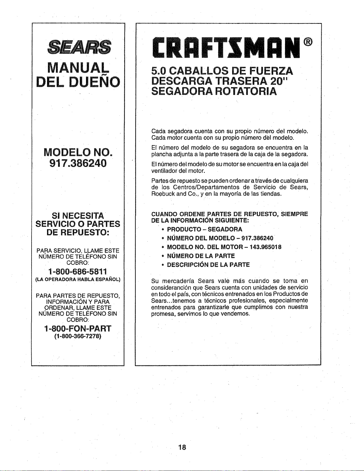
MANUAL
EL DUENO
MODELO NO.
917.386240
SI NECES|TA
SERVIClO O PARTES
DE REPUESTO:
PARA SERVICIO, LLAME ESTE
NUMERO DE TELEFONO SIN
COBRO:
1-800=686-5811
{LA OPERADORA HABLA ESPA_OL)
PARA PARTES DE REPUESTO,
aNFORMACIBN Y PARA
ORDENAR, LLAME ESTE
NOMERO DE TELI_FONO SIN
COBRO:
1-800-FON-PART
(1-800.,366-7278)
CRRFrSMRN ®
5.0 CABALLOS DE FUERZA
DESCARGA TRASERA 20"
SEGADORA ROTATORIA
Cada segadora cuenta con su propio n0mero del modelo.
Cada motor cuenta con su propio nt_mero del modelo.
E! nt3mero del modelo de su segadora se encuentra en la
plancha adjunta a la parte trasera de la caja de la segadora.
Et nQmero del modelo de su motor se encuentra en la caja del
ventilador del motor.
Partes de repuesto se pueden ordenar a travBs de cualquiera
de los Centros!Departamentos de Servicio de Sears,
Roebuck and Co,, y e n la mayoria de las tiendas.
CUANDO ORDENE PARTES DE REPUESTO, _SIEMPRE
DE LA INFORMACION SIGUIENTE:
• PRODUCTO- SEGADORA
• NOMERO DEL MODELO -917.386240 _
• MODELO NO. DEL MOTOR - 143.965018
° NOMERO DE LA PARTE
° DESCRIPCIBN DE LA PARTE
Su mercaderfa Sears vate mAs cuando se toma en
consideranciSn que Sears cuenta con unidades de servicio
en todo el pals, con t_cnicos entrenados en los Productos de
Sears...tenemos a tBcnicos profesion_tes, especialmente
entrenados para garantizarle que cumplimos con nuestra
promesa, servimos Io que vendemos.
18