Loading ...
Loading ...
Loading ...
SERVICE AND ADJUSTMENTS
Now proceed to the "Chain Adjustment" section.
CHAIN REPLACEMENT (Fig. 36, 37, 38 & 39)
_ CAUTION: Wear protective gloves when han-
dling chain.The chain is sharp and can cut you
even when it is not moving.
it is normal for a new chain to stretch. Because
of this initial stretch during the first 15-30 i
minutes of operation you should recheck your
chain tension frequently and adjust the chain
tension as required. See chain tension section.
Move on/stop switch to the "Stop" position.
• Replace the old chain when it becomes worn or dam-
aged.
• Use on!y the Low-Kickback replacement chain specified
in the repair parts list or as specified on the replacement
bar and chain decal located on the chain saw.
• See your Sears Service Center to replace and sharpen
..individual cutters for matching your chain.
•,Loosen and re"move the 2 bar clamp nuts.
• Remove I:Jarclamp.
• Remove the old chain.
• .Turn adjusting_,screw by hand counterclockwise until
.adjusting pin just touches the stop.
• Slide guide bar behind clutch drum until guide bar stops
, against clutch drum sprocket.
• Carefully remove new chain from package. Hold chain
with the drive links as shown in Figure 37.
,Piace chain over and behind the clutch.
, Fit bottom of drive links between teeth in sprocket nose.
, Fit chain drive links into top of guide bar. Figure 38.
Bar Clamp
\
Clamp Nuts
Figure 36
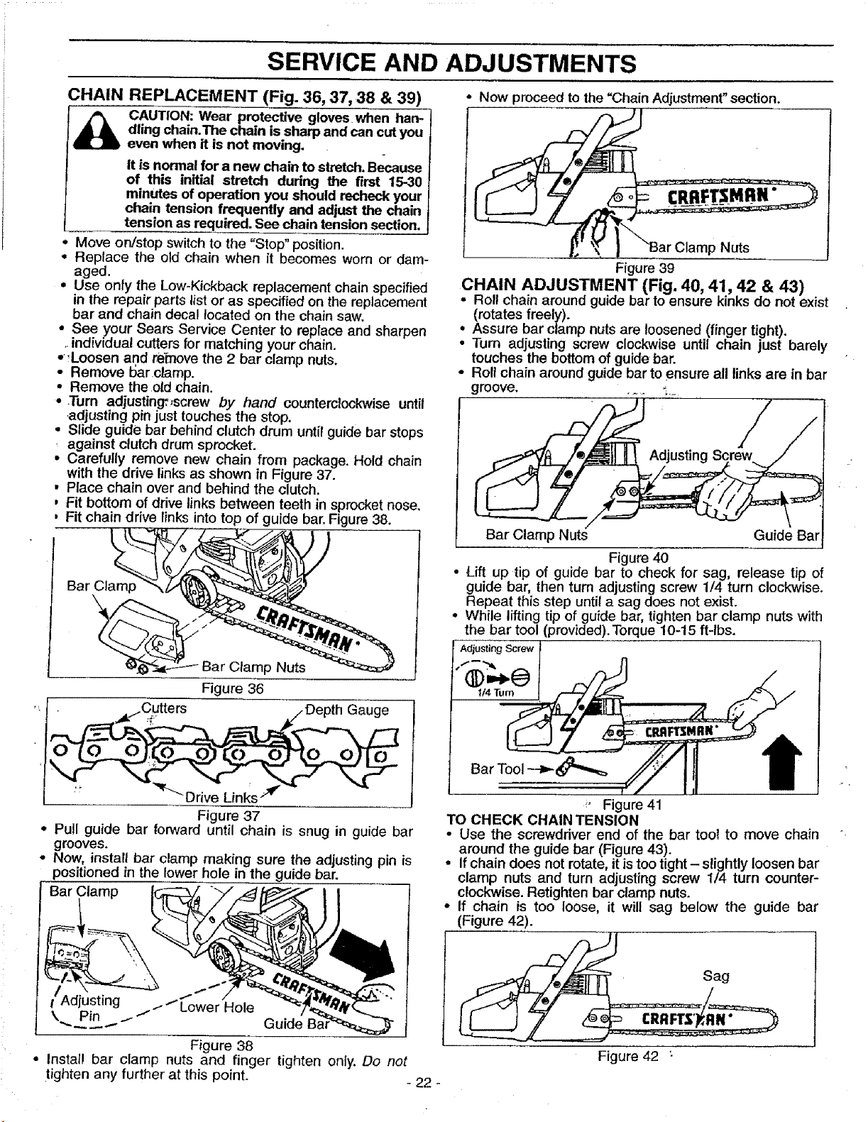
• _/Cutte rs _/Depth Gauge
Figure 37
• Pull guide bar forward until chain is snug in guide bar
grooves.
• Now, install bar clamp making sure the adjusting pin is
positioned in the lower hole in the guide bar.
Bar Clamp
Adjusting .--"_
tt Lower Hole
\ Pin .i Guide
Figure 38
• install bar clamp nuts and finger tighten only. Do not
tighten any further at this poinL - 22 -
Nuts
Figure 39
CHAIN ADJUSTMENT (Fig. 40, 41, 42 & 43)
Roll chain around guide bar to ensure kinks do not exist
(rotates freely).
• Assure bar clamp nuts are loosened (finger tight).
• Turn adjusting screw clockwise until chain just barely
touches the bottom of guide bar.
• Roll chain around guide bar to ensure all links are in bar
groove ...... -,_
Bar Clamp Nuts Guide Bar
Figure 40
• Lift up tip of guide bar to check for sag, release tip of
guide bar, then turn adjusting screw 1/4 turn clockwise.
Repeat this step until a sag does not exist.
• While lifting tip of guide bar, tighten bar clamp nuts with
the bar tool (provided). Torque 10-15 ft-lbs.
Adjusting Screw
U4Tum
_, Figure 41
TO CHECK CHAIN TENSION
• Use the screwdriver end of the bar tool to move chain
around the guide bar (Figure 43).
• Ifchain does not rotate, it istoo tight- slightly loosen bar
clamp nuts and turn adjusting screw 1/4 turn counter-
clockwise. Retighten bar clamp nuts.
• If chain is too loose, it will sag below the guide bar
(Figure 42).
_ ..... Sag
Figure 42 :
Loading ...
Loading ...
Loading ...