Loading ...
Loading ...
Loading ...

Figure 6
see legend below)
Part number 550-100-325/0419
9
AquaBalance
®
Series 2 Wall Mount Gas-fired Water Boiler – Boiler Manual
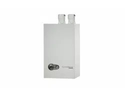
1. Boiler Supply (outlet) connection, (male, 1” NPT on the 80/120 boilers, 1” NPT on the 155 boiler).
2. Boiler Return (inlet) connection, (male, 1” NPT on the 80/120 boilers, 1” NPT on the 155 boiler).
Recommend Near Boiler Piping to be 1-1/4” NPT or larger for the 155 boiler. Bushing 1” x 1-1/4” NPT at Supply (outlet) and Re-
turn (inlet) not shown.
(field supplied by installer).
3. Boiler relief valve, shipped loose with boiler — .
3a. Insert a ¾” NPT plug in the relief valve tapping of the reducing tee. This MUST BE REMOVED
after the test and the relief valve mounted here.
4. Pressure/temperature gauge,
(field supplied) by installer, (Optional – can use boiler gauge).
5a. Reducing tee, 1” x 1” x ¼” on
the 80/120 boilers, NPT, 1-1/4” x 1-1/4” x ¼” on the 155 boiler (field supplied) by installer .
5b. Tee, NPT, 1” x 1” x ¾” on
the 80/120 boilers, 1-1/4” x 1-1/4” x ¾” on the 155 boiler (field supplied) by installer.
6. Nipple, NPT, 1” x close on
the 80/120 boilers, NPT, 1-1/4” x close on the 155 boiler (field supplied) by installer.
7. Nipple, NPT, 1” x close on
the 80/120 boilers, NPT, 1-1/4” x close on the 155 boiler (field supplied) by installer.
8. Isolation valve on supply connection,
(field supplied) by installer (1” NPT on the 80/120 boilers, 1-1/4” NPT on the 155 boiler).
9. Isolation valve on return connection, (field supplied) by installer (1” NPT on the 80/120 boilers, 1-1/4” NPT on the 155 boiler).
10. ¾” NPT boiler drain valve, (field supplied) by installer — after hydrostatic testing, move drain valve to lowest point on the return piping
if not already there.
3 Prepare boiler continued
Figure 5
(see
legend below) (Combi boiler shown)
2
3
1
10
Loading ...
Loading ...
Loading ...