
OPERATION
MANUAL
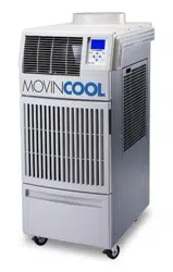
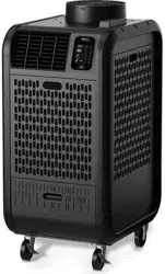
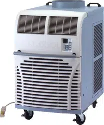
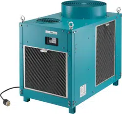
CLIMATE PRO D12
CLIMATE PRO D18
R
R
R

2
3
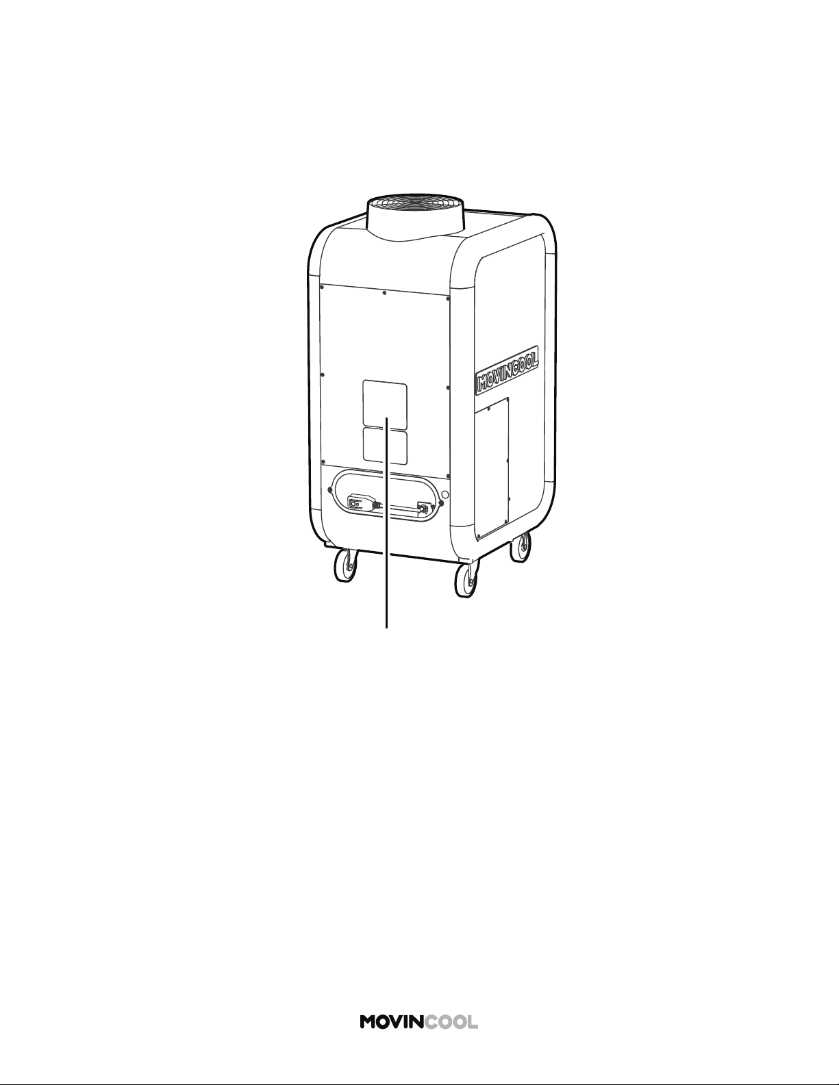
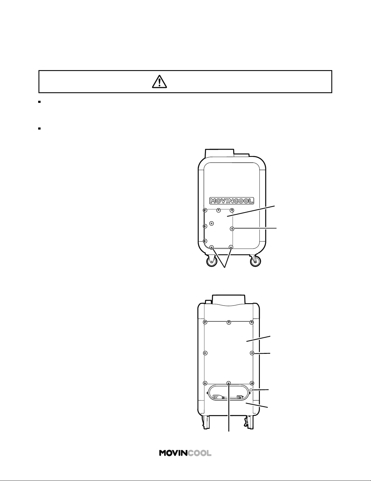
SERIAL NUMBER LOCATION
Please read this manual carefully and keep it for future reference.
La versión en español está disponible en www.movincool.com
La version française est disponible sur www.movincool.com
© 2020 DENSO PRODUCTS AND SERVICES AMERICAS, INC. All rights reserved.
MovinCool® and Climate Pro® are registered trademarks of DENSO Corporation.
00
Month Year Sequential Model
number
name
00 0000 000

4
TABLE OF CONTENTS
SERIAL NUMBER LOCATION 3
SAFETY PRECAUTIONS
6
NAMES OF PARTS
10
CONTROL PANEL
12
Overview 12
Home Screen 13
Mode Screen 14
Menu Screen 15
Se ing Screen 16
INSTALLATION
17
Placement of the Unit 17
Accessories 18
Typical Installation Options 19
Plugging in the Unit 20
LCDI (Leakage Current Detection Interrupter) Power Cord 21
External Warning Device Connection 22
External Alarm Device Connection 24
INITIAL SETTINGS
26
Privacy Disclosure Screen 26
Selecting Time Zone 27
Se ing Daylight Savings 30
Clock Se ing 32
Removing Securing Tapes and Sheet 35
OPERATION
36
Cool Mode 36
Heat Mode 38
Auto Mode 40
Fan Only Mode 42
Schedule Mode 44
Starting Schedule Mode Operation 45
Stopping Schedule Mode Operation 47
Outside Operating Range 48
5
Defrost
49
Temporary Stop During Schedule Mode 50
Se ing / Editing / Viewing Schedule 51
Clearing Schedule 54
Adjusting Brightness 56
Fan Mode 58
Changing Temperature Scale 60
Key Lock 62
Key Unlock 63
Temporary Stop During Key Lock 64
Service Information 65
Self-Diagnostic Codes 68
List of Self-Diagnostic Codes 69
Emptying the Drain Tank 70
Condensate Pump Kit (Optional Accessory) 71
MAINTENANCE
72
Cleaning Air Filters 72
Cleaning the Unit 73
Before Long Term Storage 73
TECHNICAL SPECIFICATIONS
74
TROUBLESHOOTING
76
WARRANTY STATEMENT
77
DATA PRIVACY DISCLOSURE
78
6
SAFETY PRECAUTIONS
OPERATION
Do not touch electrical parts or switch bu on with wet or oily hands.
This may cause fi re, electric shock or malfunction.
Do not put a fi nger, a rod or other objects into the air outlet or inlet.
Touching fan or heat exchanger may result in injury or malfunction.
Do not place or use flammable spray near the unit.
This may cause explosion or fi re.
Do not use the unit in an environment which contains excessive amounts of flammable
gas, conductive dust or oil.
This may cause explosion or fi re.
Do not use the unit in an environment which contains corrosive gas or vapor.
This may deteriorate the insulation and result in electric shock or fi re. This may corrode
pipes and result in leaks.
Do not wash the unit with water.
This may cause fi re, electric shock or malfunction.
Safety symbols and meanings
This must not be done. This must be done. Ensure unit is grounded.
WARNING
Indicates a hazardous situation which, if not avoided,
could result in death or serious injury.
CAUTION
Indicates a hazardous situation which, if not avoided, could
result in minor or moderate injury, damage to the unit or its
components and/or property.
Serious injuries include: loss of vision, bodily injuries, burns, electric shock, fractures or poisoning, which
require prolonged medical treatment and will leave after-effects.
Minor or moderate injuries include: bodily injuries, burns or electric shock, which do not require prolonged
medical treatment.
Property includes: housing, household goods, livestock or pets.
This appliance is not intended for use by persons (including children) with reduced physical, sensory
or mental capabilities, or lack of experience and knowledge, unless they have been given supervision
or instruction. Children should be supervised to ensure that they do not play with the appliance.
To reduce the risk of injury or property damage, read “Safety Precautions” carefully before operating
the appliance.
The seriousness is classified by the following indicators:
WARNING
7
Do not point the airflow directly on your body for long periods of time or make your
body too cold.
This may result in health problems.
Do not use an extension cord or multi-socket plug.
This may generate heat and cause a fire or electric shock.
Do not use damaged power cord/plug or modify the cord/plug.
This may generate heat and cause a fire or electric shock.
Do not heat, pull, wind, bundle or place heavy objects on the power cord.
This may generate heat and cause a fire or electric shock.
If an abnormality such as a burning smell occurs, stop the operation and turn the
breaker OFF.
This may cause fire, electric shock or malfunction. Stop the operation immediately
and consult your MovinCool dealer or qualified technician.
INSTALLATION
Do not install the unit in a place where flammable gas may generate, flow, gather or
leak. Do not install the unit in a place where conductive dust or oil is floating.
This may cause explosion or fire.
Installation and electrical work must be performed in accordance with national wiring
regulations by qualified electrical personnel.
Improper installation or electrical work may cause fire, electric shock, injury,
malfunction or water leaks.
Install an earth leakage circuit breaker to the mains power source.
Improper installation or electrical work may cause fire, electric shock, injury,
malfunction or water leaks.
Use only official accessories and consult your MovinCool dealer or qualified technician
for installing the accessories to the unit.
Non-genuine accessories or incomplete installation may cause fire, electric shock or
water leaks.
Ensure effective grounding.
Incomplete grounding may result in fire or electric shock. Contact your MovinCool
dealer or qualified technician.
RELOCATION/REPAIR
Do not repair, disassemble or modify the unit yourself.
This may cause fire, electric shock, injury, water leaks or malfunction. Contact your
MovinCool dealer or qualified technician.
If the unit is soaked due to natural disaster, consult your MovinCool dealer.
If you keep using the unit, it may result in fire, electric shock or malfunction.
8
OPERATION
Do not operate without panels or fan guards.
Touching high-voltage, high-temperature or rotating parts may cause electric shock,
injury or burns.
Do not use the unit in sloping, non-level areas.
Use the unit only on a smooth, flat, level surface. There is a risk of electric shock due
to water leaks or injury due to toppling.
Do not operate the unit without air filters.
Touching the heat exchanger may cause injury. If dust or dirt enters the unit, it may
result in malfunction or poor operation of the unit.
Do not tilt the unit while moving to another place.
This may cause injury due to toppling or property damage due to water leaks from the
unit.
Do not press the control buttons with a sharp-pointed object such as a ballpoint pen
or a fingernail.
This may cause electric shock or malfunction.
Do not sit, stand or place objects on top of the unit.
This may cause injury due to toppling or falling.
Do not place water containers on the unit.
If the containers fall over, water spilling into the unit may cause electric shock or
malfunction.
Do not expose combustion appliances to the direct air flow.
This may cause incomplete combustion.
Do not expose animals or plants to the direct air flow.
This may have negative effects on plants and animals.
Do not use the unit to preserve food, plants, animals, precision devices, or works of art.
This may have negative effects on the quality of objects.
Ensure adequate ventilation when operating with combustion appliances.
Poor ventilation may cause headaches due to lack of oxygen.
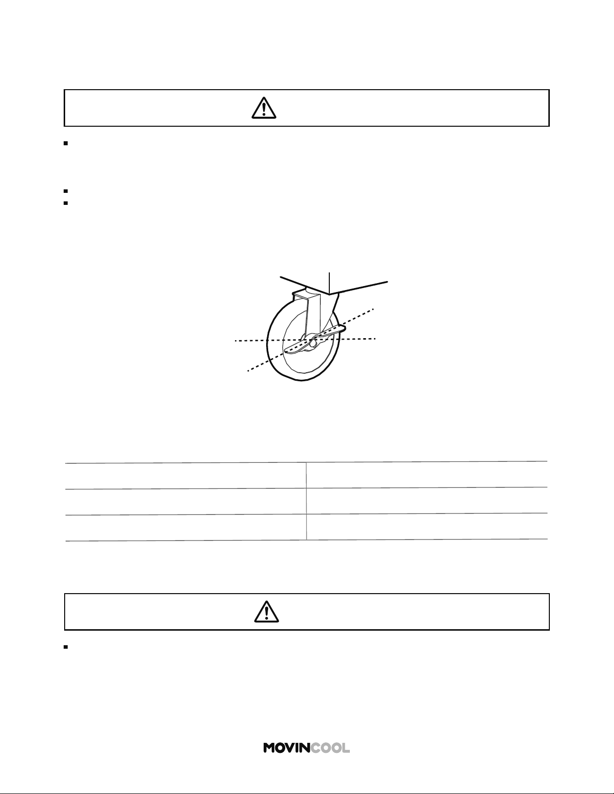
Lock the caster while operating.
Failure to lock casters may cause injury due to moving or falling.
CAUTION
9
Unlock the caster to move the unit.
Failure to unlock the caster may cause injury due to falling.
When the tank is full, empty water immediately.
Water leaks from the unit may cause property damage, or injury due to wet floor.
Never pull the power cord to disconnect the unit from the outlet. Grasp the plug directly and
pull it from the outlet.
This may cause generation of heat or fi re due to cord damage.
When cleaning, wipe the external surface with either a dry cloth or a cloth dampened
in a mild cleaner.
If you use organic solvent such as benzene or thinner, it may cause a crack or a scratch.
This may result in electric shock or injury.
When cleaning, stop the operation and remove the power plug from the outlet.
If you touch high-voltage or rotating parts, it may cause electric shock or injury.
When not using the unit for a long period of time, disconnect the power plug.
Failure to disconnect the power plug may cause generation of heat or fire due to
accumulated dust.
INSTALLATION
Do not install the unit on ships, in vehicles or locations subject to vibration.
Improper installation may cause injury, refrigerant leaks, water leaks or malfunction.
Do not expose the unit to rain or an environment where it may be exposed to excess
water.
This may cause electric shock or leakage.
Install the unit in a place which is strong enough to withstand the weight of the unit.
Improper installation may cause injury or the unit damage due to falling.
Install spark guards if the unit is installed in area where sparks are present.
Improper installation may cause fire or water leaks.
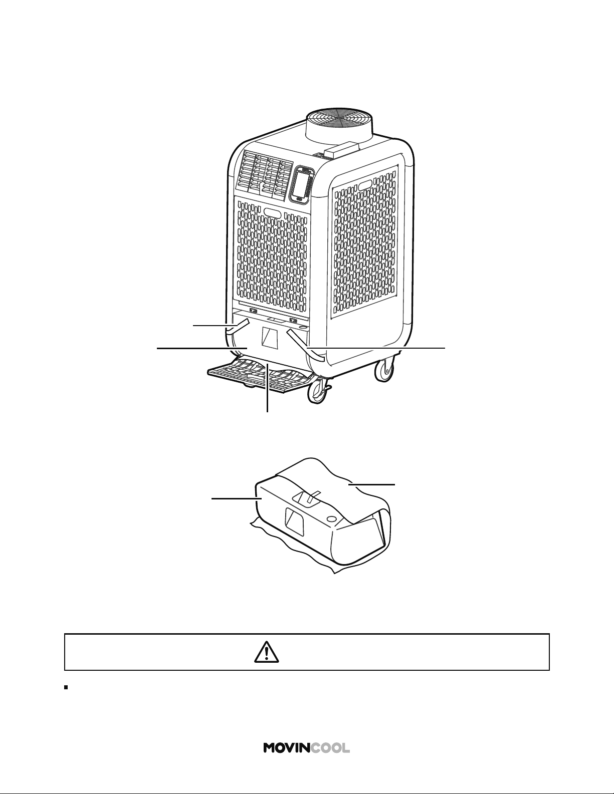
10
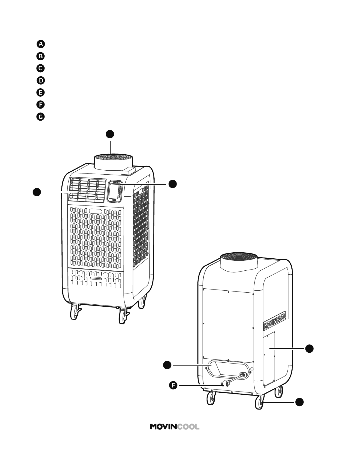
NAMES OF PARTS
Exhaust Flange
Cold / Hot Air Outlet Grill
Caster
Power Cord Holder
Control Panel
Service Panel
Power Cord
B
B
C
A
G
D
E
11
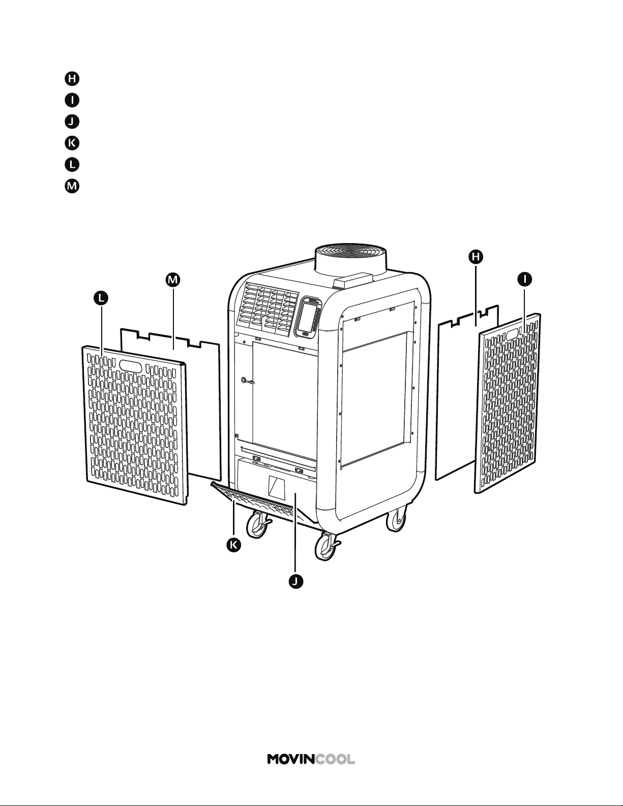
NAMES OF PARTS
Outdoor Heat Exchanger Air Filter
Drain Tank
Indoor Heat Exchanger Air Inlet Panel
Outdoor Heat Exchanger Air Inlet Panel
Drain Tank Cover
Indoor Heat Exchanger Air Filter
I
12
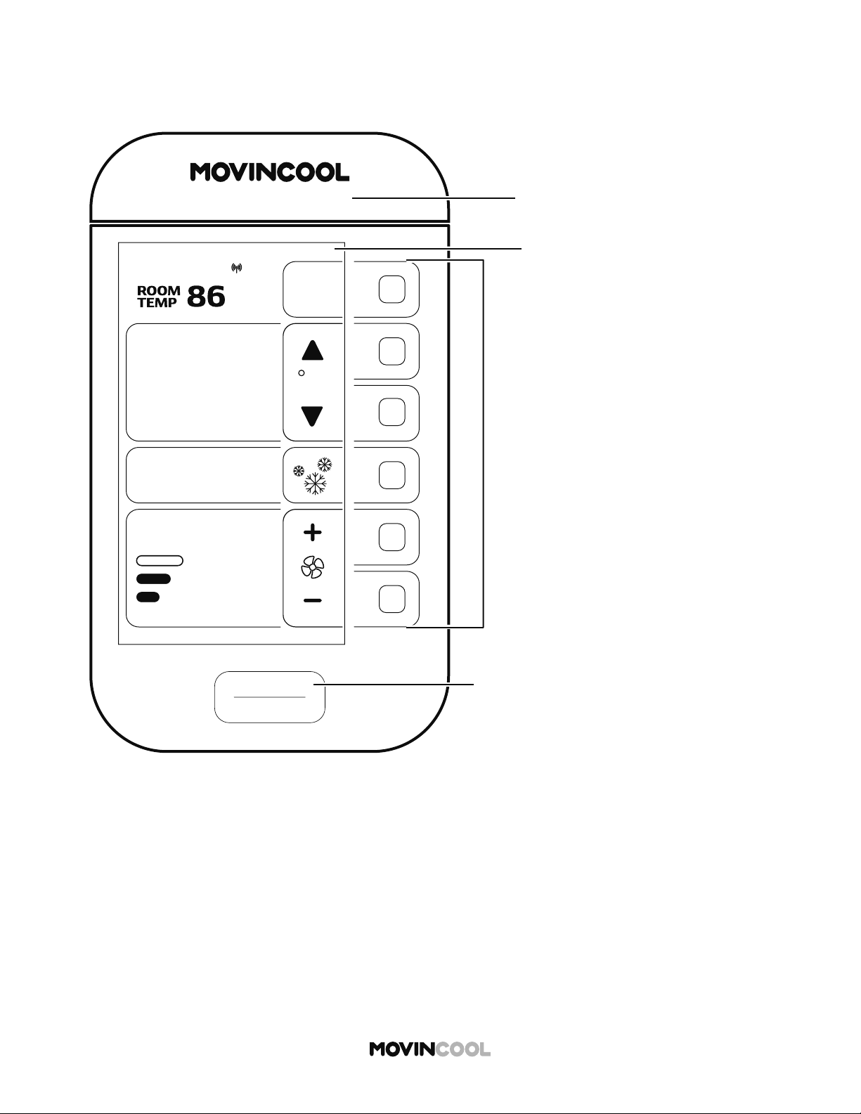
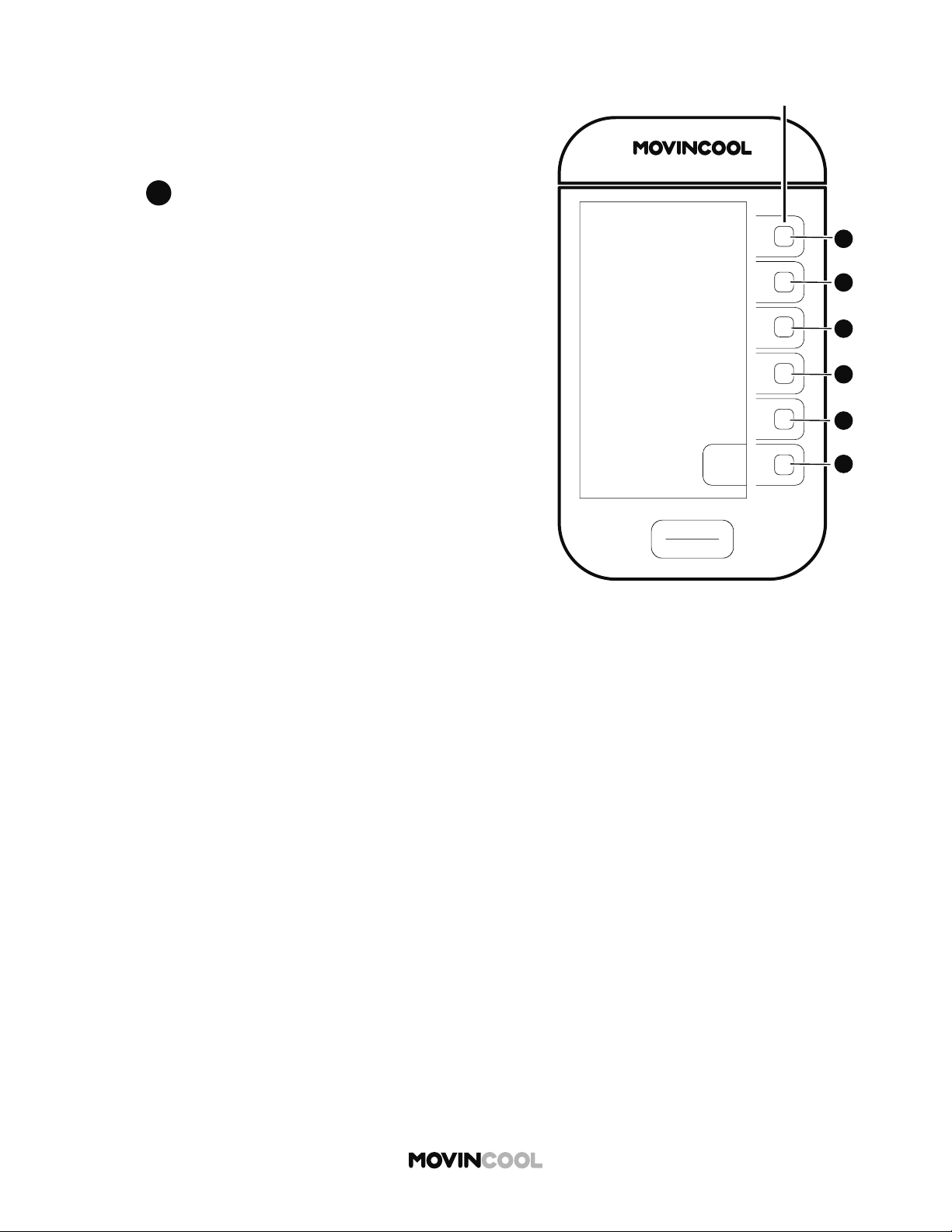
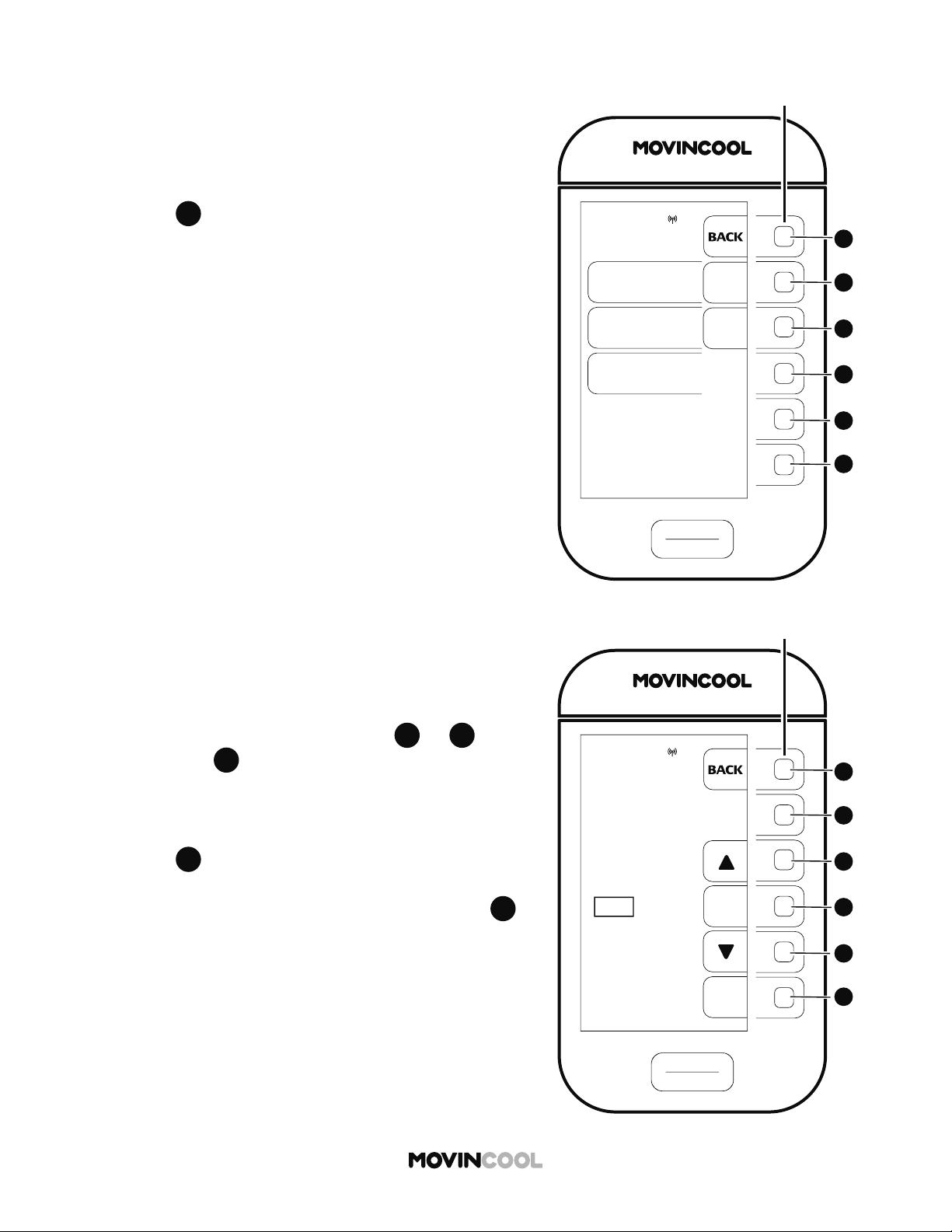
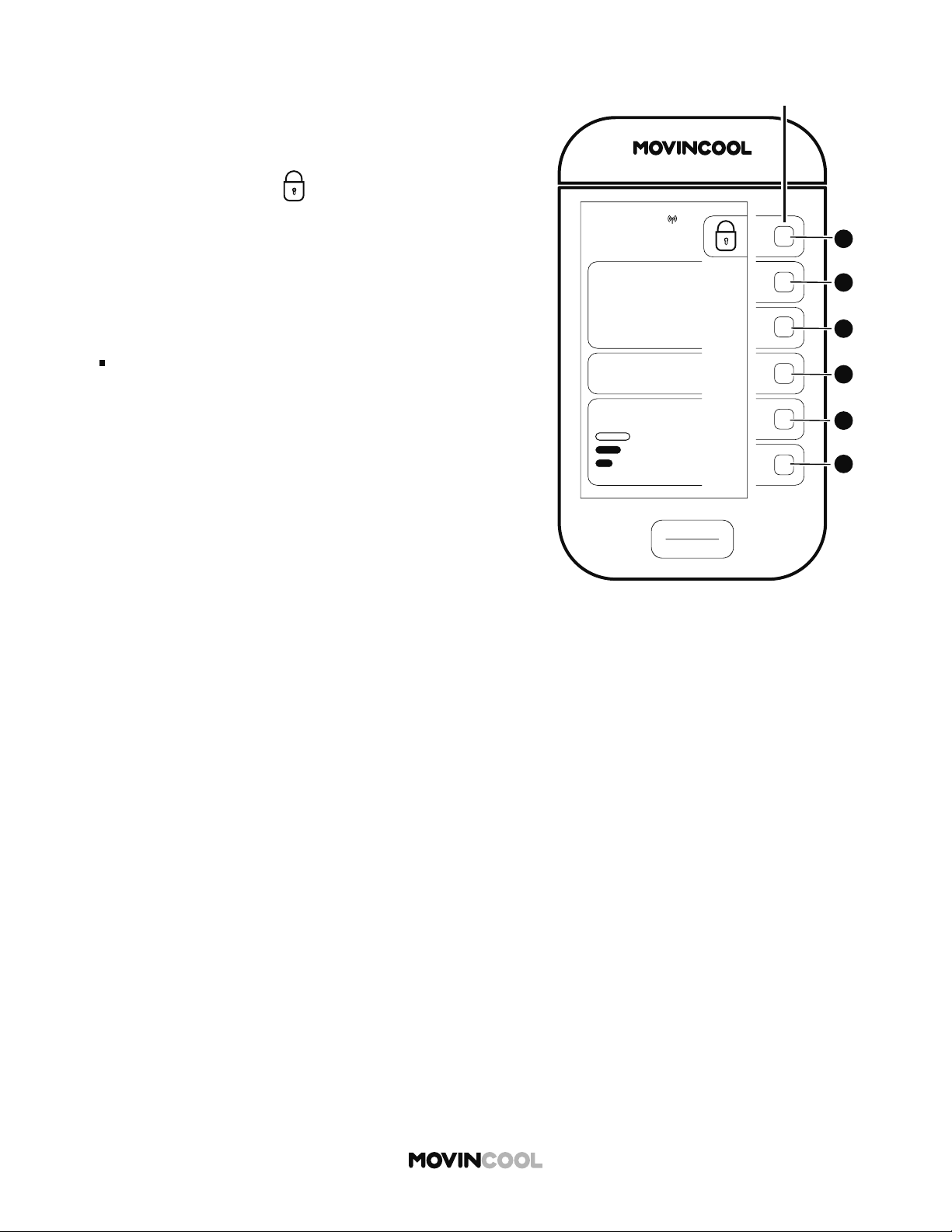
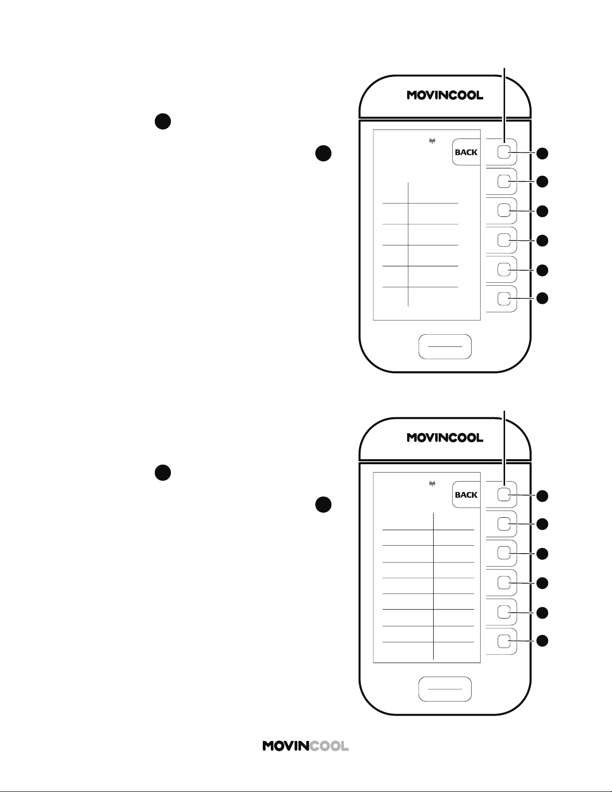
CONTROL PANEL
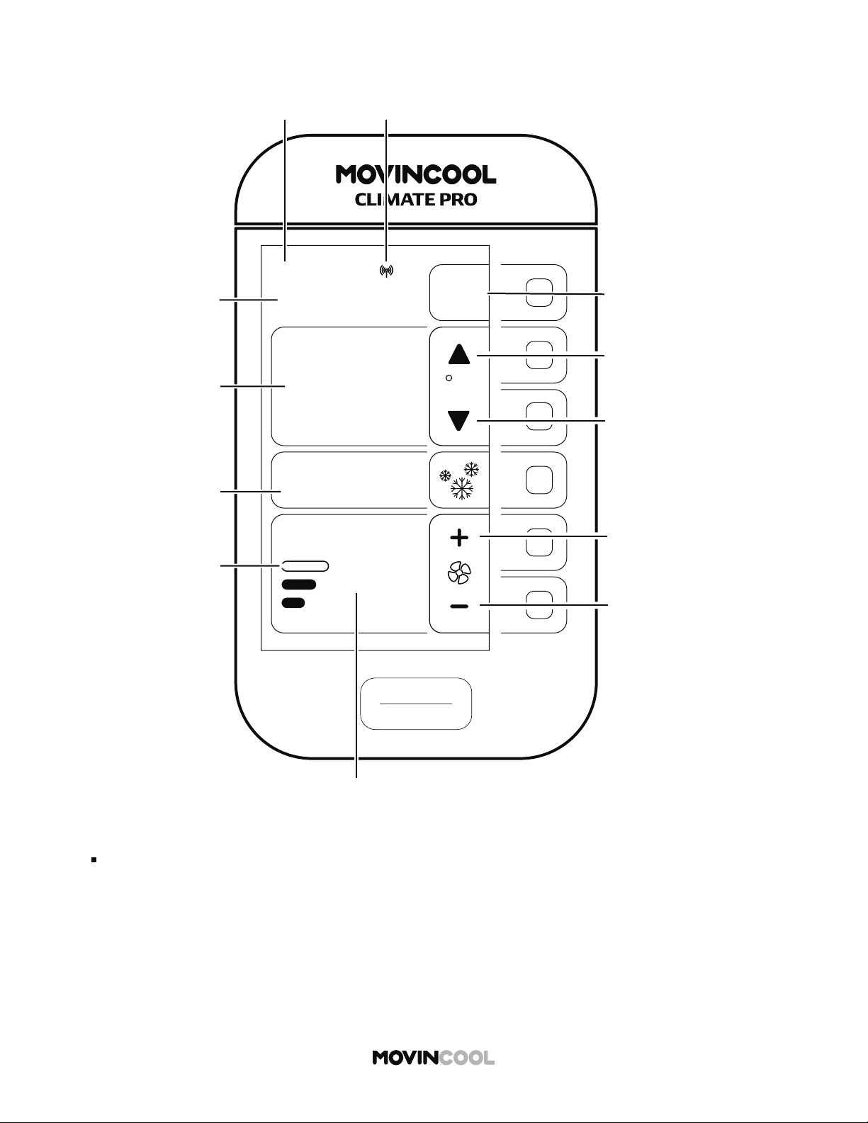
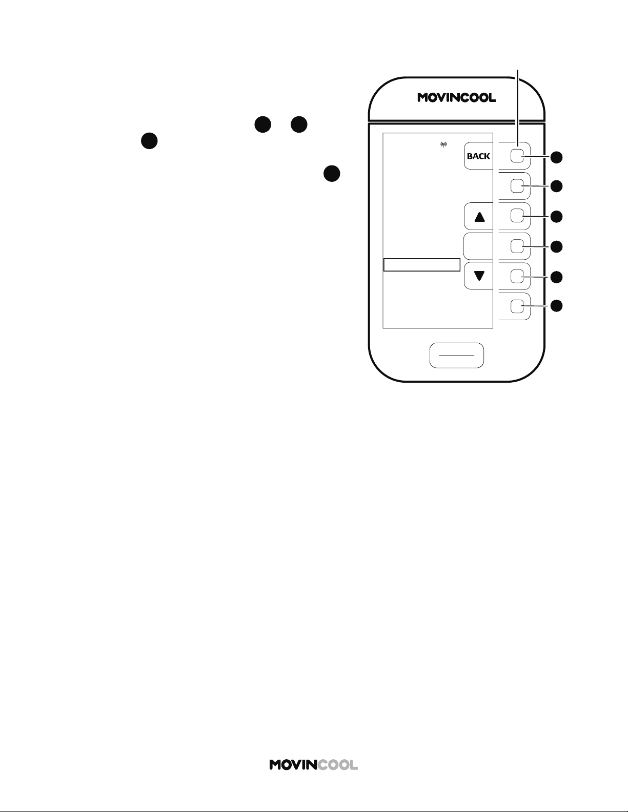
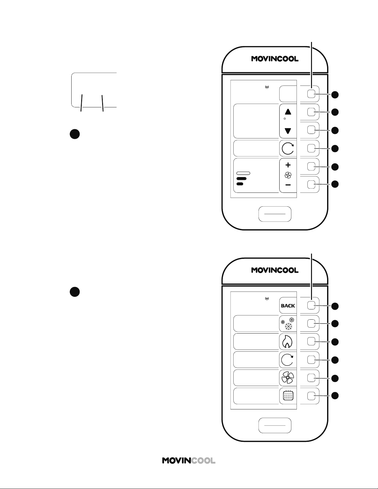
OVERVIEW
START
STOP
AUTO
COOL
75
MODE
FAN SPEED
SET TEMP
MENU
MON
12:00 PM
M
START/
S
“STAR
T
“STOP”
Mul
t
Pre
s
valu
e
Acti
v
F
CLIMATE PRO ___
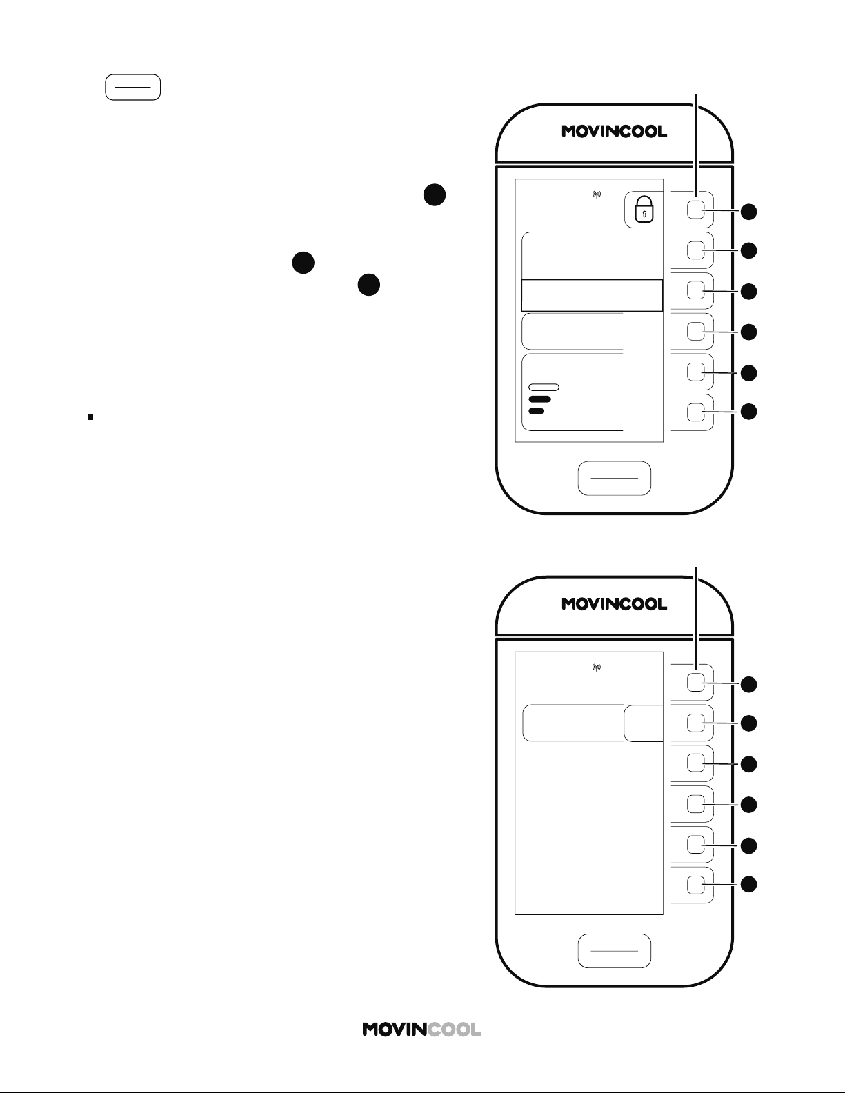
Multi-function bu ons
Press the bu ons to set the adjacent
values on the LCD screen.
Active bu ons will be lit.
START/STOP bu on
“START” is active only on the HOME screen.
“STOP” is active on all screens.
Model Name and Designation
LCD
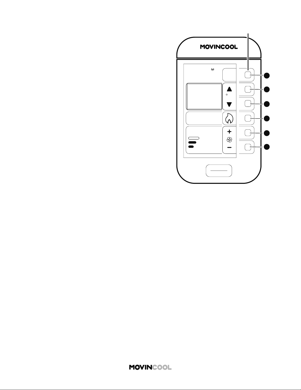
13
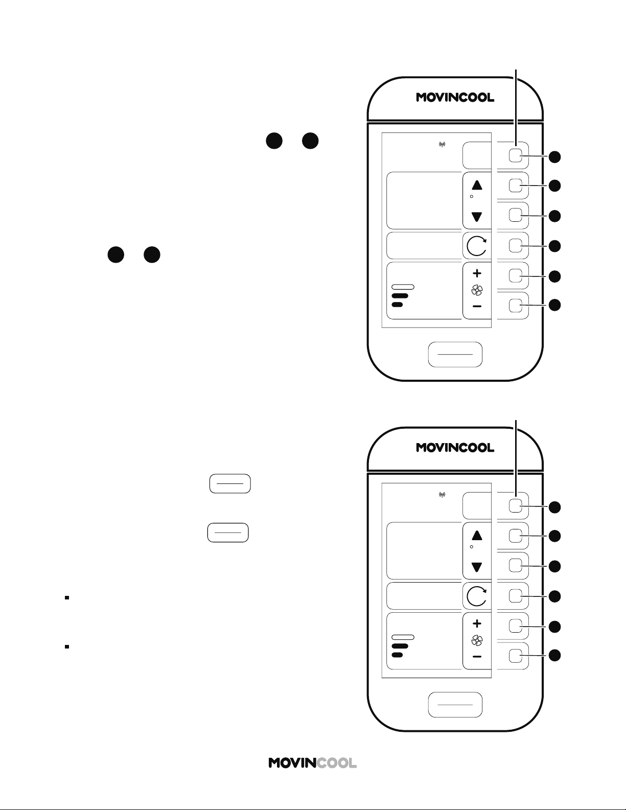
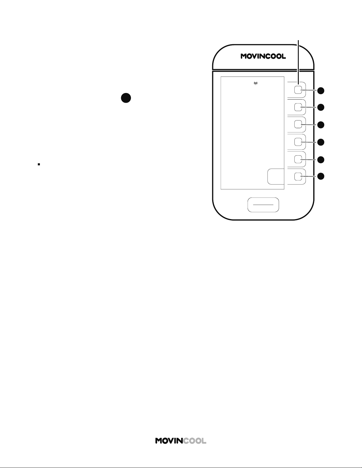
HOME SCREEN
Note:
If no bu on is pressed for 15 minutes, the screen saver appears. Press any bu on to return to
the HOME screen.
START
STOP
AUTO
COOL
75
86
ROOM
TEMP
MODE
FAN SPEED
SET TEMP
MENU
MON
12:00 PM
F
MovinCool ConnectDay/Time
Menu
Increase set temperature
Decrease set temperature
Increase fan speed
Decrease fan speed
Fan mode: On/Auto
Room temperature
Set temperature
Mode:
Cool/Heat/Auto
Fan/Schedule
Fan Speed:
Hi/Mid/Low
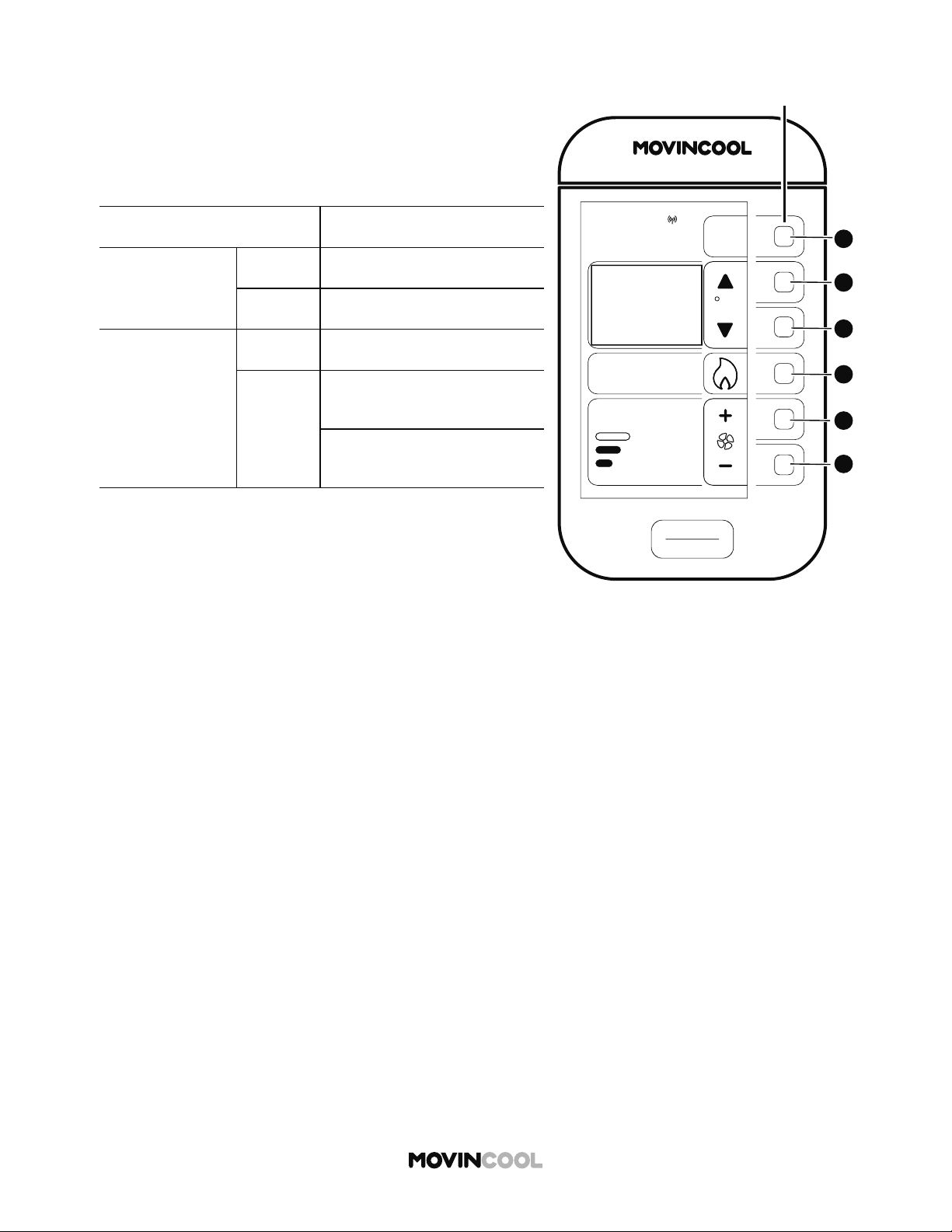
14
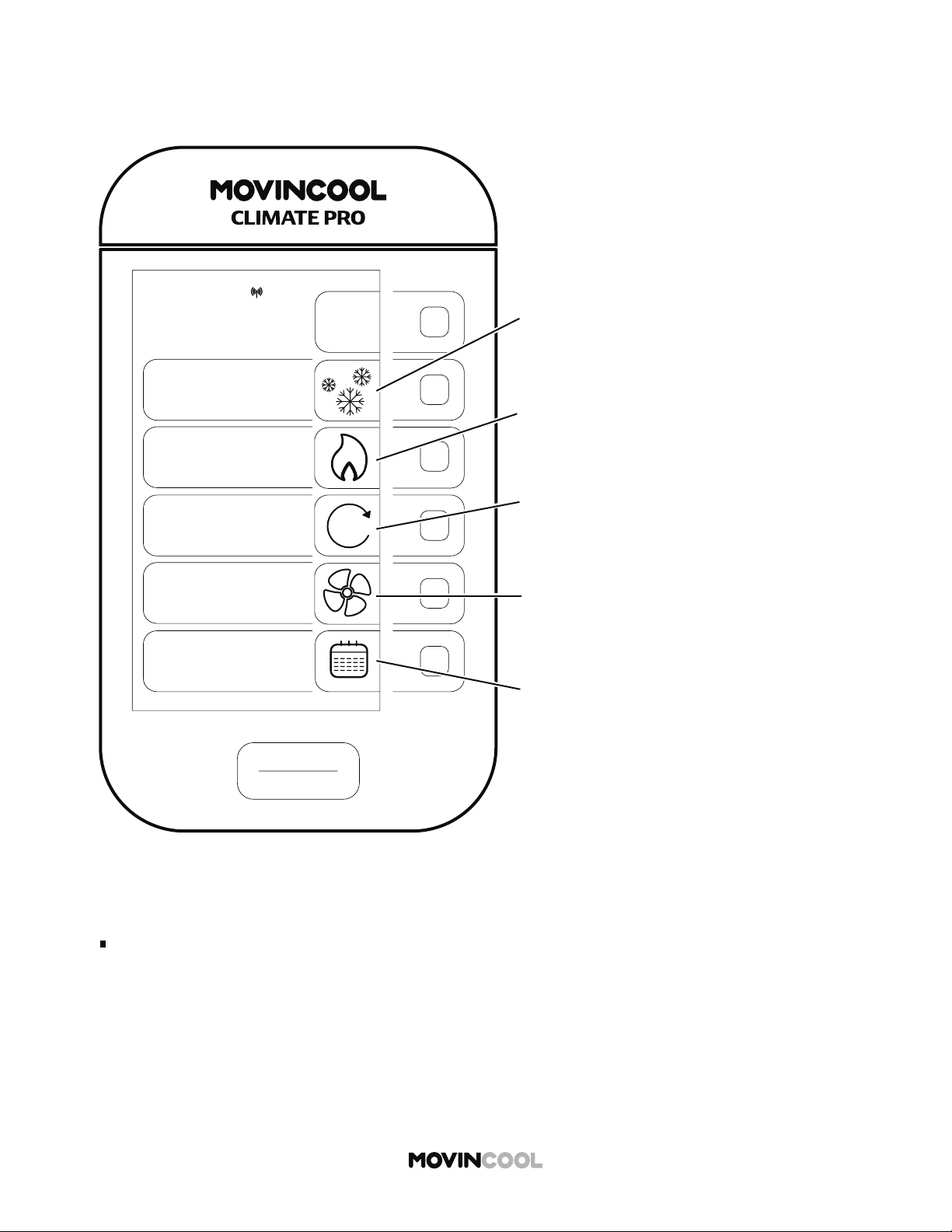
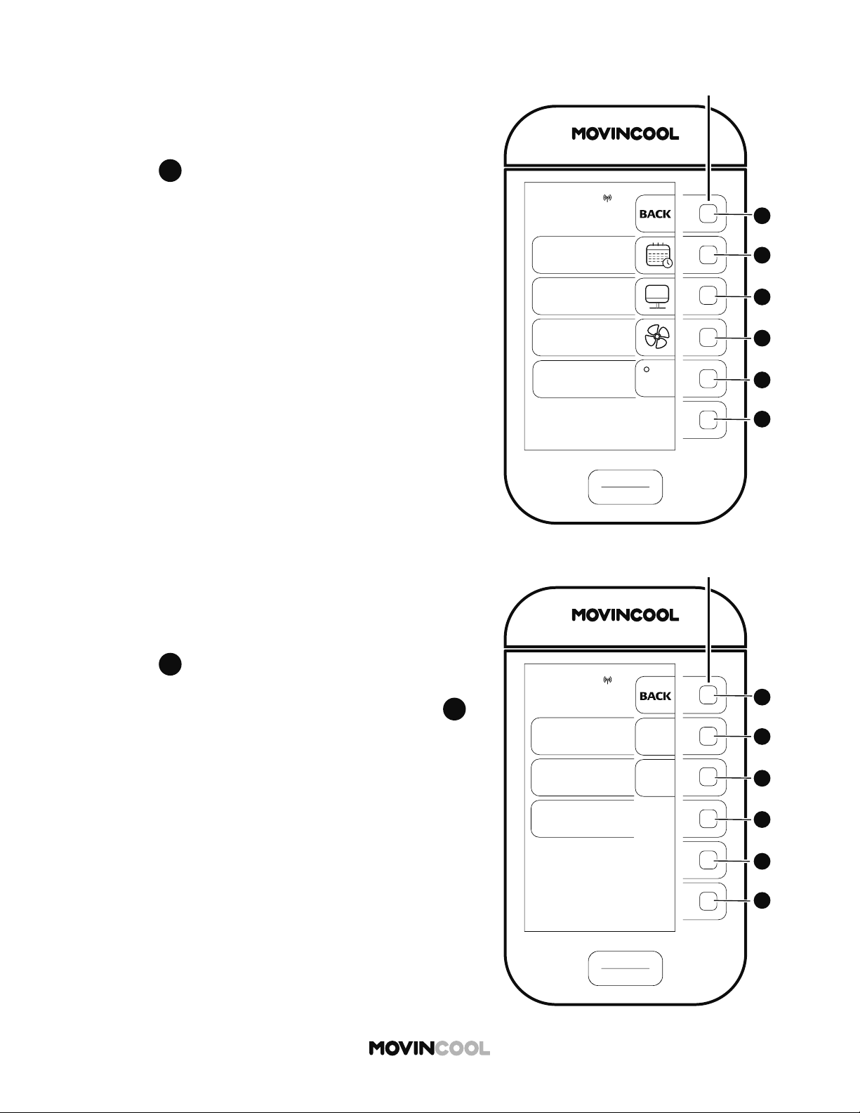
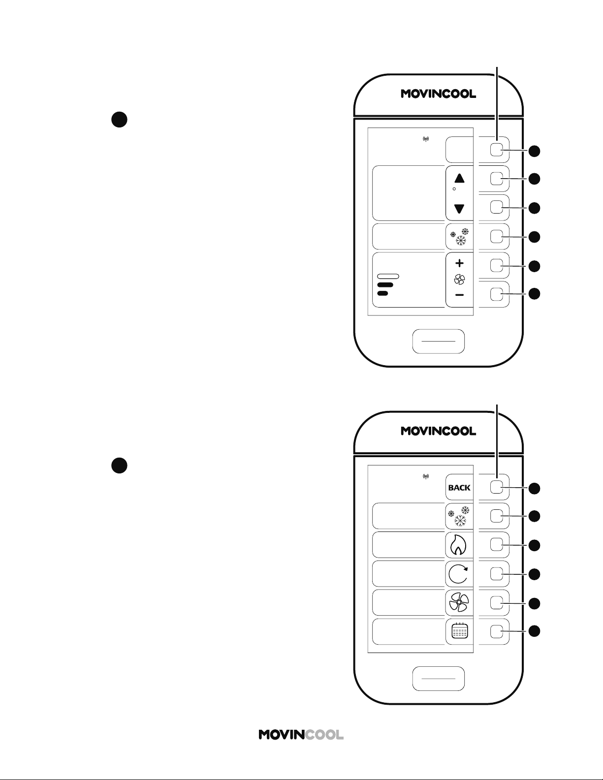
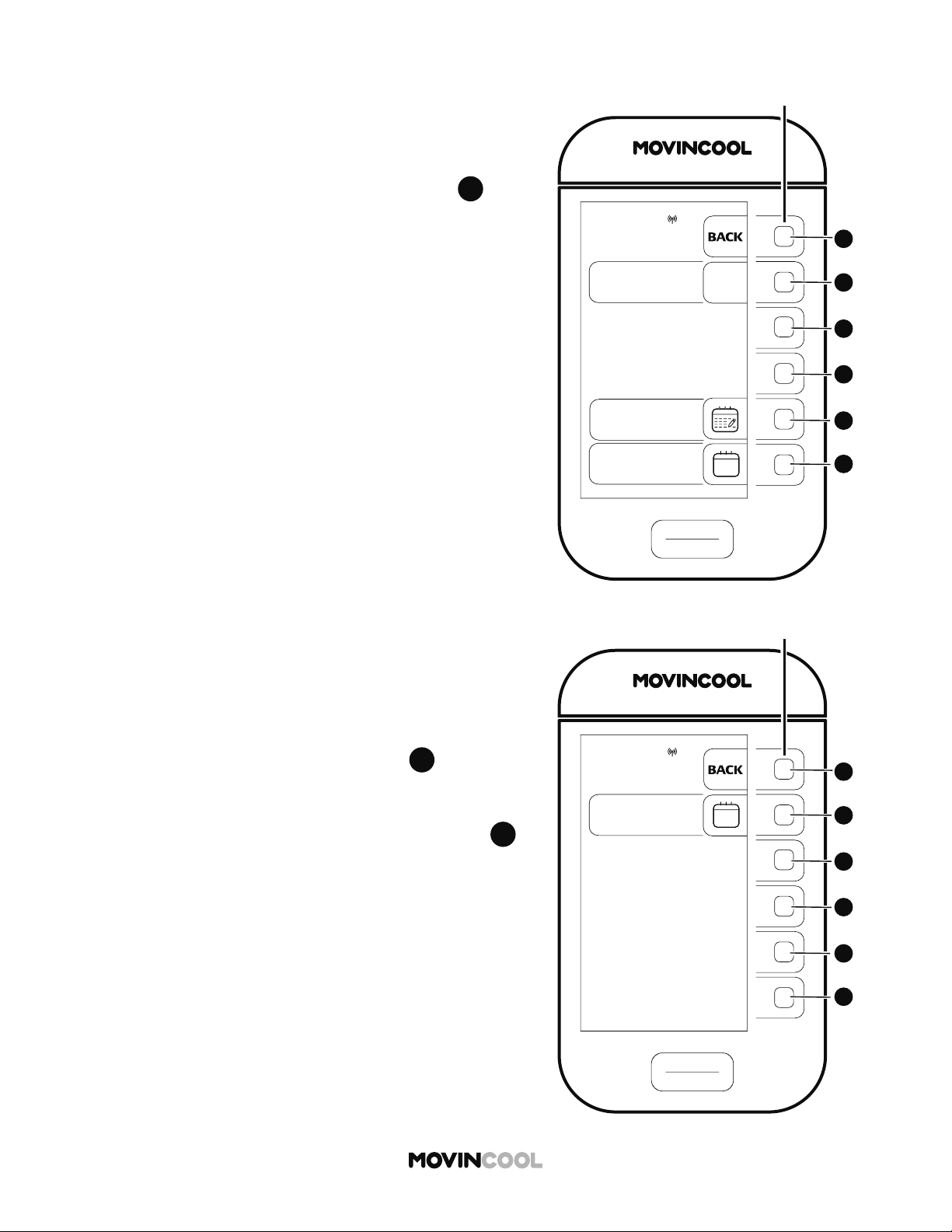
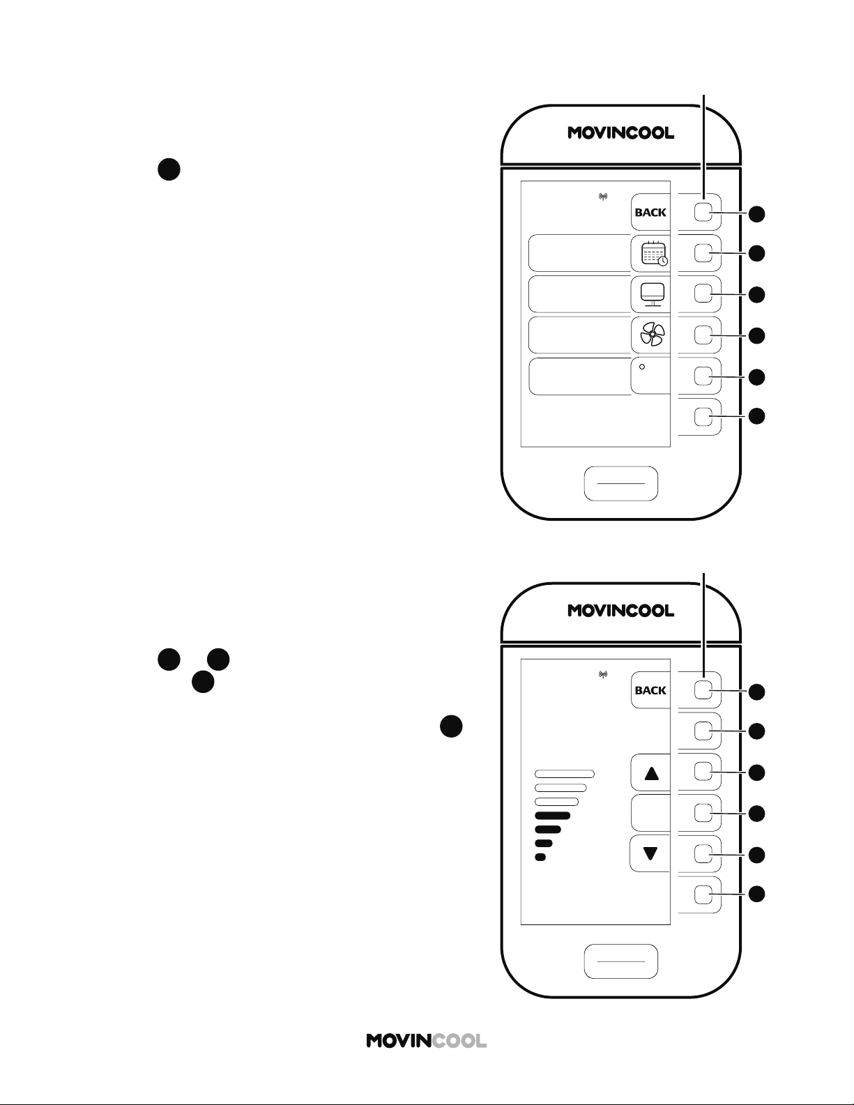
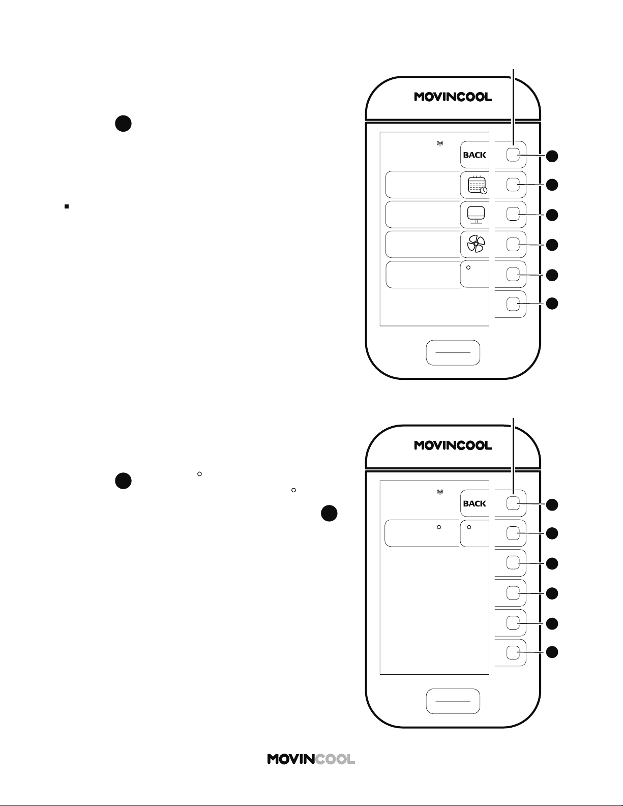
MODE SCREEN
HOME > MODE
Note:
If no bu on is pressed for 30 seconds, the screen automatically returns to the HOME screen.
COOL MODE icon
This icon is displayed on the HOME screen
during COOL MODE operation.
FAN MODE icon
This icon is displayed on the HOME screen
during FAN ONLY MODE operation.
SCHEDULE MODE icon
Press the adjacent bu on to go to
the SCHEDULE screen.
- Starting Schedule Mode Operation
- Stopping Schedule Mode Operation
- Se ing/Editing/Viewing Schedule
- Clearing Schedule
AUTO MODE icon
This icon is displayed on the HOME screen
during AUTO MODE operation.
HEAT MODE icon
This icon is displayed on the HOME screen
during HEAT MODE operation.
START
STOP
BACK
COOL
FAN
SCHEDULE
MODE
MON
12:00 PM
HEAT
AUTO
A
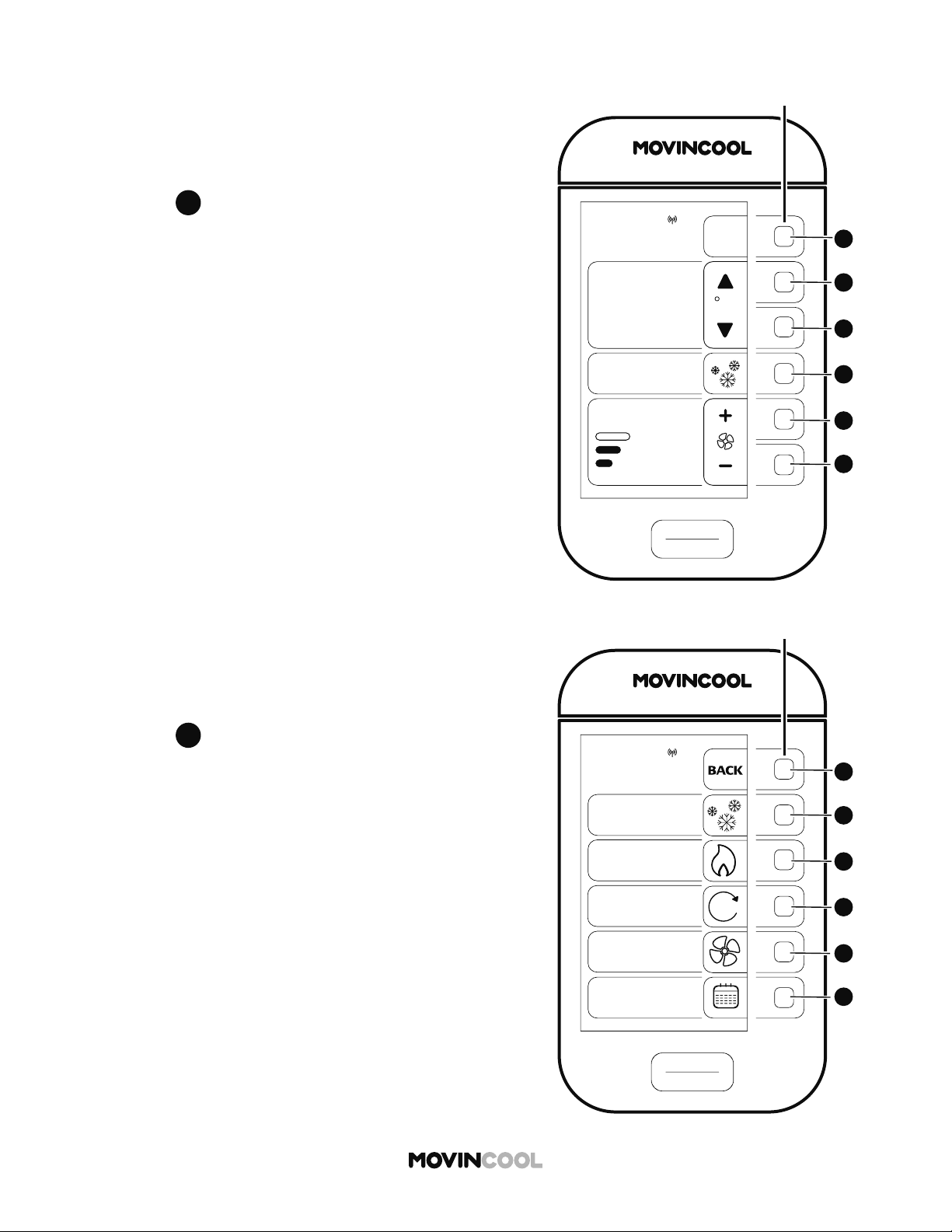
15
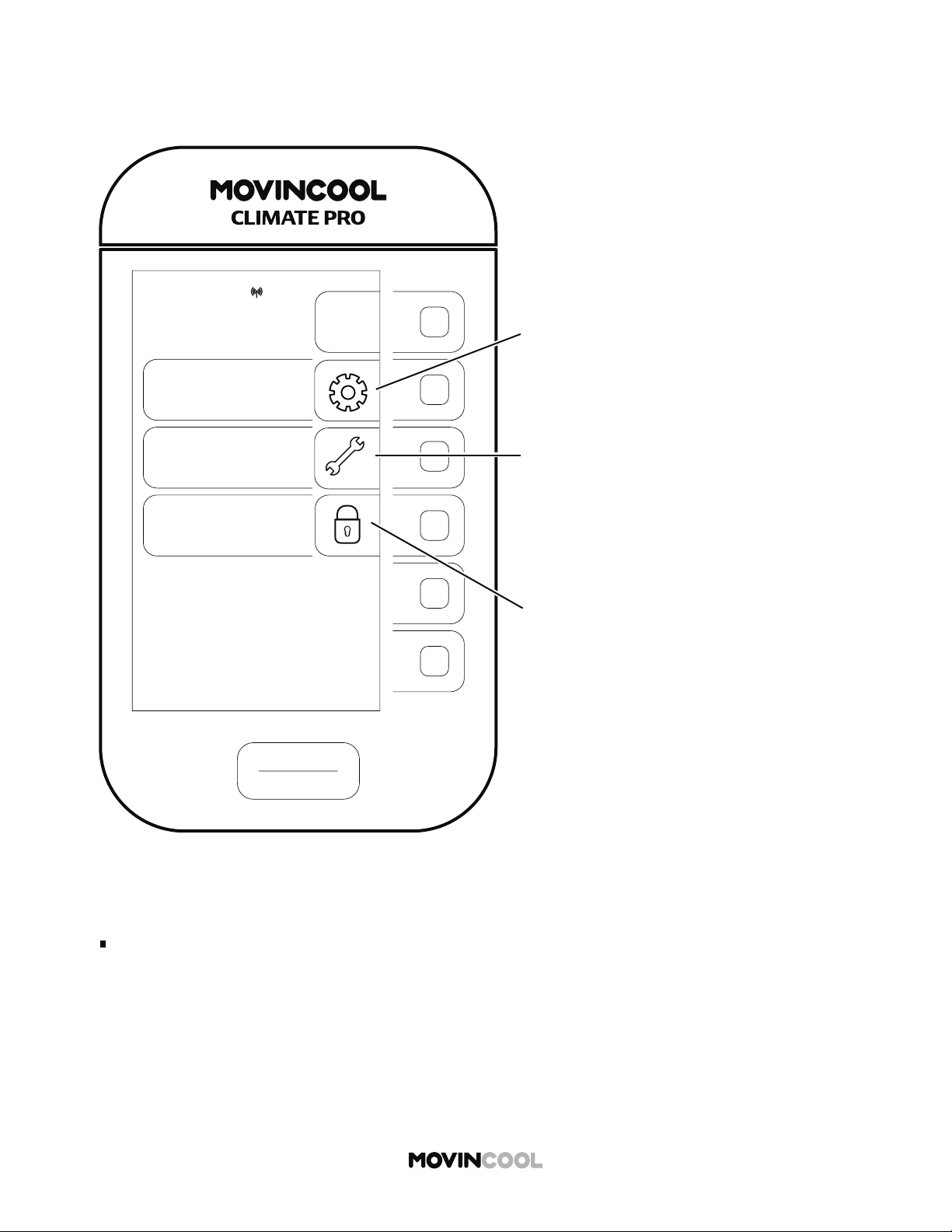
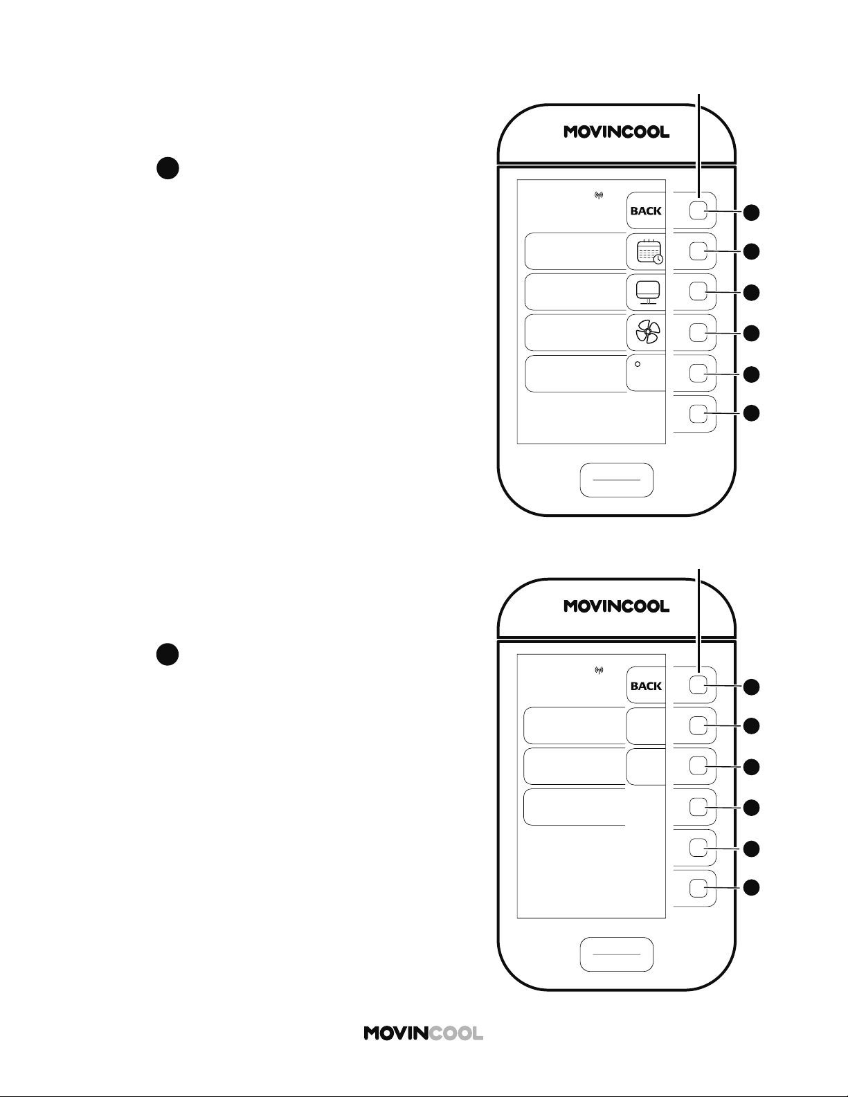
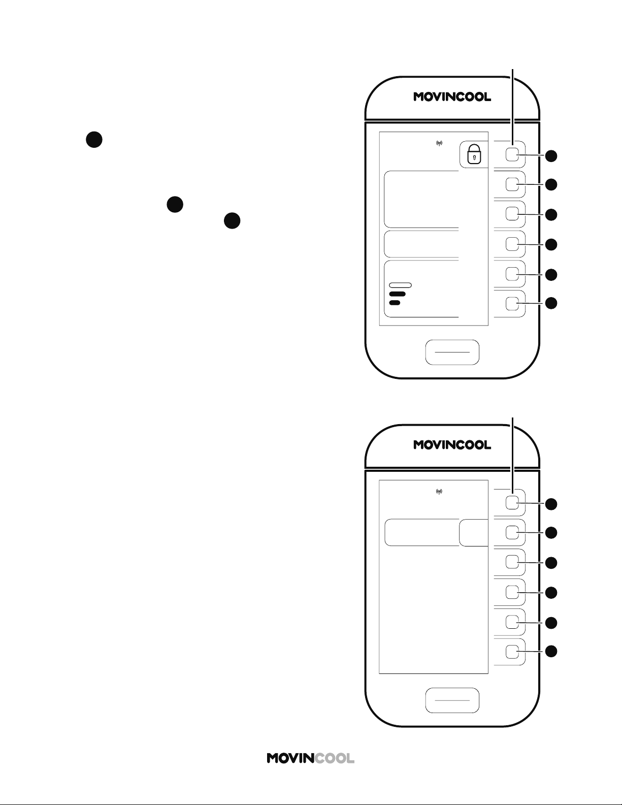
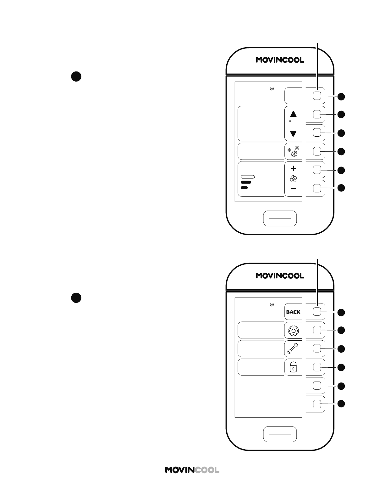
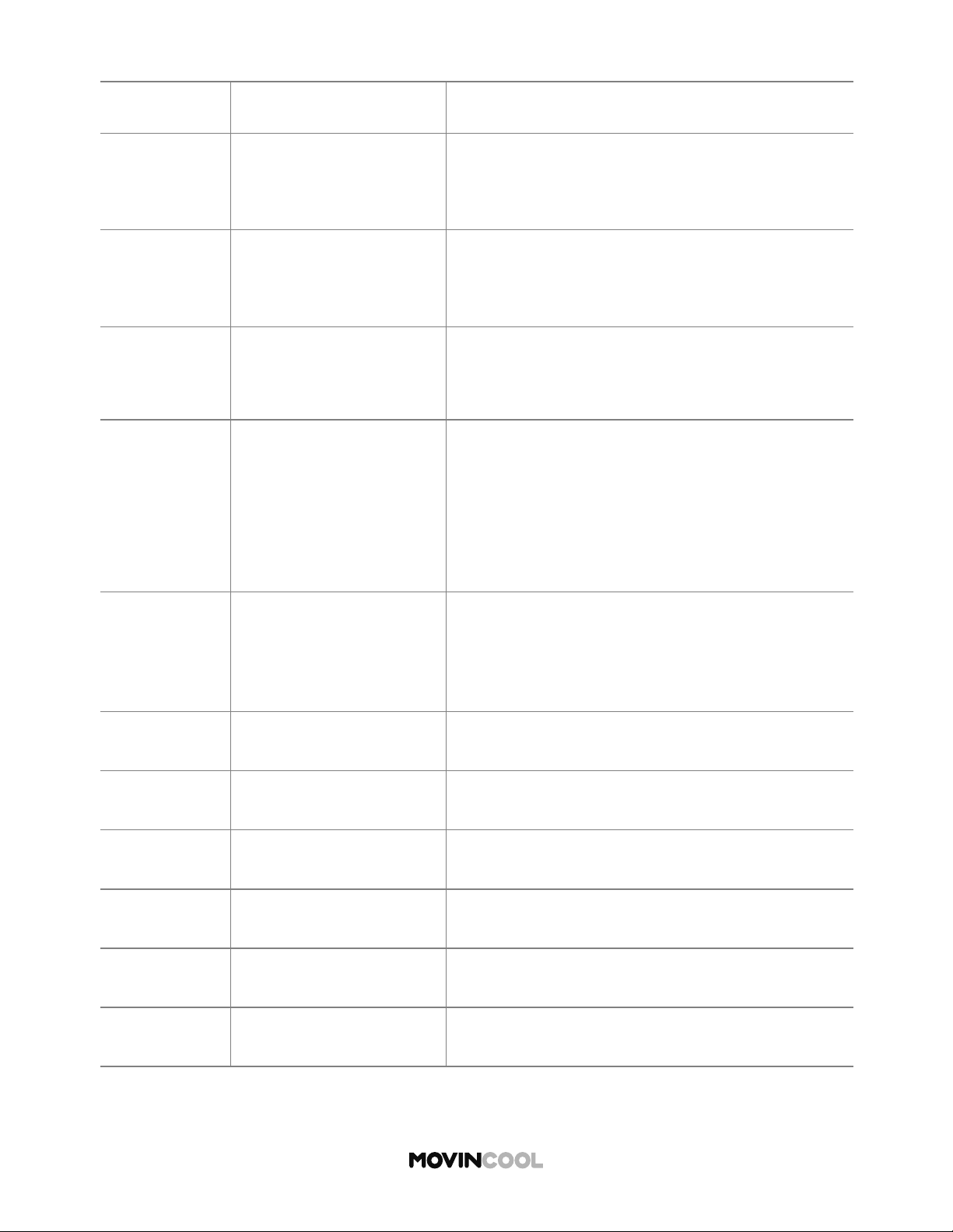
MENU SCREEN
HOME > MENU
Note:
If no bu on is pressed for 30 seconds, the screen automatically returns to the HOME screen.
START
STOP
MENU
BACK
SETTING
SERVICES
KEY LOCK
MON
12:00 PM
SETTING icon
Press the adjacent bu on to go to
the SETTING screen.
(DAY & TIME/DISPLAY/FAN MODE/
TEMP SCALE)
SERVICES icon
Press the adjacent bu on to go to the
SERVICES screen.
Machine information can be displayed:
- Machine status
- Machine records
KEY LOCK icon
Press the adjacent bu on to lock
all bu ons.

16
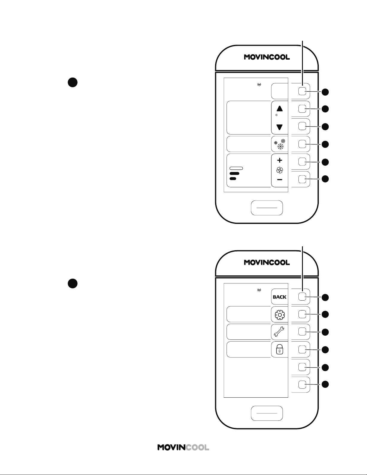
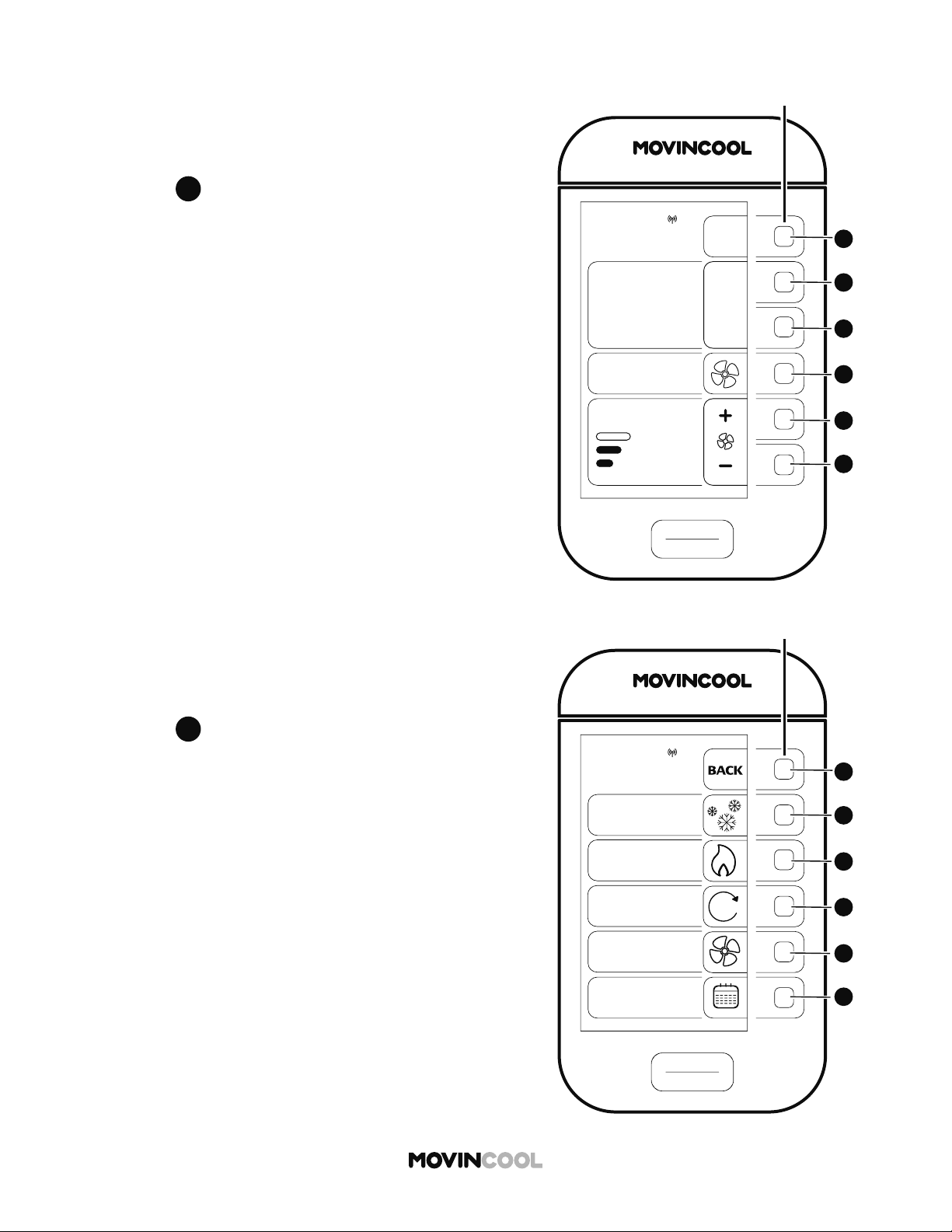
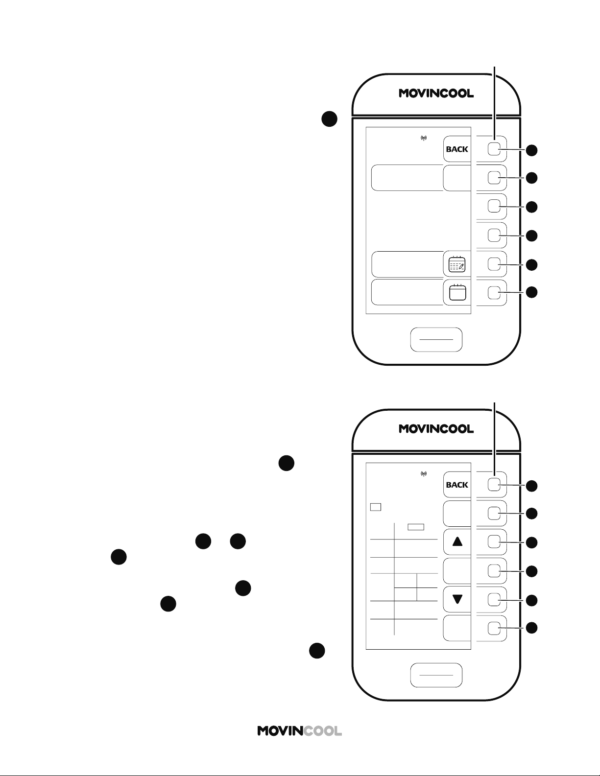
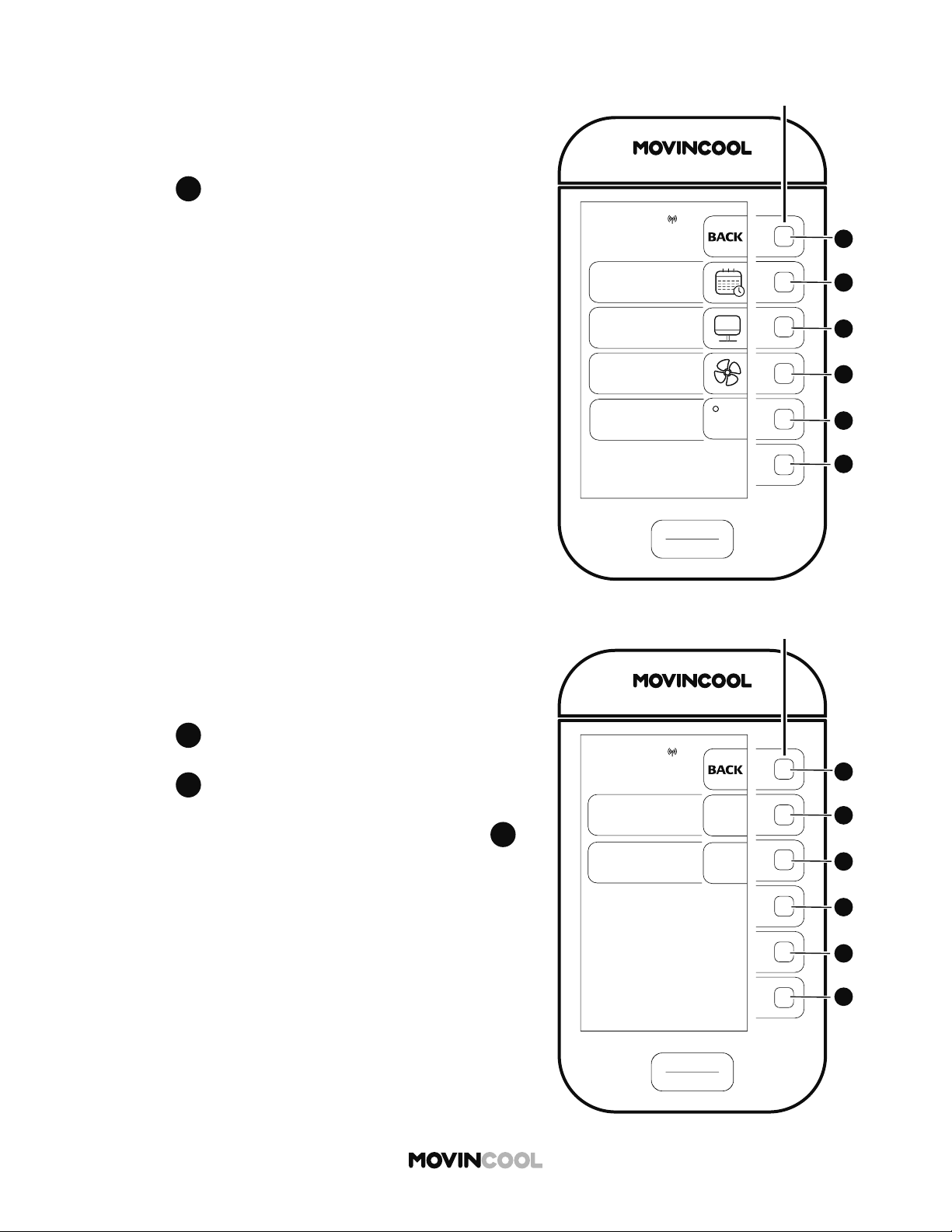
SETTING SCREEN
HOME > MENU > SETTING
Note:
TEMP SCALE is only displayed while the unit is idle.
If no bu on is pressed for 30 seconds, the screen automatically returns to the HOME screen.
SETTING
DAY & TIME
DISPLAY
FAN MODE
TEMP SCALE
F
t
t
t
START
STOP
MON
12:00 PM
BACK
DAY & TIME icon
Press the adjacent bu on to go to
the DAY & TIME screen.
- Daylight saving (ON/OFF)
- Select time zone
- Auto adjust (ON/OFF)
- Clock se ing
DISPLAY icon
Press the adjacent bu on to go to
the DISPLAY screen for adjusting
LCD brightness.
FAN MODE icon
Press the adjacent bu on to go to
the FAN MODE screen.
(ON/AUTO)
TEMP SCALE icon
Press the adjacent bu on to
change temperature scale.
(°F/°C)
17
PLACEMENT OF THE UNIT
INSTALLATION
Install the unit in a place which is strong enough to withstand the weight of the unit.
Incorrect installation may cause injury or the unit damage due to falling.
1. Unlock the casters and move the unit to a flat, level surface and then set the casters back
to the locked position.
*1
Approximate weight when the drain tank is full of water
MODEL UNIT WEIGHT *
1
Climate Pro D12 214 lb (97 kg)
Climate Pro D18 231 lb (105 kg)
Unlocked
Locked
2. Ensure the air inlets and outlets are not blocked. Keep a minimum clearance of 24 inches
(610 mm) from walls or other objects.
3. Unit weight table for 3 models
CAUTION
WARNING
Installation and electrical work must be performed by qualified electrical personnel.
Incorrect installation and/or electrical work may cause fire, electric shock, injury,
malfunction or water leaks.
To avoid explosion or fire:
Do not install the unit in a place where flammable gas may generate, flow, gather or leak.
Do not install the unit in a place where conductive dust or oil is floating.
18
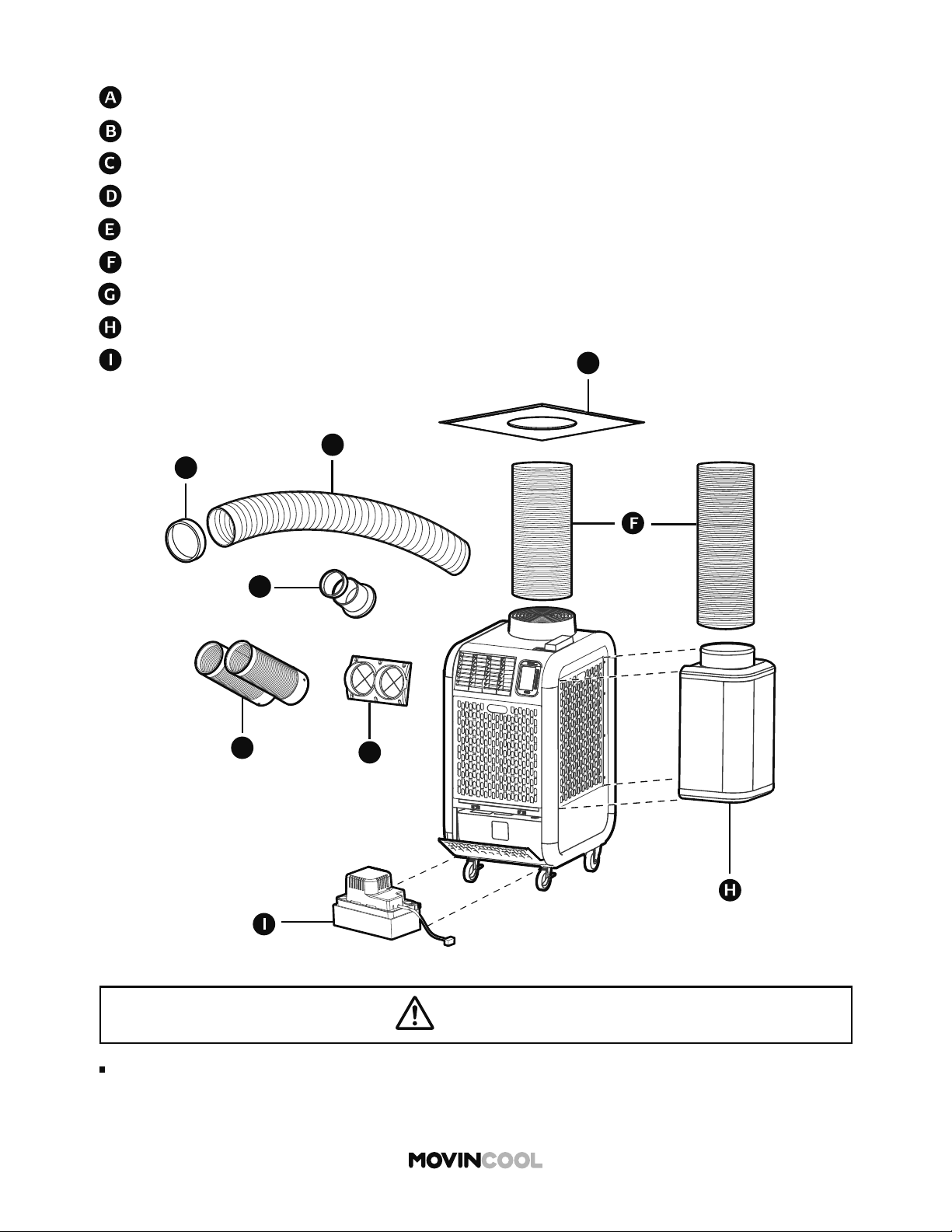
ACCESSORIES
Nozzle Adapter Kit
Cold Air Extension Duct
Self-Supported Duct
Outdoor Heat Exchanger Plenum
Nozzle Kit
Trim Ring
Ceiling Tile
Condensate Pump Kit
WARNING
Cold Air Flange Kit
A
B
C
D
E
G
Use only official accessories and consult your MovinCool dealer or qualified technician
for installing accessories to the unit. Non-genuine accessories or incomplete installation
may cause fire, electric shock or water leaks.
19
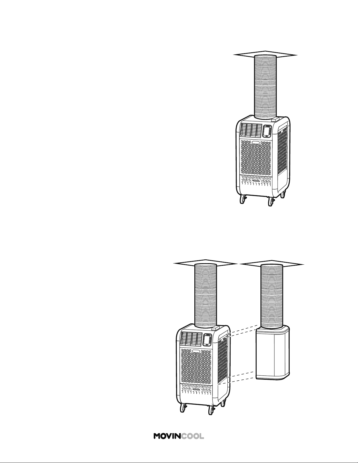
TYPICAL INSTALLATION OPTIONS
Option 1:
No negative air pressure in the room
Operating condition:
COOL mode: 65°F to 95°F, 50%RH
HEAT mode: 40°F to 80°F, 50%RH
Option 2:
Negative air pressure in the room
Operating condition:
COOL mode: 65°F to 95°F, 50%RH
HEAT mode:
Indoor Heat Exchanger:
40°F to 80°F, 50%RH
Outdoor Heat Exchanger:
24°F to 80°F, 50%RH
20
PLUGGING IN THE UNIT
Check the power supply outlet rating, recommended fuse size, and NEMA plug confi guration below.
MODEL
MINIMUM POWER SUPPLY RATING RECOMMENDED FUSE SIZE
NEMA PLUG
CONFIGURATION
Climate Pro D12 115V, 1 phase, 60 Hz, 15A 15A maximum 5-15
Climate Pro D18 115V, 1 phase, 60 Hz, 20A 20A maximum 5-20
WARNING
Insert the power plug properly into the outlet. Incomplete insertion may cause fi re or electric
shock.
To avoid fi re, electric shock or malfunction:
Do not connect or disconnect the power plug with wet or oily hands.
Do not turn the unit on or o by connecting or disconnecting the power plug.
To avoid generation of heat, fi re or electric shock:
Do not use an extension cord or multi-socket plug.
Do not heat, pull, wind, bundle or place heavy objects on the power cord.
Do not use damaged power cord/plug or modify the cord/plug.
Qualifi ed personnel must replace the damaged power cords with one of the same LCDI
(Leakage Current Detection Interrupter) cord, obtainable from the AC manufacturer.
Incorrect replacements may cause fi re, electric shock, injury or malfunction.
Always use fuses with correct capacity. Using copper or other wire may result in fi re or
malfunction.
21
LCDI (Leakage Current Detection Interrupter) POWER CORD
Note:
The LCDI is a non-serviceable device. Damage caused by attempting to do the repair
yourself will void the warranty.
The unit is equipped with LCDI to monitor leakage current. Read the instructions printed on the
device for proper use and handling. The conductors inside the cord are surrounded by shields, which
are not grounded. Check the cord for damage regularly. If the device trips, fi nd the cause and correct
the fault before operating the unit.
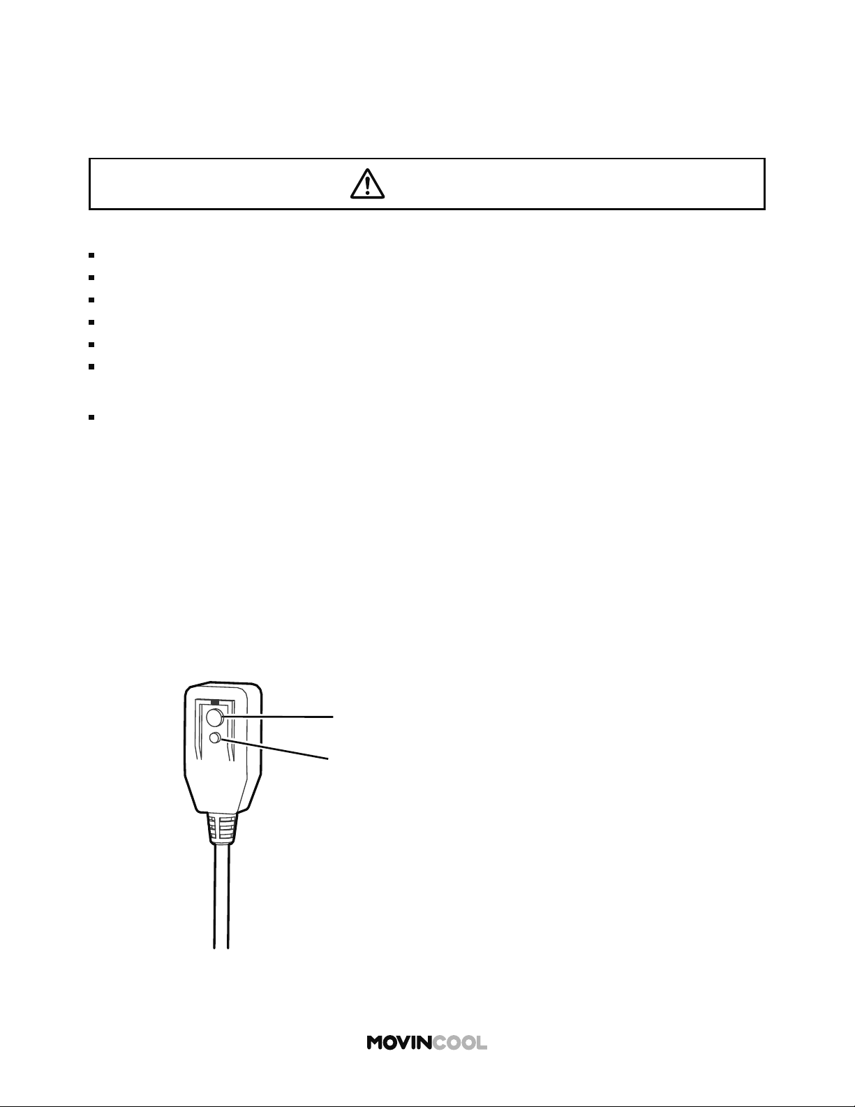
TEST PROCEDURE
Follow the instructions to ensure that LCDI power cord works properly.
1. Plug the power cord into a grounded power outlet.
2. If the green power light is not on, press RESET bu on once.
The light should come on.
3. Press TEST bu on once, the power light should go o .
4. Press RESET bu on once again for use. The power light should come on.
5. If this test fails, do not use this device. Contact a qualifi ed technician.
Reset Buon
Test Buon
WARNING
To avoid fire, electric shock or malfunction:
Do not attempt to open the device.
Do not immerse in water.
Do not remove the ground prong.
Do not use the device beyond the recommended voltage.
Do not use the device if the shields become exposed.
Do not repeatedly push TEST and/or RESET buttons.
22
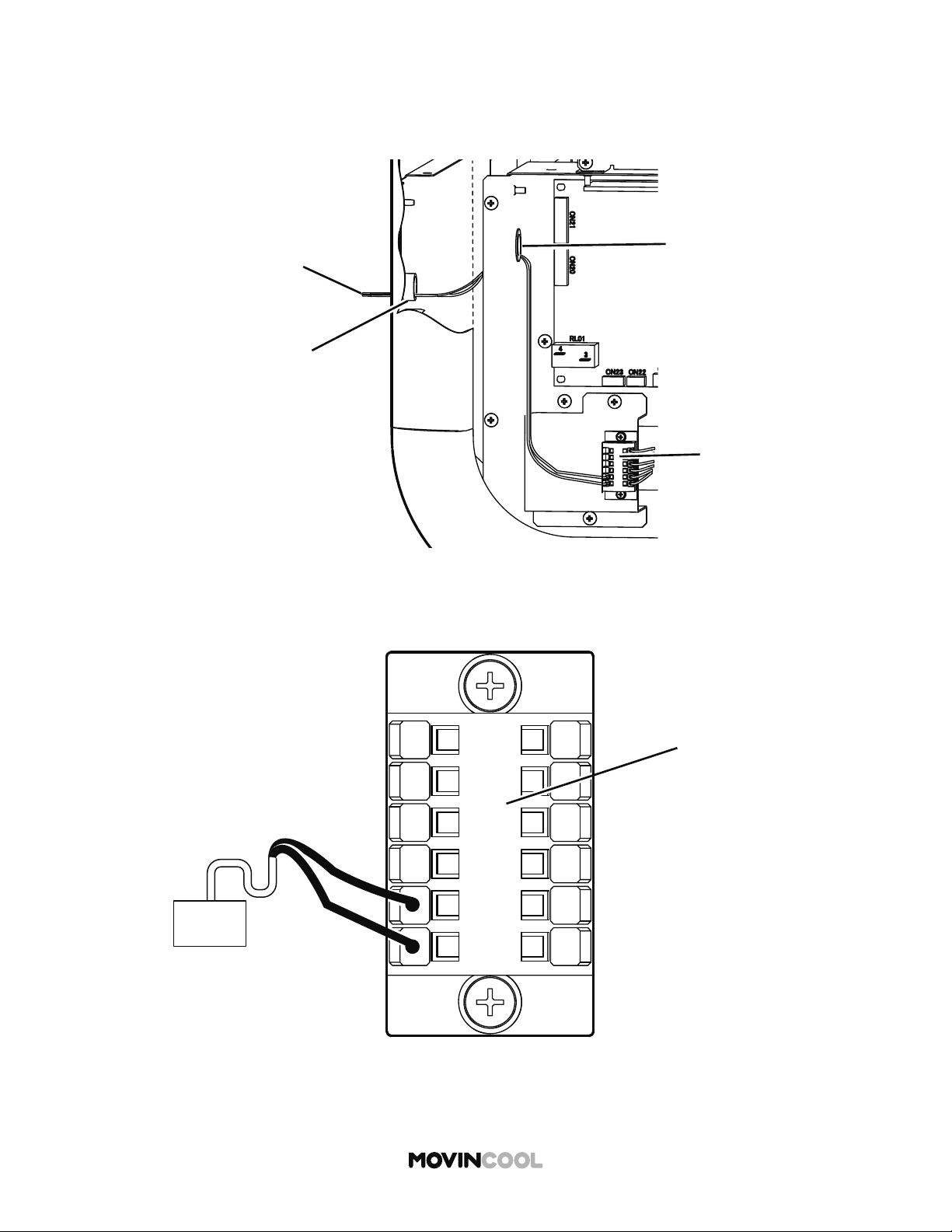
EXTERNAL WARNING DEVICE CONNECTION
1. Turn the unit o and unplug the power cord.
2. Loosen the bo om two (2) screws and take out
the other seven (7) screws. Move the service
panel upward and remove it from the side of
the unit.
The controller has a warning signal output relay which can indicate failure of the unit with external
warning devices such as alarm speaker or light indicators.
Relay type: Form C, normal open dry contact
Relay output contactor rating: 2 A at 30 V (DC/AC) or less (resistive load)
Take out screws (7)
Service Panel
Loosen screws (2)
Loosen screw (1)
Lower Rear Panel
Cap (a hole for wires)
Take out screws (7)
Upper Rear Panel
3. Loosen the center bo om screw and take out
the other seven (7) screws. Move the upper rear
panel upward and remove it.
4. Squeeze the inner latch and push out the cap
from inside the lower rear panel.
WARNING
Installation and electrical work must be performed in accordance with national wiring
regulations by qualified personnel. Incorrect installation may cause fire, electric shock,
injury, malfunction or water leaks.
Disconnect power before installation. Beware that some residual voltage may remain in the
unit a er the power is disconnected. There is a risk of electric shock.
23
5. Insert the warning signal wires through the hole in the rear panel and then through the hole in
the control box.
Recommended wire size: 16 AWG - 22 AWG
EXTERNAL WARNING DEVICE CONNECTION
Hole in the Rear Panel
Route of Signal Wires
Terminal Block
Hole in the Control Box
OS-1
OS-2
FA-2
FA-1
AL-1
AL-2
Warning Device
Terminal Block
6. Connect the warning signal wires to the terminals OS-1 and OS-2 as shown in the figure.
7. Reinstall the panels.

24
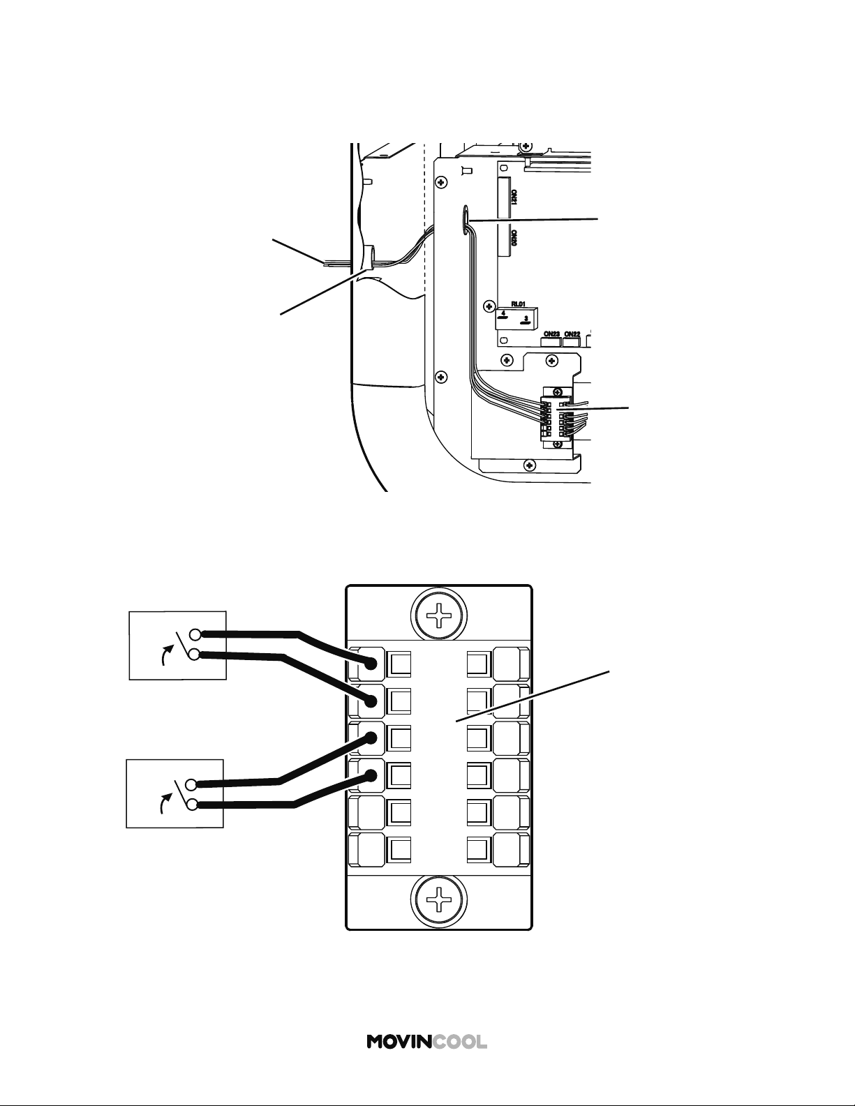
EXTERNAL ALARM DEVICE CONNECTION
1. Turn the unit o and unplug the power cord.
2. Loosen the bo om two (2) screws and take out
the other seven (7) screws. Move the service
panel upward and remove it from the side of
the unit.
The terminal block has two sets of input signal terminals for external alarm devices such as a fi re
alarm. The terminals should only be connected to a closed or an open dry contact. When receiving
the signals from the external alarm devices, the unit turns itself o and cannot be turned back on
until it has been reset.
Take out screws (7)
Service Panel
Loosen screws (2)
Loosen screw (1)
Lower Rear Panel
Cap (a hole for wires)
Take out screws (7)
Upper Rear Panel
3. Loosen the center bo om screw and take out
the other seven (7) screws. Move the upper rear
panel upward and remove it.
4. Squeeze the inner latch and push out the cap
from inside the lower rear panel.
WARNING
Installation and electrical work must be performed in accordance with national wiring
regulations by qualified personnel. Incorrect installation may cause fire, electric shock,
injury, malfunction or water leaks.
Disconnect power before installation. Beware that some residual voltage may remain in the
unit after the power is disconnected. There is a risk of electric shock.
25
5. Insert the alarm signal wires through the hole in the rear panel and then through the hole in
the control box.
Recommended wire size: 16 AWG - 22 AWG
EXTERNAL ALARM DEVICE CONNECTION
Hole in the Rear Panel
Route of Signal Wires
Terminal Block
Hole in the Control Box
OS-1
OS-2
FA-2
FA-1
AL-1
AL-2
Alarm Device 1
Alarm Device 2
Terminal Block
6. Connect the alarm signal wires to terminal AL-1 and AL-2 and/or FA-1 and FA-2 as shown
in the figure.
7. Reinstall the panels.
26
PRIVACY DISCLOSURE SCREEN
INITIAL SETTINGS
When the unit is connected to the power supply for the fi rst
time, PRIVACY DISCLOSURE screen is displayed.
Read the on-screen message.
Press
F
F
The HOME screen will be displayed.
START
STOP
A
A
B
B
C
C
D
D
E
E
F
F
CLIMATE PRO
Multi-function buons
PRIVACY DISCLOSURE
TRACKING OF OPERATION
DATA & LOCATION
This unit is equipped with a module
that collects and transmits the Unit’s
operation data and geolocation info
for analytical purposes. We may
share data with the supplier or
owner of the Unit or with a third
party processor in U.S. By reading
this disclosure and using this Unit,
you are consenting to our use and
sharing of the data. If you do not
consent to our use of this module or
do not want us to share such data,
the module can be disabled or you
can “Opt Out” of sharing by
contacting us. Please refer to
Operation Manual or visit us at
www.movincool.com
for further information.
NEXT

START
STOP
A
A
B
B
C
C
D
D
E
E
F
F
CLIMATE PRO
Multi-function buons
COOL
75
MODE
SET TEMP
MENU
MON 12:00 PM
F
86
ROOM
TEMP
AUTO
FAN SPEED
MENU
SETTING
SERVICES
KEY LOCK
MON
12:00 PM
START
STOP
A
A
B
B
C
C
D
D
E
E
F
F
CLIMATE PRO
Multi-function buons
27
SELECTING TIME ZONE
Prior to operation, select your time zone.
The default time zone is PST (UTC-08:00).
1. Press
A
A
on the HOME screen.
2. Press
B
B
to select SETTING on the MENU screen.

SETTING
DAY & TIME
DISPLAY
FAN MODE
TEMP SCALE
F
MON
12:00 PM
START
STOP
A
A
B
B
C
C
D
D
E
E
F
F
CLIMATE PRO
Multi-function buons
START
STOP
A
A
B
B
C
C
D
D
E
E
F
F
CLIMATE PRO
Multi-function buons
DAY & TIME
DAYLIGHT
SAVING
OFF
DAY & TIME ARE
SYNCHRONIZED
WITH GNSS CLOCK
ON
AUTO ADJUST
ON
OFF
SELECT TIME
ZONE
MON
12:00 PM
28
SELECTING TIME ZONE
3. Press
B
B
to select DAY & TIME on the SETTING screen.
4. Press
D
D
to go to SELECT TIME ZONE screen.
TIME ZONE
SELECTION
EST (UTC-05:00)
CST (UTC-06:00)
MST (UTC-07:00)
PST (UTC-08:00)
AKST (UTC-09:00)
HST (UTC-10:00)
ENTER
MON
12:00 PM
START
STOP
A
A
B
B
C
C
D
D
E
E
F
F
CLIMATE PRO
Multi-function buons
29
SELECTING TIME ZONE
5. Select your time zone by pressing
C
C
or
E
E
and
then press
D
D
to save.
The screen returns to the previous screen.
If you wish to return to the HOME screen, press
A
A
repeatedly until the HOME screen is displayed.

START
STOP
A
A
B
B
C
C
D
D
E
E
F
F
CLIMATE PRO
Multi-function buons
COOL
75
MODE
SET TEMP
MENU
MON 12:00 PM
F
86
ROOM
TEMP
AUTO
FAN SPEED
MENU
SETTING
SERVICES
KEY LOCK
MON
12:00 PM
START
STOP
A
A
B
B
C
C
D
D
E
E
F
F
CLIMATE PRO
Multi-function buons
30
SETTING DAYLIGHT SAVINGS
When daylight savings start or end, set DAYLIGHT
SAVINGS TIME.
1. Press
A
A
on the HOME screen.
2. Press
B
B
to select SETTING on the MENU screen.
SETTING
DAY & TIME
DISPLAY
FAN MODE
TEMP SCALE
F
MON
12:00 PM
START
STOP
A
A
B
B
C
C
D
D
E
E
F
F
CLIMATE PRO
Multi-function buons
START
STOP
A
A
B
B
C
C
D
D
E
E
F
F
CLIMATE PRO
Multi-function buons
DAY & TIME
DAYLIGHT
SAVING
OFF
DAY & TIME ARE
SYNCHRONIZED
WITH GNSS CLOCK
ON
AUTO ADJUST
ON
OFF
SELECT TIME
ZONE
MON
12:00 PM
31
SETTING DAYLIGHT SAVINGS
3. Press
B
B
to select DAY & TIME on the SETTING
screen.
4. Press
B
B
to switch to ON.
The default se ing of the DAYLIGHT SAVINGS is OFF.
If you wish to return to the HOME screen, press
A
A
repeatedly until the HOME screen is displayed.
START
STOP
A
A
B
B
C
C
D
D
E
E
F
F
CLIMATE PRO
Multi-function buons
COOL
75
MODE
SET TEMP
MENU
MON 12:00 PM
F
86
ROOM
TEMP
AUTO
FAN SPEED
MENU
SETTING
SERVICES
KEY LOCK
MON
12:00 PM
START
STOP
A
A
B
B
C
C
D
D
E
E
F
F
CLIMATE PRO
Multi-function buons
32
CLOCK SETTING
Day and time are synchronized with GNSS (Global
Navigation Satellite System) clock.
If the time is not adjusted automatically, set the clock
manually.
1. Press
A
A
on the HOME screen.
2. Press
B
B
to select SETTING on the MENU screen.
SETTING
DAY & TIME
DISPLAY
FAN MODE
TEMP SCALE
F
MON
12:00 PM
START
STOP
A
A
B
B
C
C
D
D
E
E
F
F
CLIMATE PRO
Multi-function buons
START
STOP
A
A
B
B
C
C
D
D
E
E
F
F
CLIMATE PRO
Multi-function buons
DAY & TIME
DAYLIGHT
SAVING
OFF
DAY & TIME ARE
SYNCHRONIZED
WITH GNSS CLOCK
ON
AUTO ADJUST
ON
OFF
SELECT TIME
ZONE
MON
12:00 PM
33
CLOCK SETTING
3. Press
B
B
to select DAY & TIME on the SETTING screen.
4. Press
C
C
to switch to AUTO ADJUST OFF.
The default se ing of the AUTO ADJUST is ON.
START
STOP
A
A
B
B
C
C
D
D
E
E
F
F
CLIMATE PRO
Multi-function buons
DAYLIGHT
SAVING
OFF
ON
AUTO ADJUST
OFF
ON
CLOCK SETTING
MON
12:00 PM
DAY & TIME
START
STOP
A
A
B
B
C
C
D
D
E
E
F
F
CLIMATE PRO
Multi-function buons
CLOCK SETTING
MON 8:00 AM
ENTER
MON
12:00 PM
NEXT
34
CLOCK SETTING
5. CLOCK SETTING is shown on the DAY & TIME screen.
Press
D
D
to go to CLOCK SETTING screen.
6. Select day of the week by pressing
C
C
or
E
E
and
then press
D
D
7. Follow the same procedure to set hour and minute.
8. Press
F
F
to save the day and time. The screen returns
to the previous screen.
If you wish to return to the HOME screen, press
A
A
repeatedly until the HOME screen is displayed.
Tape
Tape
Drain Tank
Packing Foam Sheet
Packing Foam Sheet
Drain Tank
35
REMOVING SECURING TAPES AND SHEET
Before starting operation, remove the tapes securing the drain tank, and then take out the
packing foam sheet covering the tank. Return the tank to the unit.
CAUTION
Do not operate without the tank. Ensure that the tank is correctly installed.
Water leaks from the unit may cause property damage or injury due to wet floor.
START
STOP
A
A
B
B
C
C
D
D
E
E
F
F
CLIMATE PRO
Multi-function buons
COOL IDLE
75
MODE
SET TEMP
MENU
12:00 PM
F
86
AUTO
FAN SPEED
MON
ROOM
TEMP
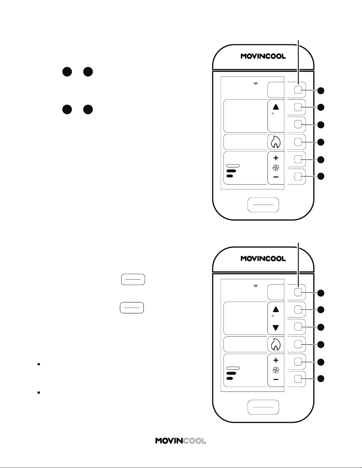
36
The set temperature range is 65°F - 90°F (18°C - 32°C)
1. Press
D
D
on the HOME screen.
COOL MODE
OPERATION
2. Press
B
B
to select COOL on the MODE screen.
START
STOP
A
A
B
B
C
C
D
D
E
E
F
F
CLIMATE PRO
Multi-function buons
MON
12:00 PM
MODE
COOL
FAN
SCHEDULE
HEAT
AUTO
A

START
STOP
A
A
B
B
C
C
D
D
E
E
F
F
CLIMATE PRO
Multi-function buons
COOL IDLE
65
MODE
SET TEMP
MENU
MIN
MON
12:00 PM
F
86
ROOM
TEMP
AUTO
FAN SPEED
START
STOP
A
A
B
B
C
C
D
D
E
E
F
F
CLIMATE PRO
Multi-function buons
COOL
75
MODE
SET TEMP
MENU
MON
12:00 PM
F
86
ROOM
TEMP
AUTO
FAN SPEED
37
3. Use
B
B
or
C
C
to change the set temperature.
If the set temperature reaches the minimum or
maximum value, MIN or MAX is displayed.
4. Use
E
E
or
F
F
to change fan speed (HI, MID, LO).
COOL MODE
5. To start operation, press
START
STOP
on the HOME
screen.
6. To stop operation, press
START
STOP
on the HOME screen.
Note:
"COOL IDLE" mode is displayed on the HOME screen
when COOL mode is not active.
START/STOP bu on
"START" is active only on the HOME screen.
"STOP" is active on all screens.

START
STOP
A
A
B
B
C
C
D
D
E
E
F
F
CLIMATE PRO
Multi-function buons
HEAT IDLE
78
MODE
SET TEMP
MENU
12:00 PM
F
92
AUTO
FAN SPEED
MON
ROOM
TEMP
38
The set temperature range is 55°F - 80°F (13°C - 27°C)
1. Press
D
D
on the HOME screen.
HEAT MODE
2. Press
C
C
to select HEAT on the MODE screen.
START
STOP
A
A
B
B
C
C
D
D
E
E
F
F
CLIMATE PRO
Multi-function buons
MON
12:00 PM
MODE
COOL
FAN
SCHEDULE
HEAT
AUTO
A
39
HEAT MODE
5. To start operation, press
START
STOP
on the HOME
screen.
6. To stop operation, press
START
STOP
on the HOME
screen.
Note:
"HEAT IDLE" mode is displayed on the HOME screen
when HEAT mode is not active.
START/STOP bu on
"START" is active only on the HOME screen.
"STOP" is active on all screens.
START
STOP
A
A
B
B
C
C
D
D
E
E
F
F
CLIMATE PRO
Multi-function buons
HEAT IDLE
55
MODE
SET TEMP
MENU
12:00 PM
F
92
AUTO
FAN SPEED
MON
ROOM
TEMP
MIN
START
STOP
A
A
B
B
C
C
D
D
E
E
F
F
CLIMATE PRO
Multi-function buons
HEAT
78
MODE
SET TEMP
MENU
12:00 PM
F
92
AUTO
FAN SPEED
MON
ROOM
TEMP
3. Use
B
B
or
C
C
to change the set temperature.
If the set temperature reaches the minimum or
maximum value, MIN or MAX is displayed.
4. Use
E
E
or
F
F
to change fan speed (HI, MID, LO).
START
STOP
A
A
B
B
C
C
D
D
E
E
F
F
CLIMATE PRO
Multi-function buons
AUTO IDLE
75/67
MODE
SET TEMP
MENU
12:00 PM
F
86
AUTO
FAN SPEED
MON
ROOM
TEMP
A
40
The system switches to COOL or HEAT mode automatically
based on the room and set temperatures.
The set temperatures in COOL and HEAT modes are
displayed on the same screen.
1. Press
D
D
on the HOME screen.
AUTO MODE
2. Press
D
D
to select AUTO on the MODE screen.
START
STOP
A
A
B
B
C
C
D
D
E
E
F
F
CLIMATE PRO
Multi-function buons
MON
12:00 PM
MODE
COOL
FAN
SCHEDULE
HEAT
AUTO
A
75/67
SET TEMP
COOL HEAT
41
3. The set temperatures of COOL and HEAT can be
changed simultaneously by pressing
B
B
or
C
C
until reaching the minimum or maximum value.
If the di erence between set temperatures of COOL
and HEAT becomes less than 8 degrees, the COOL
set temperature is automatically adjusted to the
HEAT set temperature plus 8 degrees.
4. Use
E
E
or
F
F
to change fan speed (HI, MID, LO).
AUTO MODE
5. To start operation, press
START
STOP
on the HOME
screen.
6. To stop operation, press
START
STOP
on the HOME
screen.
Note:
"AUTO IDLE" mode is displayed on the HOME screen
when AUTO mode is not active.
START/STOP bu on
"START" is active only on the HOME screen.
"STOP" is active on all screens.
START
STOP
A
A
B
B
C
C
D
D
E
E
F
F
CLIMATE PRO
Multi-function buons
AUTO IDLE
75/67
MODE
SET TEMP
MENU
12:00 PM
F
86
AUTO
FAN SPEED
MON
ROOM
TEMP
A
START
STOP
A
A
B
B
C
C
D
D
E
E
F
F
CLIMATE PRO
Multi-function buons
AUTO COOL
75/67
MODE
SET TEMP
MENU
12:00 PM
F
86
AUTO
FAN SPEED
MON
ROOM
TEMP
A
START
STOP
A
A
B
B
C
C
D
D
E
E
F
F
CLIMATE PRO
Multi-function buons
FAN IDLE
MODE
MON
12:00 PM
86
ROOM
TEMP
MENU
FAN SPEED
42
1. Press
D
D
on the HOME screen.
FAN ONLY MODE
2. Press
E
E
to select FAN on the MODE screen.
START
STOP
A
A
B
B
C
C
D
D
E
E
F
F
CLIMATE PRO
Multi-function buons
MON
12:00 PM
MODE
COOL
FAN
SCHEDULE
HEAT
AUTO
A

43
3. Use
E
E
or
F
F
to change fan speed (HI, MID, LO).
FAN ONLY MODE
START
STOP
A
A
B
B
C
C
D
D
E
E
F
F
CLIMATE PRO
Multi-function buons
FAN IDLE
MODE
MON
12:00 PM
86
ROOM
TEMP
MENU
FAN SPEED
START
STOP
A
A
B
B
C
C
D
D
E
E
F
F
CLIMATE PRO
Multi-function buons
FA N
MODE
MON
12:00 PM
86
ROOM
TEMP
MENU
FAN SPEED
4. To start operation, press
START
STOP
on the HOME
screen.
5. To stop operation, press
START
STOP
on the HOME
screen.
Note:
"FAN IDLE" mode is displayed on the HOME screen
when FAN mode is not active.
START/STOP bu on
"START" is active only on the HOME screen.
"STOP" is active on all screens.

START
STOP
A
A
B
B
C
C
D
D
E
E
F
F
CLIMATE PRO
Multi-function buons
COOL
75
MODE
SET TEMP
MENU
MON 12:00 PM
F
86
ROOM
TEMP
AUTO
FAN SPEED
START
STOP
A
A
B
B
C
C
D
D
E
E
F
F
CLIMATE PRO
Multi-function buons
MON
12:00 PM
MODE
COOL
FAN
SCHEDULE
HEAT
AUTO
A
44
SCHEDULE MODE
1. Press
D
D
on the HOME screen.
2. Press
F
F
to select SCHEDULE on the MODE screen.
START
STOP
A
A
B
B
C
C
D
D
E
E
F
F
CLIMATE PRO
Multi-function buons
SCHEDULES
SCHEDULE:
OFF
ON
EDIT/VIEW
SCHEDULE
CLEAR
SCHEDULE
ALL KEY BUTTONS
WILL BE LOCKED
WHEN SCHEDULE
TURNS ON
MON
12:00 PM
45
STARTING SCHEDULE MODE OPERATION
1. Press
B
B
on the SCHEDULES screen to start
SCHEDULE MODE operation. A er 3 seconds, the
HOME screen will be displayed if no keys are pressed.
If you wish to cancel starting SCHEDULE MODE
operation in those 3 seconds, press
B
B
on the
screen below.
Note:
All key bu ons are locked during SCHEDULE MODE
operation.
START
STOP
A
A
B
B
C
C
D
D
E
E
F
F
CLIMATE PRO
Multi-function buons
SCHEDULES
SCHEDULE:
ON
OFF
MON
12:00 PM
START
STOP
A
A
B
B
C
C
D
D
E
E
F
F
CLIMATE PRO
Multi-function buons
SCHED. COOL
75
MODE
SET TEMP
MON
12:00 PM
86
ROOM
TEMP
AUTO
FAN SPEED
46
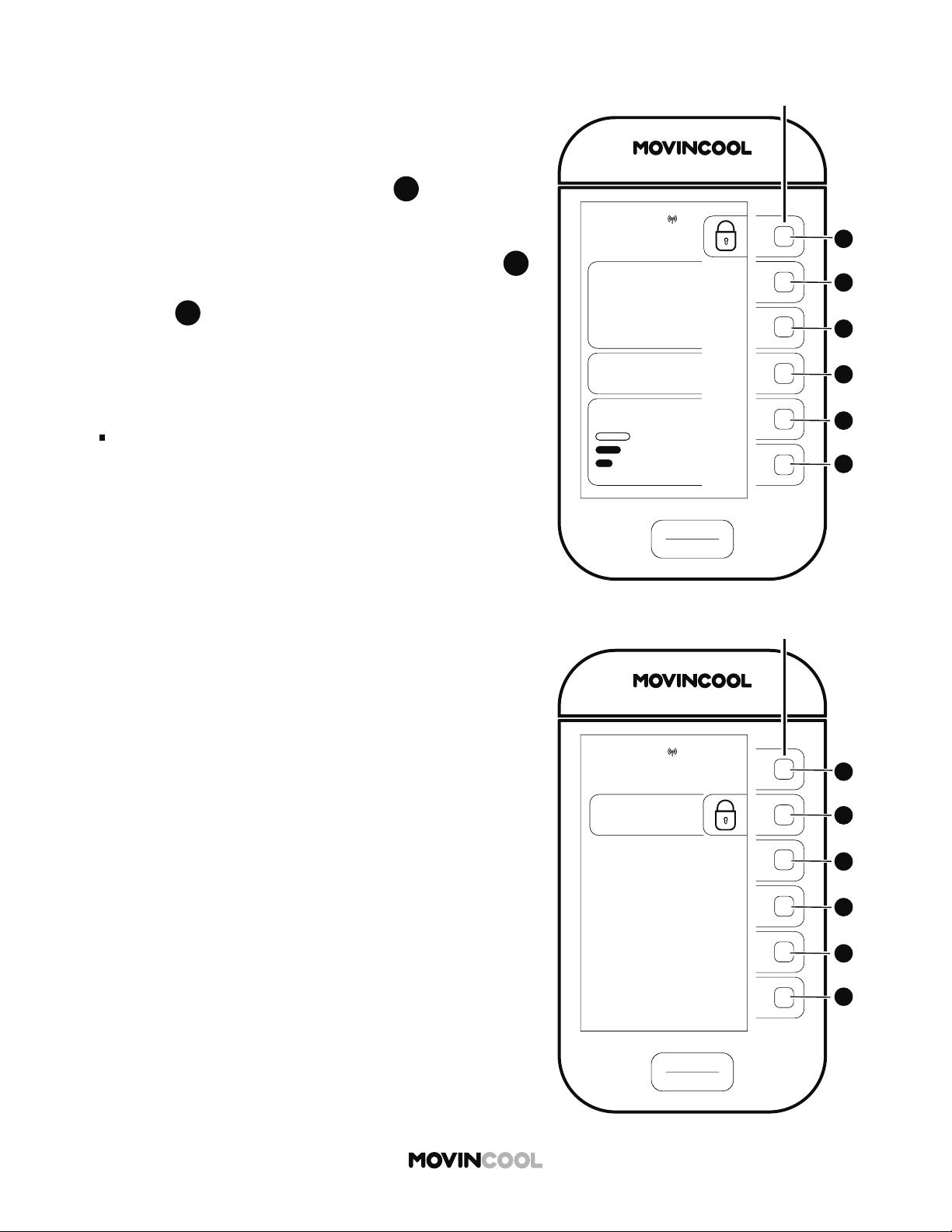
STARTING SCHEDULE MODE OPERATION
2. "SCHED. COOL" and (KEY LOCK icon) are displayed
on the HOME screen when SCHEDULE MODE operation
is running.
Note:
Refer to page 51 for se ing or editing SCHEDULE
MODE operation.
START
STOP
A
A
B
B
C
C
D
D
E
E
F
F
CLIMATE PRO
Multi-function buons
SCHED. COOL
75
MODE
SET TEMP
MON
12:00 PM
86
ROOM
TEMP
AUTO
FAN SPEED
START
STOP
A
A
B
B
C
C
D
D
E
E
F
F
CLIMATE PRO
Multi-function buons
SCHEDULES
SCHEDULE:
OFF
ON
MON
12:00 PM
47
1. To stop SCHEDULE MODE operation, press and hold
A
A
for 5 seconds.
A er 5 seconds, the screen below will be shown for 3
seconds. If you wish to continue SCHEDULE MODE
operation, press
B
B
on the screen below in those 3
seconds. If you do not press
B
B
in those 3 seconds,
the HOME screen will be displayed.
STOPPING SCHEDULE MODE OPERATION
48
OUTSIDE OPERATING RANGE
When the ambient temperature falls outside the operating
range during HEAT mode operation, the unit automatically
stops and “OUTSIDE OPERATING RANGE” is displayed.
Check the operating conditions on HEAT mode below.
CONDITIONS SPECIFICATIONS
Without duct
Max.
80°F (@ 50% RH)
Min. 40°F (@ 50% RH)
With duct
Max. 80°F (@ 50% RH)
Min.
Indoor Heat Exchanger
40°F (@ 50% RH)
Outdoor Heat Exchanger
24°F (@ 50% RH)
START
STOP
A
A
B
B
C
C
D
D
E
E
F
F
CLIMATE PRO
Multi-function buons
HEAT
MODE
MENU
12:00 PM
F
39
AUTO
FAN SPEED
MON
ROOM
TEMP
“OUTSIDE OPERATING
RANGE“
CHECK PRODUCT
SPECIFICATION FOR
TEMPERATURE
OPERATING RANGE
49
When the ambient temperature is low, the unit
automatically stops and starts the defrosting operation for
a maximum of 15 minutes. “DEFROST” is displayed. The
heating operation resumes a er defrosting is completed.
DEFROST
START
STOP
A
A
B
B
C
C
D
D
E
E
F
F
CLIMATE PRO
Multi-function buons
HEAT
MODE
MENU
12:00 PM
F
39
AUTO
FAN SPEED
MON
ROOM
TEMP
“DEFROST“
UNIT WILL RESUME
NORMAL OPERATION
AFTER DEFROST IS
COMPLETED
START
STOP
A
A
B
B
C
C
D
D
E
E
F
F
CLIMATE PRO
Multi-function buons
“TEMPORARY STOP”
REFER TO OPERATION MANUAL
TO RESUME OPERATION
SCHED. COOL
MODE
75
SET TEMP
MON
12:00 PM
86
ROOM
TEMP
AUTO
FAN SPEED
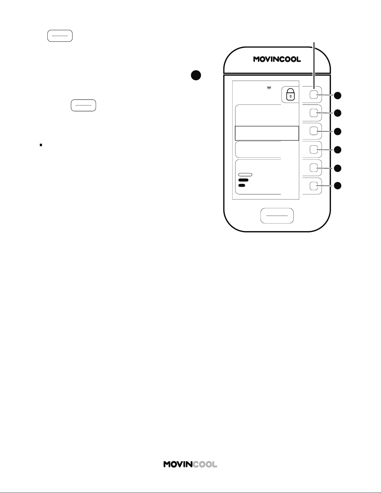
50
If
START
STOP
is pressed for an emergency stop or
pressed accidentally during SCHEDULE MODE operation,
"TEMPORARY STOP: REFER TO OPERATION MANUAL TO
RESUME OPERATION" is displayed.
1. To release TEMPORARY STOP, press and hold
A
A
for
5 seconds. A er 5 seconds, the screen below will be
shown for 3 seconds. To continue SCHEDULE MODE
operation, you must press
B
B
on the screen below in
those 3 seconds. If you do not press
B
B
in those 3
seconds, you must start SCHEDULE MODE operation
on the SCHEDULES screen.
Note:
The TEMPORARY STOP message will automatically
disappear if the next SCHEDULE MODE operation
starts.
TEMPORARY STOP DURING SCHEDULE MODE
START
STOP
A
A
B
B
C
C
D
D
E
E
F
F
CLIMATE PRO
Multi-function buons
SCHEDULES
SCHEDULE:
OFF
ON
MON
12:00 PM
START
STOP
A
A
B
B
C
C
D
D
E
E
F
F
CLIMATE PRO
Multi-function buons
COOL
75
MODE
SET TEMP
MENU
MON 12:00 PM
F
86
ROOM
TEMP
AUTO
FAN SPEED
START
STOP
A
A
B
B
C
C
D
D
E
E
F
F
CLIMATE PRO
Multi-function buons
MON
12:00 PM
MODE
COOL
FAN
SCHEDULE
HEAT
AUTO
A
51
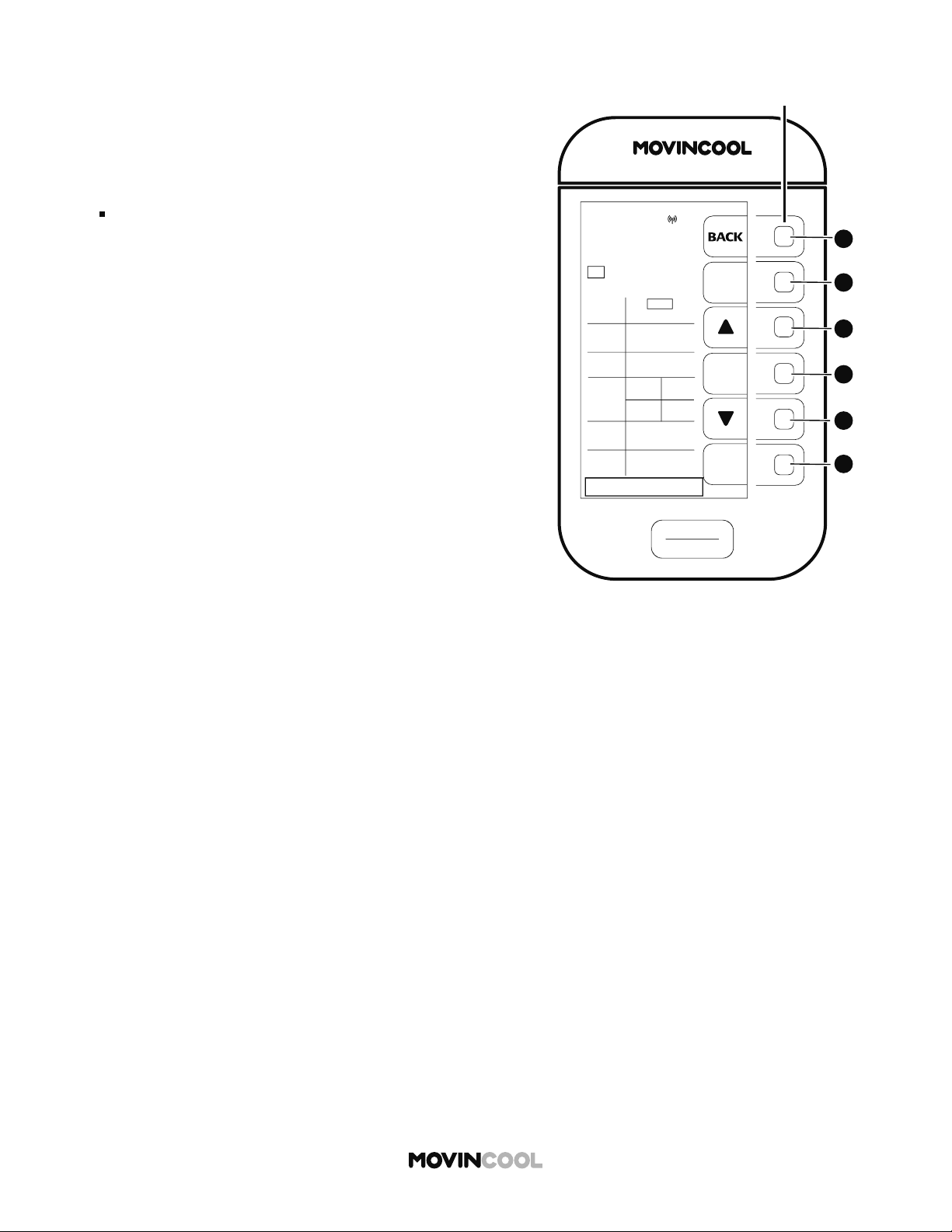
SETTING / EDITING / VIEWING SCHEDULE
1. Press
D
D
on the HOME screen.
2. Press
D
D
to select SCHEDULE on the MODE screen.
START
STOP
A
A
B
B
C
C
D
D
E
E
F
F
CLIMATE PRO
Multi-function buons
SCHEDULES
SCHEDULE:
OFF
ON
EDIT/VIEW
SCHEDULE
CLEAR
SCHEDULE
ALL KEY BUTTONS
WILL BE LOCKED
WHEN SCHEDULE
TURNS ON
MON
12:00 PM
START
STOP
A
A
B
B
C
C
D
D
E
E
F
F
CLIMATE PRO
Multi-function buons
EDIT/VIEW
SCHEDULES
NEXT
ENTER
P1 P2 P3 P4 P5
P6 P7 P8 P9 P10
MON
12:00 PM
START
TIME
12:00AM
STOP
TIME
SET
TEMP
FAN
MODE
AUTO
FAN
SPEED
HI
MODE
COOL
SUN
12:00AM
HEAT
75F
67F
AUTO
SUN
52
SETTING / EDITING / VIEWING SCHEDULE
3. To edit or view SCHEDULE MODE operation, press
E
E
on the SCHEDULES screen. The EDIT/VIEW SCHEDULES
screen is then shown.
4. Edit or view program number by pressing
F
F
Up to 10 programs can be set (P1 to P10).
5. Edit desired START TIME (day, hour, minute), STOP TIME
(day, hour, minute), MODE, SET TEMP, FAN MODE, and
FAN SPEED by pressing
C
C
or
E
E
Press
D
D
each time se ing value is determined.
6. When editing is complete, press
F
F
to save the
programs. Press
A
A
to return to the SCHEDULES
screen, and then start SCHEDULE MODE operation.
Refer to page 45.
If you wish to return to the HOME screen, press
A
A
repeatedly until the HOME screen is displayed.
START
STOP
A
A
B
B
C
C
D
D
E
E
F
F
CLIMATE PRO
Multi-function buons
EDIT/VIEW
SCHEDULES
NEXT
ENTER
P1 P2 P3 P4 P5
P6 P7 P8 P9 P10
MON
12:00 PM
START
TIME
12:00AM
STOP
TIME
SET
TEMP
FAN
MODE
AUTO
FAN
SPEED
HI
MODE
COOL
SUN
12:00AM
HEAT
75F
67F
AUTO
SUN
SETTING TIME ERROR
53
SETTING / EDITING / VIEWING SCHEDULE
Note:
If the start or stop time chosen for programs overlaps
with any other program, "SETTING TIME ERROR" will
be displayed. Press any bu on to clear the message.
Reset program times.

START
STOP
A
A
B
B
C
C
D
D
E
E
F
F
CLIMATE PRO
Multi-function buons
COOL
75
MODE
SET TEMP
MENU
MON 12:00 PM
F
86
ROOM
TEMP
AUTO
FAN SPEED
START
STOP
A
A
B
B
C
C
D
D
E
E
F
F
CLIMATE PRO
Multi-function buons
MON
12:00 PM
MODE
COOL
FAN
SCHEDULE
HEAT
AUTO
A
54
CLEARING SCHEDULE
1. Press
D
D
on the HOME screen.
2. Press
D
D
to select SCHEDULE on the MODE screen.
START
STOP
A
A
B
B
C
C
D
D
E
E
F
F
CLIMATE PRO
Multi-function buons
SCHEDULES
SCHEDULE:
OFF
ON
EDIT/VIEW
SCHEDULE
CLEAR
SCHEDULE
ALL KEY BUTTONS
WILL BE LOCKED
WHEN SCHEDULE
TURNS ON
MON
12:00 PM
55
CLEARING SCHEDULE
3. To clear SCHEDULE MODE operation, press
F
F
on the
SCHEDULES screen. The confi rmation screen is then
shown.
START
STOP
A
A
B
B
C
C
D
D
E
E
F
F
CLIMATE PRO
Multi-function buons
SCHEDULES
CLEAR ALL
ALL SET SCHEDULES
WILL BE CLEARED
FROM MEMORY
MON
12:00 PM
4. The message "ALL SET SCHEDULES WILL BE CLEARED
FROM MEMORY" is displayed. Press
B
B
if you wish to
clear all set schedules.
The screen then returns to the previous screen.
If you wish to return to the HOME screen, press
A
A
repeatedly until the HOME screen is displayed.

START
STOP
A
A
B
B
C
C
D
D
E
E
F
F
CLIMATE PRO
Multi-function buons
COOL
75
MODE
SET TEMP
MENU
MON 12:00 PM
F
86
ROOM
TEMP
AUTO
FAN SPEED
MENU
SETTING
SERVICES
KEY LOCK
MON
12:00 PM
START
STOP
A
A
B
B
C
C
D
D
E
E
F
F
CLIMATE PRO
Multi-function buons
56
ADJUSTING BRIGHTNESS
1. Press
A
A
on the HOME screen.
2. Press
B
B
to select SETTING on the MENU screen.
SETTING
DAY & TIME
DISPLAY
FAN MODE
TEMP SCALE
F
MON
12:00 PM
START
STOP
A
A
B
B
C
C
D
D
E
E
F
F
CLIMATE PRO
Multi-function buons
START
STOP
A
A
B
B
C
C
D
D
E
E
F
F
CLIMATE PRO
Multi-function buons
DISPLAY
LCD
BRIGHTNESS
+
-
ENTER
MON
12:00 PM
57
3. Press
C
C
to select DISPLAY on the SETTING screen.
ADJUSTING BRIGHTNESS
4. Press
C
C
or
E
E
to adjust the brightness level and
then press
D
D
to save.
The screen returns to the previous screen.
If you wish to return to the HOME screen, press
A
A
repeatedly until the HOME screen is displayed.

START
STOP
A
A
B
B
C
C
D
D
E
E
F
F
CLIMATE PRO
Multi-function buons
COOL
75
MODE
SET TEMP
MENU
MON 12:00 PM
F
86
ROOM
TEMP
AUTO
FAN SPEED
MENU
SETTING
SERVICES
KEY LOCK
MON
12:00 PM
START
STOP
A
A
B
B
C
C
D
D
E
E
F
F
CLIMATE PRO
Multi-function buons
58
FAN MODE
The fan mode determines whether the fan continues to
run or stop when the room temperature reaches the set
temperature. The default se ings are ON in COOL mode
and AUTO in HEAT mode.
ON : Fan constantly runs whether the unit is operating
or not.
AUTO: Fan only runs when the unit is operating.
1. Press
A
A
on the HOME screen.
2. Press
B
B
to select SETTING on the MENU screen.
SETTING
DAY & TIME
DISPLAY
FAN MODE
TEMP SCALE
F
MON
12:00 PM
START
STOP
A
A
B
B
C
C
D
D
E
E
F
F
CLIMATE PRO
Multi-function buons
START
STOP
A
A
B
B
C
C
D
D
E
E
F
F
CLIMATE PRO
Multi-function buons
FAN MODE
COOL:
ON
AUTO
MON
12:00 PM
HEAT:
AUTO
ON
59
3. Press
D
D
to select FAN MODE on the SETTING screen.
FAN MODE
4. Press
B
B
to switch to AUTO in COOL mode.
The default se ing of the FAN MODE is ON.
Press
C
C
to switch to ON in HEAT mode.
The default se ing of the FAN MODE is AUTO.
If you wish to return to the HOME screen, press
A
A
repeatedly until the HOME screen is displayed.
START
STOP
A
A
B
B
C
C
D
D
E
E
F
F
CLIMATE PRO
Multi-function buons
COOL
75
MODE
SET TEMP
MENU
MON 12:00 PM
F
86
ROOM
TEMP
AUTO
FAN SPEED
MENU
SETTING
SERVICES
KEY LOCK
MON
12:00 PM
START
STOP
A
A
B
B
C
C
D
D
E
E
F
F
CLIMATE PRO
Multi-function buons
60
CHANGING TEMPERATURE SCALE
1. Press
A
A
on the HOME screen.
TEMP SCALE
is only displayed while the unit is not in
operation.
2. Press
B
B
to select SETTING on the MENU screen.
SETTING
DAY & TIME
DISPLAY
FAN MODE
TEMP SCALE
F
MON
12:00 PM
START
STOP
A
A
B
B
C
C
D
D
E
E
F
F
CLIMATE PRO
Multi-function buons
START
STOP
A
A
B
B
C
C
D
D
E
E
F
F
CLIMATE PRO
Multi-function buons
TEMP SCALE
SETTING:
C
MON
12:00 PM
F
61
3. Press
E
E
to select TEMP SCALE on the SETTING
screen.
Note:
TEMP SCALE is only displayed while the unit is not in
operation.
CHANGING TEMPERATURE SCALE
4. Press
B
B
to switch to
C
The default se ing of the TEMP SCALE is
F
If you wish to return to the HOME screen, press
A
A
repeatedly until the HOME screen is displayed.

START
STOP
A
A
B
B
C
C
D
D
E
E
F
F
CLIMATE PRO
Multi-function buons
COOL
75
MODE
SET TEMP
MENU
MON 12:00 PM
F
86
ROOM
TEMP
AUTO
FAN SPEED
MENU
SETTING
SERVICES
KEY LOCK
MON
12:00 PM
START
STOP
A
A
B
B
C
C
D
D
E
E
F
F
CLIMATE PRO
Multi-function buons
62
KEY LOCK
Key lock disables all bu ons on the control panel.
1. Press
A
A
on the HOME screen.
2. Press
D
D
to select KEY LOCK on the MENU screen.
The HOME screen will be shown.
Note:
During SCHEDULE MODE operation, all bu ons are
automatically locked.
START
STOP
A
A
B
B
C
C
D
D
E
E
F
F
CLIMATE PRO
Multi-function buons
COOL
75
MODE
SET TEMP
MON
12:00 PM
86
ROOM
TEMP
AUTO
FAN SPEED
START
STOP
A
A
B
B
C
C
D
D
E
E
F
F
CLIMATE PRO
Multi-function buons
KEY LOCK
MON
12:00 PM
KEY LOCK
63
1. To unlock the keys, press and hold
A
A
for 5 seconds.
A er 5 seconds, the screen below will be shown for 3
seconds. If you wish to continue KEY LOCK, press
B
B
on the screen below in those 3 seconds. If you do not
press
B
B
in those 3 seconds, the HOME screen will be
displayed.
Note:
All bu ons are automatically unlocked when a self-
diagnostic code is displayed. (See page 69)
KEY UNLOCK
START
STOP
A
A
B
B
C
C
D
D
E
E
F
F
CLIMATE PRO
Multi-function buons
COOL
MODE
“TEMPORARY STOP”
REFER TO OPERATION MANUAL
TO RESUME OPERATION
75
SET TEMP
MON
12:00 PM
86
ROOM
TEMP
AUTO
FAN SPEED
64
If
START
STOP
is pressed for emergency stop or accidentally
during key lock, "TEMPORARY STOP: REFER TO OPERATION
MANUAL TO RESUME OPERATION" is displayed.
1. To release TEMPORARY STOP, press and hold
A
A
for
5 seconds.
2. Press
START
STOP
to start operation.
Note:
If you wish to lock keys, refer to page 62.
TEMPORARY STOP DURING KEY LOCK

START
STOP
A
A
B
B
C
C
D
D
E
E
F
F
CLIMATE PRO
Multi-function buons
COOL
75
MODE
SET TEMP
MENU
MON 12:00 PM
F
86
ROOM
TEMP
AUTO
FAN SPEED
MENU
SETTING
SERVICES
KEY LOCK
MON
12:00 PM
START
STOP
A
A
B
B
C
C
D
D
E
E
F
F
CLIMATE PRO
Multi-function buons
65
SERVICE INFORMATION
Machine information can be displayed.
1. Press
A
A
on the HOME screen.
2. Press
C
C
to select SERVICES on the MENU screen.
SERVICES
MACHINE
INFORMATION
MON
12:00 PM
START
STOP
A
A
B
B
C
C
D
D
E
E
F
F
CLIMATE PRO
Multi-function buons
START
STOP
A
A
B
B
C
C
D
D
E
E
F
F
CLIMATE PRO
Multi-function buons
MACHINE
INFORMATION
MACHINE
STATUS
MACHINE
RECORDS
SCAN THIS QR CODE OR
QR CODE ON THE MOVINCOOL
UNIT TO ACCESS WEBSITE AND
DOWNLOAD SERVICE MANUAL
MON
12:00 PM
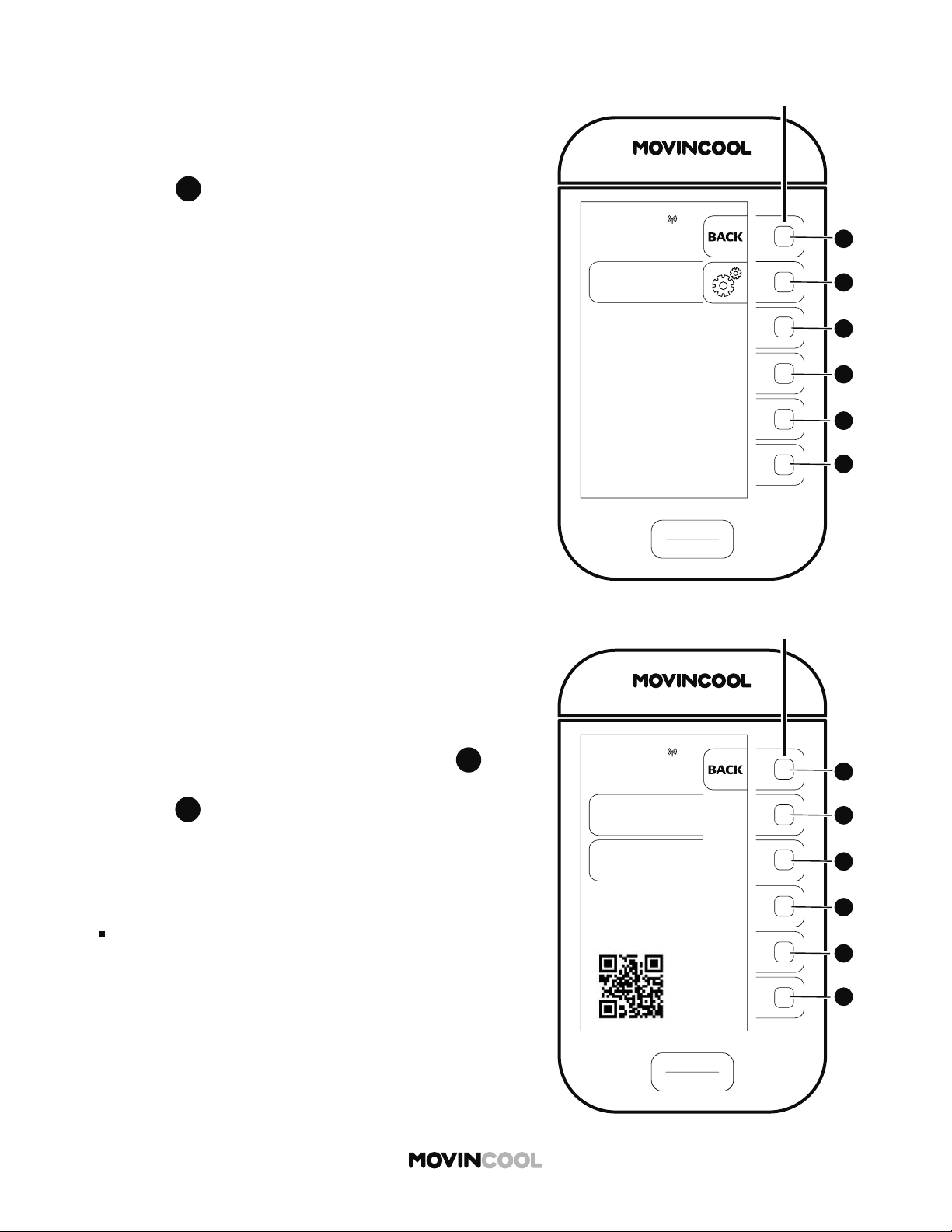
66
SERVICE INFORMATION
1. Press
B
B
to select MACHINE INFORMATION on the
SERVICES screen.
2. The MACHINE INFORMATION screen is displayed.
If you wish to see MACHINE STATUS, press
B
B
If you wish to see MACHINE RECORDS,
press
C
C
Note:
Technical information is available by scanning QR code.
START
STOP
A
A
B
B
C
C
D
D
E
E
F
F
CLIMATE PRO
Multi-function buons
MACHINE
STATUS
ODS
RTS 86 F
EXV
CTS1 89 F
CTS2
CTS3
480
15 F
50 F
14 F
MON
12:00 PM
67
SERVICE INFORMATION
3. A er pressing
B
B
on the MACHINE INFORMATION
screen, MACHINE STATUS screen is displayed.
If you wish to return to the HOME screen, press
A
A
repeatedly until the HOME screen is displayed.
4. A er pressing
C
C
on the MACHINE INFORMATION
screen, MACHINE RECORDS screen is displayed.
If you wish to return to the HOME screen, press
A
A
repeatedly until the HOME screen is displayed.
START
STOP
A
A
B
B
C
C
D
D
E
E
F
F
CLIMATE PRO
Multi-function buons
MACHINE
RECORDS
HEAT TIME
COOL TIME
200 HR
TOTAL TIME
5000 HR
DEF TIME
DIAG CODE 1
AL1
DIAG CODE 2
DIAG CODE 3
ID FAN TIME
OD FAN TIME
1000 HR
560 HR
100 HR
AS
AL2
500 HR
MON
12:00 PM
START
STOP
A
A
B
B
C
C
D
D
E
E
F
F
CLIMATE PRO
Multi-function buons
DIAGNOSTIC
CODE: HP
1. CLEAN AIR FILTERS
2. ENSURE 24 INCHES
CLEARANCE IN FRONT
OF AIR INLETS
3. CHECK OPERATING
TEMPERATURE AND
HUMIDITY CONDITION
4. ENSURE AIR FLOW
IS NOT BLOCKED OR
RESTRICTED
5. PRESS CLEAR
BUTTON TO RESET
ERROR TIME
MON 8:00 AM
HIGH PRESSURE
PROTECTION IS ACTIVATED
CLEAR
MON
12:00 PM
68
SELF-DIAGNOSTIC CODES
1. If a self-diagnostic code is displayed, follow the
on-screen instructions.
2. If CLEAR is shown, press
F
F
to reset.
The HOME screen will be shown.
Refer to "List of Self-diagnostic codes" on the next page.
Note:
If a self-diagnostic code is displayed again a er
following the instructions, contact dealer or qualifi ed
technician.
69
LIST OF SELF-DIAGNOSTIC CODES
CODE CONDITION SOLUTION
AL1 Alarm device 1 is activated
1. Check FA-1, FA-2 connection
2. Identify and correct condition causing alarm
3. Press CLEAR bu on to reset
AL2 Alarm device 2 is activated
1. Check AL-1, AL-2 connection
2. Identify and correct condition causing alarm
3. Press CLEAR bu on to reset
FL Drain tank is full
1. Empty tank
2. Place tank back in unit
3. Press CLEAR bu on to reset
HP
High pressure protection
is activated
1. Clean air fi lters
2. Ensure 24 inches clearance in front of air inlets
3.
Check operating temperature and humidity
condition
4. Ensure air flow is not blocked or restricted
5. Press CLEAR bu on to reset
PU Condensate pump error
1. Check drain line for kink, blockage and improper
routing
2. Identify and correct condition
3. Press CLEAR bu on to reset
CF Cooling Failure Contact dealer or qualifi ed technician
E1 RTS thermistor failure Contact dealer or qualifi ed technician
E2 ODS thermistor failure Contact dealer or qualifi ed technician
E3 CTS1 thermistor failure Contact dealer or qualifi ed technician
E4 CTS2 thermistor failure Contact dealer or qualifi ed technician
E5 CTS3 thermistor failure Contact dealer or qualifi ed technician
70
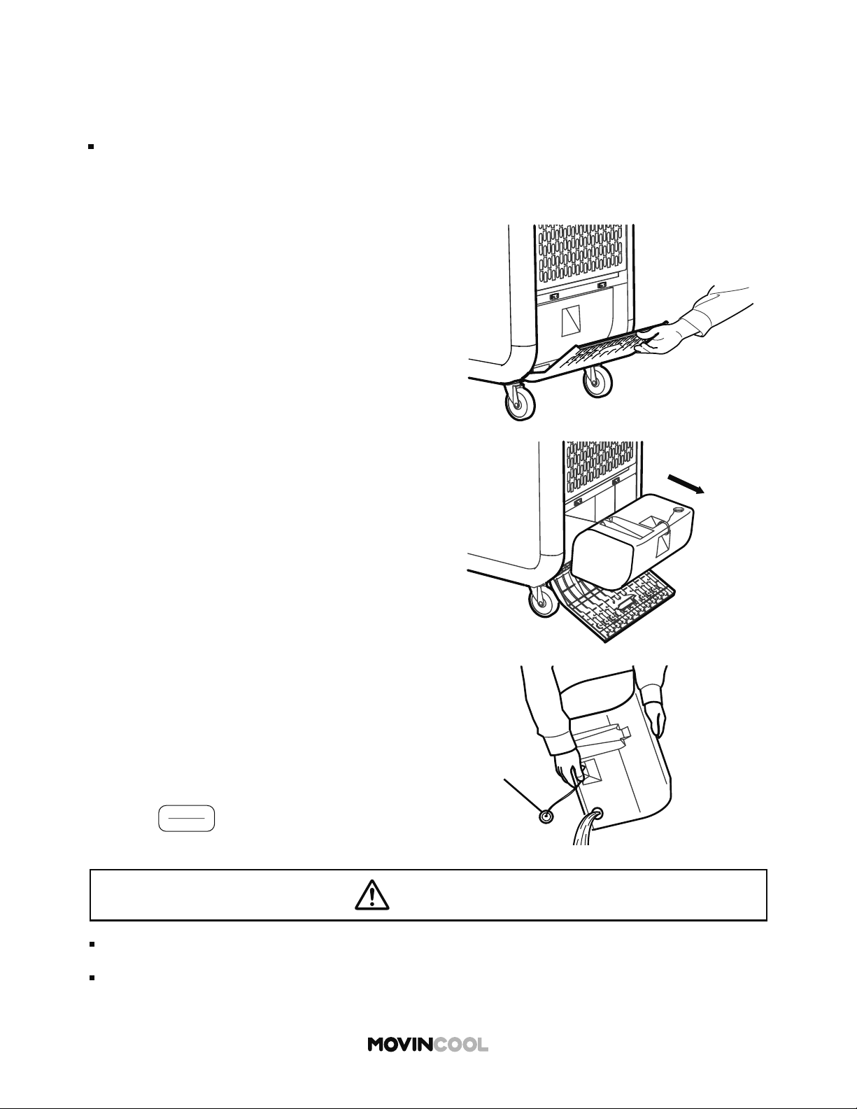
EMPTYING THE DRAIN TANK
During COOL mode, water accumulates in the drain tank. When the tank becomes full, the
self-diagnostic code “FL” is displayed and the unit turns off automatically.
Note:
If it is necessary to empty the drain tank before it is full. the unit must be turned o before
emptying. If SCHEDULE MODE operation is running, stop the operation fi rst. (See page 47)
Cap
1. Open the drain tank cover.
2. Remove the tank.
3. Remove the cap and empty the tank.
4. Replace the cap and return the tank to the unit.
5. Close the tank cover.
6. Press CLEAR bu on to reset the self-diagnostic
code.
7. Press
START
STOP
to restart the operation.
CAUTION
When the tank is full, remove water immediately.
Do not operate without the tank. Ensure that the tank is correctly installed.
Water leaks from the unit may cause property damage or injury due to wet floor.
71
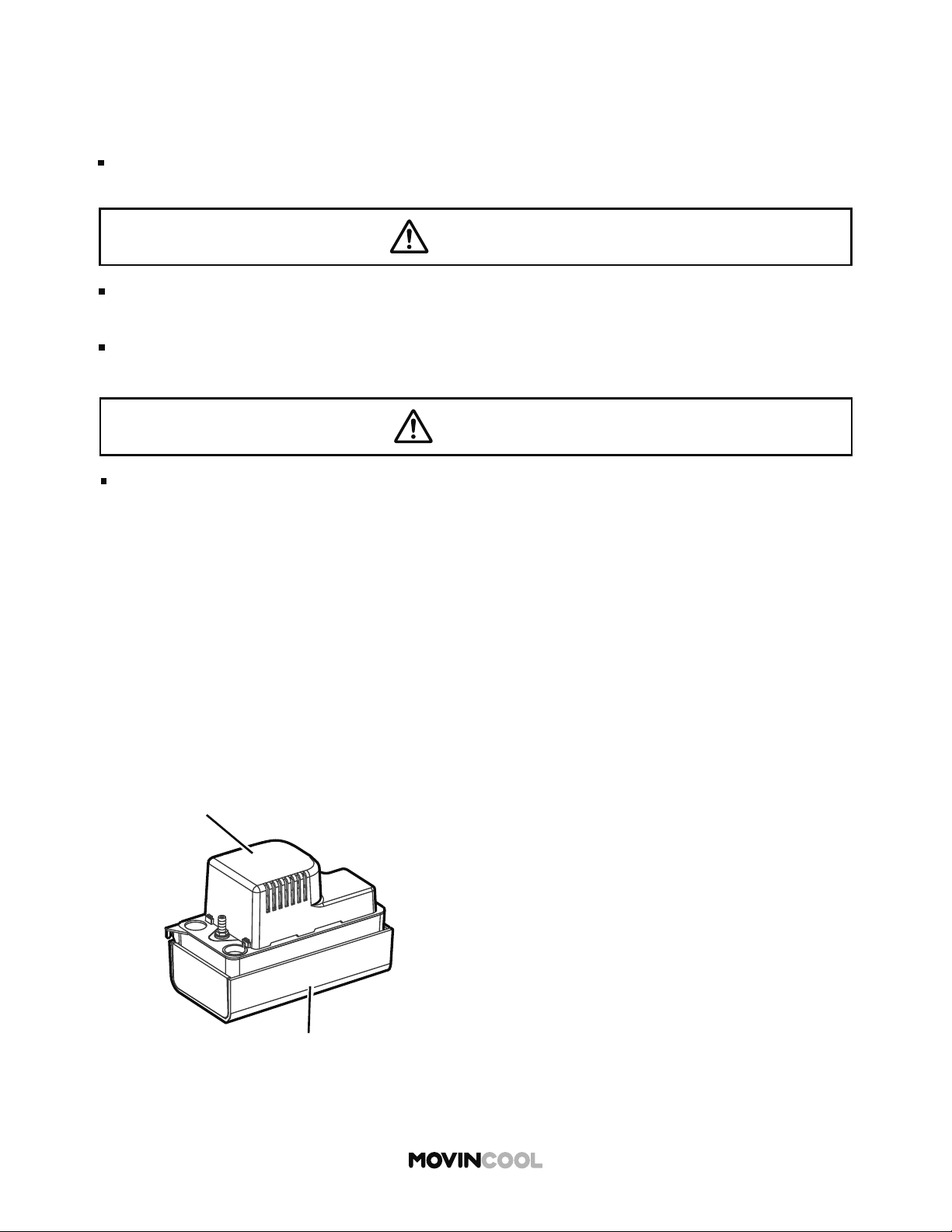
CONDENSATE PUMP KIT (OPTIONAL ACCESSORY)
Condensate pump kit is available to allow continuous unit operation and eliminate the need for
emptying the drain tank.
Note:
The compressor does not operate while the condensate pump is discharging the water
from the reservoir.
If a failure occurs, the unit automatically stops and the LCD displays PU.
Follow the on-screen instructions.
For optimal performance of condensate pump, follow these instructions:
1. Remove any dirt or debris from the bo om of the reservoir tank.
2. On a monthly basis, check the condensate drain hose for kinks, blockage or any other damage
that may prevent the unit from draining properly.
3. Always replace the fan motor cover to keep electrical parts free of dust, dirt and any other
foreign material.
Condensate Pump Reservoir
Motor Cover
WARNING
CAUTION
For installation of the condensate pump, consult your MovinCool dealer or qualified
technician. Incorrect installation may cause fire, electric shock or water leaks.
When performing maintenance or troubleshooting, stop the operation and turn off the
breaker to avoid causing possible electric shock or injury.
Ensure smooth drainage through the hose. If the hose is clogged, it may cause malfunction
and property damage due to water leaks.

72
MAINTENANCE
CLEANING AIR FILTERS
Clean air filters once a week. If the unit is used in a dusty environment, more frequent cleaning is
required. Dirty air filters will result in poor performance.
Wire Frame
Panel
Filter
1. Turn the unit o by pressing
START
STOP
If SCHEDULE MODE operation is running, stop
the operation. (See page 47)
2. Remove front and side panel.
3. Unfasten upper wire frame by moving the two
points shown outwards, and then remove fi lters.
4. Clean o the dust with a vacuum cleaner or rinse
in cold or lukewarm water.
5. If necessary, wash with a neutral detergent and
rinse with running water.
6. Allow fi lters to dry in shade, and then reinstall.
WARNING
When performing maintenance or troubleshooting, stop the operation and remove the power plug.
If you touch high-voltage or rotating parts, it may cause electric shock or injury.
73
CLEANING THE UNIT
BEFORE LONG TERM STORAGE
1. Operate the unit in FAN ONLY mode for 8 hours to dry out the inside completely.
2. Turn the unit o and unplug the power cord.
3. Check the power cord. If dirty, wipe o with a clean dry cloth. If damage or excess play is
found on the plug prongs, then contact your MovinCool dealer for power cord replacement.
4. Check the air fi lters and clean if dirty. Replace if damaged.
5. Check the drain tank and empty the water. Replace if damaged.
6. Check the exterior of the unit. If dirty, clean with a damp cloth or mild nonabrasive cleaner.
If any part requires repair or replacement, contact your MovinCool dealer or qualifi ed technician.
7. Store in a clean and dry environment.
Check plug, power cord, drain tank and hose regularly for damage.
CAUTION
WARNING
Wipe the external surface with either a dry cloth or a cloth dampened in a mild cleaner.
Using an organic solvent such as benzene or thinner, may crack or scratch the unit which may
result in electric shock or injury.
Do not wash the unit with water. This may cause fi re, electric shock or malfunction.
Remove dust from the power plug regularly. Incorrect maintenance may cause fi re.
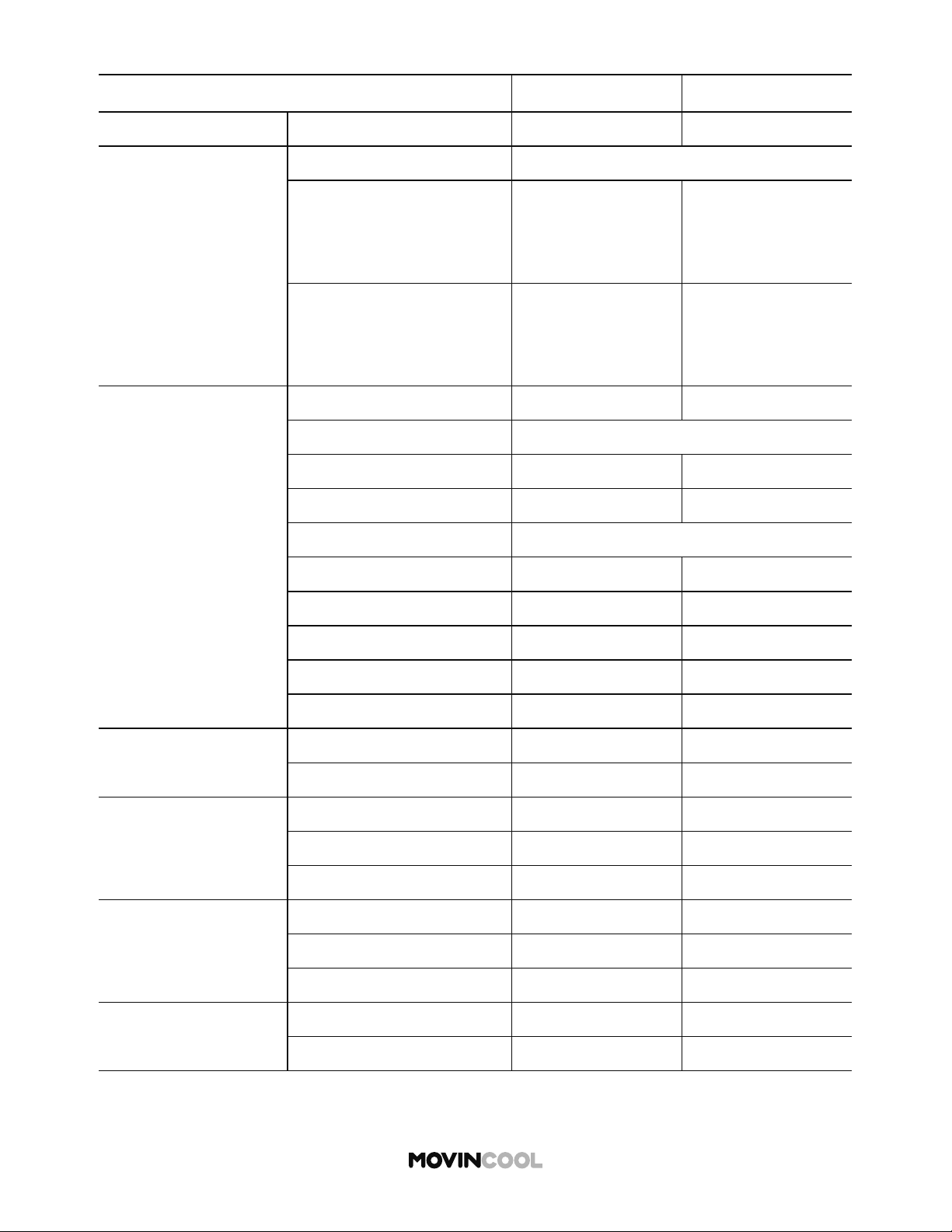
MODEL NAME CLIMATE PRO D12 CLIMATE PRO D18
Electronic Features Control Programmable Programmable
Cooling Capacity
Rating Conditions:
Cooling:
80°F DB, 67°F WB
(Indoor and outdoor)
11,450 Btu/h 15,500 Btu/h
Heating:
70°F DB, 60°F WB (indoor)
47°F DB, 43°F WB (outdoor)
9,900 Btu/h 13,100 Btu/h
Electrical
Characteristics
Voltage Requirement 115V, 1Phase, 60Hz 115V, 1Phase, 60Hz
Total Power Consumption:
Cooling 1.38 kW 1.56 kW
Heating 1.25 kW 1.31 kW
Current Consumption:
Cooling 12.4 amps 13.8 amps
Heating 11.3 amps 11.7 amps
Recommended Fuse Size 15 amps 20 amps
NEMA Plug Confi guration 5-15 5-20
Min. - Max. Voltage 104 -127 104 -127
Fans: Motor Output
Indoor 0.06 kW 0.06 kW
Outdoor 0.12 kW 0.12 kW
Indoor Heat Exchanger
Fan Type Centrifugal Centrifugal
Max. Air Flow (hi/mid/low) 420/340/280 CFM 540/440/350 CFM
Max. External Static Pressure
0.31 IWG 0.31 IWG
Outdoor Heat
Exchanger
Fan Type Centrifugal Centrifugal
Max. Air Flow 760 CFM 825 CFM
Max. External Static Pressure
0.19 IWG 0.19 IWG
Compressor
Type Hermetic Rotary Hermetic Rotary
Output 0.75 kW 0.90 kW
74
TECHNICAL SPECIFICATIONS
Specifi cations are subject to change without notice.
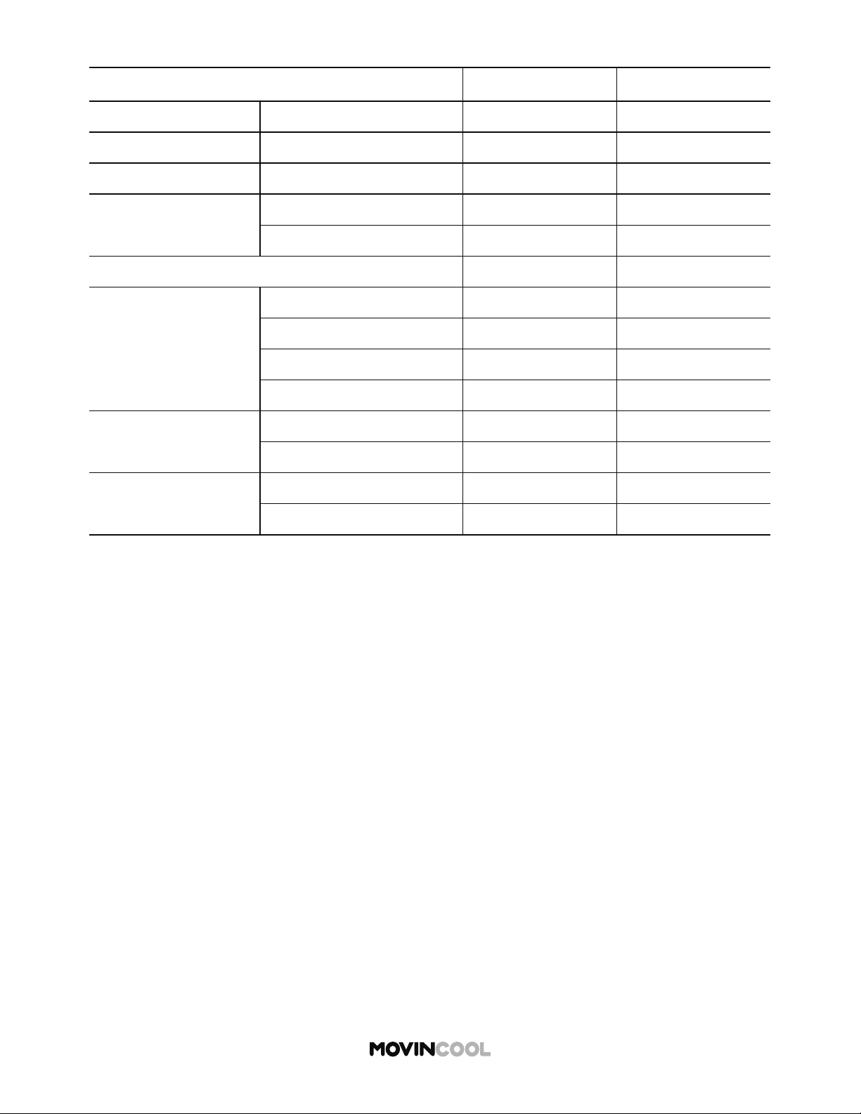
MODEL NAME CLIMATE PRO D12 CLIMATE PRO D18
Refrigerant Type R-410A R-410A
Dimensions W x D x H 22 x 27 x 47 in 22 x 27 x 51 in
Weight Net / Shipping 181/218 lb 198/236 lb
Power Cord
Gauge 14 AWG (3-core) 12 AWG (3-core)
Length 10 10
Condensate Tank Capacity 5 gal 5 gal
Operating Conditions:
Min. - Max.
(@ 50% RH)
Cooling 65°F - 95°F 65°F - 95°F
Heating: without Plenum 40°F - 80°F 40°F - 80°F
With Plenum (Indoor) 40°F - 80°F 40°F - 80°F
With Plenum (outdoor) 24°F - 80°F 24°F - 80°F
Max. Duct Length
Per Cold Duct Hose 30 25
Hot Duct Hose 100 100
Max. Sound Level
With Duct (hi/mid/low) 61/60/59 dB(A) 65/64/63 dB(A)
Without Duct (hi/mid/low) 62/61/60 dB(A) 66/65/64 dB(A)
75
TECHNICAL SPECIFICATIONS
Specifi cations are subject to change without notice.
76
TROUBLESHOOTING
Review the following before calling your MovinCool dealer or qualifi ed technician.
PROBLEM POSSIBLE CAUSE SOLUTION
Unit does
not operate
No display on
LCD screen
Unit is not connected to power
supply
Check connection to mains
supply. Try plugging it in
Main power is o Check circuit breaker is on
Ground fault protective
breaker is tripped
Reset ground fault protective
breaker
LCDI power cord is tripped Reset power cord
LCDI power cord is damaged Replace power cord
LCD displays
notifi cation
OUTSIDE OPERATING RANGE
Check operating conditions on
HEAT mode
DEFROST
Operation resumes a er
defrosting is completed
LCD displays
normally, but
unit does not
start
Ambient temperature has
reached set temperature and
unit has stopped
Adjust set temperature
Poor cooling or heating
performance
Air inlets or outlets are
blocked
Keep a minimum clearance of
24 inches (610 mm) from walls or
other objects
Air fi lters are dirty Clean air fi lters
Temperature se ing is too
high or low
Adjust temperature se ing
Water leaking from unit
Tank is not correctly installed Position tank
Tank inlet is clogged Unclog tank inlet
Drain hose has a kink or is
blocked
Check and clean drain hose

77
WARRANTY STATEMENT
DENSO PRODUCTS AND SERVICES AMERICAS, INC. ("DENSO") warrants its MOVINCOOL products
only to the extent stated in its o cial wri en warranties. Unless otherwise specifi cally provided in
writing by DENSO, DENSO warrants to the original end-user that the products shall be free of defects
in materials or workmanship and will function in accordance with DENSO's published specifi cations
under ordinary intended use and service for a period listed below beginning from the date of purchase
on the invoice to the end-user:
Model(s): Climate Pro D12, Climate Pro D18
Warranty: 3 Years with warranty registration OR 1 Year for unregistered unit
DENSO shall, at its sole discretion, repair or replace any defective product covered by this warranty.
Such remedy shall be end-user's sole remedy with respect to any particular defect in the products.
This warranty does not cover defects or malfunctions which result from causes beyond DENSO's
control, including, without limitation, (i) unusual physical or electrical stress; (ii) accident, neglect,
abuse, misuse or other abnormal use; (iii) failure to perform routine maintenance in accordance with
DENSO's recommended procedures; (iv) normal wear and tear; (v) repairs or a empted repairs by an
unauthorized person; (vi) modifi cations or alterations to the products; (vii) use with parts or devices
not supplied or approved by DENSO; (viii) improper installation or service; (ix) shipping damage to any
units or spare parts during shipping. This includes and is not limited to compressors and heat
exchangers. This warranty shall extend only to the original end-user and shall be void if any labels or
other identifying marks permanently a xed to products when shipped by DENSO are removed,
altered, defaced or obliterated.
TO THE EXTENT PERMITTED BY LAW, THIS WARRANTY, AS LIMITED HEREIN, SHALL BE IN LIEU
OF AND EXCLUSIVE OF ALL OTHER WARRANTIES, EITHER EXPRESSED OR IMPLIED, ON THE PART
OF DENSO PRODUCTS AND SERVICES AMERICAS, INC., OR DENSO CORPORATION, WHETHER
ARISING FROM LAW, COURSE OF DEALING, USAGE OF TRADE, OR OTHERWISE, INCLUDING
WITHOUT LIMITATION ANY IMPLIED WARRANTY OF MERCHANTABILITY OR FITNESS OF A
PARTICULAR PURPOSE OR ANY LIABILITY FOR COMMERCIAL LOSSES BASED UPON NEGLIGENCE
OR MANUFACTURER'S STRICT LIABILITY. EXCEPT AS EXPRESSLY PROVIDED HEREIN, NEITHER
DENSO PRODUCTS AND SERVICES AMERICAS, INC., NOR DENSO CORPORATION WILL, IN ANY
EVENT, BE LIABLE FOR LOST PROFITS, COSTS OF PROCESSING, INJURY, GOODWILL, OR ANY OTHER
CONSEQUENTIAL DAMAGES OF ANY KIND ARISING FROM BREACH OF THIS WARRANTY.
DENSO PRODUCTS AND SERVICES AMERICAS, INC. reserves the right to make changes without prior
notice.
R

78
DATA PRIVACY DISCLOSURE
Tracking of Machine Operation Data
This Unit is equipped with an embedded module that collects and transmits to us data on the
Unit’s operational performance (“Machine Operation Data”), including:
1. Hours of operation
2. Control Panel se ings
3. Ambient Temperature
4. Error Codes
5. Geolocation
How We Use the Data We Collect
The embedded module collects the Machine Operation Data in a format that is used for business
analysis purposes, and does not identify the user. However, Machine Operation Data may become
personal information about an identifi able individual when it is read together or combined with other
personal information.
We use the Machine Data to:
(i) Monitor the performance of the Unit.
(ii) Analyze the performance of the Unit under actual environmental conditions.
(iii) Analyze the performance of the Unit under actual user demand conditions.
(iv) Locate the Unit.
(v) Use aggregate data to enhance the performance, e ciency and usefulness of our products.
(vi) Use aggregate data to modify, improve or develop new products, services and technologies.
(vii) Comply with legal, regulatory or contractual requirements.
When you purchase or lease a Unit from us or one of our authorized distributors or resellers, we may
obtain personally identifying information about you such as your name, address, phone number and
e-mail address (“Personally Identifying Information”). We and our authorized distributors or resellers
may use Machine Operation Data together with Personally Identifying Information to:
(i) Assist in trouble shooting and repair.
(ii) Provide any safety updates or recall notices.
(iii) Provide warranty service.
(iv) Provide and improve customer support.
(v) Locate the Unit.
The Machine Operation Data will be transmi ed to us in the United States. While Machine Operation
Data is in the United States it may be accessed by the courts, law enforcement and national security
authorities pursuant to local U.S. laws.
Sharing of Data
We shall use Machine Operation Data primarily for our own business purposes. We may also share
your Unit’s Machine Operation Data with the distributor, reseller or owner that sells or leases the Unit
to you. This means that they will be able to determine the geolocation of the Unit.
We may disclose Machine Operation Data to a third party service provider in the United States for
processing in order to analyze the performance of the Units and make improvements. The third party
service provider is contractually bound to use Machine Operation Data solely for the purpose of
providing services to us and not for their own purposes.

79
DATA PRIVACY DISCLOSURE
How Long We Keep Your Information
We may keep the information we collect for as long as necessary to provide products or services to
you, to operate our business, to enable us to communicate with you, for our safety, research, evaluation
of use, or troubleshooting purposes, or to satisfy our legal or contractual obligations. Where required,
we will de-identify or dispose of the information we collect when we no longer need it for the uses
described above.
CONSUMER RIGHT TO “OPT OUT” OF DATA SHARING
If you are a consumer and you do not want us to provide your Unit’s Machine Operation Data,
including the Unit’s geolocation, or your Personally Identifying Information to your supplying
distributor, reseller or owner, you may “Opt Out” by contacting us at 1-800-264-9573 or
www.movincool.com
If you are a consumer and you do not want us to use a third party service provider to process
your Unit’s Machine Operation Data, you may “Opt Out” by contacting us at 1-800-264-9573
or www.movincool.com
CONSENT TO OUR COLLECTION, USE AND DISCLOSURE OF MACHINE
OPERATION DATA
By reading this notice and using this Unit, you consent to our collection, use and disclosure of
Machine Operation Data. If you do not wish to give your consent, we will disable the Machine
Operation Data tracking module upon request at 1-800-264-9573 or www.movincool.com
CONSENT TO OUR COLLECTION, USE AND DISCLOSURE OF GEOLOCATION DATA
By reading this notice and using this Unit, you consent to our collection, use and disclosure
of geolocation data. If you do not wish to give your consent, we will disable the Machine
Operation Data tracking module upon request at 1-800-264-9573 or www.movincool.com
The tracking of geolocation data is an integral function of the Machine Operation Data tracking
module. Therefore, disabling the geolocation functionality will disable all other functionality of
the Machine Operation Data tracking module. If the Machine Operation Data tracking module
is disabled, we will not be able to provide you with any accompanying customer service
enhancements.
CONSUMER RIGHT TO WITHDRAW CONSENT
If you no longer wish to consent to our use, collection and disclosure of Machine Operation
Data, you may contact us at 1-800-264-9573 or www.movincool.com and we will disable the
Machine Operation Data tracking module.
For further information about our privacy policy or our privacy management practices, please refer to
www.movincool.com

DENSO PRODUCTS AND SERVICES AMERICAS, INC.
Long Beach, CA 90810
www.movincool.com
First Edition: January 2020
P/N: 484007-4770EN