SERVICE MANUAL
OFFICE PRO 36
SERIAL NUMBER FROM APRIL 2007 (0407) TO PRESENT
DocID: 00G00010EA

© 2008 DENSO SALES CALIFORNIA, INC.
All rights reserved. This book may not be reproduced or copied, in
whole or in part, without the written permission of the publisher. DENSO
SALES CALIFORNIA, INC. reserves the right to make changes without
prior notice. MovinCool is a registered trademark of DENSO
Corporation.

Table of Contents
Table of Contents
Operation Section
1. PRECAUTIONS FOR SAFETY
1.1 Foreword. . . . . . . . . . . . . . . . . . . . . . . . . . . . . . . . . . . . . . . . . . . . . . . . . . . . . . . . . . . . . . . . . . . . . . . 6
1.2 Definition of Terms . . . . . . . . . . . . . . . . . . . . . . . . . . . . . . . . . . . . . . . . . . . . . . . . . . . . . . . . . . . . . . . 6
1.3 General Precautions. . . . . . . . . . . . . . . . . . . . . . . . . . . . . . . . . . . . . . . . . . . . . . . . . . . . . . . . . . . . . . 6
2. GENERAL DESCRIPTION
2.1 Spot Cooler. . . . . . . . . . . . . . . . . . . . . . . . . . . . . . . . . . . . . . . . . . . . . . . . . . . . . . . . . . . . . . . . . . . . . 7
2.2 Compact Design. . . . . . . . . . . . . . . . . . . . . . . . . . . . . . . . . . . . . . . . . . . . . . . . . . . . . . . . . . . . . . . . . 7
2.3 Easy Transportation and Installation. . . . . . . . . . . . . . . . . . . . . . . . . . . . . . . . . . . . . . . . . . . . . . . . . . 7
2.4 Energy Conservation . . . . . . . . . . . . . . . . . . . . . . . . . . . . . . . . . . . . . . . . . . . . . . . . . . . . . . . . . . . . . 7
3. CONSTRUCTION
3.1 Exterior Dimensions . . . . . . . . . . . . . . . . . . . . . . . . . . . . . . . . . . . . . . . . . . . . . . . . . . . . . . . . . . . . . . 8
3.2 Exterior Components . . . . . . . . . . . . . . . . . . . . . . . . . . . . . . . . . . . . . . . . . . . . . . . . . . . . . . . . . . . . . 9
3.3 Internal Structure . . . . . . . . . . . . . . . . . . . . . . . . . . . . . . . . . . . . . . . . . . . . . . . . . . . . . . . . . . . . . . . 10
3.4 Basic Construction . . . . . . . . . . . . . . . . . . . . . . . . . . . . . . . . . . . . . . . . . . . . . . . . . . . . . . . . . . . . . . 10
3.5 Air Flow. . . . . . . . . . . . . . . . . . . . . . . . . . . . . . . . . . . . . . . . . . . . . . . . . . . . . . . . . . . . . . . . . . . . . . . 11
3.6 Compressor and Fans . . . . . . . . . . . . . . . . . . . . . . . . . . . . . . . . . . . . . . . . . . . . . . . . . . . . . . . . . . . 11
3.7 Drain Tanks. . . . . . . . . . . . . . . . . . . . . . . . . . . . . . . . . . . . . . . . . . . . . . . . . . . . . . . . . . . . . . . . . . . . 11
4. SPECIFICATIONS
4.1 Technical Specifications . . . . . . . . . . . . . . . . . . . . . . . . . . . . . . . . . . . . . . . . . . . . . . . . . . . . . . . . . . 12
4.2 Characteristics (at 230 V). . . . . . . . . . . . . . . . . . . . . . . . . . . . . . . . . . . . . . . . . . . . . . . . . . . . . . . . . 14
4.3 Characteristics (at 208 V). . . . . . . . . . . . . . . . . . . . . . . . . . . . . . . . . . . . . . . . . . . . . . . . . . . . . . . . . 15
5. REFRIGERANT SYSTEM
5.1 Refrigerant System Construction . . . . . . . . . . . . . . . . . . . . . . . . . . . . . . . . . . . . . . . . . . . . . . . . . . . 16
5.2 Compressor . . . . . . . . . . . . . . . . . . . . . . . . . . . . . . . . . . . . . . . . . . . . . . . . . . . . . . . . . . . . . . . . . . . 17
5.3 Condenser . . . . . . . . . . . . . . . . . . . . . . . . . . . . . . . . . . . . . . . . . . . . . . . . . . . . . . . . . . . . . . . . . . . . 18
5.4 Capillary Tube. . . . . . . . . . . . . . . . . . . . . . . . . . . . . . . . . . . . . . . . . . . . . . . . . . . . . . . . . . . . . . . . . . 18
5.5 Evaporator . . . . . . . . . . . . . . . . . . . . . . . . . . . . . . . . . . . . . . . . . . . . . . . . . . . . . . . . . . . . . . . . . . . . 18
5.6 High Pressure Switch . . . . . . . . . . . . . . . . . . . . . . . . . . . . . . . . . . . . . . . . . . . . . . . . . . . . . . . . . . . . 18
6. ELECTRICAL SYSTEM
6.1 Circuit Diagram and Control Box . . . . . . . . . . . . . . . . . . . . . . . . . . . . . . . . . . . . . . . . . . . . . . . . . . . 19
6.2 Basic Operation of The Office Pro 36 Electrical Circuit . . . . . . . . . . . . . . . . . . . . . . . . . . . . . . . . . . 20
6.3 Control Box. . . . . . . . . . . . . . . . . . . . . . . . . . . . . . . . . . . . . . . . . . . . . . . . . . . . . . . . . . . . . . . . . . . . 21

Table of Contents
6.4 Fan Motor . . . . . . . . . . . . . . . . . . . . . . . . . . . . . . . . . . . . . . . . . . . . . . . . . . . . . . . . . . . . . . . . . . . . . 23
6.5 Compressor Motor . . . . . . . . . . . . . . . . . . . . . . . . . . . . . . . . . . . . . . . . . . . . . . . . . . . . . . . . . . . . . . 24
6.6 Power Cord with LCDI . . . . . . . . . . . . . . . . . . . . . . . . . . . . . . . . . . . . . . . . . . . . . . . . . . . . . . . . . . . 24
6.7 Drain Switch . . . . . . . . . . . . . . . . . . . . . . . . . . . . . . . . . . . . . . . . . . . . . . . . . . . . . . . . . . . . . . . . . . . 25
6.8 Condensate Pump Kit (optional). . . . . . . . . . . . . . . . . . . . . . . . . . . . . . . . . . . . . . . . . . . . . . . . . . . . 26
6.9 Automatic Restart after Power Interruption. . . . . . . . . . . . . . . . . . . . . . . . . . . . . . . . . . . . . . . . . . . . 26
6.10 Compressor Protection. . . . . . . . . . . . . . . . . . . . . . . . . . . . . . . . . . . . . . . . . . . . . . . . . . . . . . . . . . . 26
6.11 Temperature Control. . . . . . . . . . . . . . . . . . . . . . . . . . . . . . . . . . . . . . . . . . . . . . . . . . . . . . . . . . . . . 26
6.12 Fan Mode Control Switch . . . . . . . . . . . . . . . . . . . . . . . . . . . . . . . . . . . . . . . . . . . . . . . . . . . . . . . . . 27
6.13 Temperature Scale Display Switch. . . . . . . . . . . . . . . . . . . . . . . . . . . . . . . . . . . . . . . . . . . . . . . . . . 27
6.14 Warning Signal Connection (Output Signal Terminal L+ and L-) . . . . . . . . . . . . . . . . . . . . . . . . . . . 28
6.15 Fire Alarm Control Panel Connection (Input Signal Terminal E+ and E-). . . . . . . . . . . . . . . . . . . . . 28

Table of Contents
Repair Section
7. TROUBLESHOOTING
7.1 Troubleshooting . . . . . . . . . . . . . . . . . . . . . . . . . . . . . . . . . . . . . . . . . . . . . . . . . . . . . . . . . . . . . . . . 29
7.2 Self-Diagnostic Codes . . . . . . . . . . . . . . . . . . . . . . . . . . . . . . . . . . . . . . . . . . . . . . . . . . . . . . . . . . . 30
7.3 Troubleshooting Chart . . . . . . . . . . . . . . . . . . . . . . . . . . . . . . . . . . . . . . . . . . . . . . . . . . . . . . . . . . . 32
7.4 Basic Inspection . . . . . . . . . . . . . . . . . . . . . . . . . . . . . . . . . . . . . . . . . . . . . . . . . . . . . . . . . . . . . . . . 37
8. DISASSEMBLY
8.1 Parts Construction . . . . . . . . . . . . . . . . . . . . . . . . . . . . . . . . . . . . . . . . . . . . . . . . . . . . . . . . . . . . . . 39
8.2 Disassembly . . . . . . . . . . . . . . . . . . . . . . . . . . . . . . . . . . . . . . . . . . . . . . . . . . . . . . . . . . . . . . . . . . . 40
8.3 Removal of Electrical Parts. . . . . . . . . . . . . . . . . . . . . . . . . . . . . . . . . . . . . . . . . . . . . . . . . . . . . . . . 43
8.4 Removal of Blower Assembly. . . . . . . . . . . . . . . . . . . . . . . . . . . . . . . . . . . . . . . . . . . . . . . . . . . . . . 47
8.5 Inspection of Capacitor (for Fan Motor and Compressor) . . . . . . . . . . . . . . . . . . . . . . . . . . . . . . . . 49
8.6 Inspection of Drain Switch . . . . . . . . . . . . . . . . . . . . . . . . . . . . . . . . . . . . . . . . . . . . . . . . . . . . . . . . 49
8.7 Inspection of Fan Motor . . . . . . . . . . . . . . . . . . . . . . . . . . . . . . . . . . . . . . . . . . . . . . . . . . . . . . . . . . 50
8.8 Inspection of Compressor Motor. . . . . . . . . . . . . . . . . . . . . . . . . . . . . . . . . . . . . . . . . . . . . . . . . . . . 50
8.9 Inspection of Wiring Connection. . . . . . . . . . . . . . . . . . . . . . . . . . . . . . . . . . . . . . . . . . . . . . . . . . . . 51
8.10 Inspection of Thermistor. . . . . . . . . . . . . . . . . . . . . . . . . . . . . . . . . . . . . . . . . . . . . . . . . . . . . . . . . . 51
8.11 Inspection . . . . . . . . . . . . . . . . . . . . . . . . . . . . . . . . . . . . . . . . . . . . . . . . . . . . . . . . . . . . . . . . . . . . . 51
9. REFRIGERANT SYSTEM REPAIR
9.1 Repair of Refrigerant System . . . . . . . . . . . . . . . . . . . . . . . . . . . . . . . . . . . . . . . . . . . . . . . . . . . . . . 52
9.2 Removal of Refrigeration Cycle Components. . . . . . . . . . . . . . . . . . . . . . . . . . . . . . . . . . . . . . . . . . 54
9.3 Charging the System with R-410A Refrigerant. . . . . . . . . . . . . . . . . . . . . . . . . . . . . . . . . . . . . . . . . 55
9.4 Refrigerant Charging Work. . . . . . . . . . . . . . . . . . . . . . . . . . . . . . . . . . . . . . . . . . . . . . . . . . . . . . . . 60
10. REASSEMBLY
10.1 Removal of Unit . . . . . . . . . . . . . . . . . . . . . . . . . . . . . . . . . . . . . . . . . . . . . . . . . . . . . . . . . . . . . . . . 62
10.2 Compressor Mounting . . . . . . . . . . . . . . . . . . . . . . . . . . . . . . . . . . . . . . . . . . . . . . . . . . . . . . . . . . . 62
10.3 Blower Assembly . . . . . . . . . . . . . . . . . . . . . . . . . . . . . . . . . . . . . . . . . . . . . . . . . . . . . . . . . . . . . . . 62
10.4 Wiring Notice . . . . . . . . . . . . . . . . . . . . . . . . . . . . . . . . . . . . . . . . . . . . . . . . . . . . . . . . . . . . . . . . . . 63
10.5 Perform the Inspection . . . . . . . . . . . . . . . . . . . . . . . . . . . . . . . . . . . . . . . . . . . . . . . . . . . . . . . . . . . 63
10.6 Caster Maintenance . . . . . . . . . . . . . . . . . . . . . . . . . . . . . . . . . . . . . . . . . . . . . . . . . . . . . . . . . . . . . 63
10.7 Schematic. . . . . . . . . . . . . . . . . . . . . . . . . . . . . . . . . . . . . . . . . . . . . . . . . . . . . . . . . . . . . . . . . . . . . 64
Operation Section
6
1. PRECAUTIONS FOR SAFETY
1.1 Foreword
• This manual has been published to service the MovinCool Office Pro 36. Please use this service
manual only when servicing the Office Pro 36.
1.2 Definition of Terms
1.3 General Precautions
WARNING
• All electrical work if necessary, should only be performed by qualified electrical
personnel. Repair to electrical components by non-certified technicians may result in
personal injury and/or damage to the unit. All electrical components replaced must be
genuine MovinCool parts, purchased from an authorized reseller.
• When handling refrigerant, always wear proper eye protection and do not allow the
refrigerant to come in contact with your skin.
• Do not expose refrigerant to an open flame.
• The proper electrical outlet for MovinCool units must be equipped with a “UL” approved
ground-fault breaker to prevent electrical shock from the unit.
• When brazing any tubing, always wear eye protection, and work only in a well ventilated
area.
• Disconnect power before servicing unit.
• Be careful of any sharp edges when working on unit.
Describes precautions that should be observed in order to prevent injury to
the user during installation or unit operation.
Describes precautions that should be observed in order to prevent damage to
the unit or its components, which may occur during installation or unit
operation if sufficient care is not taken.
NOTE Provides additional information that facilitates installation or unit operation.
WARNING
CAUTION
Operation Section
7
2. GENERAL DESCRIPTION
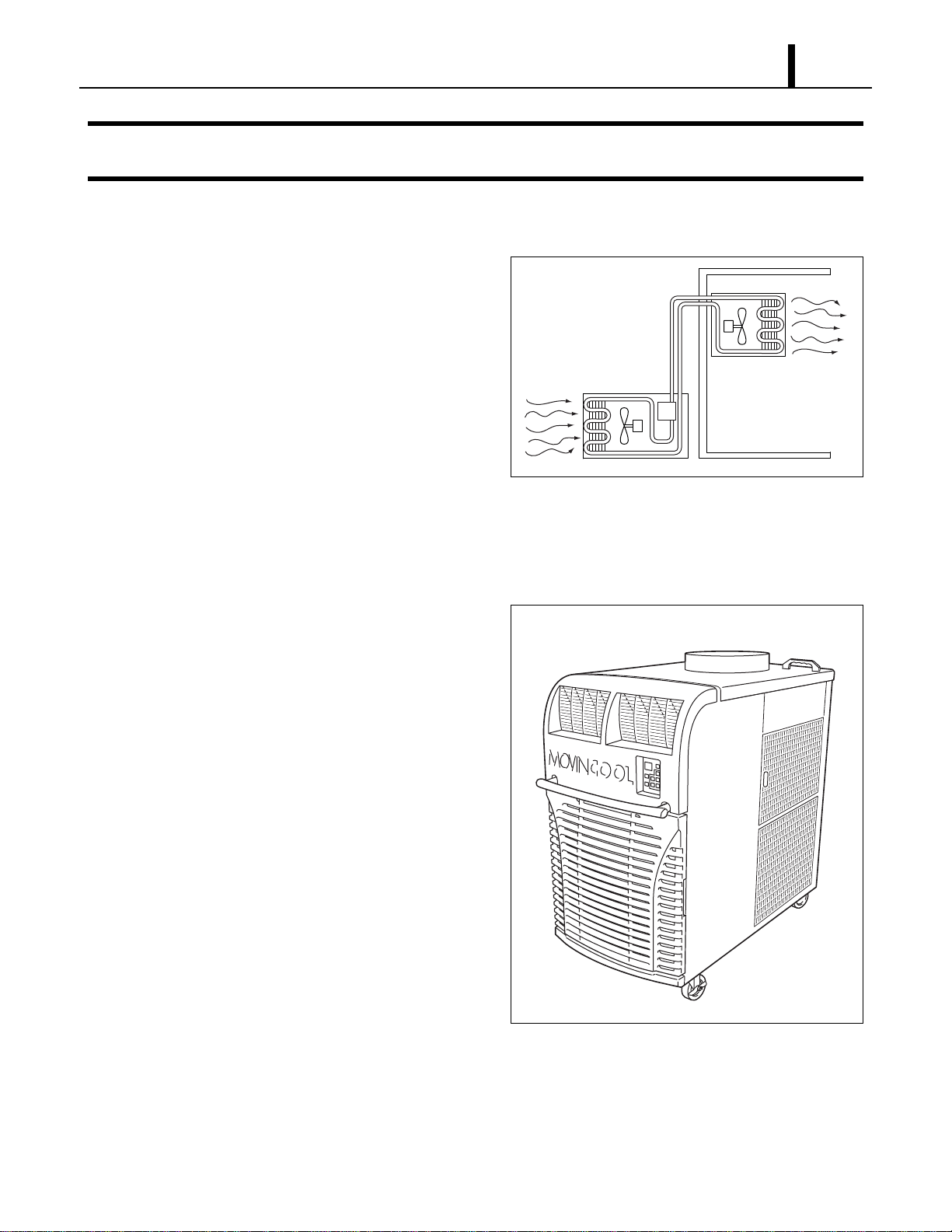
2.1 Spot Cooler
• In general, conventional air conditioners cool
the entire enclosed environment. They act as
“heat exchangers”, requiring an interior unit
(evaporator) to blow cool air into the interior
and an exterior unit (condenser) to exhaust
exchanged heat to the outdoors.
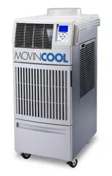
• Unlike conventional air conditioners, the
MovinCool Office Pro 36 is a spot cooler which
directs cool air to particular areas or objects.
MovinCool Office Pro 36 has the following features:
2.2 Compact Design
• The innovative design of MovinCool Office Pro
36 has resulted in one compact unit, replacing
the need for two separate units.
2.3 Easy Transportation and
Installation
• With the whole cooling system built into one
compact unit, MovinCool Office Pro 36
requires no piping and can be easily
transported and installed.
2.4 Energy Conservation
• MovinCool Office Pro 36 is economical
because it cools only the area or objects which
need to be cooled.
I000501
Condenser
(Outdoor Unit)
Evaporator
(Indoor Unit)
I001758
Operation Section
8
3. CONSTRUCTION
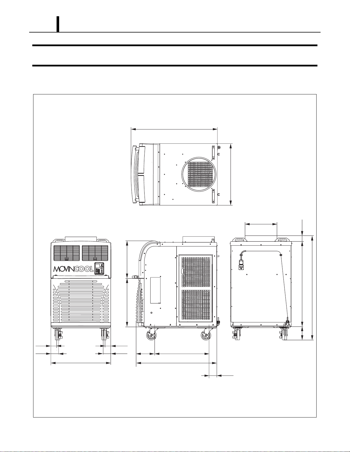
3.1 Exterior Dimensions
I002269
(3.7)
(40.0)
(27.1)(9.2)
(2.8)(2.8)
(3.8)
(3.8)
(29.8)
(Unit: inch)
(24.2)
(18.7)
(6.6)
(42.1)
(2.9)
(30.2)
(42.1)
(DIA. 15.7)
(51.7)
Operation Section
9
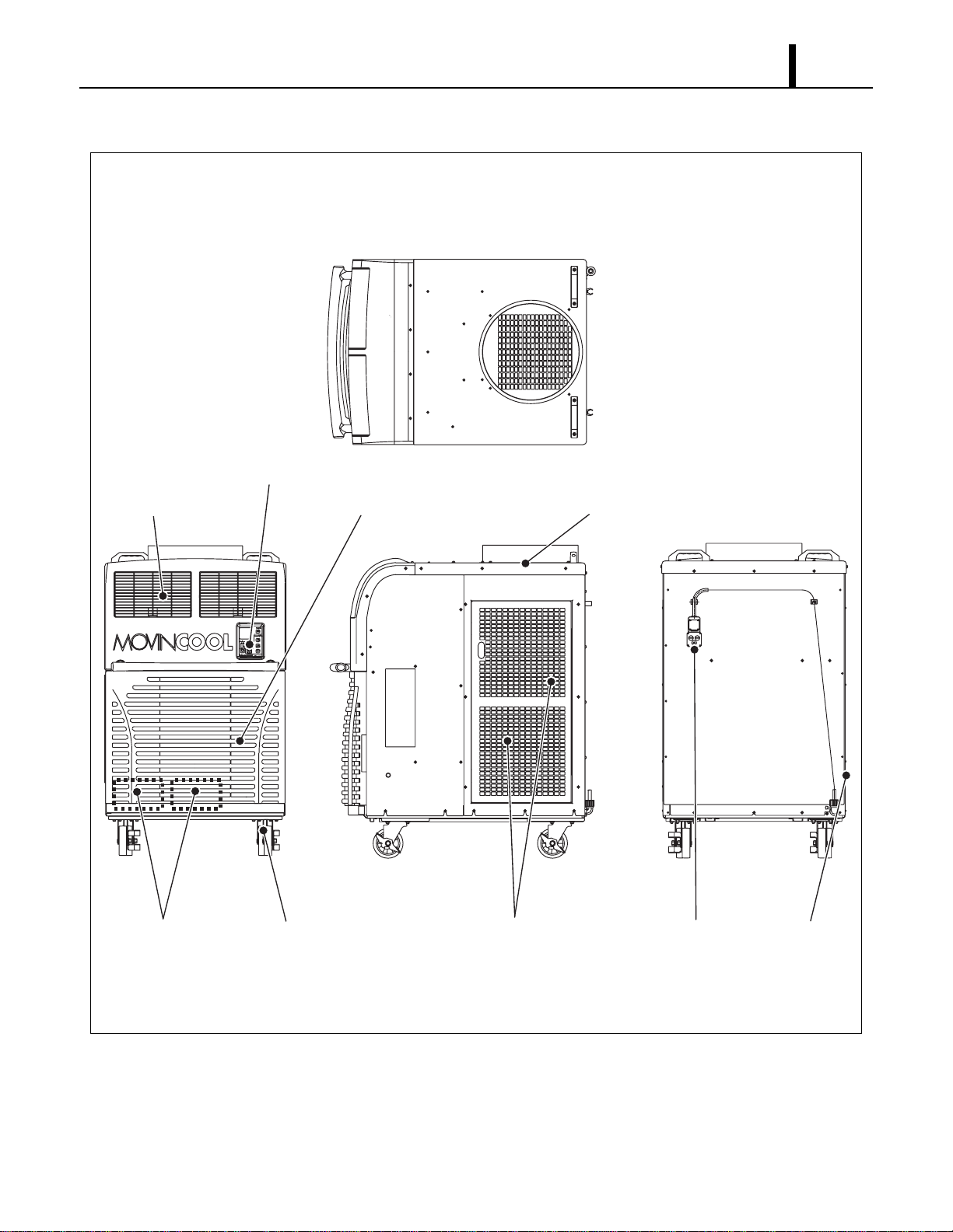
3.2 Exterior Components
I002270
Cold Air Outlet Grill Evaporator Air Inlet Grill Condenser Air Outlet Duct
Service PanelPower CordCondenser Air Inlet PanelCasterDrain Tanks
Operation Panel
Operation Section
10
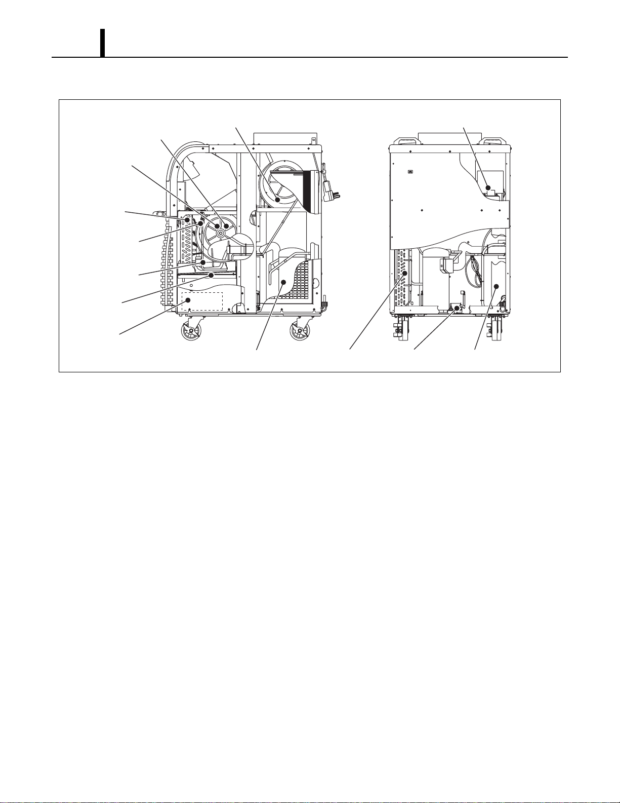
3.3 Internal Structure
3.4 Basic Construction
• The MovinCool Office Pro 36 is compact in construction because the condenser and the
evaporator are enclosed in one unit. The interior is divided into three sections. The upper front
face is equipped with the evaporator, and the lower front face contains the drain tanks and
condensate pump (Optional). The rear section contains the condenser, the compressor and the
control box.
I002271
Evaporator
Fan
(Evaporator)
Fan
(Condenser)
Fan Motor
(Condenser)
Fan Motor
(Evaporator)
(Behind Fan)
Control Box
Drain Switch
Compressor
Condensate Pump
(Optional)
Drain Pan
Capillary Tube
High Pressure
Switch
Condenser
Operation Section
11
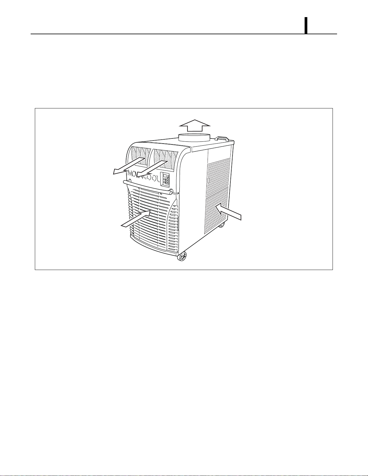
3.5 Air Flow
• Air drawn from the right side face passes through the condenser which extracts the heat. This
hot air is blown out through the upper exhaust air duct. Air taken in from the front face is cooled
by the evaporator and then blown through the cool air vent. All the air inlets are equipped with
filters, and the exhaust air duct is protected by metal grill.
3.6 Compressor and Fans
• The compressor is hermetically sealed. Two sets of a two-speed fan motor with a centrifugal fan
are used to draw air across the evaporator and condenser.
3.7 Drain Tanks
• A set of two 5.0 gal (19 L) drain tanks are supplied with the Office Pro 36. The condensate
(water) is collected into both tanks.
The drain switch activates and stops the operation when tanks reach the level of approximately
8.0 gal (30 L).
I001762
Condenser Air In
Evaporator Air In
Exhaust Air Out
Cool Air Out
Operation Section
12
4. SPECIFICATIONS
4.1 Technical Specifications
ITEM SPECIFICATIONS
Electronic Features Control Panel Electronic
Thermostat Control Electronic
Cooling Capacity
*1
Capacity-208 V/230 V 35000/36000 Btu/h (10258/10551 W)
Refrigerant Circuit Compressor Compression Type Hermetic Scroll
Motor Rated Output at 230 V 2.30 kW
Evaporator Plate Fin
Condenser Plate Fin
Refrigerant Control Capillary Tube
Refrigerant/Enclosed quantity R-410A/2.38 lb (1.08 kg)
Ventilation Equipment For
Evaporator
Fan Type Centrifugal
Max. Air Flow-high/low 990/825 CFM (1680/1400 m
3
/h)
Motor Rated Output-high/low at 230 V 0.21/0.13 kW
Max. External Static Pressure 0.6 IWG (149 Pa)
Ventilation Equipment For
Condenser
Fan Type Centrifugal
Max. Air Flow - high/low 1490/1060 CFM (2530/1800 m
3
/h)
Motor Rated Output-high/low at 230 V 0.33/0.12 kW
Max. External Static Pressure 0.5 IWG (125 Pa)
Electronic Characteristics Power Requirement 208/230 V, 1 PH 60 Hz
MIN. MAX. Voltage MIN 198 V, MAX 253 V
Current Consumption-208 V/230 V
*1
21.4/19.6 A
Total Power Consumption-208 V/230 V
*1
4.3/4.3 kW
Power Factor-208 V/230 V
*1
97/95 %
Starting Current 88 A
Recommended Fuse size 30 A
Power Cord NEMA Plug Configuration 6-30
Gauge x Length 12 AWG (3-core) x 6 ft
Signal Connection Fire Alarm Input • Dry contact type (recommended)
• No-Voltage Contact Input/Contact
resistance Less than 100 ohm
Warning Signal Output 2 A at 30 V (DC/AC) or less
(resistive load)
Net weight 427 lb (194 kg)
Operation Section
13
• Specifications are subject to change without notice.
< NOTE >
*1 :Rating Condition: 95 °F (35 °C), 60 %RH
*2 :Measured at 3.28 ft (1 m) from surface of unit.
Operating Condition Inlet air: Maximum 95 °F (35 °C), 60 %RH
Inlet air: Minimum 65 °F (18.3 °C), 50 %RH
Sound Level
*2
With Condenser Duct-high/low 65/62 dB (A)
Without Condenser Duct-high/low 67/66 dB (A)
Max. Duct Equivalent Length-Per Cold Duct Hose/Hot Duct Hose 40/60 ft (12.2/18.3 m)
Condensate Tank Capacity 5 ± 0.5 gal (19 ± 2 L)
ITEM SPECIFICATIONS

Operation Section
14
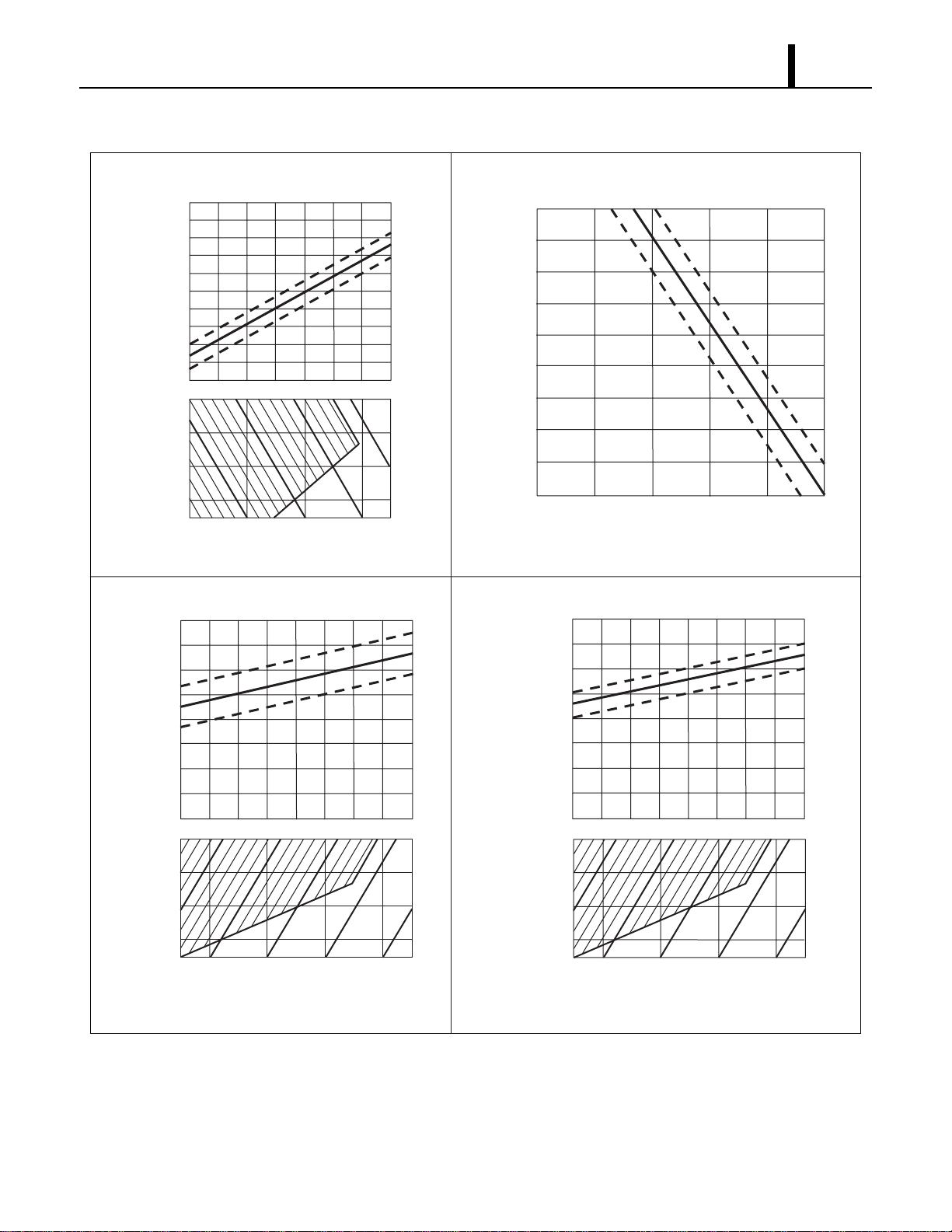
4.2 Characteristics (at 230 V)
I001764
45
40
30
35
25
20
10
20
25
15
5
<Cooling Capacity Curve><Cool Air Temperature Difference Curve>
55(13)
54(12)
52(11)
50(10)
48(9)
46(8)
45(7)
43(6)
41(5)
68(20)
77(25)
86(30)
95(35)
39(4)
Temperature °F (°C)
Dry Bulb Temp. °F (°C)
Dry Bulb Temp. °F (°C)
Dry Bulb Temp. °F (°C)
Wet Bulb Temp. °F (°C)
Wet Bulb Temp. °F (°C)
(25)
77
(20)
68
(35)
95
(30)
86
(15)
59
(10)
50
Cooling Capacity (x10
3
Btu/h)
Relative Humidity (%)
30 4050607080
Current Consumption (A)
Power Consumption (kW)
<Power Consumption Curve><Current Consumption Curve>
5.0
4.0
3.0
2.0
1.0
68(20)
77(25)
86(30)
95(35)
68(20)
77(25)
86(30)
95(35)
(25)
77
(20)
68
Wet Bulb Temp. °F (°C)
(35)
95
(30)
86
(25)
77
(20)
68
Operation Section
15
4.3 Characteristics (at 208 V)
I001765
45
40
30
35
25
20
10
20
25
15
5
<Cooling Capacity Curve><Cool Air Temperature Difference Curve>
68(20)
77(25)
86(30)
95(35)
Cooling Capacity (x10
3
Btu/h)
Relative Humidity (%)
30 40 50 60 70 80
Current Consumption (A)
Power Consumption (kW)
<Power Consumption Curve><Current Consumption Curve>
5.0
4.0
3.0
2.0
1.0
55(13)
54(12)
52(11)
50(10)
48(9)
46(8)
45(7)
43(6)
41(5)
68(20)
77(25)
86(30)
95(35)
39(4)
Temperature °F (°C)
Dry Bulb Temp. °F (°C)
Wet Bulb Temp. °F (°C)
(25)
77
(20)
68
(15)
59
(10)
50
68(20)
77(25)
86(30)
95(35)
Dry Bulb Temp. °F (°C)
Dry Bulb Temp. °F (°C)
Wet Bulb Temp. °F (°C)
(35)
95
(30)
86
(25)
77
(20)
68
Wet Bulb Temp. °F (°C)
(35)
95
(30)
86
(25)
77
(20)
68

Operation Section
16
5. REFRIGERANT SYSTEM
5.1 Refrigerant System Construction
The component parts of the refrigerant system include the following:
• Compressor, Evaporator, Condenser, Capillary tube, High Pressure Switch
These parts are all connected by copper tubing. All the connections have been brazed.
I001766
Condenser
Condenser
Fan
Evaporator
Fan
Evaporator
Compressor
Capillary
Tubes
Flow of Refrigerant
Condenser
Evaporator
Condenser
Condenser
Outlet Pipe
Compressor
Suction Pipe
Capillary Tube
Condenser
Inlet Pipe
Compressor
Discharge Pipe
Compressor
Evaporator
Evaporator
Pipe
Capillary
Tube
Evaporator
Outlet Pipe
Operation Section
17
5.2 Compressor
• The compressor used for the unit is hermetically sealed. The compressor and the compressor
motor are in one casing.
(1) Compressor theory of operation
• The scroll utilizes an involuted spiral which, when matched with a mating scroll form, generates
a series of crescent-shaped gas pockets between the two members. During compression, one
scroll remains stationary (fixed scroll) while the other form (orbiting scroll) is allowed to orbit (but
not rotate) around the first form. As this motion occurs, the pockets between the two forms are
slowly pushed to the center of the two scrolls while simultaneously being reduced in volume.
When the pocket reaches the center of the scroll form, the gas, which is now at a high pressure,
is discharged out of a port located at the center. During compression, several pockets are being
compressed simultaneously, resulting in a very smooth process. Both the suction process (outer
portion of the scroll members) and the discharge process (inner portion) are continuous.
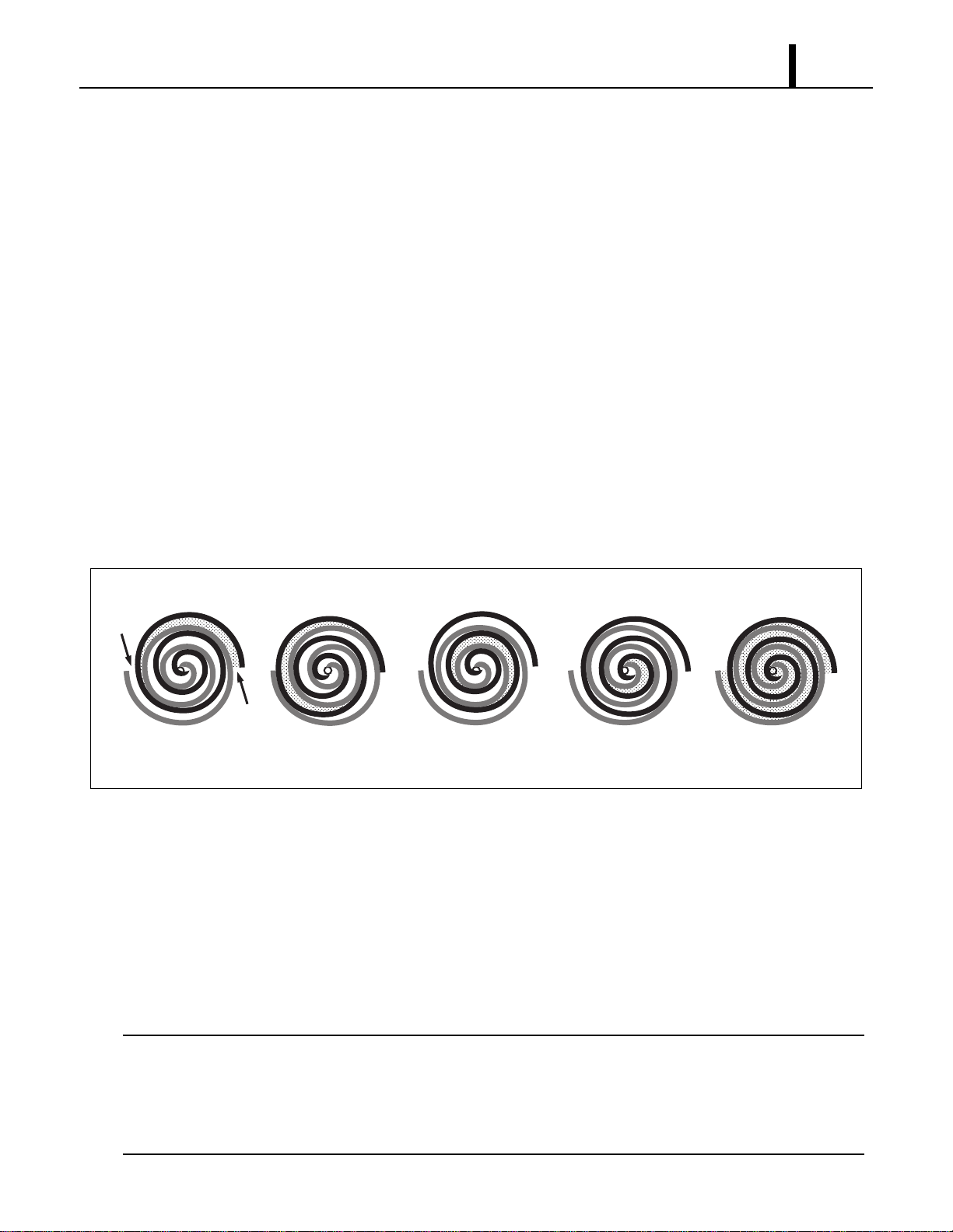
(2) Compressor operation
1) Compression in the scroll is created by the interaction of an orbiting spiral and a stationary spiral.
Gas enters the outer openings as one of the spirals orbits.
2) The open passages are sealed off as gas is drawn into the spiral.
3) As the spiral continues to orbit, the gas is compressed into two increasingly smaller pockets.
4) By the time the gas arrives at the center port, discharge pressure has been reached.
5) Actually, during operation, all six gas passages are in various stages of compression at all times,
resulting in nearly continuous suction and discharge.
< NOTE >
When the compressor shuts off, the compressor motor may run backward for a moment or two
until internal pressures is equalized. This has no effect on compressor durability but may cause
an unexpected sound after the compressor is turned off and should not be diagnosed as a
malfunction.
I001767
1㧕 3㧕 4㧕 5㧕2㧕
Operation Section
18
5.3 Condenser
• The condenser is a heat exchanger with copper tubes that are covered with thin aluminum
projections called plate fins.
• Heat is given off and absorbed by air being pulled across the condenser fins by the centrifugal
fan and then expelled through the exhaust air duct.
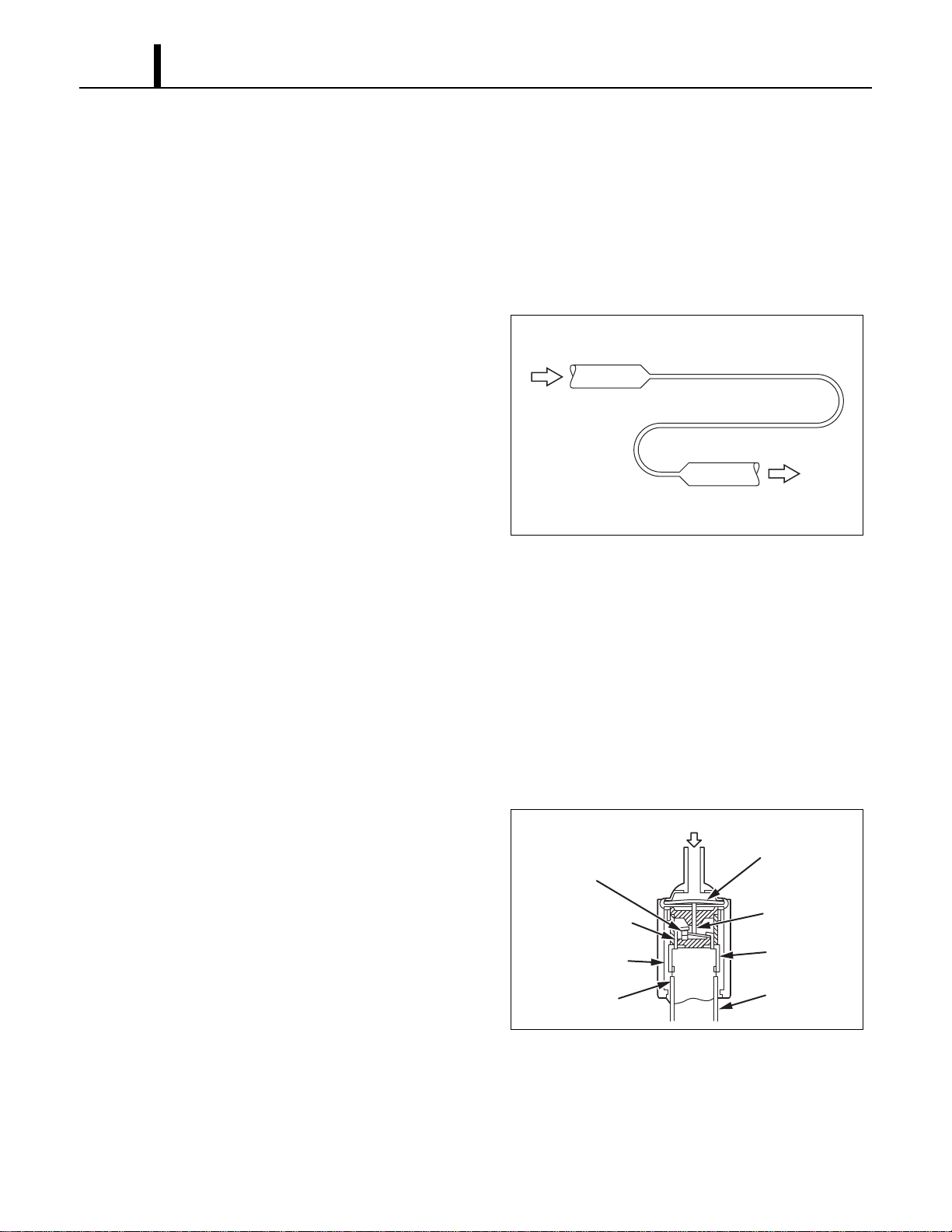
5.4 Capillary Tube
• The capillary tube is a long thin tube utilizing
line flow resistance to serve as an expansion
valve. The length and the inner diameter of the
capillary tube are determined by the capacity of
the refrigeration system, specified operating
conditions, and the amount of refrigerant. The
capillary tube causes the high pressure, high
temperature liquid refrigerant sent from the
condenser to expand rapidly as the refrigerant
is sprayed out through the fixed orifice in the capillary tube. As a result, the temperature and
state of the refrigerant becomes low and mist-like respectively, causing it to evaporate easily.
5.5 Evaporator
• The evaporator, like the condenser, is a heat exchanger covered with plate fins. Heat is removed
from the air being pulled across the evaporator by the centrifugal fan and the resulting cool air
is expelled through the cool air vent.
5.6 High Pressure Switch
• The high pressure switch prevents the
condenser and compressor from being
damaged by excessively high pressure in the
high pressure line of the refrigeration cycle.
The switch is normally closed. The snap disk
responds to the variations in pressure and, if
pressure is abnormally high, the snap disk
moves down to push the pin down, causing the
internal contacts to open. This interrupts the
ground signal at the control board (J104 connector) which turns the compressor off.
• Possible causes of this trouble include:
- The condenser air filter is dirty, restricting air flow.
- The condenser blower is defective.
I001887
High Temp./High Pressure
Liquid Refrigerant
Low Temp./Low Pressure
Gas and Liquid Mixture
I001768
Pressure of Refrigerant
Movable Point
Snap Disk
Pin
Terminal
Lead Wires
Stationary Point
Molding by Resin
Case
Operation Section
19
6. ELECTRICAL SYSTEM
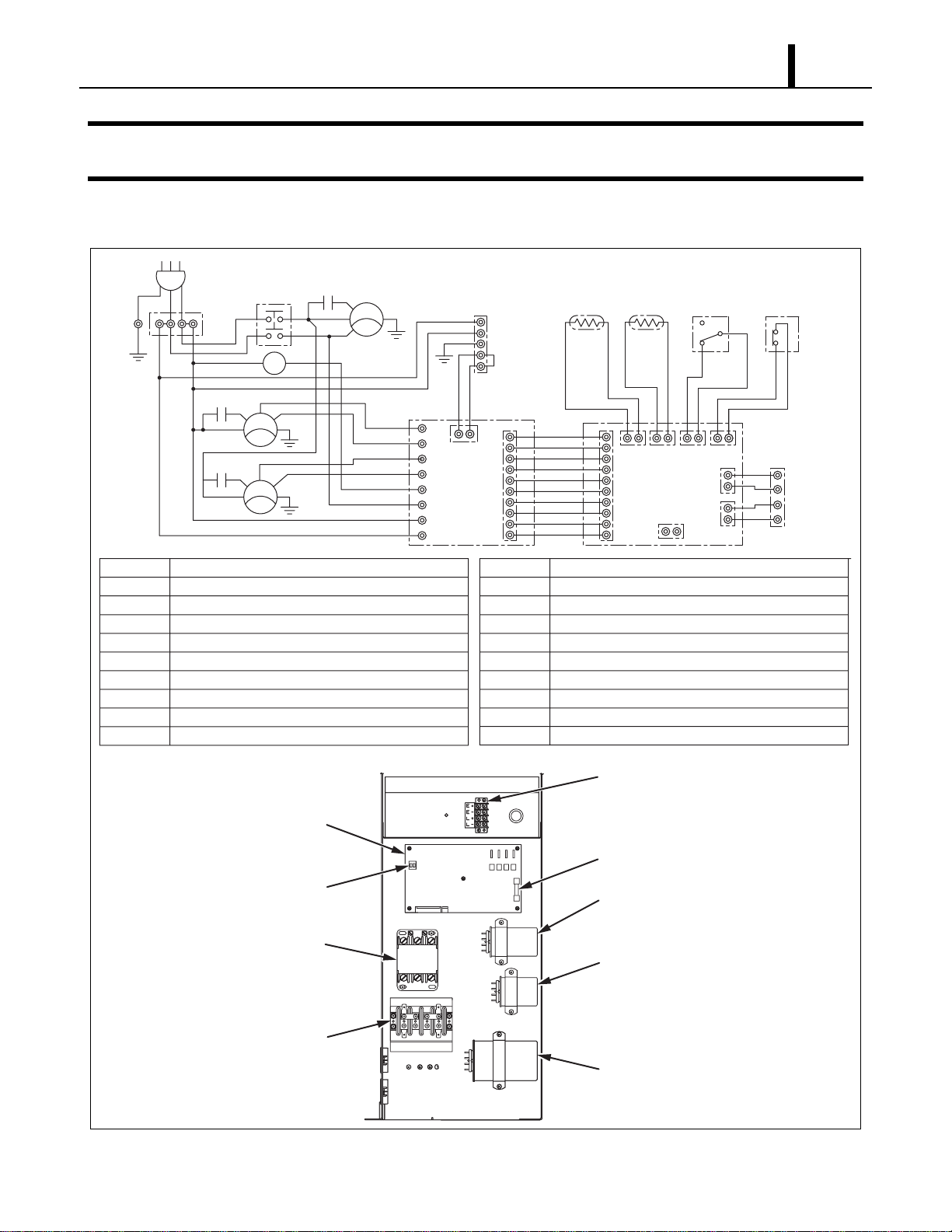
6.1 Circuit Diagram and Control Box
I001769
AC 208/230 V 1φ 60 Hz
AP
G
G
G
G
T1
TB1
L1
HI
HI
LO
LO
MF2
T1
L3
MCC
MCC
MC
CN RTH THS DS
CB
HPRS
TB2
L-
J106
J108
J105
J101 J102 J103 J104
J201
L+
E-
E+
3
2
1
Jumper
Line
IOLC
IOLF
MF1
IOLF
CC
12
CF2
12
CF1
12
G
G
T3
T RR1
J9
J10
RB
J8
J7
J6
J5
J4
J3
J2
J1
AP
TB1
TB2
CB
R B
MF1
MF2
MC
CF1
CF2
Attachment Plug
Terminal Block
Terminal Block
Control Board
Relay Board
Condenser Fan Motor
Evaporator Fan Motor
Compressor Motor
Capacitor for Condenser Motor
Capacitor for Evaporator Motor
CC
IOLF
IOLC
DS
THS
R TH
G
HPRS
CN
MCC
Capacitor for Compressor
Inner Overload Relay of Fan Motor
Inner Overload Relay of Compressor
Full Drain Warning Switch
Freeze Protection Thermistor
Room Thermistor
Grounding
High Pressure Switch
Connector for Option Condensate Pump
Relay for Compressor and Condenser Fan Motor
Terminal Block
(Signal Connections)
Relay Board Fuse
Relay Board
Relay
Terminal Block
Dip Switch
Fan Capacitor
(Condenser)
Fan Capacitor
(Evaporator)
Compressor
Capacitor
TB2
TB1
Operation Section
20
6.2 Basic Operation of The Office Pro 36 Electrical Circuit
• There are two basic components used to control the operation of the Office Pro 36 electrical
system:
- Control panel assembly
- Control box
• The control panel assembly contains the control panel, control board (with inputs for the freeze
and room temperature thermistors), drain switch, high pressure switch and a microprocessor.
(1) Fan mode
High Fan Mode
• When the FAN MODE button on the control panel is pressed, the microprocessor turns on “FAN
HI” “COOL OFF” indication of LCD and activates both the fan on relay and fan mode relay. This
sends line voltage (208/230 VAC) from the fan on relay to the N.O. (normally open) contacts of
the fan mode relay. This output is connected to the J8 terminal (relay board) where the high
speed wire of the fan motor is connected.
• When this button is pressed again, fan turns to low mode (see below). Press again, fan stops.
Low Fan Mode
• When the FAN MODE button on the control panel is pressed again, the microprocessor turns on
“FAN LO” “COOL OFF” indication of LCD and activates both the fan on relay and fan mode relay.
This sends line voltage (208/230 VAC) from the fan on relay to the N.C. (normally closed)
contacts of the fan mode relay. This output is connected to the J7 terminal (relay board) where
the low speed wire of the fan motor is connected.
• When this button is pressed again, fan stops.
(2) Cool mode
• In addition to fan mode (as described above), when the COOL ON/OFF button on the control
panel is pressed, the microprocessor turns on “COOL ON” indication of LCD and if the
temperature set point is less than the current room temperature, activates the compressor relay
(relay board) after 120 sec delay. This sends line voltage (208/230 VAC) to the J4 terminal (relay
board) where compressor wire is connected. Then compressor turns on for Cooling Operation.
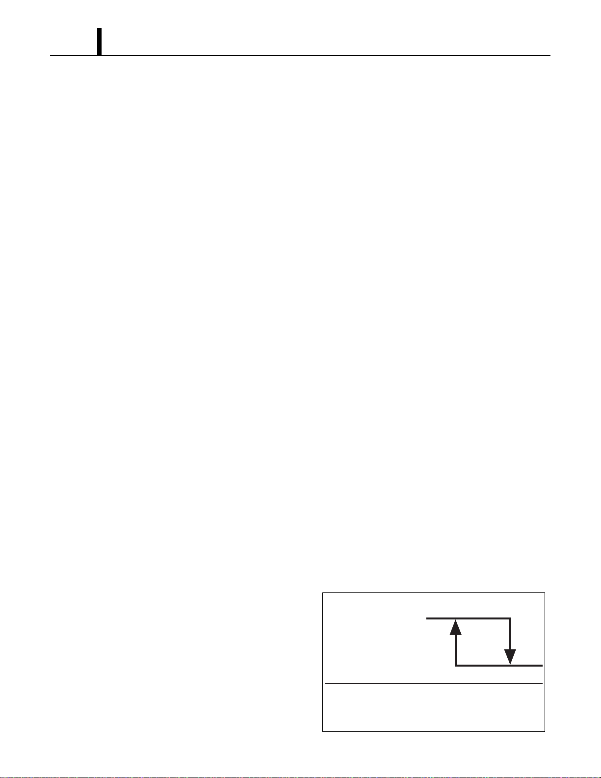
• Condenser fan mode is automatically switched
depending on room temperature. When room
temperature is approximately. 79 °F (26 °C) or
greater, fan mode is switched LO to HIGH.
When room temperature is approximately.
75 °F (24 °C), fan mode is switched HI to LO.
I001770
75 °F
(24 °C)
Room Temperature
(LO)
(High)
Condenser Fan
79 °F
(26 °C)
Operation Section
21
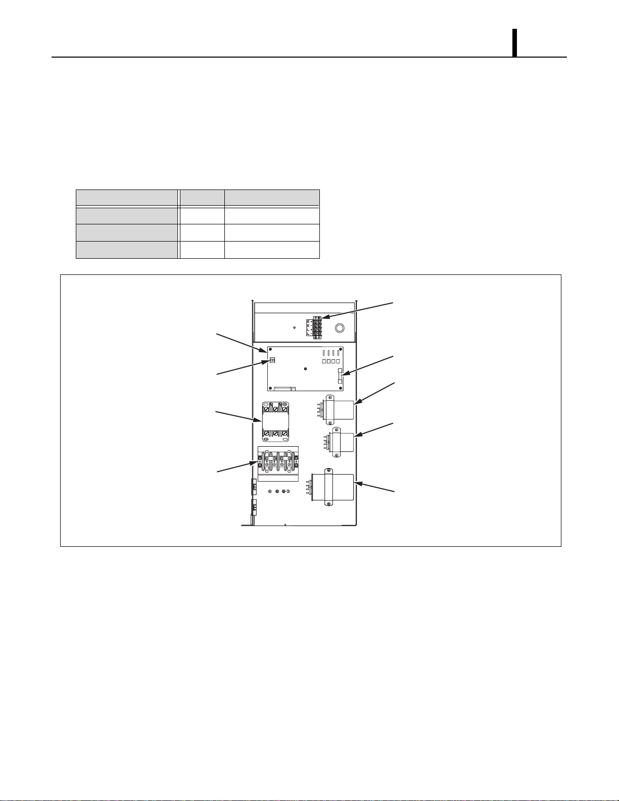
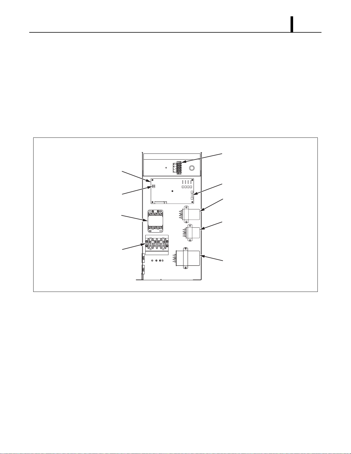
6.3 Control Box
(1) Capacitors
• The capacitors are used to temporarily boost the power output available to the fan motor and
the compressor at start-up.
• The specifications of each capacitor are listed below:
Capacitor Application Voltage Rating Capacitance
Evaporator Fan Motor 440 VAC 5 µF
Condenser Fan Motor 440 VAC 15 µF
Compressor 370 VAC 55 µF
I001771
Terminal Block
(Signal Connections)
Relay Board Fuse
Relay Board
<Control Box>
Relay
Terminal Block
Dip Switch
Fan Capacitor
(Condenser)
Fan Capacitor
(Evaporator)
Compressor
Capacitor
TB2
TB1
Operation Section
22
(2) Relay board
• The relay board receives signals and outputs
from the control board that contains a
microprocessor. The relay board contains the
compressor, fan on and fan mode (speed)
relays.
• It also contains a step-down transformer that
converts the line voltage (208/230 VAC) to
12 V.
• This 12 V is then converted from AC to DC and
used for relay coil activation. The 12 V (DC) power is sent to the control panel assembly where
it is further reduced to 5 V for the system logic.
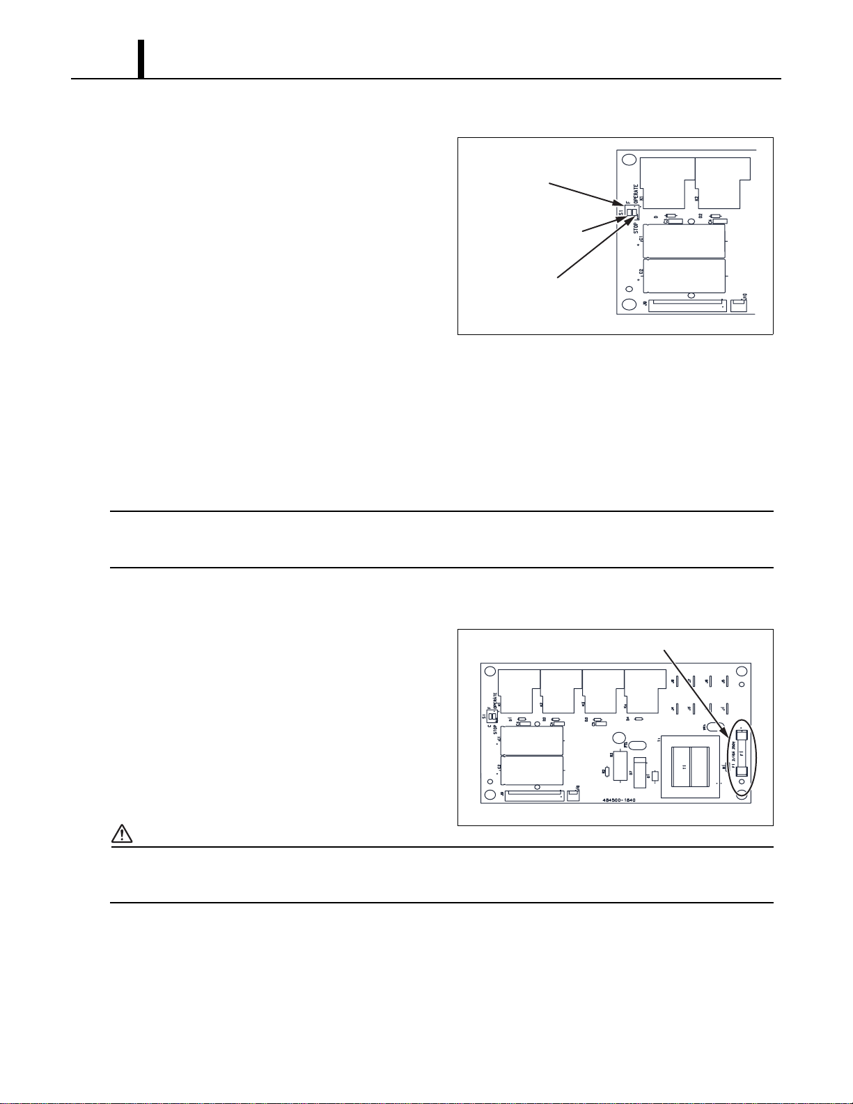
• The relay board also contains the DIP switch.
• The DIP switch is used to change the fan mode operation from stop to operate and change both
the set point and room temperature display from Fahrenheit to Celsius.
< NOTE >
The relay board must be serviced as a complete assembly. It has only one serviceable
component, the fuse. (see below)
(3) Relay board fuse
• This fuse provides protection against damage
to the step-down transformer. It must be
replaced with the exact type of fuse or an
equivalent.
Specifications:
- 2/10 A, 250 V
CAUTION
Failure to use the exact type of fuse could result in damage to the unit and/or to components. It
could also void the warranty of the unit.
I001772
Dip Switch
<Dip Switch>
Fan Mode Control
Switch
(STOP
⇔
OPERATE)
Temperature Scale
Display Switch
(°C
⇔
°F)
I001773
Fuse
<Relay Board>
Operation Section
23
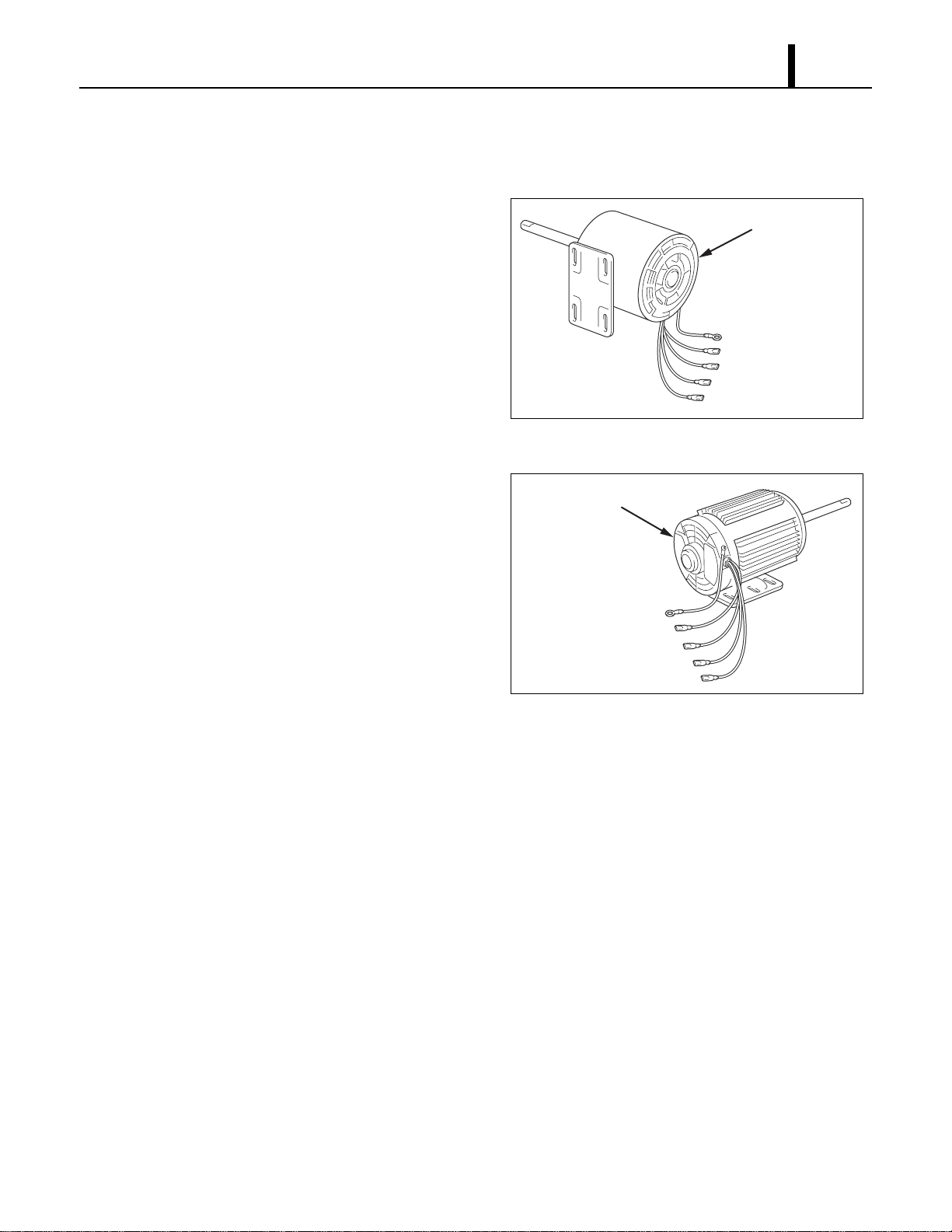
6.4 Fan Motor
(1) For evaporator
• The fan motor is a single phase, induction type
two-speed motor.
Specifications:
- Rated Voltage: 230 V, 60 Hz
- Rated Output: High-210 W, Low-129 W
(2) For condenser
• The fan motor is a single phase, induction type
two-speed motor.
Specifications:
- Rated Voltage: 230 V, 60 Hz
- Rated Output: High-330 W, Low-120 W
I001774
Evaporator Fan Motor
Ground (Green/Yellow)
J7 Low (Red)
CF22 (Brown/White)
CF21 (White)
J8 High (Black)
I001775
Condenser Fan Motor
Ground (Green/Yellow)
J5 Low (Red)
CF12 (Brown/White)
CF11 (White or Orange)
J6 High (Black)
Operation Section
24
6.5 Compressor Motor
• The compressor motor is a single-phase motor and is contained within the same housing as the
compressor.
Specifications:
- Rated Voltage: 208/230 V, 60 Hz
- Rated Output : 2300 W (at 230 V)
< NOTE >
An internal overload relay is used to protect the fan motors and the compressor motor. This relay
is built into the fan motors and compressor motor. It interrupts the flow of current when there is an
over current situation or if abnormally high temperature builds up in the fan motors and
compressor motor.
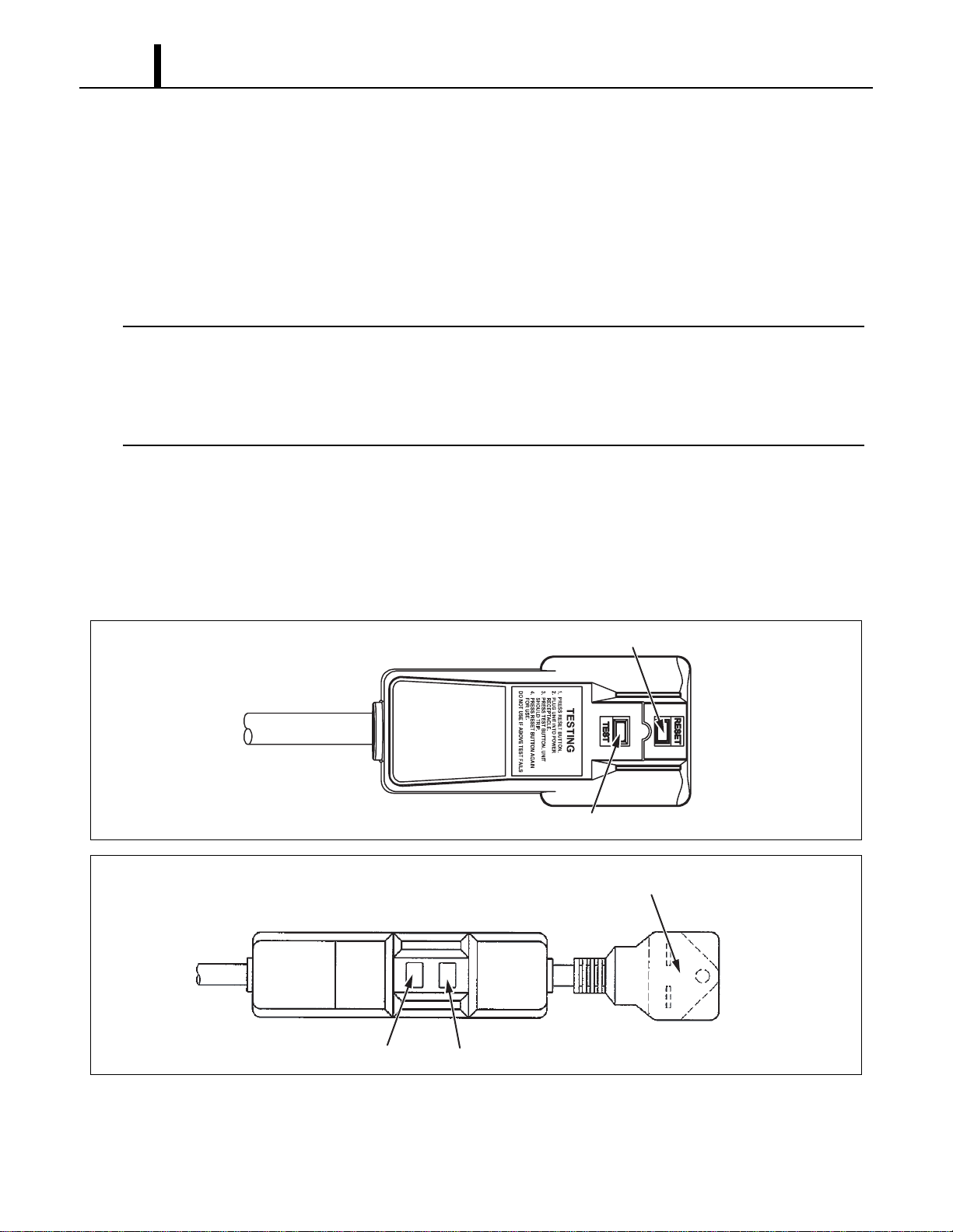
6.6 Power Cord with LCDI
• Office Pro 36 is equipped with a UL approved LCDI cord and an approved NEMA plug
configuration (6-30). The appropriate outlet must be used for this plug type. LCDI is used for
monitoring leakage current. Once leakage current is detected, LCDI de-energizes the unit.
I002284
Reset Button
Test Button
<Type 1>
I002285
<Type 2>
Molded Plug, NEMA 6-30P
Reset ButtonTest Button
Operation Section
25
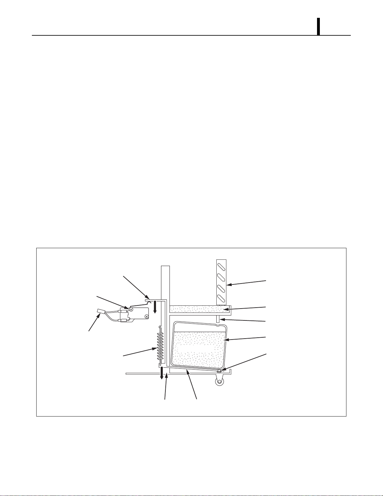
6.7 Drain Switch
• The Office Pro 36 is equipped with a drain tank switch. When the drain tanks accumulate
approximately 8.0 gal (30 L) of condensate (water) in the drain tanks, the drain tank switch sends
a signal to the microprocessor. The microprocessor stops all operation of the unit, flashes the
"TANK FULL” LED, indicates "TANK FL” on the LCD and closes the contact of output signal.
• This system utilizes a 0.1 A, 125/250 VAC micro-switch for this function. When drain water
accumulates approximately 8.0 gal (30 L) in the drain tanks, the drain tank base plate, which is
supported at its fulcrum, is pushed down in the arrow direction as shown in the figure below.
• When the drain tank base plate is forced down, the top of the drain tank base plate turns off the
contacts #1-#2 of the micro switch. This causes the ground signal at the J103 connector of the
control panel assembly to go open. When the microprocessor detects this event, it shuts the unit
off, flashes the “TANK FULL” LED, indicates “TANK FL” on the LCD and closes the contact of
output signal.
• When the drain tanks are removed (or the drain tanks are emptied), the top of the drain tank
base plate returns to its original position from the tension of the coil spring. Then contacts #1-#2
of the drain tank switch close. This provides a ground to the microprocessor through the J103
connector.
I002230
2
NC
C
1
DS2
DS1
Evaporator
Drain Pan
Drain Tube
Drain Tanks
Fulcrum
Drain Water
Top Base Plate
Base Plate
Base
Drain Switch
Spring
To J103

Operation Section
26
(1) How to re-start the unit
• If the LCD indicates “PROGRAM ON”, press the COOL ON/OFF button to continue running the
program. If the LCD indicates “PROGRAM ON” continuously (program activated), no further
steps are necessary. If no program exists or the program was deactivated, press the FAN MODE
button or the COOL ON/OFF button. The unit returns to the previous temperature set point.
6.8 Condensate Pump Kit (optional)
• The Office Pro 36 model comes standard with 2 drain tanks, which collect the water that forms
on the evaporator during normal cooling operation. If the unit is required to operate continuously
without periodic emptying of this tank, a condensate pump may be needed. A condensate pump
kit is available for the Office Pro 36 model.
6.9 Automatic Restart after Power Interruption
• The program within the microprocessor of the Office Pro 36 contains a feature that automatically
restarts the unit after power is lost and then regained. The unit also has memory in order to
return itself back to the operating mode (either manual or preset program) it was in prior to the
loss of power. All preset programs are retained in the memory in the event power loss occurs.
6.10 Compressor Protection
• There is a time delay program within the microprocessor. This prevents a heavy load from being
applied on the compressor motor when restarting the unit cool mode after a very short period of
time. This delay is in effect any time when the compressor is turned on by either the COOL
ON/OFF button, temperature set point (thermostatic control), power interruption restart or
condensate pump (optional) operation.
Specifications:
Time delay
- 120 ± 20 sec
6.11 Temperature Control
• The compressor operation cool mode is controlled by the microprocessor which receives input
signals from the room temperature thermistor (evaporator inlet air) and the setting of the
temperature set point. The temperature set point (desired room temperature) can be adjusted
by pressing the U/V buttons on the control panel. The adjustment range of the temperature set
point is 65 °F to 90 °F (18 °C to 32 °C).
Operation Section
27
6.12 Fan Mode Control Switch
• The fan motor operation is controlled by relays on the relay board through a microprocessor in
the control panel assembly. The fan program in the microprocessor can be changed by a DIP
switch on the left side of the relay board located in the control box.
• There are two settings:
(1) Cool to stop
• When the DIP switch is set in the downward or STOP position, the microprocessor controls the
fan motor using the same room temperature thermistor that it uses to control the compressor. In
this case, both the fan and the compressor stop when the microprocessor receives a sufficiently
low intake air (room temperature) signal from the thermistor (equal to or less than the set point).
When the temperature increases (exceeds the set point) the microprocessor restarts the fan and
compressor automatically. However, if the unit has been off for less than 120 sec, the fan starts
before the compressor (time delay feature).
(2) Cool to operate
• When the DIP switch is set to the upward or OPERATE position, the microprocessor controls
the fan operation using control panel inputs only. The fan operates continuously during fan only
and cool modes. (This is the factory default setting.)
6.13 Temperature Scale Display Switch
• When the DIP switch is set in the down or “°C” position, the set point and room temperature are
displayed in degrees Celsius. “°C” is indicated on the LCD. When the DIP switch is set in the up
or “°F” position, the set point and room temperature are displayed in degrees Fahrenheit . “°F”
is indicated on the LCD. (This is the factory default setting.)
Operation Section
28
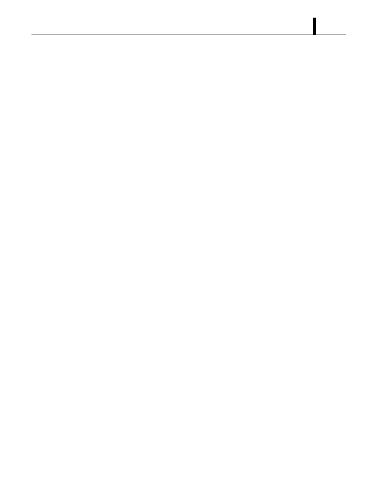
6.14 Warning Signal Connection (Output Signal Terminal L+ and L-)
• The controller is equipped with a warning signal output relay type (Form C, normal open dry
contact) which can be used to monitor the failure condition.
Relay contactor is closed when the following condition has occurred:
-Tank Full
- Temperature sensor fails
- High pressure switch error
• The relay output contactor is rated 2 A at 30 VDC or 2 A at 30 VAC (resistive load) and it is
compatible with various warning devices such as alarm speaker, light indicators, etc.
Connecting warning signal from controller
- Remove service panel from the rear of the unit.
- Squeeze the inner latches and push out the black cap from inside the panel. (See drawing of
cap and inner latch shapes.)
- Use recommended warning signal wire size from 16 AWG to 26 AWG or a solid wire, or 16
AWG to 22 AWG for a stranded wire with ring terminal for #6 stud size.
- Connect warning device to terminal L+ and L- according to its polarities.
6.15 Fire Alarm Control Panel Connection (Input Signal Terminal E+ and E-)
• The controller is equipped with a normal open input signal, which can be connected directly from
the fire alarm control panel. When receiving the signal from the fire alarm control panel, the unit
turns off and does not turn back until it has been reset.
Connecting fire alarm control panel to controller
- Remove service panel from the rear of the unit.
- Squeeze the inner latches and push out the black cap from inside the panel. (See drawing of
Cap and inner latch shapes.)
- Use recommended warning signal wire size from 16 AWG to 26 AWG for a solid wire, or 16
AWG to 22 AWG for a stranded wire with ring terminal for #6 stud size.
- Connect warning device to terminal E+ and E- according to its polarities.
I001888
<Cap>
Latch
Input Signal
Terminals
Output Signal
Terminals

Repair Section
29
7. TROUBLESHOOTING
7.1 Troubleshooting
• Before troubleshooting the system, the following inspection should be performed.
(1) Inspection of power source voltage
• Check the voltage of the power source.
- Single phase 208/230 V (60 Hz)
• Check the operation and condition of the fuse or circuit breaker in the power source.
(2) Inspection of air filters
• Remove the air filters and check the element. If the element is dirty, wash it as described in the
OPERATION MANUAL supplied with the unit.
(3) Inspection of drain tanks
• Make sure tanks are fully drained.
The following pages (page 30 to 37) are self-diagnostic codes and troubleshooting information. Detailed
information is contained in the OPERATION MANUAL supplied with the unit.
Repair Section
30
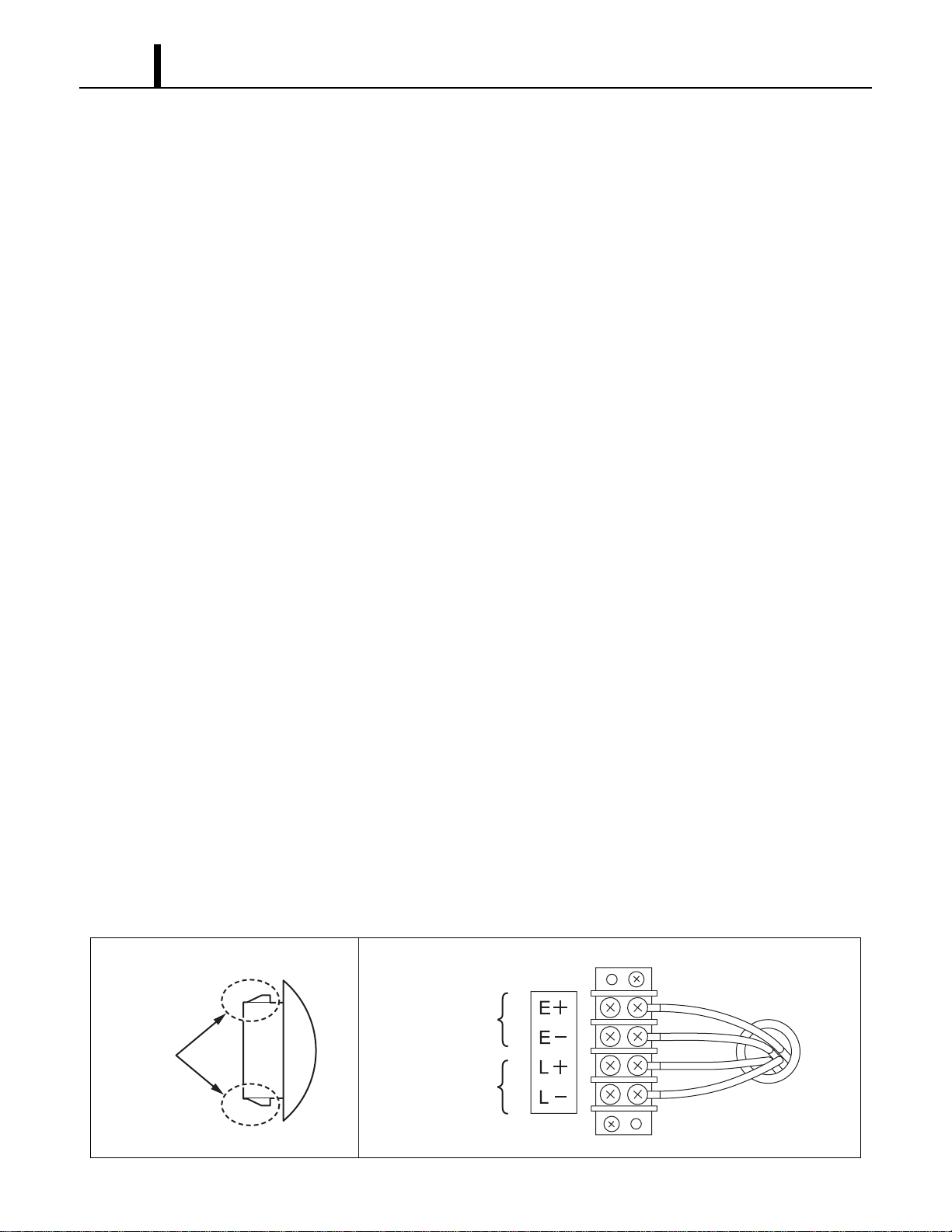
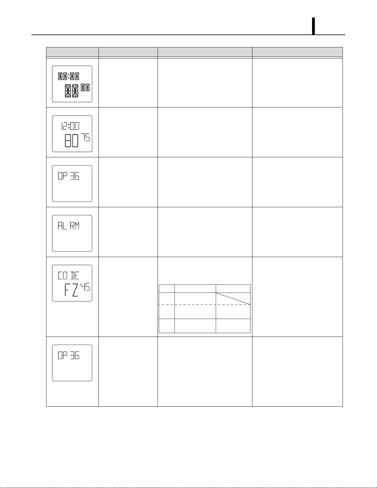
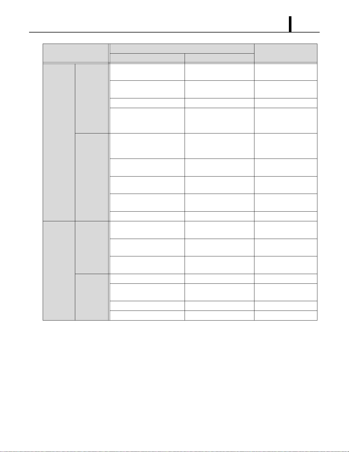
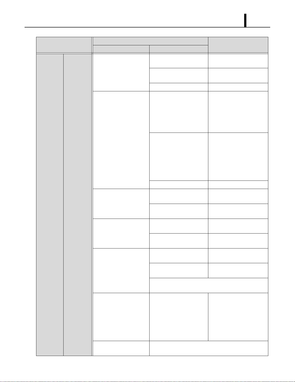
7.2 Self-Diagnostic Codes
• Self-diagnostic codes are displayed on the control board under the following conditions and
clear method is as follows.
LCD Display Description Condition Reset/Remedy
Drain tanks are full When the drain tanks are filled with
drain water.
(“TANK FL” LED flashes and signal
output (J106) turns on.)
1)Drain away.
(LCD indicates “TANK”)
2)Press ON/OFF button.
Condensate pump
problem
When (optional) condensate pump
is damaged or broken.
(J8 input of relay board turns to
open and signal output (J106) turns
on.)
1)Fix the condensate pump.
2)Reset the system.
To RESET: Press ON/OFF and
HI/LO buttons on the control box
simultaneously for 5 sec.
Defect (short or open)
of room thermistor
When room thermistor (connecting
to J101) becomes short or open.
(Signal output (J106) turns on.)
Disconnect and reconnect the
room thermistor.
If it doesn’t work, then change it.
Defect (short or open)
of freeze protection
thermistor
When freeze protection thermistor
(connecting to J102) becomes short
or open.
(Signal output (J106) turns on.)
Disconnect and reconnect the
freeze protection thermistor.
If it doesn’t work, then change it.
Show running hours Press ON/OFF and V buttons
simultaneously for 3 sec, total
operation hours of compressor is
indicated by 6-digit (hours).
Example in left: 807 h
After 5 sec., display goes back to
normal mode.
TU
AM
F
SET TEMP
HI
ON
COOL
FAN
F
SET TEMP
HI
ON
COOL
FAN
F
SET TEMP
HI
ON
COOL
FAN
F
SET TEMP
HI
ON
COOL
FAN
F
SET TEMP
HI
ON
COOL
FAN
Repair Section
31
Show LCD and LED
all on mode
Press HI/LO and U buttons
simultaneously for 3 sec.
(To check LCD segments and LED
display.)
After 5 sec., display goes back to
normal mode.
Key lock mode (LCD
displays “LOCKED”.)
Press ENTER and SET CLOCK
buttons simultaneously for 5 sec.
Press ENTER and SET CLOCK
buttons simultaneously for 5 sec
again to cancel the key lock mode.
Indication of model
name
Press ENTER and SET CLOCK
buttons simultaneously for 5 sec or
turn on.
Reset to normal display
automatically after 5 sec.
Detection of unit stop
signal from fire alarm
system
Press input signal from fire alarm
becomes on.
(Unit stops, output signal (J106)
turns on and buzzer sounds.)
1)After input signal turns off.
2)Reset the system.
To RESET: Press ON/OFF and
HI/LO buttons on the control box
simultaneously for 5 sec.
Indication of service
code
Press ON/OFF and U buttons
simultaneously for 3 sec. Indication
contents is as follows.
1)See page 34 to 36.
2)Press ON /OFF button.
Change model setting For installing new controller PCB, if
a different model name appears
when the unit is reset or turned on,
change model name according to
the correct procedure.
1)While pressing U and V
buttons, plug the power cord.
<Condition>
LCD indicates current setting
model name and buzzer sounds.
2)After setting the model type by
pressing U and V button,
unplug the unit.
LCD Display Description Condition Reset/Remedy
START
STOP
CLOCK
MO TU WETHFR
AM
F
C
F
C
PROGRAM
LOCKED
ON
PM
SA SU
SET TEMP
ROOM TEMP
HI
LO
ON
OFF
COOL
FAN
TU
AM
F
LOCKED
SET TEMP
HI
ON
COOL
FAN
LCD
DF
FZ
OD
Description
Value
Defrost status
Evap. out pipe
temperature
26
⇔
109F
(“26”
⇔
“
X9
”)
Outdoor
temperature
0 (“00”)
Repair Section
32
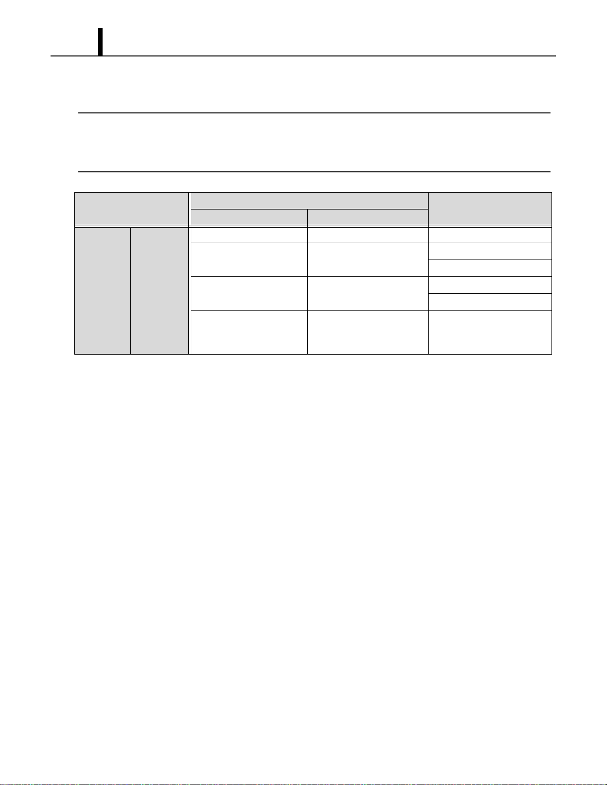
7.3 Troubleshooting Chart
• To accurately troubleshoot the problem, it is important to carefully confirm the nature of the
problem. Typical problems are:
- Insufficient cooling.
- Unit does not start (operate).
- Overflow of drain water.
- Abnormal noise or vibrations.
- Others.
(1) Insufficient cooling
• Cooling system problem generally results from electrical or mechanical components such as fan
motor, compressor, control switch.
< NOTE >
•There is a possibility of insufficient cooling due to clogging of the air filter. So make sure to first
check if the air filter is clogged or not.
•Check the power supply because of the possibility of power source failure.
•Check the installation site for operating temperature and installation space (unobstructed airflow).
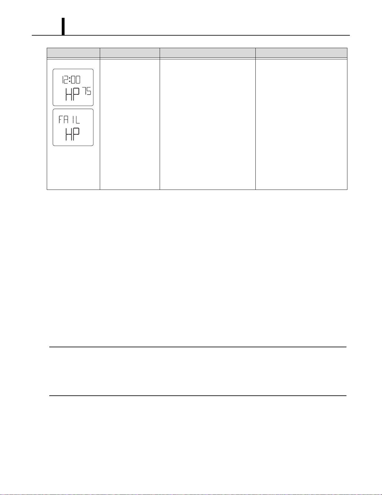
Activation of high
pressure switch
When high pressure switch
(connected to J104) activates
(=J104 input turns to open) 3 times
in 24 h, “HP” is indicated and signal
output (J106) turns on.
When it activates 10 times in 24 h,
“FAIL HP” is indicated and buzzer
sounds.
Find the cause of high pressure to
address it.
Check the following.
Ambient air temperature
65 °F (18.3 °C), 50 %RH
⇔95 °F (35 °C), 60 %RH
Air filter (if dirty, wash up.)
Condenser fan motor (if not
working, replace.) Defect of high
pressure switch (if switch is open
when unit is off, replace switch.)
Reset the system.
To RESET: Press ON/OFF and
HI/LO buttons on the control box
simultaneously for 5 sec.
LCD Display Description Condition Reset/Remedy
TU
AM
F
SET TEMP
HI
ON
COOL
FAN
Repair Section
33
Symptom
Possible Cause
Remedy
Checking Area Cause
Air volume
normal
Compressor
operates.
1.Usage conditions
(high temperature).
Operation near usage limits. Review the installation
place.
2.Dirt in condenser or
evaporator.
Insufficient heat exchange. Clean fins.
3.Frost in refrigeration cycle. Clogging at the frost section. Replace clogged section.
4.No temperature difference
between evaporator and
condenser.
Insufficient refrigerant. Check the leaking part,
then repair and charge
refrigerant.
Compressor
does not
operate.
1.Compressor coil resistance.
(0 ohm or ∞ ohm)
Short or open circuit. Replace compressor.
(In case of short, check
the compressor relay.)
2.Compressor relay. Open circuit or insufficient
contact.
Replace compressor
relay.
3.Compressor relay on the
relay board.
Open circuit or insufficient
contact.
Replace relay board.
4.Capacitor for compressor
motor.
Capacitor malfunction. Replace capacitor.
5.Voltage. Low voltage. Repair power.
Insufficient
air volume
No air.
1.Coil resistance of fan motor.
(0 ohm or ∞ ohm)
Short or open circuit. Replace fan motor.
2.Fan on-off relay on the relay
board.
Open circuit or insufficient
contact.
Replace relay board.
3.Fan HI/LO change relay on
the relay board.
Open circuit or insufficient
contact.
Replace relay board.
Insufficient
air volume.
1.Air filter. Clogged air filter. Clean air filter.
2.Evaporator. Clogged evaporator or
crushed fins.
Repair and clean fins or
replace it.
3.Duct connection state. Improper connection. Repair duct connection.
4.Fan motor. Insufficient rotation. Replace motor.
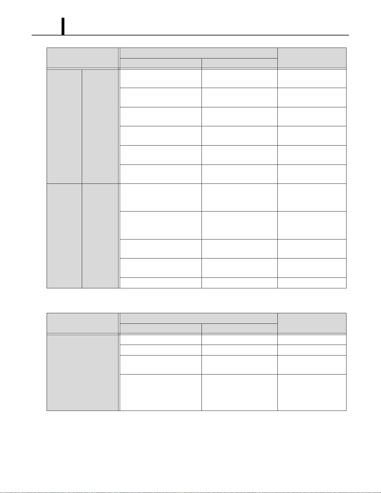
Repair Section
34
(2) Unit does not start (operate)
< NOTE >
•In this case, there is a possibility of safety device activating due to the clogged air filter. So make
sure to first clean the air filter and then start up again to confirm if the problem lies with the air filter.
•Check the installation site for operating temperature and installation space (unobstructed airflow).
Symptom
Possible Cause
Remedy
Checking Area Cause
Does not
operate at
all
Control
Panel
display turns
off.
1.Voltage. Power failure. Repair power.
2.Ground fault breaker trip. Ground fault or defective
ground fault breaker.
Repair ground fault section.
Reset or repair breaker.
3.LCDI power cord trip. LCDI power cord trip. Reset power cord.
Replace power cord.
4.Fuse. Fuse blown. Repair shorting section.
Replace fuse on the relay
board.
Repair Section
35
Control
panel
display
turns on
Control
Panel
display
shows error
codes.
1.Display code “FL”. Drain tanks are filled with
the drain water.
Discharge the drain water.
Improper drain switch
connection.
Check connection.
Defective drain switch. Replace drain switch.
2.Display code “AS”. Improper routing of drain
hose.
Repair drain hose, then reset
unit.
To RESET: Press ON/OFF
and HI/LO buttons on the
control box simultaneously
for 5 sec.
Defective condensate pump. Repair or replace
condensate pump, then reset
unit.
To RESET: Press ON/OFF
and HI/LO buttons on the
control box simultaneously
for 5 sec.
Missing jumper connector. Connect jumper connector.
3.Display code “RT”. Improper room thermistor
connection.
Check connection.
Defective room thermistor
(short or open).
Replace room thermistor.
4.Display code “FT”. Improper freeze protection
thermistor connection.
Check connection.
Defective freeze protection
thermistor (short or open).
Replace freeze protection
thermistor.
5.Display code “HP”. Improper high pressure
switch connection.
Check connection.
Defective high pressure
switch (short or open).
Replace high pressure
switch.
See “Stops after running a while” of Troubleshooting on
page 36.
6.Display code “ALRM”. Turn the input signal on and
continue it.
1)Check external input sig-
nal.
2) Reset the system.
To RESET: Press
ON/OFF and HI/LO but-
tons on the control box
simultaneously for 5 sec.
7.Display code “FZ”. See “Stops after running a while” of Troubleshooting on
page 36.
Symptom
Possible Cause
Remedy
Checking Area Cause
Repair Section
36
(3) Overflow of drain water
Symptom
Possible Cause
Remedy
Checking Area Cause
Stops
immediately
after
starting
Control
panel
display
normally.
1.Fan on-off relay on the relay
board.
Open circuit or insufficient
contact.
Replace relay board.
2.Fan HI/LO change relay on
the relay board.
Open circuit or insufficient
contact.
Replace relay board.
3.Fan motor insulation
resistance.
Insulation failure on fan
motor.
Replace fan motor.
4.Compressor relay. Open circuit or insufficient
contact.
Replace compressor
relay.
5.Compressor relay on the
relay board.
Open circuit or insufficient
contact.
Replace relay board.
6.Compressor insulation
resistance.
Insulation failure on
compressor.
Replace compressor.
Stops after
running a
while
Control
panel
display
normally.
1.Temperature of fan motor
(abnormally high).
Operation of safety device
(IOLF) due to fan motor
malfunction.
Replace fan motor.
2.Temperature of compressor
(abnormally high).
Operation of safety device
(IOLC) due to compressor
malfunction.
Replace compressor.
3.Refrigerant leakage. Insufficient refrigerant or gas
leakage.
Repair and charge
refrigerant.
4.Dirt on evaporator or
condenser.
Insufficient cooling of
evaporator or condenser.
Clean evaporator or
condenser.
5.Duct connection state. Improper connection. Repair duct connection.
Symptom
Possible Cause
Remedy
Checking Area Cause
Overflow from the unit.
1.Drain pan. Cracks in drain pan. Check and repair.
2.Water level in drain pan. Clogged drain hose. Check and replace.
3.Drain hole. Reversed air flow from drain
hole.
Insert a trap on discharge
drain hose.
4.Clogged air filter. Reversed air flow from drain
hole due to the excessive
negative pressure inside of
the unit.
Clean air filter.
Repair Section
37
(4) Abnormal noise or vibration
• To prevent abnormal noise or vibration, carefully determine the source of the problem and come
up with proper countermeasures to solve the problem so that it does not occur again.
7.4 Basic Inspection
• Perform the following inspection before disassembly.
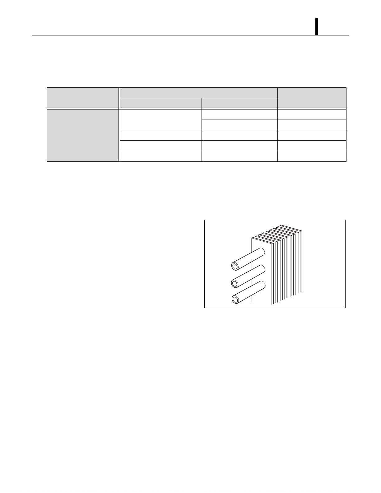
(1) Inspection of plate fins
• To inspect the plate fins of either the evaporator
or condenser, the air filter must be removed.
After removal of the air filters, inspect the plate
fins for any dirt, dust, lint, or debris that may
have caused insufficient cooling performance
of the unit. If cleaning of the fins is necessary, it
is recommended that this service be performed
by a qualified service technician.
(2) Examination of operating environment
• Operating environments can vary depending on location, climate and surrounding conditions.
Installation location also can cause operational problems. Consult your reseller concerning
operational environment requirements.
Symptom
Possible Cause
Remedy
Checking Area Cause
Abnormal noise or
vibration.
1.Fan. Fan interference. Repair interfering section.
Fan deformation. Replace fan.
2.Compressor fixing nuts. Looseness of nuts. Tighten nuts further.
3.Piping. Pipe interference. Repair interfering section.
4.Panel fixing screws. Looseness of screws. Tighten screws further.
I001780
Repair Section
38
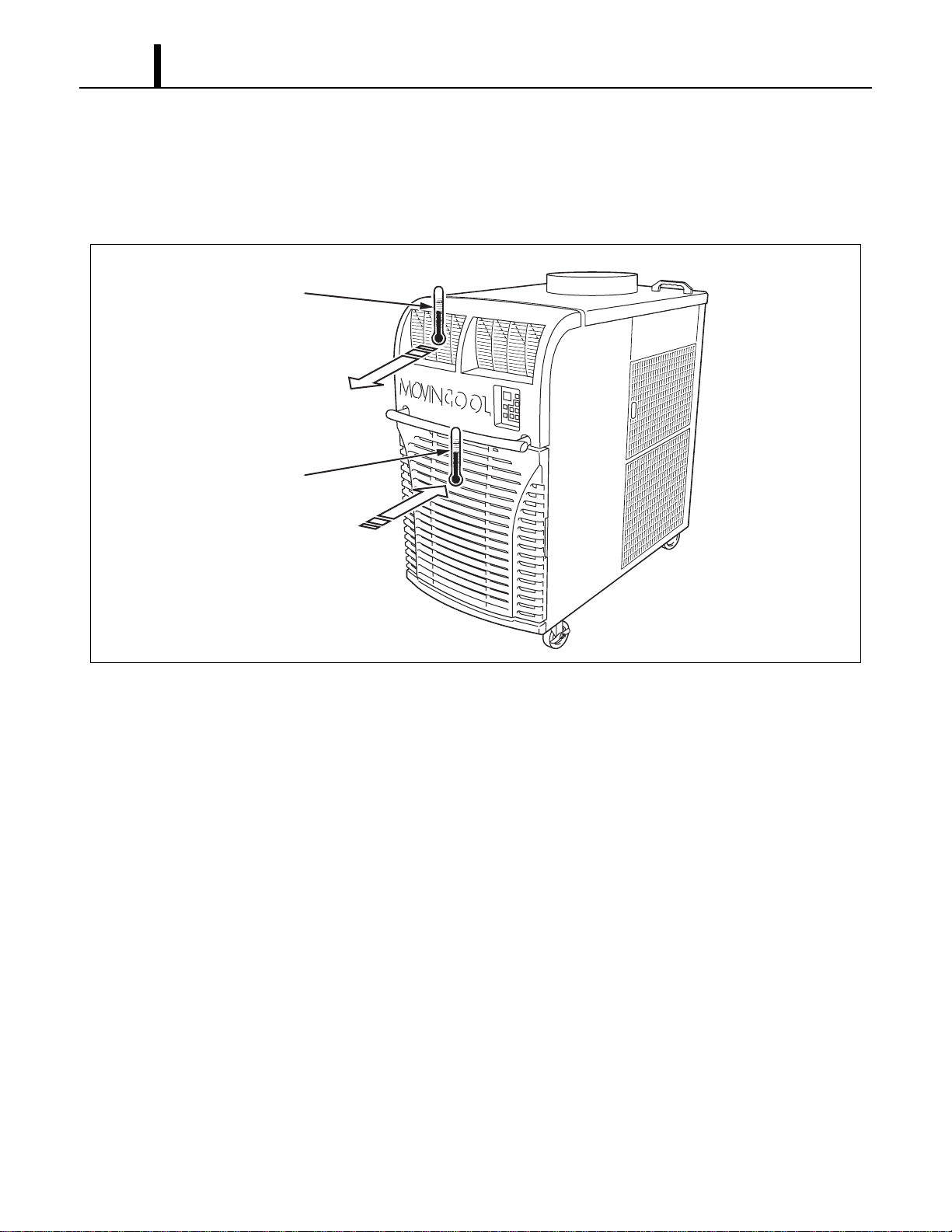
(3) Inspection of cooling capacity performance
• Measure the difference in temperature between the inlet of the evaporator and the cool air vent.
If the difference is out of the range given in the graphs on page 14 and 15, proceed with the
remedy suggested in the troubleshooting chart on page 32 to 37.
I001781
Thermometer
Thermometer
Cool Air Out
Evaporator Air In
Repair Section
39
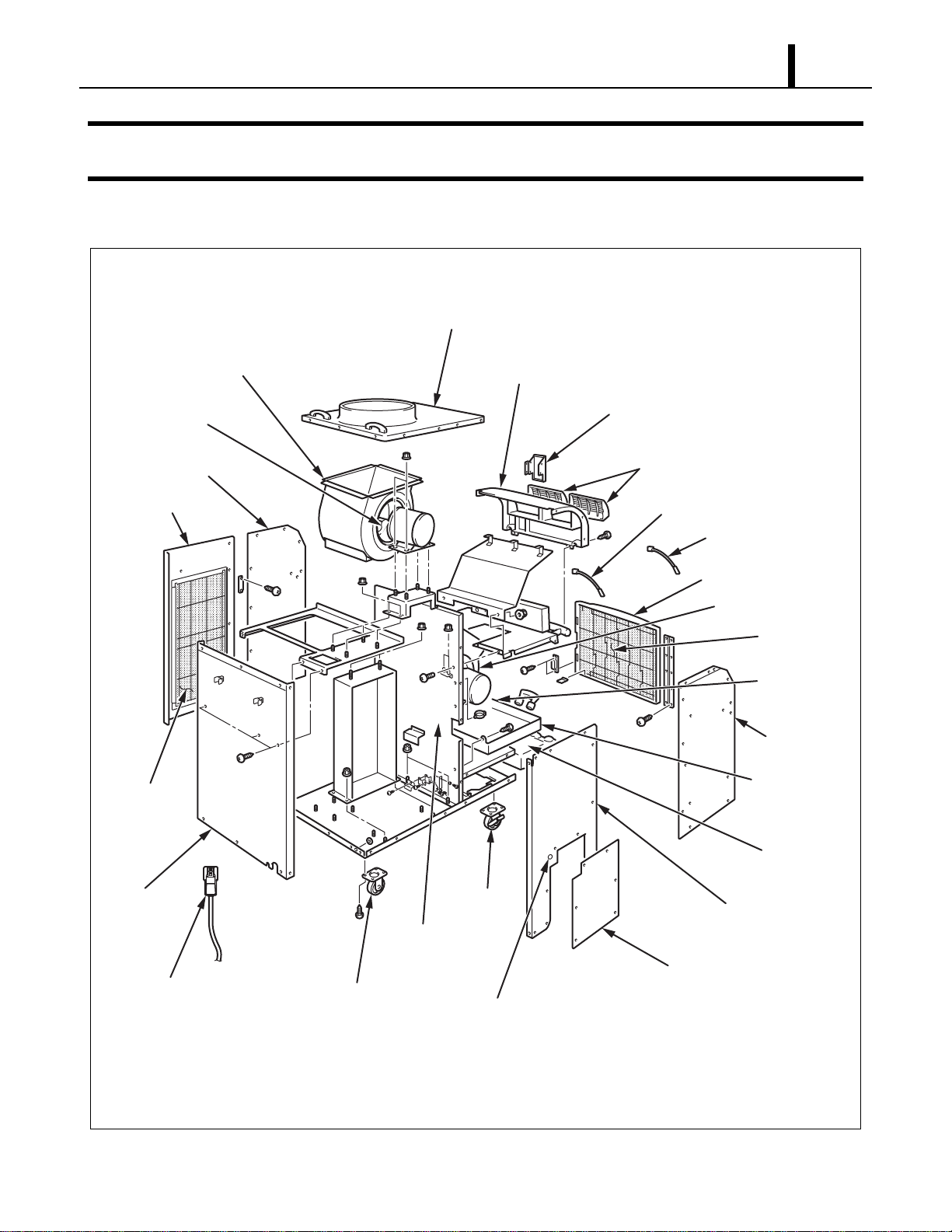
8. DISASSEMBLY
8.1 Parts Construction
I002272
Evaporator Fan
Condensate
Pump
(Optional)
Control Panel
Air Outlet Grill
Condenser Fan
Upper Panel
Rear Panel
Pivoting Caster
Power Cord
Pivoting
Caster
Drain Pan Assy
Drain Tanks
Front Left Panel
Front Right Panel
Room Thermistor
Freeze Protection Thermistor
Front Panel Filter Assy
Filter Element
Rear Left Panel
Rear Right Panel
Service Panel
Cap Cover
Middle Frame
Sub-Assy
Side Panel
Filter Assy
Blower housing
Upper Front Panel
Repair Section
40
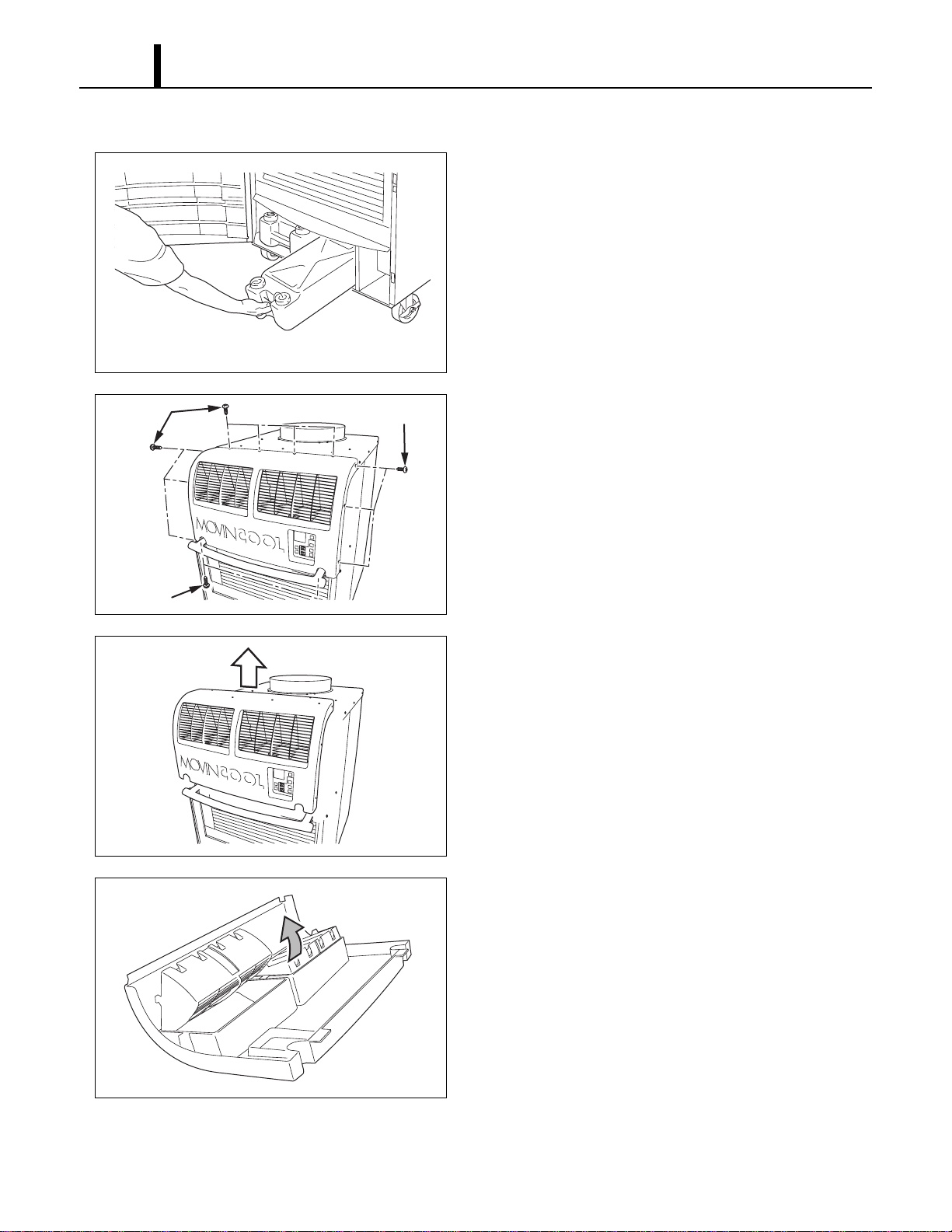
8.2 Disassembly
1) Remove drain tanks.
2) Remove twelve (12) screws from upper front
panel.
3) Slide upper front panel forward and remove.
4) Louver can be removed from upper front panel by
unsnapping the lock tap and removing the louver
from its pivots.
I001783
I001924
Screws (7)
Screws (3)
Screws (2)
I001925
I001786
Repair Section
41
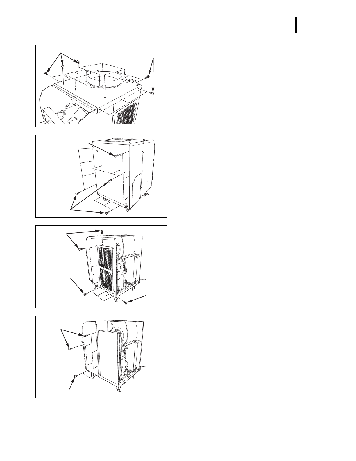
5) Remove twenty (20) screws from upper panel.
6) Remove thirteen (13) screws from rear panel.
7) Remove ten (10) screws from rear right panel.
8) Remove eight (8) screws from front right panel.
I002273
Screws (14)
Screws (6)
I002274
Screws (10)
Screws (3)
I002275
Screws (6)
Screws (3)
Screw (1)
I002276
Screws (6)
Screws (2)
Repair Section
42
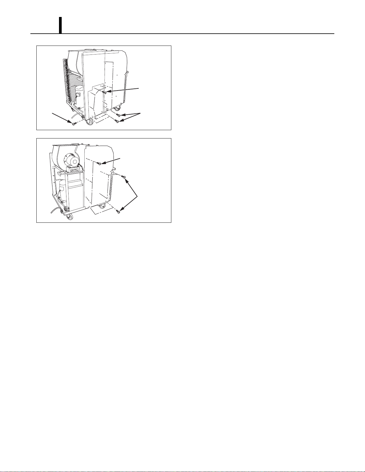
9) Remove seven (7) screws from service panel
and six (6) screws from rear left panel.
10) Remove eight (8) screws from front left panel.
I002278
Screw (1)
Screws (5)
Screws (7)
I002279
Screws (3)
Screws (5)
Repair Section
43
8.3 Removal of Electrical Parts
(1) Control box
1) Remove seven (7) screws from service panel. (See page 42.)
2) Remove electrical parts.
- Relay: Remove two (2) screws from control box.
- Terminal block: Remove four (4) screws from control box.
- Terminal block (signal connection): Remove two (2) screws from control box.
- Capacitor: Remove two (2) screws from control box.
I001771
Terminal Block
(Signal Connections)
Relay Board Fuse
Relay Board
<Control Box>
Relay
Terminal Block
Dip Switch
Fan Capacitor
(Condenser)
Fan Capacitor
(Evaporator)
Compressor
Capacitor
TB2
TB1
Repair Section
44
(2) Relay board
1) Remove seven (7) screws from service panel. (See page 42.)
2) Disconnect ten (10) connectors, and remove five (5) screws from relay board.
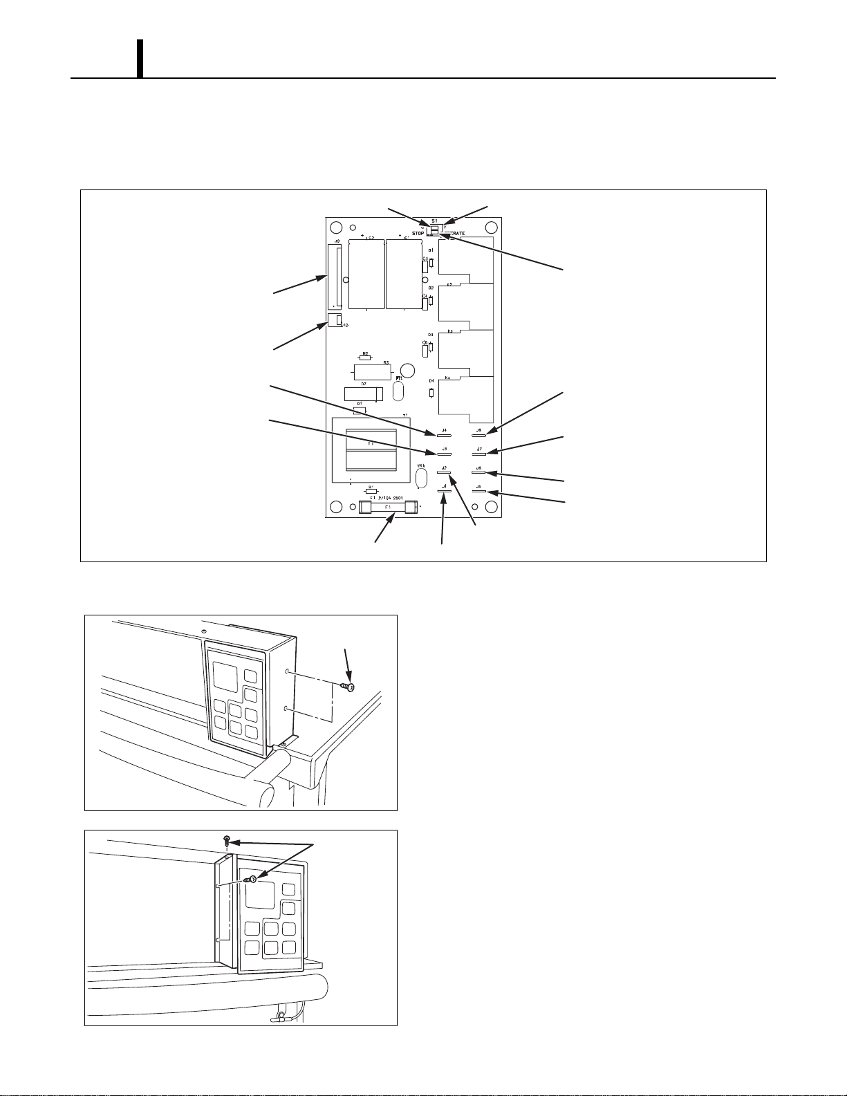
(3) Control board
1) Remove two (2) screws from the control panel
stay.
2) Remove three (3) screws from the control panel
stay.
I001793
Temperature Scale Display Switch
Dip Switch
Fan Mode Control Switch
To Control Board (10 pin)
To Condensate Pump (2 pin)
To Evap. Fan Motor (HI)
To Evap. Fan Motor (LO)
To Cond. Fan Motor (HI)
To Cond. Fan Motor (LO)
To Comp. Driver Relay
To Comp. Relay
Power (#R1) On Terminal Block
Power (#T1) On Terminal Block
Relay Board Fuse
I002179
Screws (2)
I002180
Screws (3)
Repair Section
45
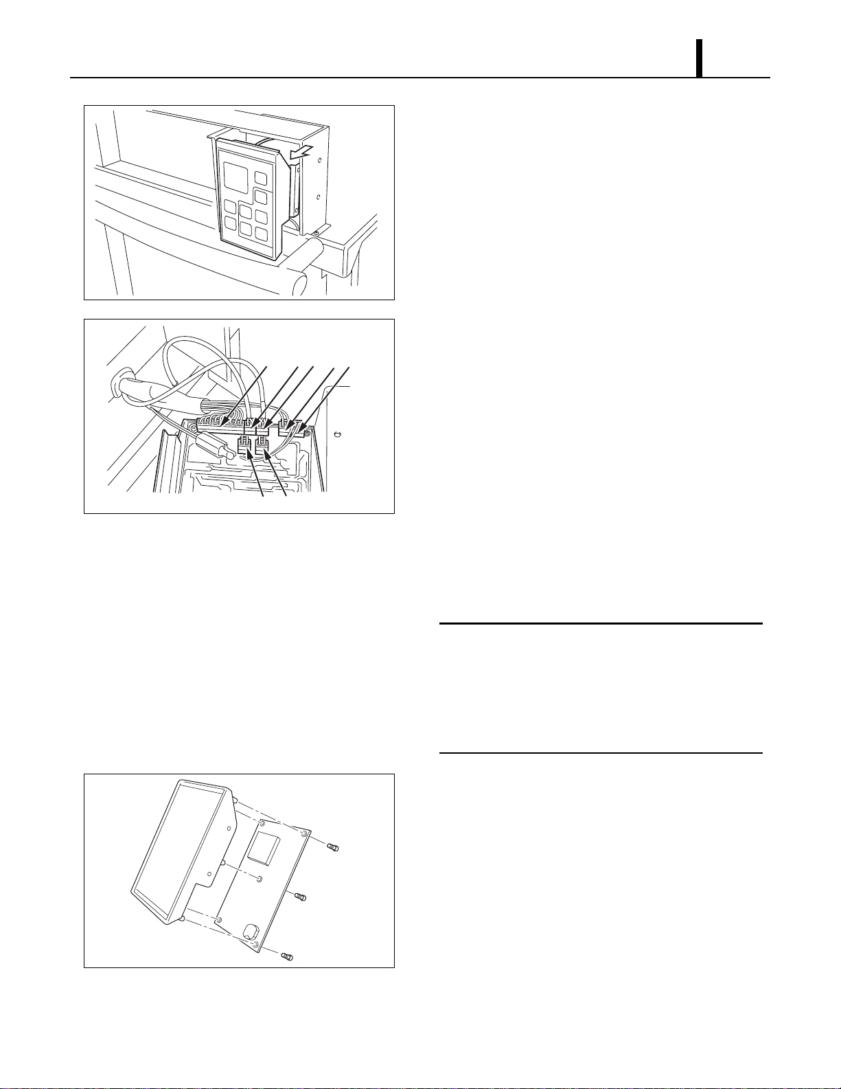
3) Slowly slide control panel assembly out of box.
4) Disconnect the following connectors from the
control board:
(A) J201 (10-pin) Wire Harness, Relay Board to
Control
(B) J101 (2-pin) Room Temperature Thermistor
(C) J102 (2-pin with black tape) Freeze
Protection Thermistor
(D) J103 (2-pin) Drain Tank Switch
(E) J104 (2-pin) High Pressure Switch
(F) J106 (2-pin) Output signal terminal
(G) J108 (2-pin) Input signal terminal
< NOTE >
Mark each of the 2-pin connectors with a
different color marker to ensure the correct
orientation when they are reconnected or label
all wire sets with tape. Numbering the wire sets
from (A) through (G).
5) Remove the five (5) screws from the control
board on the control panel assembly. Remove
the control board.
I002181
I002182
A
B
C
E
F
G
D
I001804
Repair Section
46
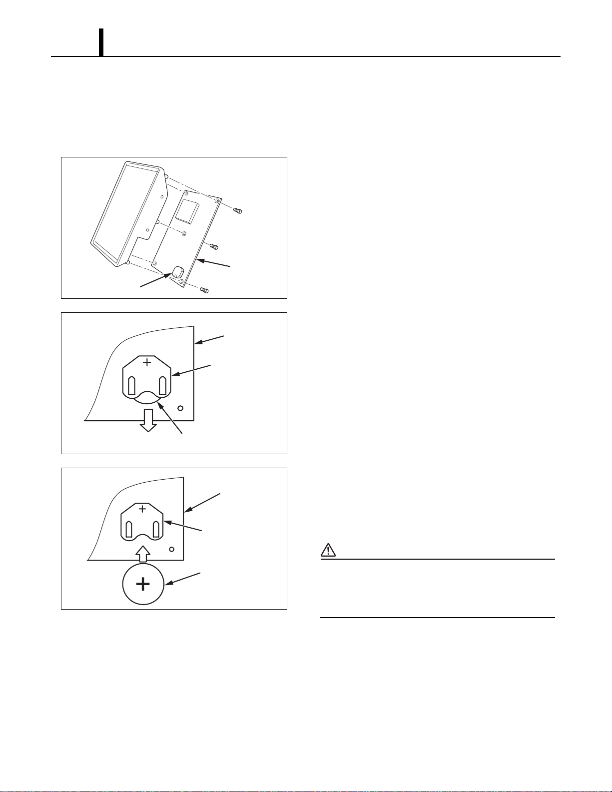
(4) Battery replacement of control board
• When the power is unplugged from the unit, and control board is automatically resetting clock
and program, it is time to change the battery on the control board to avoid resetting of clock and
program.
1) Disassemble control board. (See page 44 and
45.)
2) See diagram for battery removal.
3) Insert new battery securely in the direction shown
in the drawing.
Specifications:
- Type: 3 V CR2450 or equivalent
CAUTION
When inserting the battery, make sure the
direction of polarity (plus/minus) is correct (as
shown).
I001805
Control
Board
Battery
I001806
Battery (Old)
Holder
Control Board
I001807
Holder
Battery (New)
Control Board
Repair Section
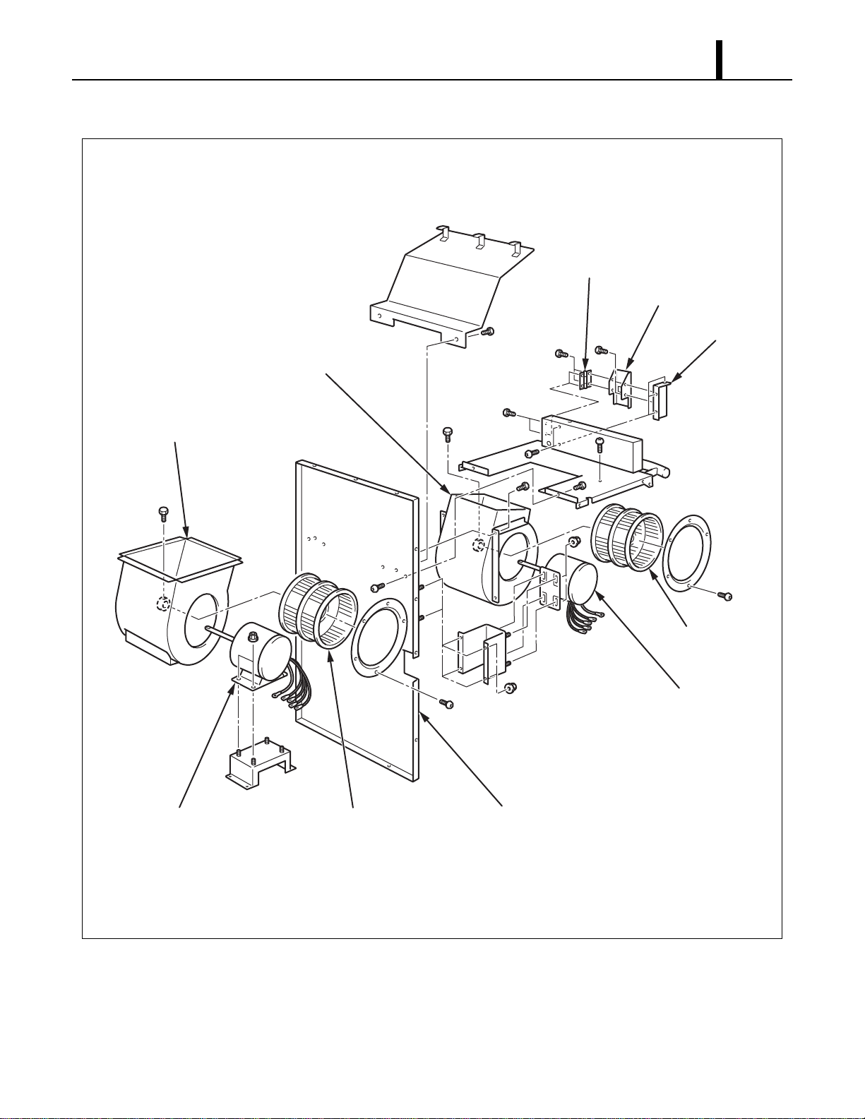
47
8.4 Removal of Blower Assembly
I001795
Evaporator
Fan Motor
Condenser
Fan Motor
Condenser Fan
Casing
Evaporator Fan
Casing
Condenser Fan
Evaporator Fan
Center Panel
Control Panel Stay
Control Panel Stay
Control Panel
Repair Section
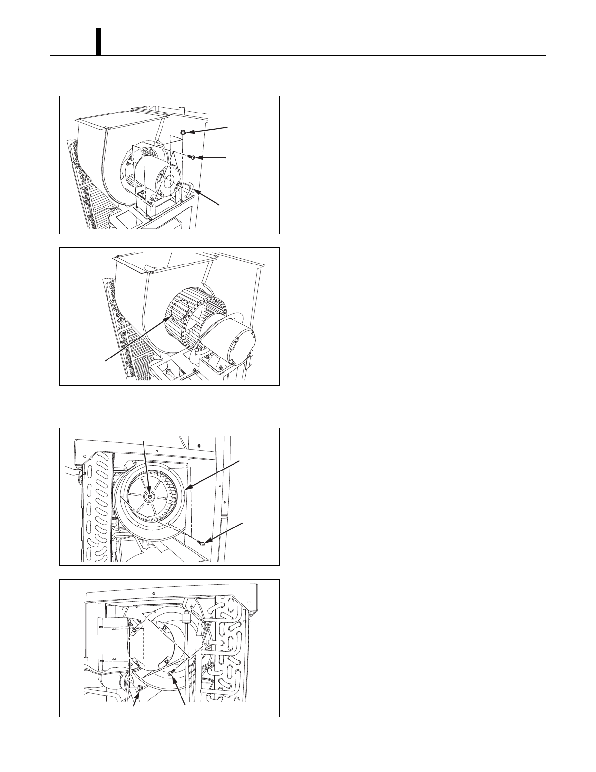
48
(1) Removal of condenser fan and fan motor
1) Remove four (4) nuts and three (3) screws in the
location shown. Then remove fan motor wire.
2) Loosen the set screw using a hex key. Then
remove the fan and fan motor.
(2) Removal of evaporator fan and fan motor
1) Loosen the set screw using a hex key. Then
remove three (3) screws on the ring. Then
remove this ring and evaporator fan.
2) Remove evaporator fan motor wire, three (3)
screws on the ring and four (4) nuts from housing
while holding fan securely with one hand. Then
remove evaporator fan motor.
I002280
Nuts (4)
Screws (3)
Fan Motor Wire
I001797
Set Screw
I002281
Set Screw
Screws (3)
Ring
I002282
Screws (3)Nuts (4)
Repair Section
49
8.5 Inspection of Capacitor (for Fan Motor and Compressor)
(1) Ohmmeter method
• Set the ohm-meter to the 10M range. Place the
two probes against the two terminals of the
capacitor. At first, the ohm-meter should
indicate small value, then the reading should
gradually increase towards infinity. This
indicates that the capacitor is charging. If the
reading indicates infinity right away (open) or
the ohm-meter fails to move from 0. (shorted),
replace the capacitor.
(2) Capacitance tester method
• Using a capacitance tester and the chart on page 21, test the capacitor for the value indicated.
If the value tested is not within 10 % of indicated capacitance, replace the capacitor.
WARNING
• Properly discharge the capacitor(s) before testing and after testing has been completed.
• Failure to do so could cause damage to test equipment or the unit and/or result in
personal injury (electrical shock) or death.
8.6 Inspection of Drain Switch
• Check for continuity between terminals 1 and 2
when drain switch is pressed. With drain switch
depressed, there is no continuity between
terminals 1 and 2. Replace drain switch if
continuity does not satisfy the above condition.
I001808
I001809
2
NC
C
1
DS2
DS1
To J103
Drain Switch
Top of Base Plate
Repair Section
50
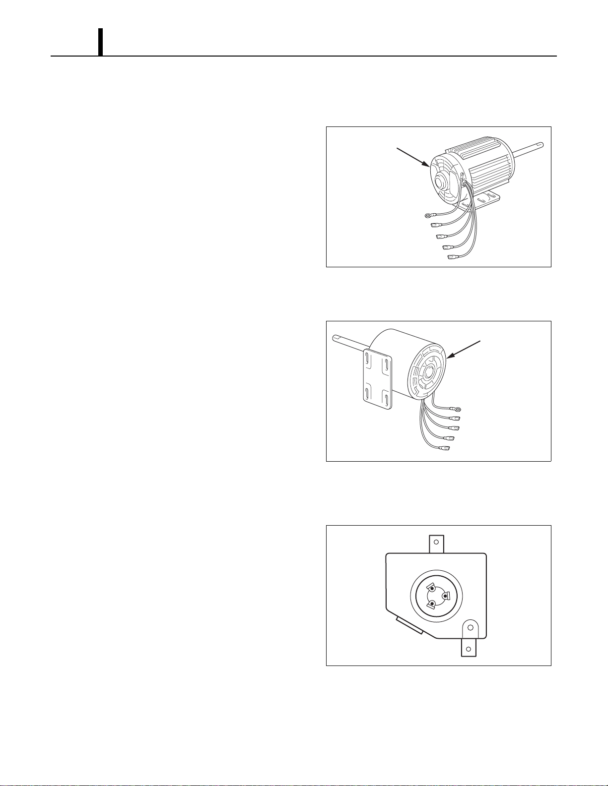
8.7 Inspection of Fan Motor
(1) Condenser fan motor
• Measure resistance across the terminals of the
fan motor. (All terminals must be disconnected
from the unit.)
• Between terminals (at 77 °F (25 °C))
- J6-CF11 Approx. 12.1 ohm
- J6-CF12 Approx. 12.1 ohm
- CF11-CF12 Approx. 24.1 ohm
• If the measured resistance is not equal to these
standard values, replace the fan motor.
(2) Evaporator fan motor
• Measure resistance across the terminals of the
fan motor. (All terminals must be disconnected
from the unit.)
• Between terminals (at 77 °F (25 °C))
- J8-CF21 Approx. 19.7 ohm
- J8-CF22 Approx. 48.5 ohm
- CF21-CF22 Approx. 68.0 ohm
• If the measured resistance is not equal to these
standard values, replace the fan motor.
8.8 Inspection of Compressor Motor
• Measure resistance across the terminals of the
compressor motor. (All terminals must be
disconnected from the unit.)
• Between terminals (at 77 °F (25 °C))
- R-C Approx. 0.4 ohm
- C-S Approx. 0.6 ohm
- S-R Approx. 0.9 ohm
• If the measured resistance is not equal to these
standard values, replace the compressor. The
overload relay is internal to the compressor.
I001775
Condenser Fan Motor
Ground (Green/Yellow)
J5 Low (Red)
CF12 (Brown/White)
CF11 (White or Orange)
J6 High (Black)
I001774
Evaporator Fan Motor
Ground (Green/Yellow)
J7 Low (Red)
CF22 (Brown/White)
CF21 (White)
J8 High (Black)
I001810
C
S
R
T1
T2
T3

Repair Section
51
8.9 Inspection of Wiring Connection
• Refer to the Wiring Diagrams on page 19 and check for connection of each wire.
8.10 Inspection of Thermistor
• Using an Ohm-meter, check the resistance value across the 2-pin connector. At normal
temperature (77 °F (25 °C)) either thermistor (room or freeze) should measure approximately
10K ohm.
8.11 Inspection
• In most cases, the probable cause for insufficient cooling is a clogged system, leakage or an
incorrect amount of refrigerant. In such cases, inspect the system according to the following
procedure.
(1) Inspection of clogged system
• Check the component parts of the refrigerant system, including piping, that could be clogged
with refrigerant. If clogged with refrigerant, only the clogged part is frosted partially. In such a
case, change the part in question.
(2) Inspection of refrigerant leak
• Carefully check all connections, and each component for leaks whenever the refrigerant system
is installed or repaired. Use an electronic gas leak tester to inspect the system.
(3) Insufficient refrigerant
• In case the unit is judged to be deficient in cooling capacity, make sure to perform the inspections
in page 52. 9.1 (1) and page 52. 9.1 (2) to confirm the cause of trouble. Then, charge the system
with refrigerant to the specified amount.

Repair Section
52
9. REFRIGERANT SYSTEM REPAIR
9.1 Repair of Refrigerant System
• In case there is a leak, obstruction, or trouble in the refrigerant system of the Office Pro 36,
replace or repair the part in question. After replacing any component all connections must be
brazed.
(1) Proper brazing techniques
• It is desirable to use a slightly reducing flame. Oxyacetylene is commonly used since it is easy
to judge and adjust the condition of the flame. Unlike gas welding, a secondary flame is used for
brazing. It is necessary to preheat the base metal properly depending on the shape, size or
thermal conductivity of the brazed fitting.
• The most important point in flame brazing is to bring the whole brazed fitting to a proper brazing
temperature. Care should be taken to not cause overflow of brazing filler metal, oxidization of
brazing filler metal, or deterioration due to the overheating of flux.
(2) Brazed fittings and fitting clearance
• In general, the strength of brazing filler metal is
lower than that of the base metal. So, the
shape and clearance of the brazed fitting are
quite important. As for the shape of the brazed
fitting, it is necessary to maximize its adhesive
area. The clearance of the brazed fitting must
be minimized to facilitate brazing filler metal to
flow into it by capillary action.
(3) Cleaning brazing filler metal and pipe
• When the refrigerant system has been opened up, exposure to heat may have caused brazing
filler metal to stick to the inside and outside of the pipe. Brazing filler metal may also be
compounded with oxygen in the air to form oxide film. Fats and oils may stick to the pipe from
handling. All these factors can reduce effectiveness of brazing. It is necessary to eliminate
excess brazing filler metal using sand paper and by cleaning thoroughly with a solvent such as
trichlene.
CAUTION
Do not use chlorine cleaner.
I002225
Clearance
Clearance From The Pipe Fitting and Tubing.
0.001~0.003 in
(0.025~0.075 mm)
a
a
Repair Section
53
(4) Use of dry nitrogen gas
• During brazing, the inside of the pipe undergoes an oxidative reaction due to the brazing flame.
Introduce dry nitrogen gas (0.27 gal (1 L/min); adjust with the flow regulator) through the pinch-
off tube of the refrigerant.
< NOTE >
Take care not to allow dirt, water, oil, etc. to enter into the pipe.
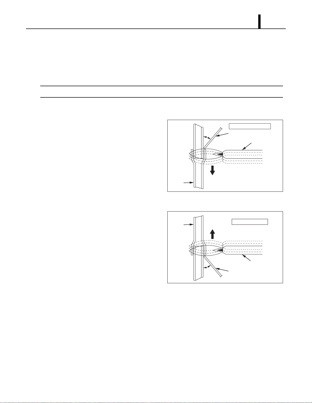
(5) Vertical Joint
• Heat the whole brazed fitting to a proper
brazing temperature. Bring the brazing filler
metal into contact with the fitting so that the
brazing filler metal starts flowing by itself.
• Stop heating the fitting as soon as the brazing
filler metal has flown into the clearance. Since
the brazing filler metal flows easily into the
portion heated to a proper temperature, it is
essential to keep the whole fitting at a proper
brazing temperature.
I000564
Burner
45°
Tube
Brazing Filler Metal
Vertical Down Joint
I001725
Burner
45°
Tube
Brazing Filler Metal
Vertical Up Joint
Repair Section
54
9.2 Removal of Refrigeration Cycle Components
CAUTION
•Before any refrigeration cycle component can be replaced, it is necessary to recover the
refrigerant using standard recovery procedures and equipment.
•To prevent oxidation, dry nitrogen should be conducted (flow rate 0.27 gal (1 L/min)) through the
pinch-off tube during any brazing operation.
•During any component replacement involving brazing, shield nearby parts with a steel plate, etc.,
to protect them from the flame.
•Evaporator
• Capillary tube
• Condenser
• Compressor
• High Pressure Switch
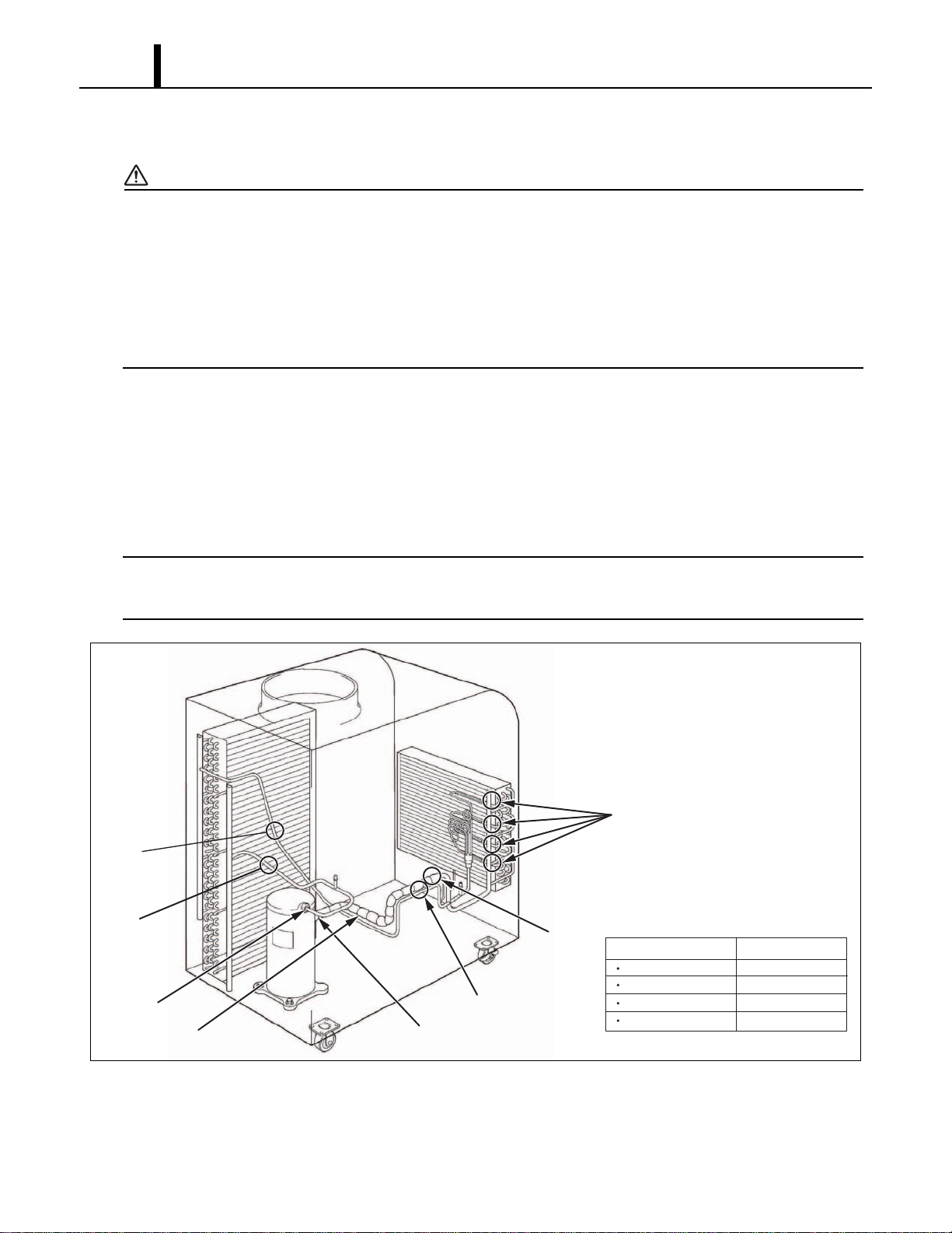
< NOTE >
When replacement of the compressor, attach the two pipes (Pipe 1, Pipe 2) which are packaged
in Compressor Assy as following figure.
I001811
Compressor
A & F
A & B
C & D
C & E
Condenser
Capillary Tube
Evaporator
Part to Replace Disconnect At
A
B
Pipe 1
Pipe 2
C
E
D
F
Repair Section
55
9.3 Charging the System with R-410A Refrigerant
• Always ensure that the refrigerant system has been properly evacuated before charging with the
specified amount of R-410A.
• Equipments is only for R-410A.
• Liquid charge (no gas charge).
• Make sure not to use more than 90 % of the initial weight of R-410A in the cylinder.
WARNING
• When handling refrigerant (R-410A), the following precautions should always be
observed:
- Always wear proper eye protection while handling refrigerant.
- Maintain the temperature of the refrigerant container below 104 °F (40 °C).
- Perform repairs in a properly ventilated area. (Never in an enclosed environment.)
- Do not expose refrigerant to an open flame.
- Never smoke while performing repairs, especially when handling refrigerant.
- Be careful the liquid refrigerant does not come in contact with the skin.
• If liquid refrigerant strikes eye or skin:
- Do not rub the eye or the skin.
- Splash large quantities of cool water on the eye or the skin.
- Apply clean petroleum jelly to the skin.
- Go immediately to a physician or to a hospital for professional treatment.
I002226
Step 1
Step 5
Step 6
Step 4
Step 3
Step 2
Connect manifold gauge.
1) Evacuate the system.
• 15 min or more.
• 30 inHg (100 kPa) or more of vacuum.
2) Stop evacuating the system.
• Leave for 5 min.
3) Check the vacuum.
When leak is found,
repair the connection
or components.
Charge the system with R-410A.
• See specifications on page 12.
Remove manifold gauge.
Test the system for leaks.
Connect to refrigerant source.
Repair Section
56
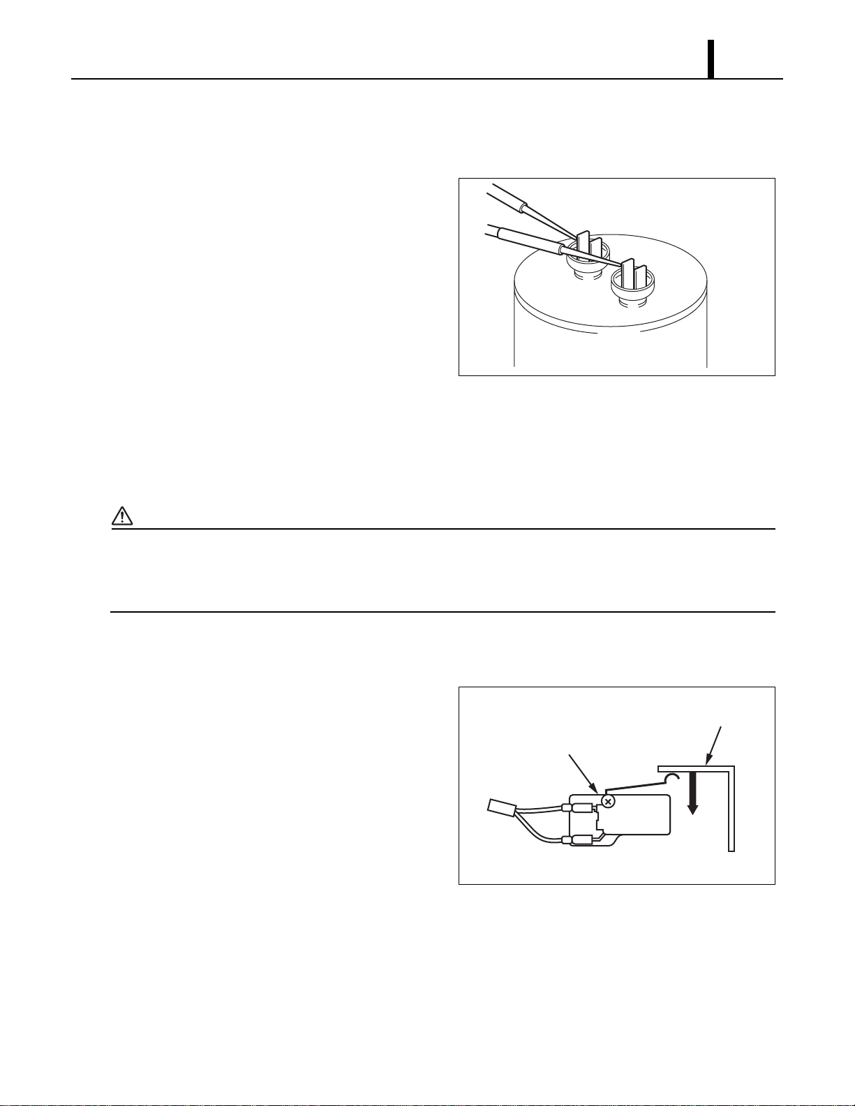
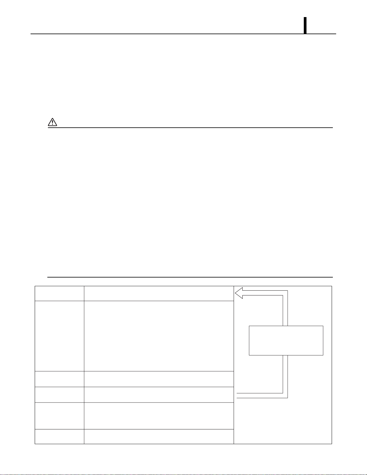
(1) Connection of gauge manifold
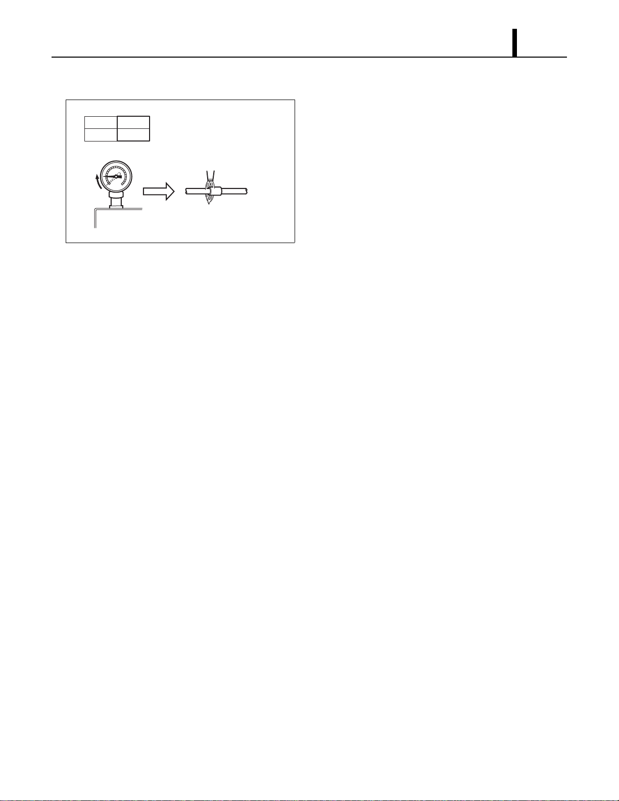
1) Properly remove the crushed end of the pinch-off
tube at the high pressure side and the low
pressure side of the refrigerant cycle with a pipe
cutter.
2) Fit the process tube fitting to the pinch-off tube on
both sides.
3) Connect the charging hoses (red-high pressure
side) for the gauge manifold to the process tube
fitting.
< NOTE >
Connect the hoses using care not to mistake
the high pressure side for the low pressure side
and vice versa.
4) Connect the charging hose (green) at the center
of the gauge manifold to the vacuum pump.
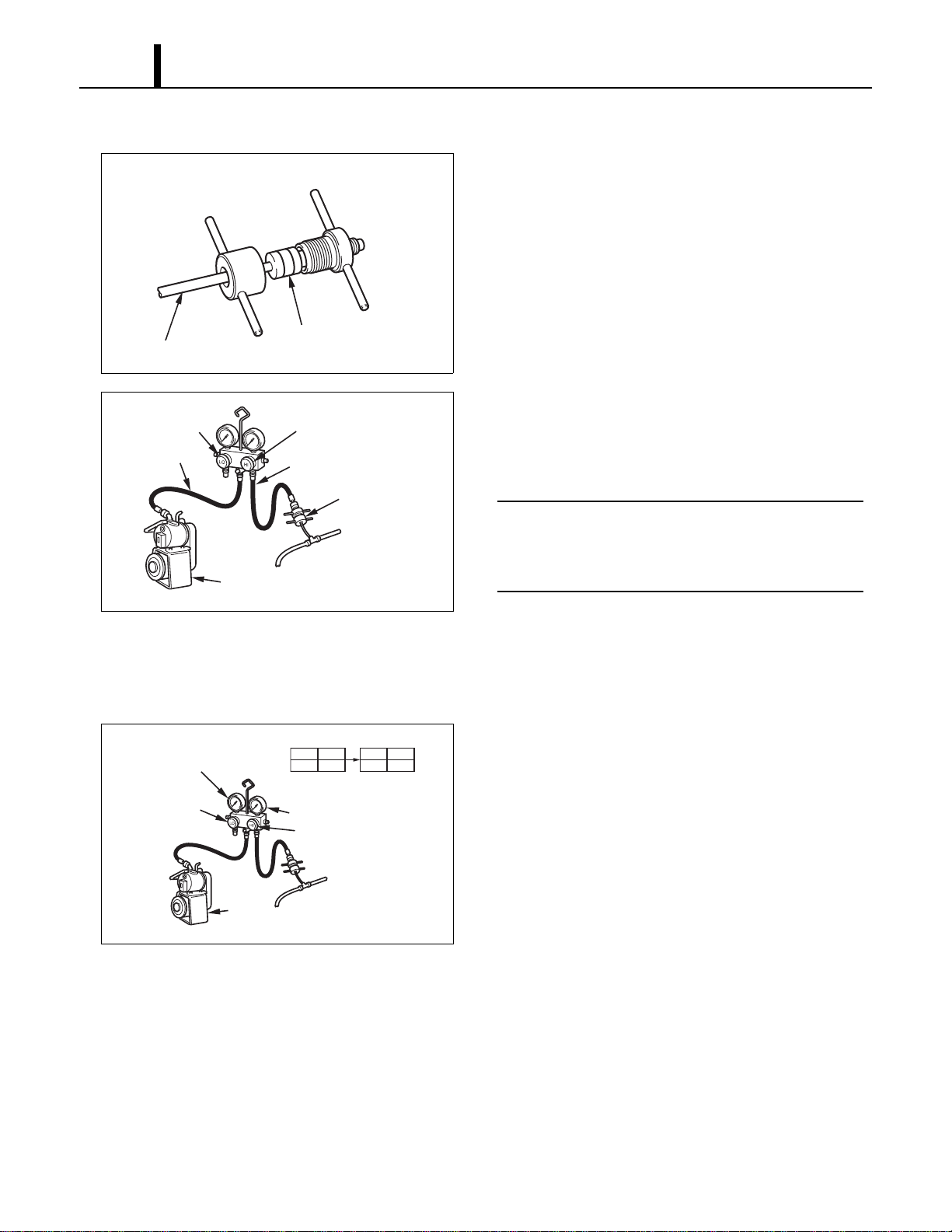
(2) Evacuation
1) Open the high pressure valve (Hl) of the gauge
manifold.
2) Turn on the vacuum pump to start evacuation.
(Evacuate the system for approximately 15 min.)
3) When the low pressure gauge indicates 30 inHg
(100 kPa) or larger, turn off the vacuum pump
and close the high pressure valves of the gauge
manifold.
I002183
Pinch-Off Tube
Seal
Charging Hose
Side
Refrigerant
Cycle Side
I000568
High Pressure Valve
(Closed)
High Pressure
Side Tube
Vacuum Pump
(when stopped)
Low Pressure
Valve (Closed)
Red Hose
Green Hose
Process Tube Fitting
I002227
LO
Closed
HI
Open
LO
Closed
HI
Closed
Valve Setting
30 inHg (100 kPa) or larger
High Pressure Valve
High Pressure Gauge
Gauge
High Pressure
Side Tube
Vacuum Pump
(in Operation)
Low Pressure
Valve
Repair Section
57
(3) Checking vacuum
1) Leave the high pressure valve and the low
pressure valve of the gauge manifold closed for
five minutes or more, and confirm that the gauge
pointer does not return to zero.
2) If the gauge pointer returns gradually to zero
there is a leak somewhere in the system (this
could also include gauge manifold). Perform leak
check according to procedure indicated in the
next step. Once leak has been found and
repaired evacuate the system once more, and
confirm system holds vacuum.
I002184
Return
Pipe Brazing
Leave valves closed for 5
min or more. Pointer of
pressure gauge returning to
zero indicates there is a leak.
LO
Closed
HI
Closed
Valve Setting
Pressure Gauge
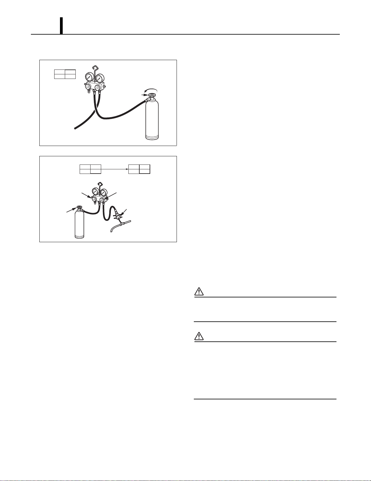
Repair Section
58
(4) Checking gas leak
1) Remove the charging hose (green) from the
vacuum pump, and connect the hose to the
refrigerant cylinder (R-410A).
2) Loosen the nut on the gauge manifold side of the
charging hose (green).
3) Open the valve of refrigerant cylinder perform air
purging in the charging hose (green). Then
tighten the nut.
4) Open the high pressure valve of the gauge
manifold. Charge the system with refrigerant until
the low pressure gauge indicates 57 psi
(390 kPa). After charging is complete, close the
high pressure valve.
5) Open the valve of refrigerant cylinder perform air
purging in the charging hose (green). Then
tighten the nut.
6) Check carefully for gas leaks inside the
refrigerant system using the gas leak tester.
7) Repair any leak.
WARNING
Do not attempt any repair on a charged
system.
WARNING
Before checking for gas leaks, fully confirm
that there is nothing flammable in the area
to cause an explosion or fire. Contact of
refrigerant with an open fire generates
toxic gas.
I001901
Open The Valve
of Refrigerant
Cylinder
To Process Tube Fitting
Charging Hose
(Green)
Refrigerant
Cylinder R-410A
Red
LO
Closed
HI
Closed
Valve Setting
Air Purging
I002228
LO
Closed
HI
Open
LO
Closed
HI
Closed
Refrigerant
Cylinder R-410A
Valve Setting
Gauge Reading
57 psi
(390 kPa)
Open High Pressure
Valve
High Pressure
Side Tube
Low Pressure
Valve (Closed)
Process Tube Fitting
Refrigerant
Cylinder
Valve
(Open)
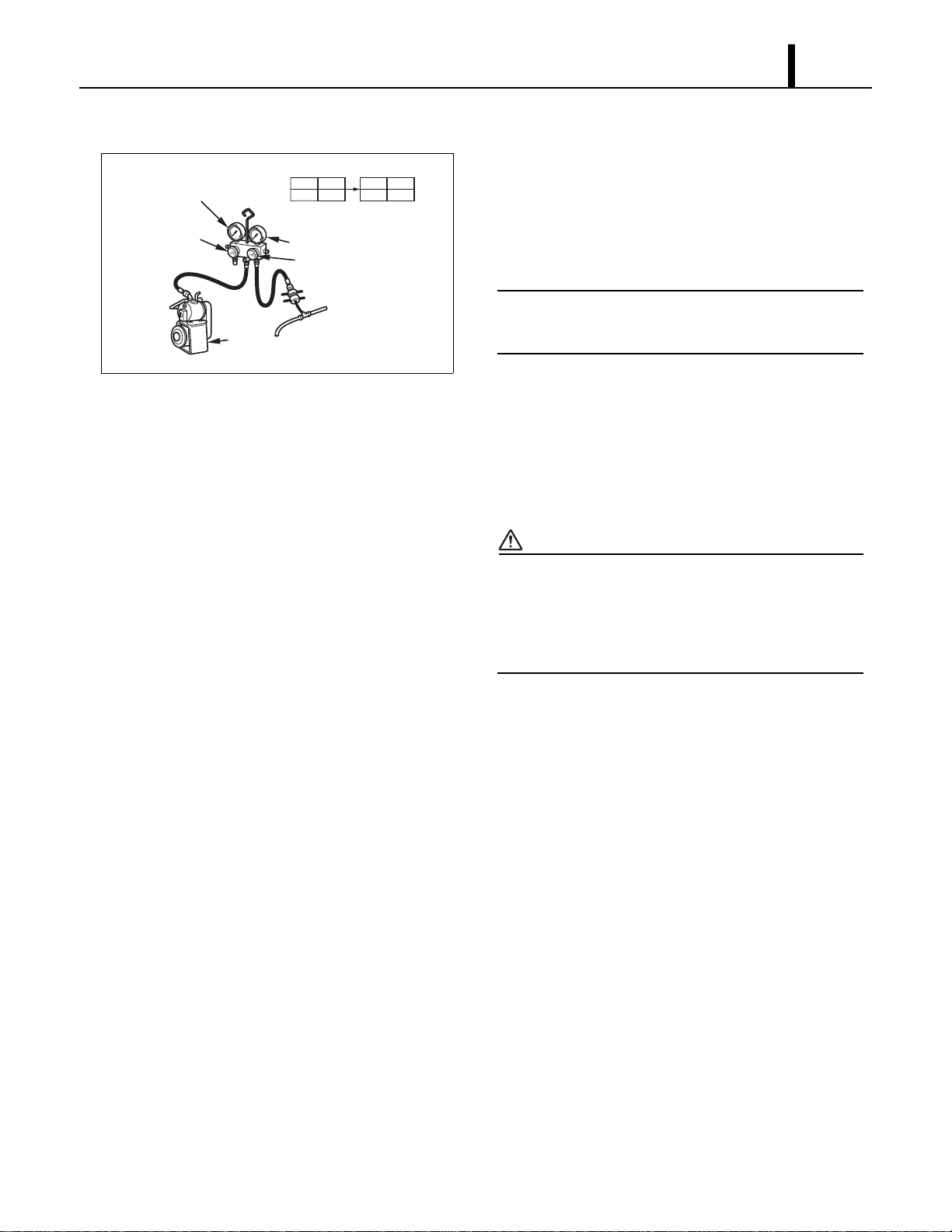
Repair Section
59
(5) Evacuation (repeat)
1) Close the valve of the refrigerant cylinder. Then
remove the charging hose (green) from the
refrigerant cylinder, and connect it to the
refrigerant recovery machine.
< NOTE >
Keep the high pressure valve and the low
pressure valve of the gauge manifold closed.
2) Using procedure in the “Evacuation”, evacuate
the system until the low pressure gauge indicates
30 inHg (100 kPa) or larger. (For 15 min or more.)
3) After evacuation is complete, close the high and
the low pressure valves of the gauge manifold.
CAUTION
Make sure to evacuate the system twice or
more using the repetitive vacuum method.
Evacuate the system an additional time on
rainy or humid days.
I002227
LO
Closed
HI
Open
LO
Closed
HI
Closed
Valve Setting
30 inHg (100 kPa) or larger
High Pressure Valve
High Pressure Gauge
Gauge
High Pressure
Side Tube
Vacuum Pump
(in Operation)
Low Pressure
Valve
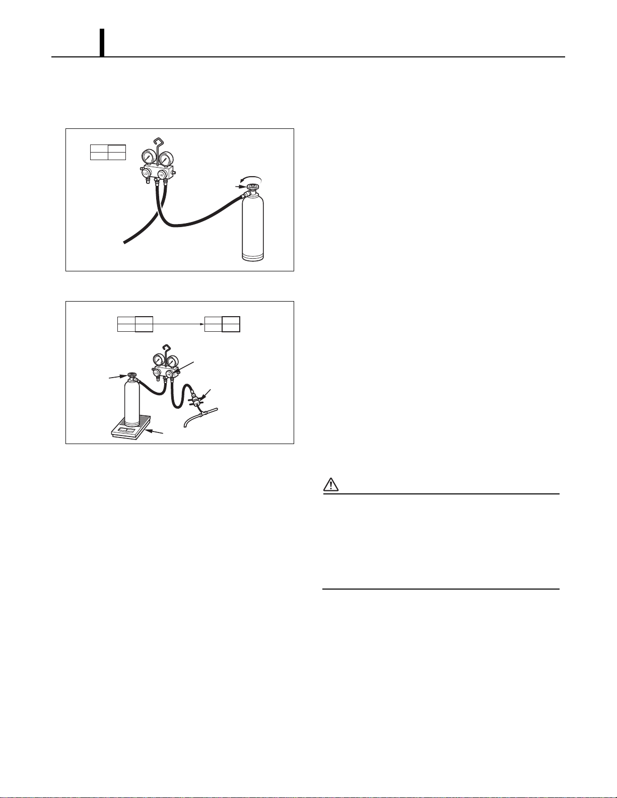
Repair Section
60
9.4 Refrigerant Charging Work
(1) Refrigerant charging
1) Remove the charging hose (green) from the
vacuum pump, and connect it to the refrigerant
cylinder
(R-410A).
2) Loosen the nut on the gauge manifold side of the
charging hose (green). Open the valve of the
charging hose (green). Open the valve of the
refrigerant cylinder. After air purging, tighten this
nut and close the valve of the refrigerant cylinder.
3) Securely place the refrigerant cylinder on a scale
with a weighing capacity of 70 lb (30 kg) that is
graduated by 0.2 oz (5 g).
4) Open the high pressure valve of the gauge
manifold and the valve of the refrigerant cylinder.
Charge the system with refrigerant to the
specified amount.
Standard Amount of Refrigerant: 2.38 lb
(1080 g)
CAUTION
The amount of refrigerant charged has a great
effect on the cooling capacity of the unit.
Charge to the specified amount, always
observing the scale graduations while
charging.
5) Close the high pressure valve of the gauge
manifold and the valve of the refrigerant cylinder.
I001901
Open The Valve
of Refrigerant
Cylinder
To Process Tube Fitting
Charging Hose
(Green)
Refrigerant
Cylinder R-410A
Red
LO
Closed
HI
Closed
Valve Setting
Air Purging
I001903
LO
Closed
HI
Open
LO
Closed
HI
Closed
Refrigerant
Cylinder R-410A
Valve Setting
Specified Amount
of Refrigerant
High Pressure Valve
High Pressure
Side Tube
Process Tube Fitting
Valve of
Refrigerant
Cylinder
Weight
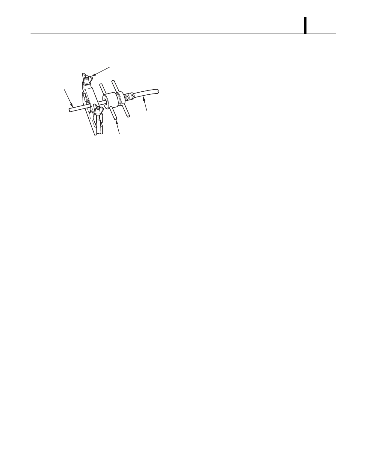
Repair Section
61
(2) Removal of gauge manifold
1) Crimp the pinch-off tube with a pinch-off tool.
2) Remove the gauge manifold and the process
tube fitting. Crush the end of the pinch-off tube.
3) Braze the end of the pinch-off tube.
4) Ensure that a gas leak is not present at the
pinched off portion and the brazed end.
I002185
Pinch-Off Tube
Pinch-Off Tool
Process Tube Fitting
Charging Hose
To Gauge
Manifold Side
To Refrigerant
Cycle Side
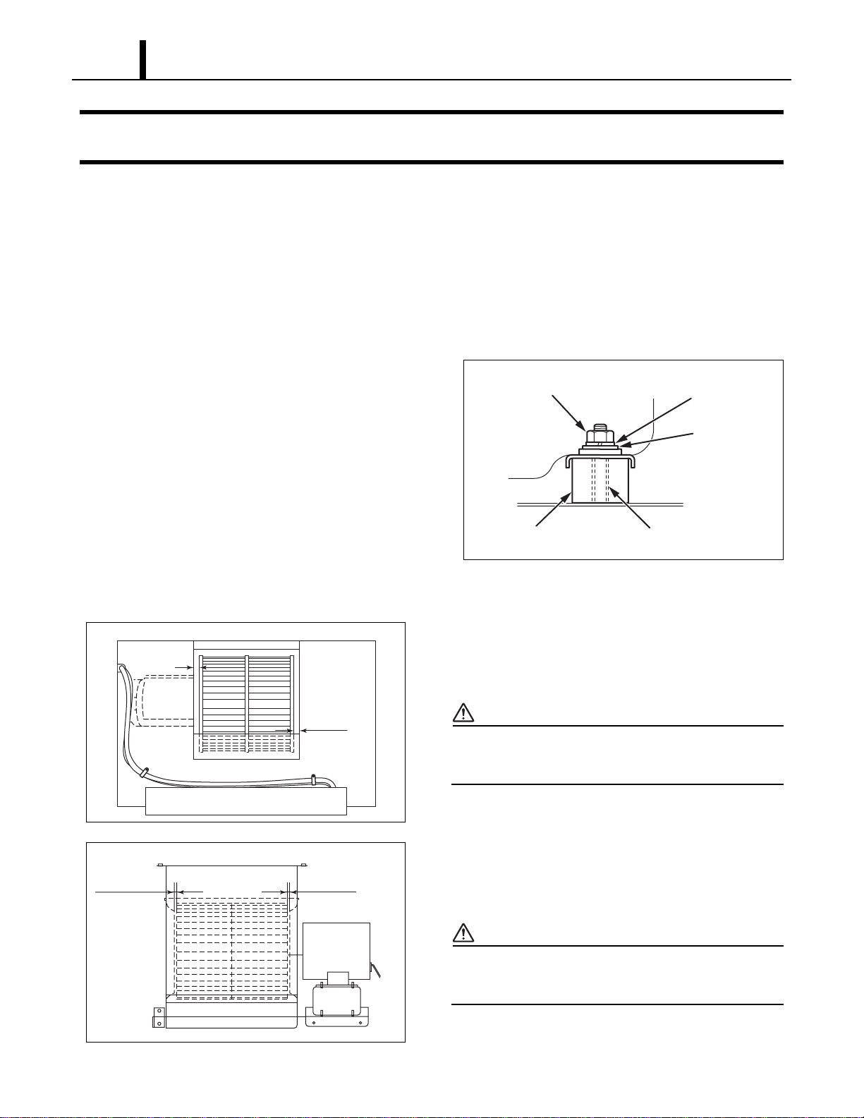
Repair Section
62
10. REASSEMBLY
10.1 Removal of Unit
• Reassemble the unit in the reverse order of removal. Described below are the parts that require
special care in reassembling the unit. Perform all wiring or rewiring as referenced in the wiring
diagram.
10.2 Compressor Mounting
• Mount the compressor on the frame, using
cushions, steel collars, spring washers, plate
washers and nuts.
10.3 Blower Assembly
1) Install blower fan for evaporator. Allow a
clearance of 0.12 in (3 mm) (minimum) on each
side of the evaporator fan.
CAUTION
•Tightening torque:
-10.84 ± 2.17 ft•lbf (15 ± 2.7 N•m)
2) Install blower fan for condenser. Allow a
clearance of 0.12 in (3 mm) (minimum) on each
side of the condenser fan.
CAUTION
•Tightening torque:
-10.84 ± 2.17 ft•lbf (15 ± 2.7 N•m)
I001818
Nut
Spring Washer
Steel Collar
Cushion
Plate Washer
I002229
Min 0.12 in
(3 mm)
Min 0.12 in
(3 mm)
<Evaporator Blower Assy>
I002283
Min 0.12 in
(3 mm)
Min 0.12 in
(3 mm)
<Condenser Blower Assy>
Repair Section
63
10.4 Wiring Notice
• Secure the wires using clamps so that they do not come into contact with the edges of the
structure, etc. Secure the wires using clamps in the same position they were before removal.
10.5 Perform the Inspection
• Perform the inspection of cooling performance and check for abnormal noise or abnormal
vibration.
10.6 Caster Maintenance
• Lubricate bearings in caster as needed with standard bearing grease using the zerk fitting.
< NOTE >
Casters should roll and swivel freely. Check for dirt or dust build up. Remove dust or dirt build up.
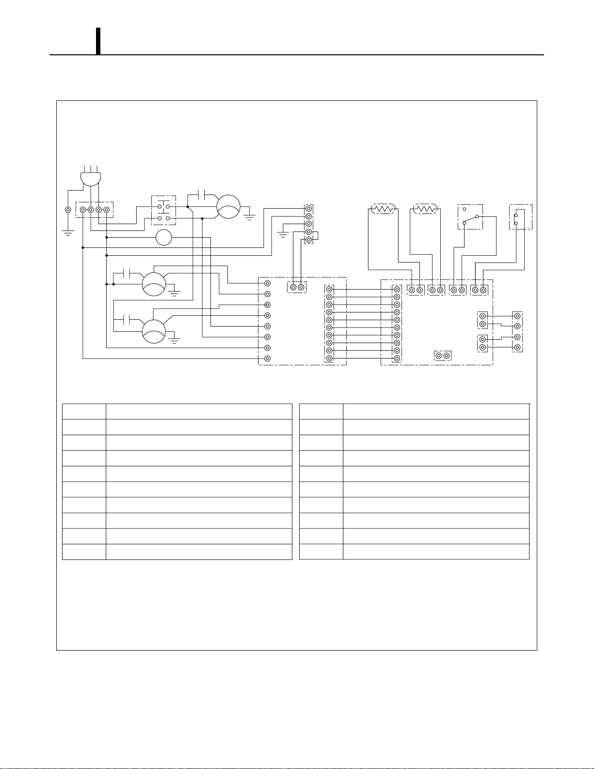
Repair Section
64
10.7 Schematic
I001821
AC 208/230 V 1φ 60 Hz
<Wiring Diagram>
AP
G
G
G
G
T1
TB1
L1
HI
HI
LO
LO
MF2
T1
L3
MCC
MCC
MC
CN RTH THS DS
CB
HPRS
TB2
L-
J106
J108
J105
J101 J102 J103 J104
J201
L+
E-
E+
3
2
1
Jumper
Line
IOLC
IOLF
MF1
IOLF
CC
12
CF2
12
CF1
12
G
G
T3
T RR1
J9
J10
RB
J8
J7
J6
J5
J4
J3
J2
J1
AP
TB1
TB2
CB
R B
MF1
MF2
MC
CF1
CF2
Attachment Plug
Terminal Block
Terminal Block
Control Board
Relay Board
Condenser Fan Motor
Evaporator Fan Motor
Compressor Motor
Capacitor for Condenser Motor
Capacitor for Evaporator Motor
CC
IOLF
IOLC
DS
THS
R TH
G
HPRS
CN
MCC
Capacitor for Compressor
Inner Overload Relay of Fan Motor
Inner Overload Relay of Compressor
Full Drain Warning Switch
Freeze Protection Thermistor
Room Thermistor
Grounding
High Pressure Switch
Connector for Option Condensate Pump
Relay for Compressor and Condenser Fan Motor

DENSO SALES CALIFORNIA, INC.
Long Beach, CA 90810
www.movincool.com
P/N: SV0001- 01 Second Issue: June 2008