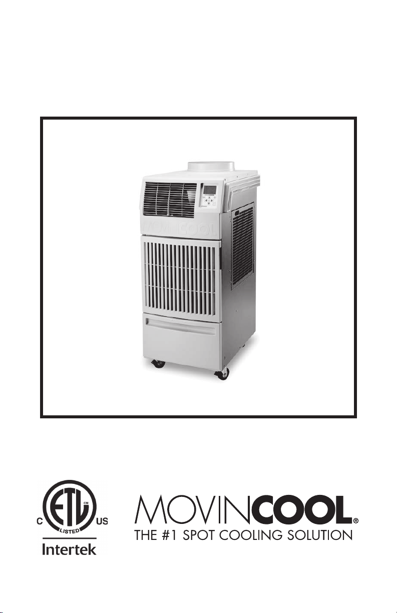
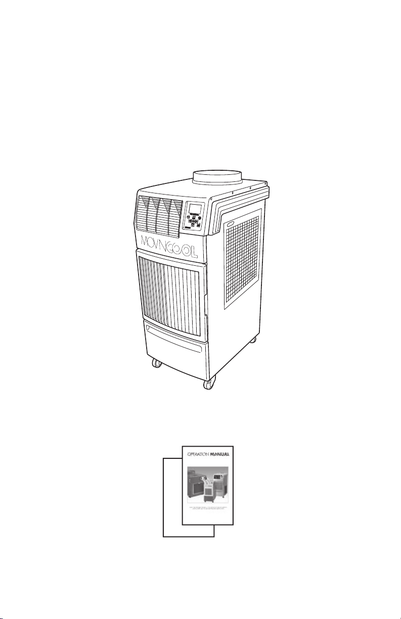
OPERATION MANUAL
CLIMATE PRO 18
Unit Serial Number Range: 0914XXXXH18 to Present
(From September 2014 to Present)
READ THIS MANUAL CAREFULLY FOR INSTRUCTIONS ON CORRECT
INSTALLATION AND USAGE, AND READ ALL SAFEGUARDS
SECCIÓN EN ESPAÑOL
SECTION EN FRANÇAIS
AVAILABLE AT WWW.MOVINCOOL.COM
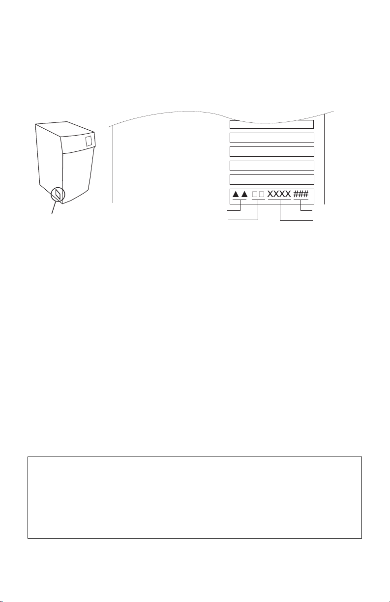
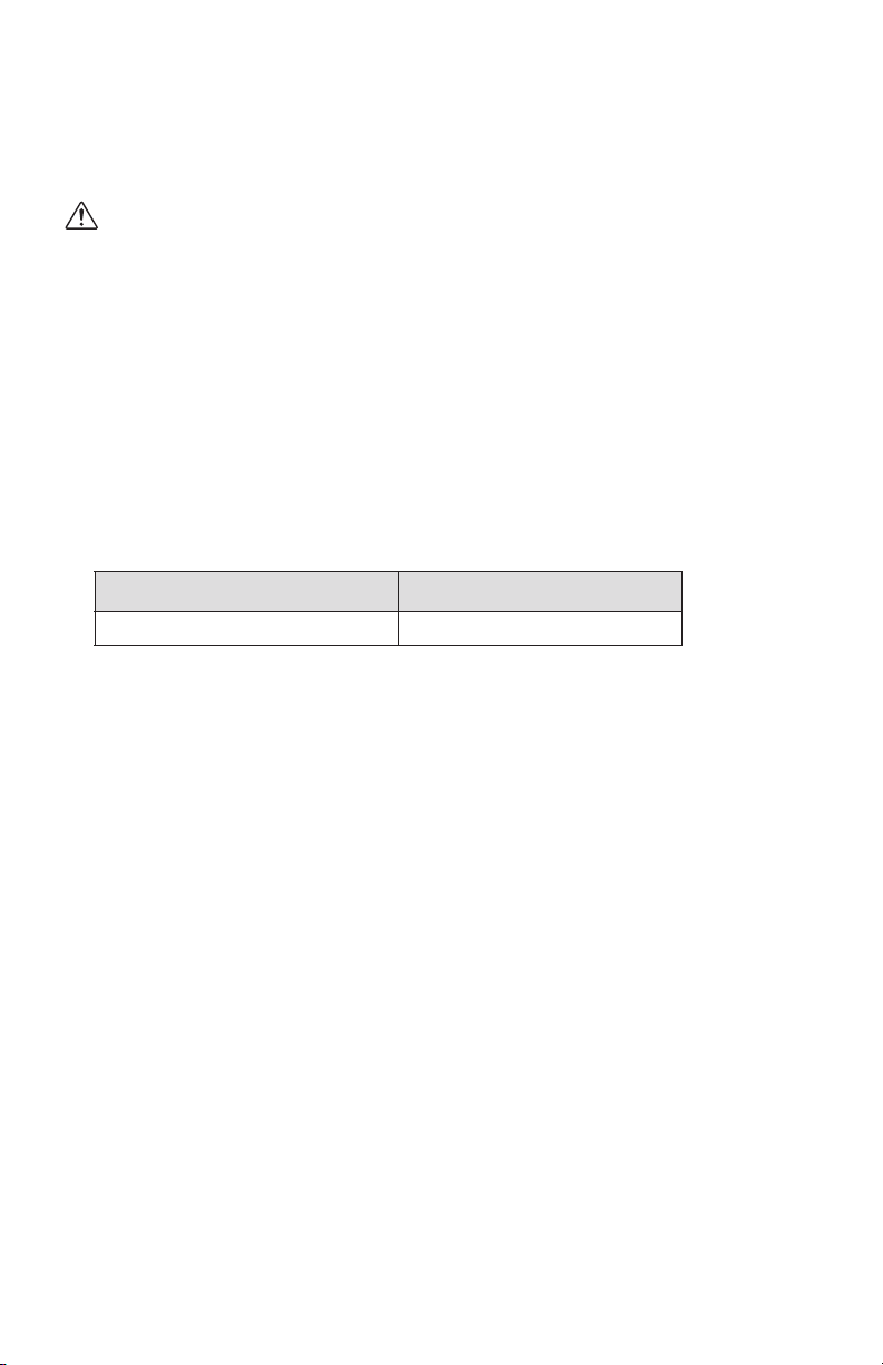
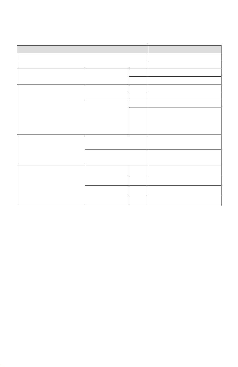
SERIAL NUMBER LOCATION AND IDENTIFICATION
Nameplate Label Position
Nameplate Label
COOLING AMPS. WITH PUMP
COMPR. OUTPUT
REFRIGERANT/TOTAL CHARGE
DESIGN PRESSURE LO/HI
PART NO./WEIGHT
SERIAL NO.
Month
Model
Sequential
Number
Year
© 2014 DENSO PRODUCTS AND SERVICES AMERICAS, INC.
All rights reserved. This book may not be reproduced or copied, in
whole or in part, without the written permission of the publisher.
DENSO PRODUCTS AND SERVICES AMERICAS, INC. reserves the
right to make changes without prior notice. MovinCool®, Office Pro®,
and SpotCool® are registered trademarks of DENSO Corporation.

OPERATION MANUAL
CLIMATE PRO 18

Table of Contents
SERIAL NUMBER LOCATION AND IDENTIFICATION ...................................2
FOREWORD ......................................................................................................5
Definition of Terms ..........................................................................................
...5
GENERAL WARNINGS & CAUTIONS..............................................................6
INVENTORY.......................................................................................................7
INSTALLATION .................................................................................................8
Choosing an Installation Site...........................................................................
..8
Moving the Unit ..................................................................................................
.9
Setup Configuration and Accessories .............................................................10
Plugging in the Unit ...........................................................................................11
LCDI Power Cord Instruction ............................................................................12
Test Procedure ............................................................................................................12
External Thermostat Connection....................................................................13
External Millivolt Thermostat Connection (Optional Accessory).....................13
External 24VAC Thermostat Connection (Field Supplied)...............................15
External Warning Device Connection ..............................................................16
External Alarm Device Connection ..................................................................18
FEATURES .......................................................................................................20
OPERATION .....................................................................................................21
Operation Modes................................................................................................21
Control Panel......................................................................................................22
LCD Indicators....................................................................................................23
Set Clock.............................................................................................................24
Cool Mode Operation.........................................................................................25
Heat Mode Operation .........................................................................................26
Fan Only Mode Operation .................................................................................27
Menu Features ....................................................................................................28
Key Lock and Unlock.........................................................................................28
Fan Mode Control...............................................................................................29
LCD Brightness Adjustment .............................................................................29
Changing Temperature Scale ...........................................................................30
Activating External Thermostat ........................................................................30
Program Operation and Schedule ....................................................................31
Setting Program..........................................................................................................31
Viewing Program .........................................................................................................32
Clearing All Program Slots........................................................................................32
Clearing Each Program Slot.......................................................................................33
Starting Program Operation .......................................................................................34
Stopping Program Operation .....................................................................................35
Self-Diagnostic Codes ..............................................................................
..........36
Emptying the Drain Tank...................................................................................39
Condensate Pump Kit (Optional Accessory)...................................................40
DAILY MAINTENANCE .....................................................................................41
Emptying the Drain Tank...................................................................................41
Air Filter Maintenance........................................................................................41
Removing the Air Filters .............................................................................................41
Cleaning the Air Filters ...............................................................................................41
SEASONAL MAINTENANCE ............................................................................42
In-Season ........................................................................................................
...42
Off-Season ......................................................................................................
...42
TROUBLESHOOTING ......................................................................................43
TECHNICAL SPECIFICATIONS.......................................................................46
WARRANTY STATEMENT...............................................................................48

5
FOREWORD
Congratulations on purchasing the MovinCool portable air conditioner. This
manual explains how to install and operate the MovinCool Climate Pro 18 portable
air conditioning unit. Please read this operation manual thoroughly to familiarize
yourself with the features of the unit and to ensure years of reliable operation.
You may also find it useful to keep this operation manual on hand for reference.
Components and/or procedures are subject to change without prior notice.
Definition of Terms
WARNING: Describes precautions that should be observed in order
to prevent injury to the user during installation or unit operation.
CAUTION: Describes precautions that should be observed in order
to prevent damage to the unit or its components, which may occur
during installation or unit operation if sufficient care is not taken.
Note: Provides additional information that facilitates installation or unit operation.

6
GENERAL WARNINGS & CAUTIONS
• All electrical work must be performed by qualified electrical personnel. Repair
to electrical components by non-certified technicians may result in personal
injury and/or damage to this unit. All electrical components replaced must be
genuine MovinCool parts, purchased from an authorized dealer.
• The power source for this unit should be a dedicated single outlet circuit with
UL recognized short-circuit and ground fault protective breaker.
• Because of potential safety hazards under a certain condition, we strongly
recommend against the use of an extension cord.
However, if you still elect to use an extension cord, it is absolutely necessary
that it is a UL listed, 3-wire grounding type appliance extension cord, having a
3-blade and a 3-slot receptacle that plugs into the appliance.
The marked rating of the extension cord should be 120 V, 20 A or equivalent.
• This unit is equipped with a 10 feet (3 m) UL recognized LCDI power cord.
If replacement, fixed location (hard wired) or power cord lengthening
(extension cord) is requried, contact your dealer or a qualified electrician for
approved methods.
• Never fold or place heavy objets on the power cord.
This could result in damage to the power cord causing electrical shock or fire.
• Turn this unit off and unplug the power cord when the power cord is damaged.
• Do not place water or any other liquid on this unit. This can cause damage to
the unit and increase the risk of electrical shock.
• Do not use water to clean inside this unit. Exposure to water can destroy the
insulation and electrical components, leading to electric shock.
• Interior cleaning of this unit must be performed by authorized personnel only.
Consult your MovinCool dealer.
• Do not sit or stand on this unit.
7
INVENTORY
After unpacking your MovinCool unit, please check to make sure you have the
following items:
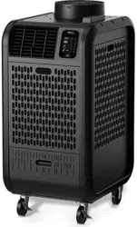
1. Climate Pro 18 Unit (1)
2. Operation Manual (1)
3. Product Registration (1)
Note: If any of these items were not included in the box or appear damaged,
please contact your MovinCool dealer for replacement.
ILL00772-00
Climate Pro 18 Unit
ILL00042-02
Operation Manual
Product Registration
8
INSTALLATION
Choosing an Installation Site
CAUTION: Following are some precautions to consider before
choosing your installation site. Please review carefully as improper
installation may result in personal injury or damage to the unit.
• Do not use the unit in areas where leakage of flammable gas may occur.
• Do not use the unit in areas where it is exposed to rain or water.
• Do not use the unit in an environment which contains excessive amounts of
corrosive gas or vapor.
• Do not use in areas where the temperature is outside the allowable operating
range.
• Do not install the unit in sloping areas. The unit may move or topple over even
if the casters are set to the LOCKED position.
• Install the unit in areas where can withstand the weight of the unit.
*1: Approximate weight when the drain tank is full of water.
• Allow 24 inch (610 mm) of unobstructed airflow for both the air inlets and
outlets.
Model
Unit Weight
*1
Climate Pro 18 256 lb (116 kg)
9
INSTALLATION (cont.)
Moving the Unit
Unlock the casters and push the MovinCool unit using the side handles to a flat,
level surface and set the casters back to the LOCKED position.
ILL00773-00
Left Side Handle
Right Side Handle
ILL00044-01
Locked
Unlocked
10
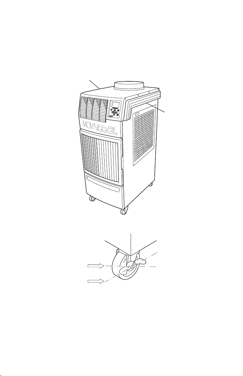
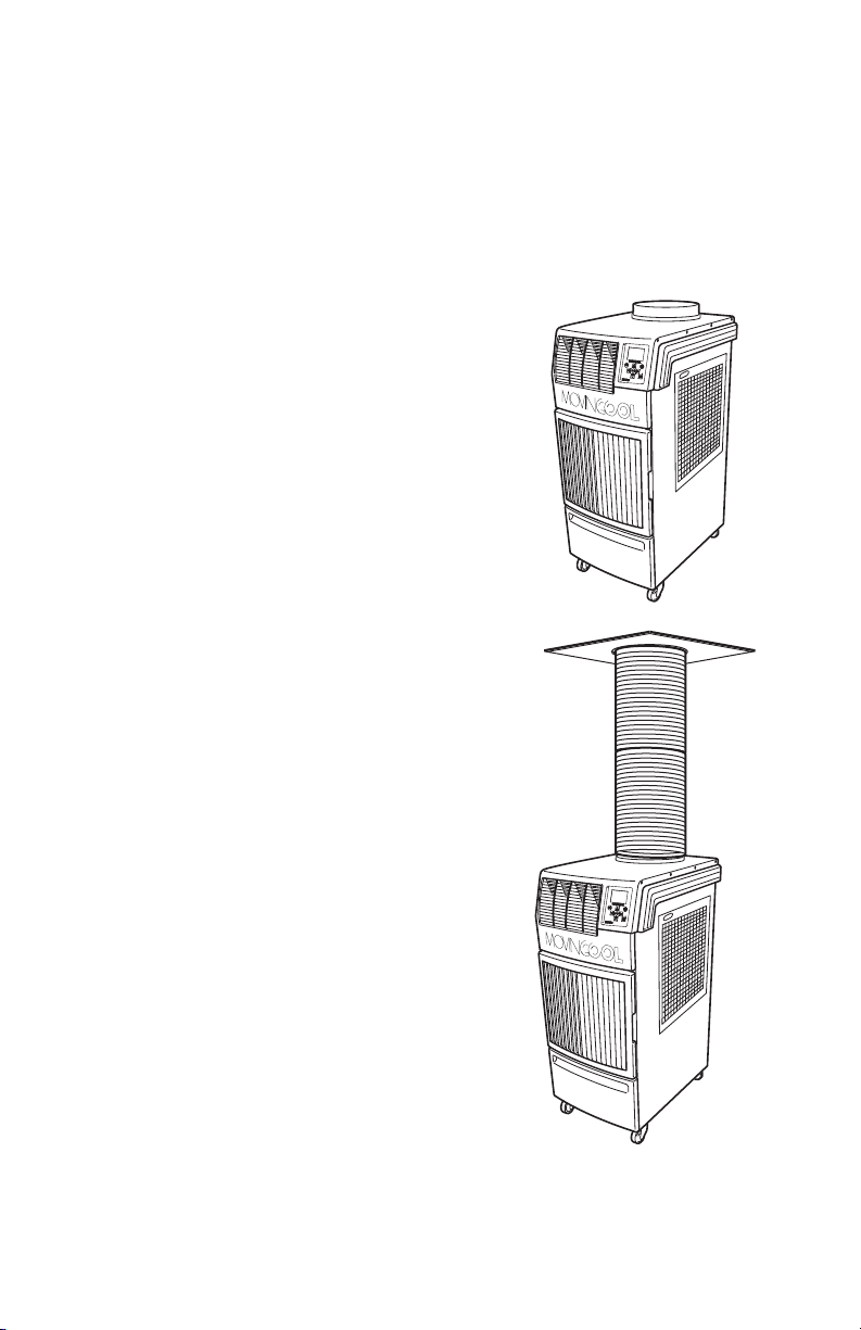
INSTALLATION (cont.)
Setup Configuration and Accessories
The Climate Pro 18 works more efficiently with optional accessories set up and
configured for cooling and heating application. The most common setup
configurations are:
1. Spot Cooling/Heating Configuration
2. Single Duct Cooling/Heating
Configuration
ILL00804-00
ILL00805-00
11
INSTALLATION (cont.)
Plugging in the Unit
1. Check the prongs and surface of the power cord plug for dust/dirt. If dust and/
or dirt are present, wipe off with a clean, dry cloth.
2. Check the power cord, plug and prongs for damage or excess play. If any
damage or excess play is found, contact your MovinCool dealer for
replacement.
WARNING:
• If the power cord or plug is damaged, replacement must be
performed by qualified electrical personnel.
• Do not connect or disconnect the power cord or attempt to operate
buttons with wet hands. This could result in electrical shock.
• Because of potential safety hazards under a certain condition, we
strongly recommend against the use of an extension cord. However,
if you still elect to use an extension cord, it is absolutely necessary
that it is a UL listed, 3-wire grounding type appliance extension cord,
having a 3-blade and a 3-slot receptacle that plugs into the
appliance. The marked rating of the extension cord should be the
following rating or equivalent.
3. Check the power supply outlet rating and fuse size to match with table below.
CAUTION: The power source should be a dedicated single outlet
circuit with UL recognized short-circuit and ground fault protective
breaker. Do not share the power supply outlet with any other
instrument or equipment. The minimum power supply rating and
the recommended fuse size are listed above.
Note:
• Make sure the power supply outlet is free of dirt, dust, oil, water, or any other
foreign matter.
• The Climate Pro 18 is equipped with UL recognized LCDI cord and NEMA plug
configuration (5-20). The appropriate outlet must be used for this plug type.
Model Rating of Extenstion Cord
Climate Pro 18 120 V, 20 A
Model Minimum Power Supply Rating Recommended Fuse Size
Climate Pro 18 115 V, 1 Phase, 60 Hz, 20 A 20 A maximum
12
INSTALLATION (cont.)
LCDI Power Cord Instruction
WARNING: This LCDI power cord is a non-serviceable device.
Attempting to open the device may expose the user to the hazards
of electric shock, and could void warranties of this product.
Manufacture’s reliability is limited to the replacement of the device.
CAUTION:
• Read the attention printed on the device for proper use and handling
of this device.
• This device is used for monitoring leakage current.
• Do not immerse in water.
• This device must only be plugged into an appropriate wall outlet. Do
not remove the ground prong.
• In the event that this device trips, the cause of malfunctions should
be corrected first before further use.
• Using the device beyond the recommended voltage poses risk to
users.
• Conductors inside this cord are surrounded by shields, which
monitor leakage current.
• These shields are not grounded, and they are periodically examined
for any damage.
Do not use this product in the event the shields become exposed.
• Do not repleatedly push TEST and/or RESET buttons.
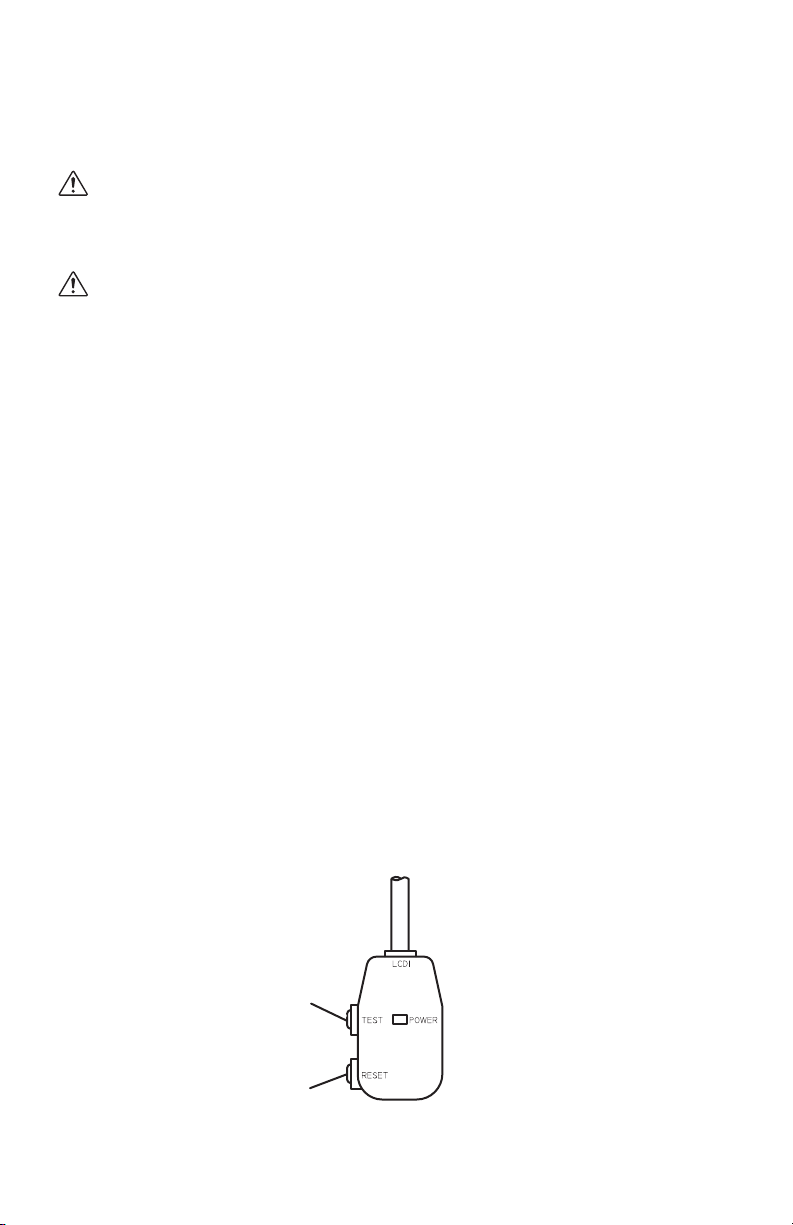
Test Procedure
Test this device once when the power supply is installed to assure proper
operation.
1. Plug into the grounded power receptacle.
2. If POWER light is not on, press RESET button once. Light should turn on.
3. Press TEST button once, POWER light must turn off.
4. Press RESET button once again for use. POWER light should turn on.
5. If this test fails, do not use this device. Contact a qualified technician for
details.
Reset Button
Test Button
<Front View>
ILL00049-01
13
INSTALLATION (cont.)
External Thermostat Connection
External Millivolt Thermostat Connection (Optional Accessory)
WARNING:
• All electrical work must be performed by qualified personnel.
CAUTION : Do not install the millivolt thermostat where artificial
heating condition may occur (i.e. hot stove, hot pipe, and
fireplace or under direct sunlight.)
Otherwise it may result in personal injury and/or damage to the unit.
• Disconnect power before installation. Beware that some residual
voltage may remain in the unit immediately after the power is
disconnected.
1. Select the proper location where the millivolt thermostat can be conveniently
accessed and install it at the selected location.
2. Set the millivolt thermostat to cool or heat mode without power connection
on the unit.
3. Prepare the millivolt thermostat wires.
Recommended wire size: 18 ~ 20 AWG
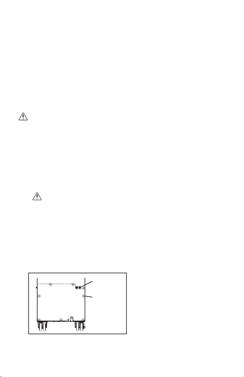
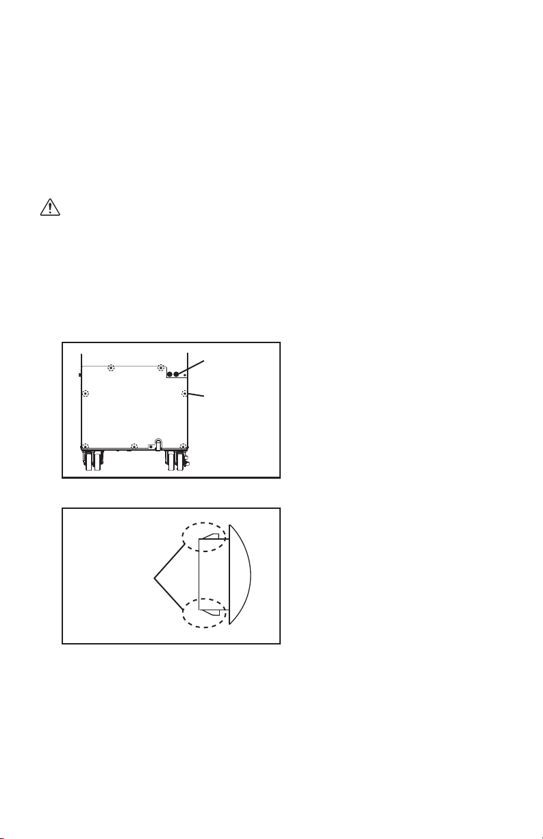
4. Turn the unit off and unplug the power cord.
5. Take out seven (7) screws and remove the service panel from rear of the unit.
Screws (7)
Cap
ILL00806-00
The Climate Pro 18 comes with two types of external thermostat connections
available to be connected with:
a. An optional 24VAC transformer is required with a field supplied 24VAC
thermostat. Follow the instruction steps provided with an optional 24VAC
transformer for this connection.
b. A MovinCool optional millivolt thermostat. Follow the steps below for the
connection of a millivolt thermostat.
14
INSTALLATION (cont.)
External Thermostat Connection (cont.)
External Millivolt Thermostat Connection (Optional Accessory)
(cont.)
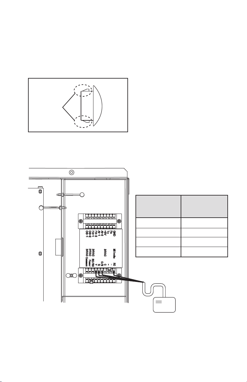
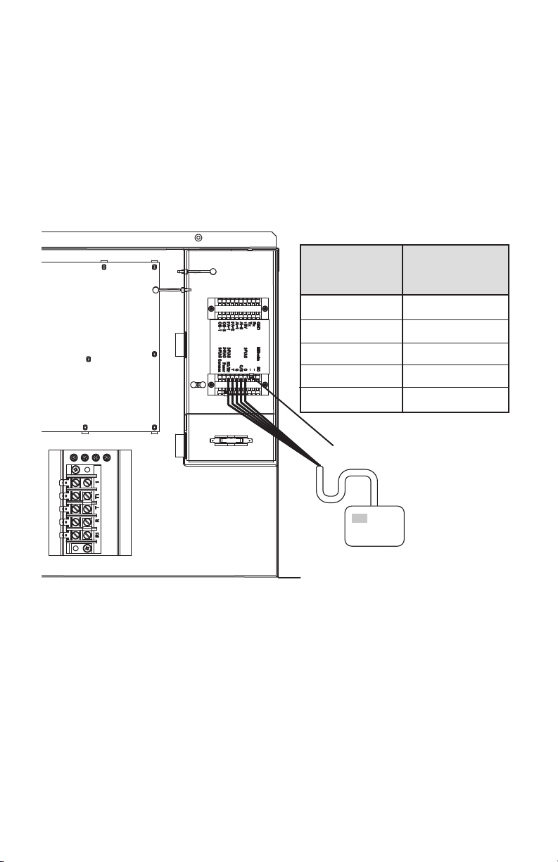
7. Insert the millivolt thermostat wires through the hole in the rear panel.
8. Connect the millivolt thermostat wires to the terminal block according to
the connection table shown below.
9. Reinstall the service panel to the unit.
10. Refer to page 30 for activating an external thermostat on the unit’s control
panel.
Connection Table
RC
O/B
Millivolts RC
Millivolt
Thermostat
Wire No.
Unit
Terminal Block
Terminal No.
O/B
GG
Y
Y
Millivolt Thermostat
Service Box
ILL00776-00
6. Squeeze the inner latches and push out the black cap from inside the panel.
ILL00046-01
Latch
Cap
15
INSTALLATION (cont.)
External Thermostat Connection (cont.)
External 24VAC Thermostat Connection (Field Supplied)
The Climate Pro 18 can also be connected with the external 24VAC thermostat
where the 24VAC is readily available, simply follow the steps and connection
table below.
Note: Keep this jumper plug in a safe place to reuse when the 24VAC
thermostat is removed from the unit.
4. Reinstall the service panel to the unit.
5. Refer to page 30 for activating an external thermostat on the unit’s control
panel.
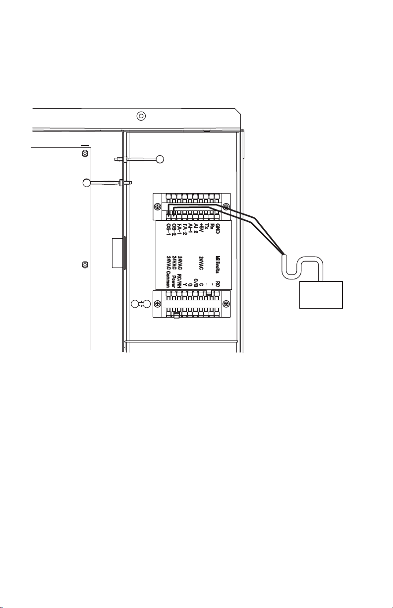
1. Refer to the previous section to remove the service panel and insert the
thermostat wires through the hole in the rear panel.
2. Connect the 24VAC thermostat wires to the terminal block according to the
connection table shown above.
3. Remove the jumper connector from the terminal block.
ILL00777-00
Connection Table
24VAC RC/RH
24VAC C
24VAC
Wall Thermostat
Wire No.
Unit
Terminal Block
Terminal No.
O/B
G
Y
C
O/B
RC/RH
G
Y
Jumper Connector
24VAC Wall Thermostat
Service Box
16
INSTALLATION (cont.)
External Warning Device Connection
The controller of this unit is equipped with a warning signal output relay which can
be used to monitor failure condition of the unit and is compatible with various
external warning devices such as alarm speaker, light indicators, etc.
Relay type: Form C, normal open dry contact
Relay output contactor rating: 2 A at 30 V (DC/AC) or less (resistive load)
WARNING:
• All electrical work must be performed by qualified personnel.
Otherwise it may result in personal injury and/or damage to the unit.
• Disconnect power before installation. Beware that some residual
voltage may remain in the unit immediately after the power is
disconnected.
1. Turn the unit off and unplug the power cord.
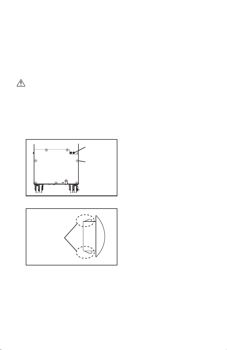
2. Take out seven (7) screws and remove the service panel from rear of the unit.
3. Squeeze the inner latches and push out the black cap from inside the panel.
4. Insert the warning signal wires through the hole in the rear panel.
Recommended wire size: 16 AWG ~ 22 AWG
Screws (7)
Cap
ILL00806-00
ILL00046-01
Latch
Cap
17
INSTALLATION (cont.)
External Warning Device Connection (cont.)
5. Connect the warning signal wires to the terminals OS-1 and OS-2 as shown
in the above figure.
6. Reinstall the service panel to the unit.
Service Box
Warning Device
ILL00774-00
18
INSTALLATION (cont.)
External Alarm Device Connection
The controller of this unit is equipped with two sets of input signal terminals on the
terminal block which can connect the external alarm devices such as a fire alarm
device. The input signal terminals should only be connected to a close or an open
dry contact. When receiving the signals from the external alarm devices, the unit
turns off and does not turn back on until it has been RESET.
WARNING:
• All electrical work must be performed by qualified personnel.
Otherwise it may result in personal injury and/or damage to the unit.
• Disconnect power before installation. Beware that some residual
voltage may remain in the unit immediately after the power is
disconnected.
1. Turn the unit off and unplug the power cord.
2. Remove seven (7) screws and remove the service panel from rear of the unit.
3. Squeeze the inner latches and push out the black cap from inside the panel.
4. Insert the alarm signal wires through the hole in the rear panel.
Recommended wire size: 16 AWG ~ 22 AWG
Screws (7)
Cap
ILL00806-00
ILL00046-01
Latch
Cap
19
INSTALLATION (cont.)
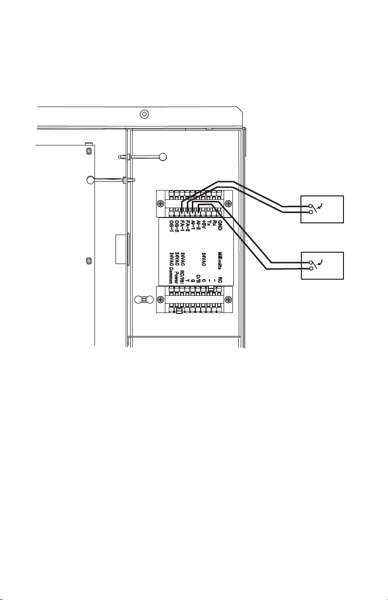
External Alarm Device Connection (cont.)
5. Connect the alarm signal wires to terminal AI-1 and AI-2 and/or FA-1 and FA-
2 as shown in the above figure.
6. Reinstall the service panel to the unit.
ILL00775-00
Service Box
Alarm Device 1
Alarm Device 2

20
FEATURES
1. Digital electronic control panel, which allows the user to easily control the
unit’s operation.
2. Three fan speeds (HI, MID, LO) in all modes (COOL, HEAT, FAN ONLY).
3. Large digital LCD display with two backlight colors and multiple lines of
displayed characters that indicate:
• Clock with day and time
• Room temperature and set point temperature (°F or °C)
• Cool, Heat, and Fan Only mode status
• Fan speed and fan mode status
• Confirmation screen to confirm selection status
• Notification screen when an external thermostat is connected
• Program set up and schedule to run and stop
• Self-diagnostic codes with explanation
4. The set point temperature can be adjusted to maximum or minimum value
depending on selected COOL or HEAT mode.
5. Automatic restart feature when the power is lost and regained. The unit returns
to the same operation mode as it was prior to the loss of power. Any preset
program is retained in the memory in the event power loss occurs.
6. Up to ten program slots are available to the user to program a specific time
and day at which the unit automatically begins to operate and turn off.
7. Drain tank and optional condensate pump warning display with instruction.
8. Automatic shut off, warning signal output and alarm for temperature sensor
failure, loss of cooling, and conditions of self-diagnostic codes.
9. External millivolt or 24VAC thermostat connection.
10. External alarm and warning device connection with automatic shut off.

21
OPERATION
Operation Modes
The Climate Pro 18 operates in three modes, COOL, HEAT, and FAN ONLY.
The unit is in standby mode if it is not operating in these modes.
• Standby Mode
When the unit is connected to power, the LED illuminates in orange color,
and the LCD displays date, time and the previous mode setting condition
with blue backlight that stays on for 60 seconds, then turns off. The backlight
turns on again if any button is pressed.
• Cool Mode
When the unit is in COOL mode operation, the compressor operates and cool
air is circulated. Once the room temperature reaches the set point temperature,
the unit operates in FAN ONLY mode. When switched from HEAT to COOL
mode operation, the unit initially operates in FAN ONLY mode.
Set point temperature range: 65 °F ~ 90 °F (18 °C ~ 32 °C)
• Heat Mode
When the unit is in HEAT mode operation, the compressor operates and hot air
is circulated. Once the room temperature reaches the set point temperature, the
unit stops. When switched from COOL to HEAT mode operation, the unit stops
until the compressor operates.
Set point temperature range: 55 °F ~ 80 °F (13 °C ~ 27 °C)
Note:
• When FAN mode is set to AUTO, the fan operates within 1 minute after the
compressor operates.
• When the ambient temperature falls outside the operating condition range, the
unit automatically stops and displays “OUTSIDE OPERATING RANGE” on
the control panel.
• When the ambient temperature is low, the unit automatically stops and starts
defrosting operation for maximum 15 minutes (“DEFROST” is displayed on
the control panel). The unit returns to heating operation after defrosting
operation is completed.
• Temperature Control
The room temperature thermistor monitors the inlet air temperature versus set
point temperature and automatically switches ON and OFF during cooling or
heating operation.
• Fan Mode Control
The fan mode control determines whether the fan continues to operate or stop
when the compressor stops during COOL or HEAT mode. The unit has been
preset at the factory for continuous fan operation in COOL and for fan AUTO
operation in HEAT mode. Fan mode can be changed on the control panel under
Menu mode.
• Temperature Scale Display
The unit has been preset at the factory to display the temperature in °F. The
temperature scale can be changed from °F to °C on the control panel under
Menu mode.
22
OPERATION (cont.)
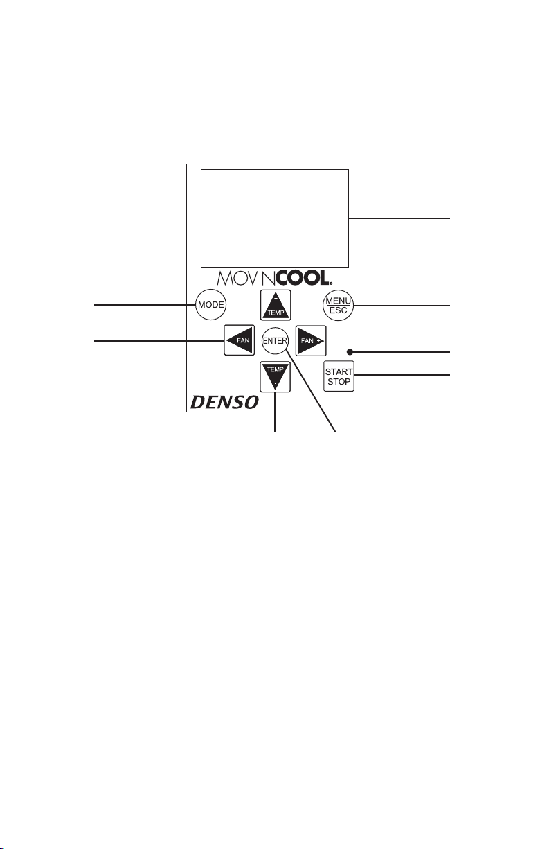
Control Panel
Before operating the unit, it is important to familiarize yourself with the basic
controls located on the control panel.
1. START/STOP Button Start or stop the unit operation.
citsongaiD-fleS rof roloc egnarO ni etanimullIDEL.2
and Standby mode, in Green color for normal
operation.
3. MODE Button Select operation mode (Fan Only, Cool, and
Heat).
4. MENU/ESC Button
escape from the menu selection screen.
Display the menu selection screen or to
5. ENTER Button Select item in Menu mode.
6. FAN+, -FAN Buttons Change fan speeds Hi, MID, LO.
7. TEMP+, -TEMP Buttons Change set point temperature.
,noitacifiton ,sutats ,edom noitarepo yalpsiDDCL.8
confirmation, and self-diagnostic codes with
two backlight colors.
lLL00778-00
1
7
2
4
8
5
3
6
23
OPERATION (cont.)
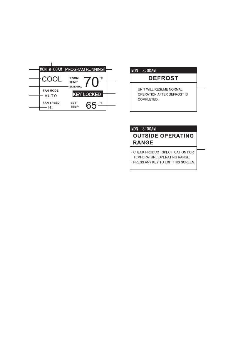
LCD Indicators
1. Day of the week Indicate day of the week.
2. Time of the day Indicate time of the day.
3. Room Temp Indicate room temperature.
4. Key Locked Indicate keypad is locked.
5. Set Temp Indicate set point temperature.
6. Fan Only/Cool/Heat Indicate operating mode.
7. Fan Mode Indicate AUTO or ON.
8. Fan Speed Indicate HI, MID or LO.
9. External Indicate external millivolt or 24VAC
thermostat is connected.
10. Program Running Indicate Program is running
.gnitaeh gnirud noitarepo tsorfed etacidnItsorfeD.11
12. Outside Operating Range Indicate the unit is used outside of the
operating condition range.
lLL00779-00
1
6
9
7
8
10
3
4
5
2
lLL00780-00
11
ILL00781-00
12
24
OPERATION (cont.)
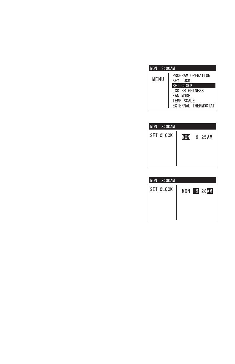
Set Clock
Prior to operating the Climate Pro 18, set the clock of the controller to the correct
time as shown in the following steps.
1. Press MENU button to go to MENU.
2. Use TEMP+ or -TEMP button to select SET
CLOCK. Press ENTER button to start setting
day of the week, hour, and minute.
3. Use TEMP+ or -TEMP button to select day of
the week, then press ENTER button to confirm.
Follow the same procedure to set hour and
minute.
4. Once the minute has been selected, press
ENTER button to complete, LCD automatically
exits from SET CLOCK to the previous mode.
Note:
• If no button is pressed for 1 minute, LCD automatically displays the previous
mode.
• Please check clock periodically to confirm clock accuracy.
ILL00782-00ILL00782-00
ILL00783-00
ILL00784-00
25
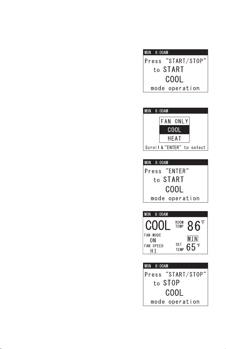
OPERATION (cont.)
Cool Mode Operation
1. If the unit is in standby mode, simply press
MODE button until “COOL” appears, then press
START/STOP button. LCD displays a
confirmation screen. Press START/STOP
button once again to start COOL mode
operation. LED color changes from orange to
green.
Note: If no button is pressed for 1 minute, LCD
automatically displays the previous mode.
2. If the unit is already in operation, press MODE
button once. The operation status screen
displays the current operation mode. Press
TEMP+ or -TEMP button to go to COOL, then
press ENTER button to select.
3. LCD displays a confirmation screen as shown
on the right.
4. Use TEMP+ or -TEMP button to change set
point temperature. LCD displays “MIN” or
“MAX” when set point value is at minimum or
maximum.
5. Use FAN+ or -FAN button to change fan speed
(HI, MID, LO).
6. To stop COOL mode operation, press START/
STOP button. LCD displays a confirmation
screen. Press START/STOP button again. LED
color changes from green to orange.
ILL00785-00
ILL00786-00
ILL00787-00
ILL00788-00
ILL00789-00
26
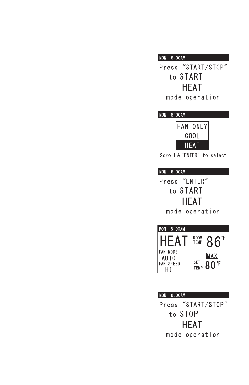
OPERATION (cont.)
Heat Mode Operation
1. If the unit is in standby mode, simply press
MODE button until “HEAT” appears, then press
START/STOP button. LCD displays a
confirmation screen. Press START/STOP button
once again to start HEAT mode operation. LED
color changes from orange to green.
Note: If no button is pressed for 1 minute, LCD
automatically displays the previous mode.
2. If the unit is in already in operation, press
MODE button once. The operation status
screen displays the current operation mode.
Press TEMP+ or -TEMP button to go to HEAT,
then press ENTER button to select.
3. LCD displays a confirmation screen as shown
on the right.
4. Use TEMP+ or -TEMP button to change set
point temperature. LCD displays “MIN” or
“MAX” when set point value is at minimum or
maximum.
5. Use FAN+ or -FAN button to change fan speed
(HI, MID, LO).
Note: When the ambient temperature is high,
fan speed is automatically changed from LO to
MID during HEAT mode operation.
6. To stop HEAT mode operation, press START/
STOP button. LCD displays a confirmation
screen. Press START/STOP button again. LED
color changes from green to orange.
ILL00790-00
ILL00791-00
ILL00792-00
ILL00793-00
ILL00794-00
27
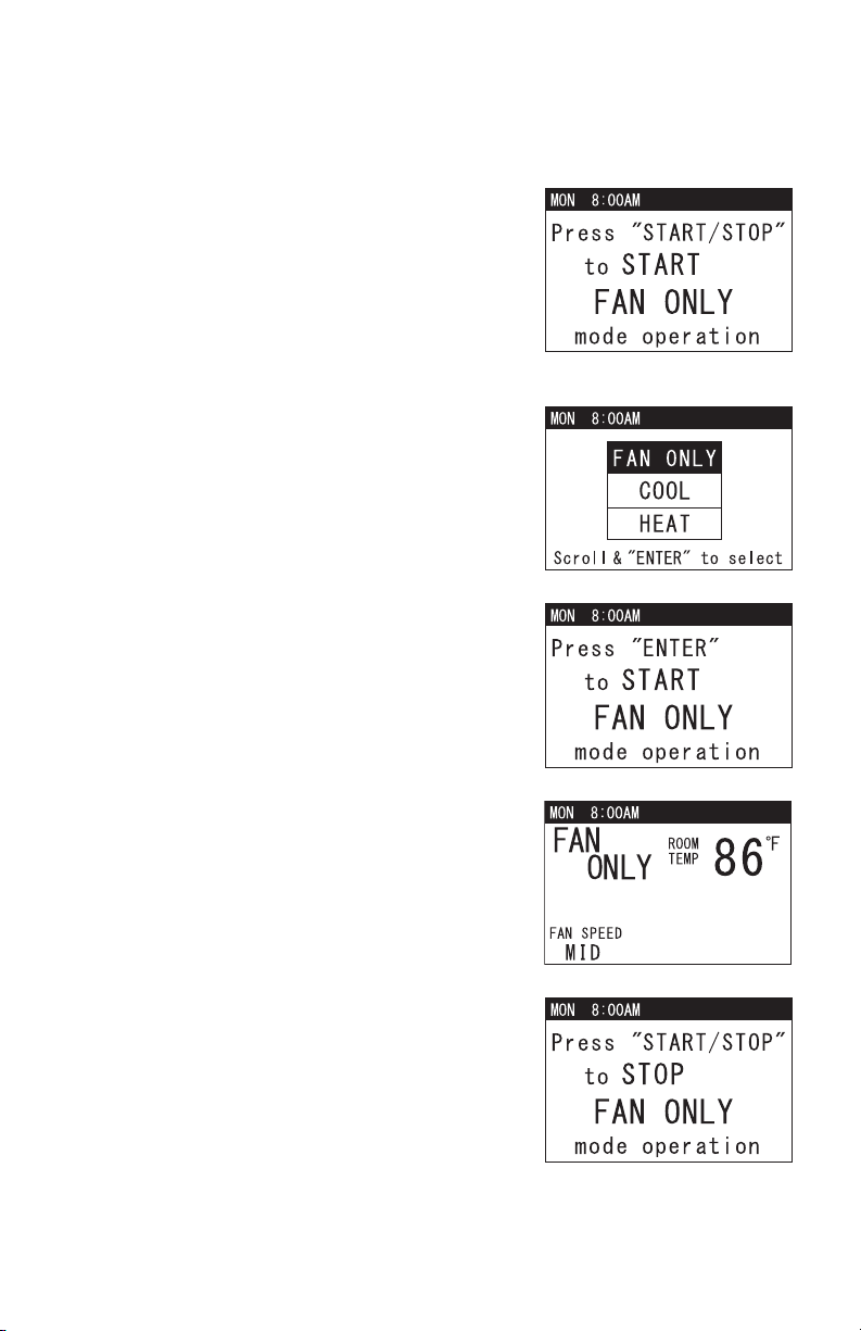
OPERATION (cont.)
Fan Only Mode Operation
1. If the unit is in standby mode, simply press
MODE button until “FAN ONLY” appears, then
press START/STOP button. LCD displays a
confirmation screen. Press START/STOP
button once again to start FAN ONLY mode
operation. LED color changes from orange to
green.
Note: If no button is pressed for 1 minute, LCD
automatically displays the previous mode.
2. If the unit is in operation, simply press MODE
button once. The operation status screen
displays the current operation mode. Press
TEMP+ or -TEMP button to go to FAN ONLY,
then press ENTER button to select.
3. LCD displays a confirmation screen as shown
on the right.
4. Use FAN+ or -FAN button to change fan speed
(HI, MID, LO).
5. To stop FAN ONLY mode operation, press
START/STOP button. LCD displays a
confirmation screen. Press START/STOP
button again. LED color changes from green to
orange.
ILL00795-00
ILL00796-00
ILL00797-00
ILL00798-00
ILL00799-00
28
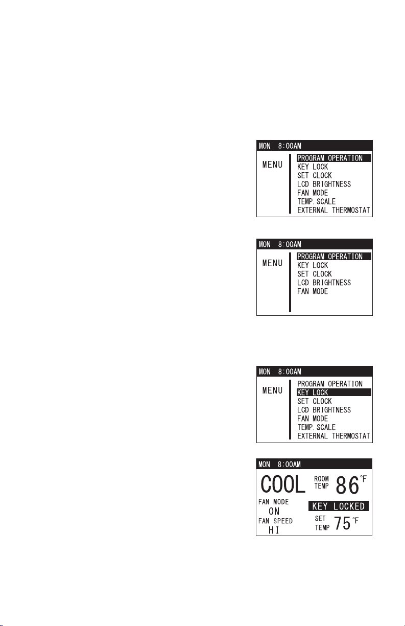
OPERATION (cont.)
Menu Features
The Climate Pro 18 has an on-screen Menu feature to easily change the setting
by using buttons on the control panel. Features in Menu are limited when
accessed during operation due to safety reason. All features in Menu are
accessible in standby mode.
1. Press MENU/ESC button during standby mode
or operation mode.
2. Use TEMP+ or -TEMP button to select the
feature and press ENTER button to confirm.
Note:
• Press MENU/ESC button again to return to the
previous screen or exit Menu.
• If no button is pressed for 1 minute, LCD displays
the previous mode.
Key Lock and Unlock
Key lock is a feature under Menu and disables all buttons on the control panel
except MENU/ESC button.
1. Press MENU/ESC button to go to MENU. Use
TEMP+ or -TEMP button to select KEY LOCK.
Select YES and press ENTER button to lock the
buttons. LCD displays “KEY LOCKED”.
2. To unlock the buttons, press and hold MENU/
ESC button for 5 seconds.
Note:
• Press MENU/ESC button again to return to the
previous screen or exit Menu.
• If no button is pressed for 1 minute, LCD displays
the previous mode.
• All buttons are automatically unlocked when a
self-diagnostic code is displayed.
ILL00800-00
Menu features during standby mode
ILL00801-00
Menu features during operation mode
ILL00802-00
ILL00803-00
29
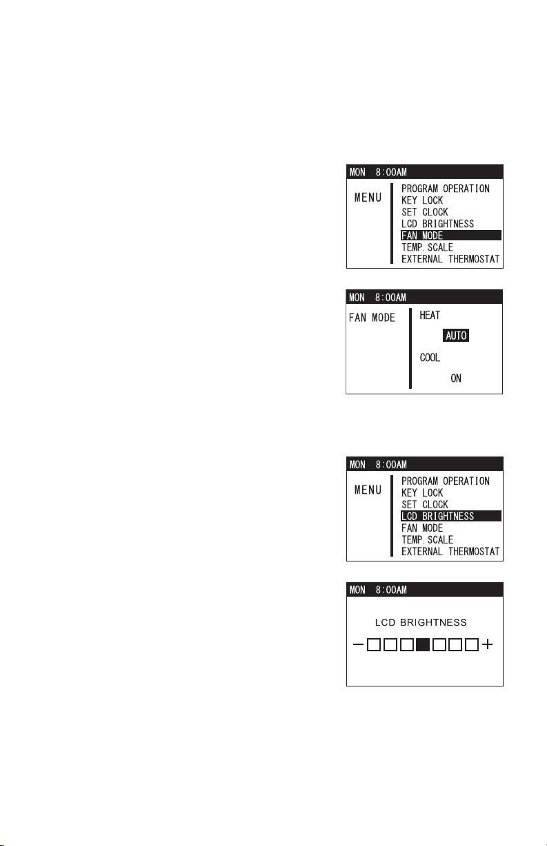
OPERATION (cont.)
Fan Mode Control
The fan mode control determines whether the fan continues to operate or stop
when the room temperature reached the set point temperature. The unit has been
preset at the factory for continuous fan operation.
1. Press MENU/ESC button to go to MENU.
Note: If no button is pressed for 1 minute, LCD
displays the previous mode.
2. Use TEMP+ or -TEMP button to select FAN
MODE and press ENTER button to confirm.
3. Use TEMP+ or -TEMP button to select fan
mode for heating or cooling, then use FAN+ or
-FAN button to select AUTO or ON and press
ENTER button to confirm.
LCD Brightness Adjustment
1. Press MENU/ESC button to go to MENU.
Note: If no button is pressed for 1 minute, LCD
displays the previous mode.
2. Use TEMP+ or -TEMP button to select LCD
BRIGHTNESS and press ENTER button to
confirm.
3. Use FAN+ or -FAN button to adjust the
brightness level, then press ENTER button to
confirm. The LCD automatically displays the
previous mode.
ILL00807-00
ILL00808-00
ILL00809-00
ILL00810-00
30
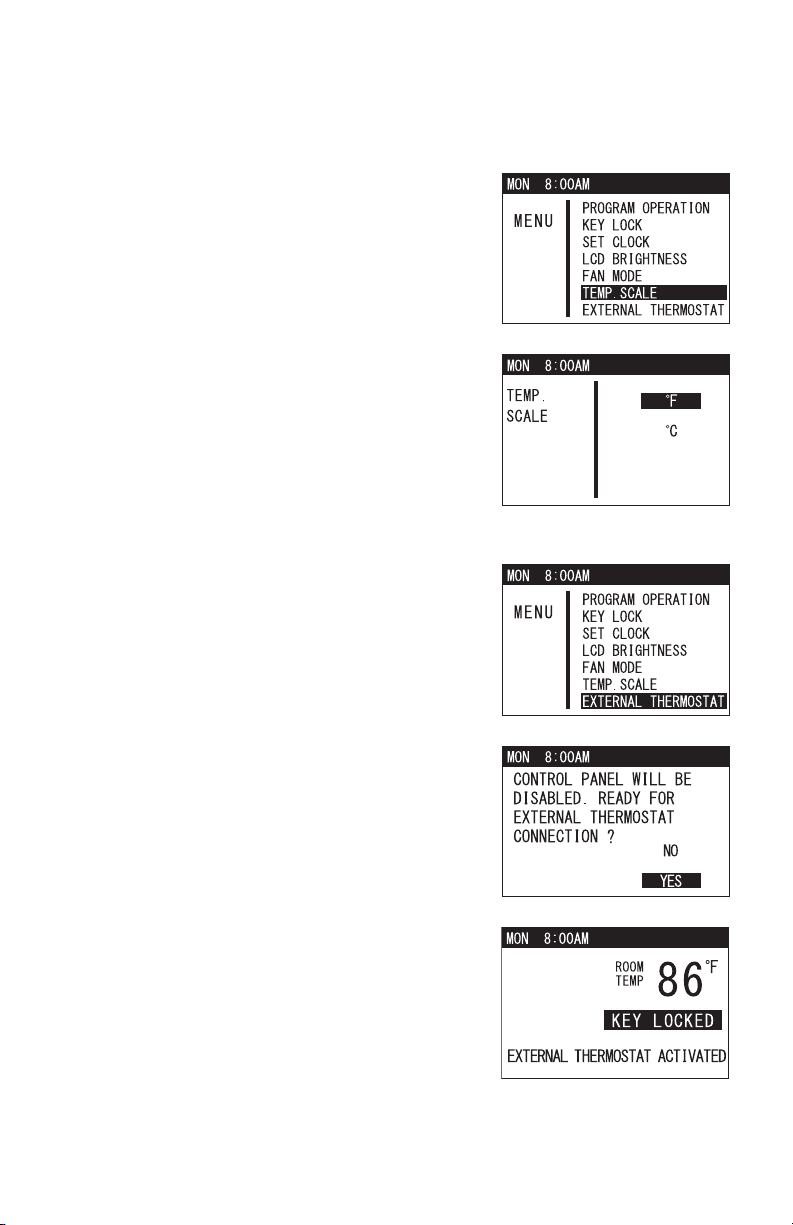
OPERATION (cont.)
Changing Temperature Scale
1. Press MENU/ESC button to go to MENU.
Note: If no button is pressed for 1 minute, LCD
displays the previous mode.
2. Use TEMP+ or -TEMP button to select TEMP.
SCALE and press ENTER button to confirm.
3. Use TEMP+ or -TEMP button to select °F or
°C and press ENTER button to confirm.
Activating External Thermostat
1. Press MENU/ESC button to go to MENU.
Note: If no button is pressed for 1 minute, LCD
displays the previous mode.
2. Use TEMP+ or -TEMP to select EXTERNAL
THERMOSTAT and press ENTER button to
confirm. LCD displays a notification screen.
3. Use TEMP+ or -TEMP button to select YES and
press ENTER button to confirm. LCD displays
“EXTERNAL THERMOSTAT ACTIVATED” and
“KEY LOCKED” with the room temperature.
LED color changes from orange to green.
4. To deactivate thermostat connection, press and
hold MENU button for 5 seconds. Other buttons
are unlocked and the unit enters standby mode.
LED color changes from green to orange.
ILL00811-00
ILL00812-00
ILL00813-00
ILL00814-00
ILL00815-00
31
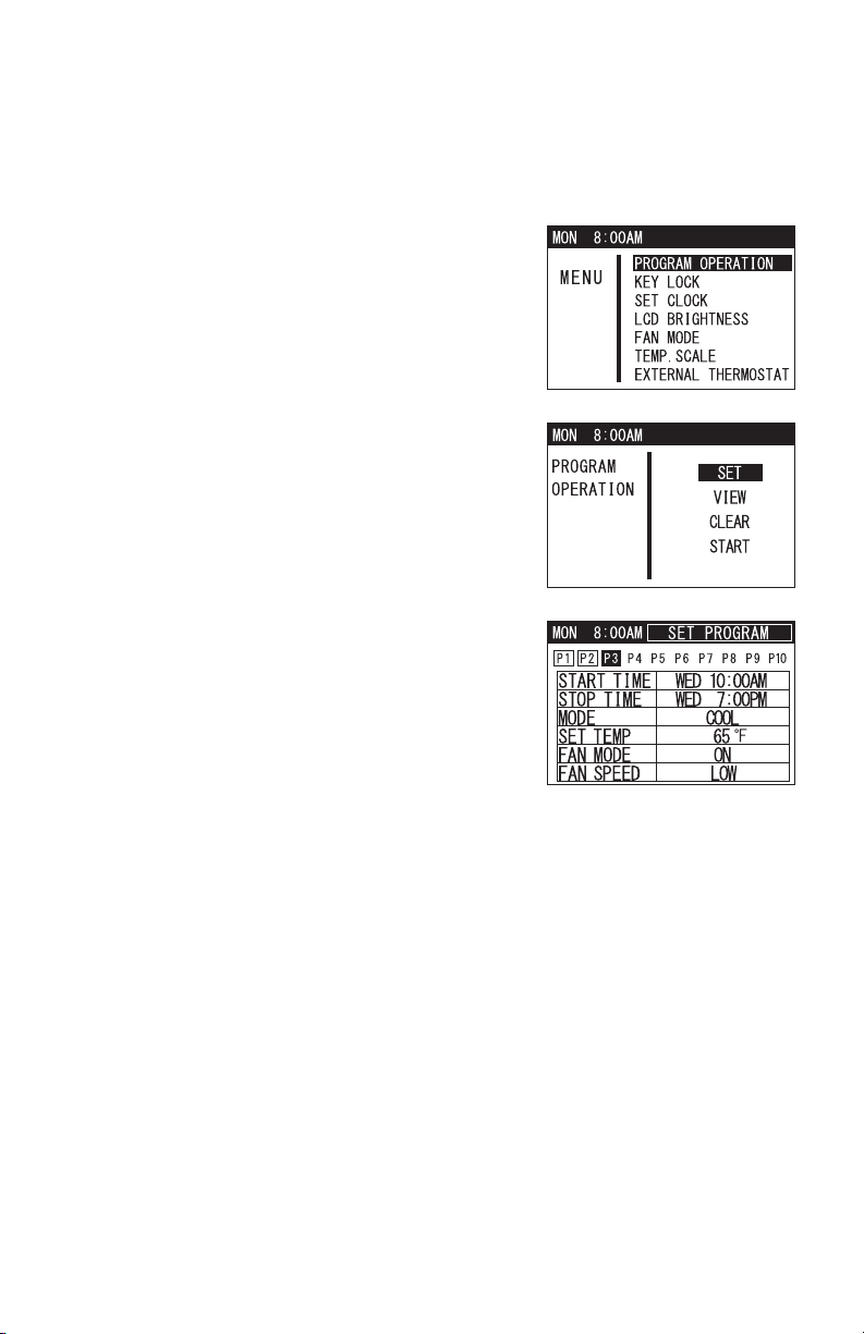
OPERATION (cont.)
Program Operation and Schedule
Setting Program
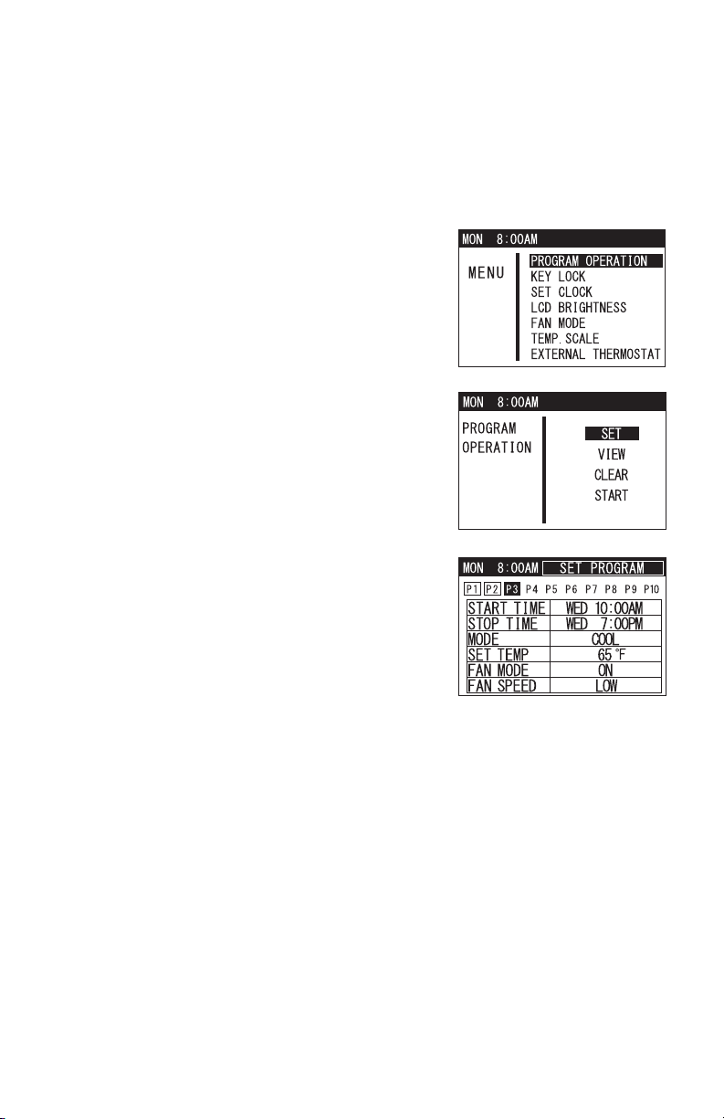
1. Press MENU/ESC button to go to MENU.
Note: If no button is pressed for 1 minute, LCD
displays the previous mode.
2. Use TEMP+ or -TEMP button to select
PROGRAM OPERATION and press ENTER
button to confirm.
3. Select SET under program operation feature
and press ENTER button to confirm.
4. Press ENTER button again to start program
setting. Use TEMP+ or -TEMP button to change
each value (start time ~ fan speed) and press
ENTER button to confirm. Repeat this step.
There are 10 available program slots
(P1 ~ P10). Program slots that have been set
are indicated in a square box.
Note:
• Program counts period from the start time and
day of P1 to the stop time and day of the last
program. Program period can not be overlapped.
• If MENU/ESC button is pressed during start time to fan speed setting, a
program is not completed.
Note: Follow the above steps to edit any preset program slot.
• Use FAN+ or -FAN button to scroll through the preset program slots and
access its content.
5. When setting is completed, press MENU/ESC button to exit from program
setting.
ILL00816-00
ILL00817-00
ILL00818-00
32
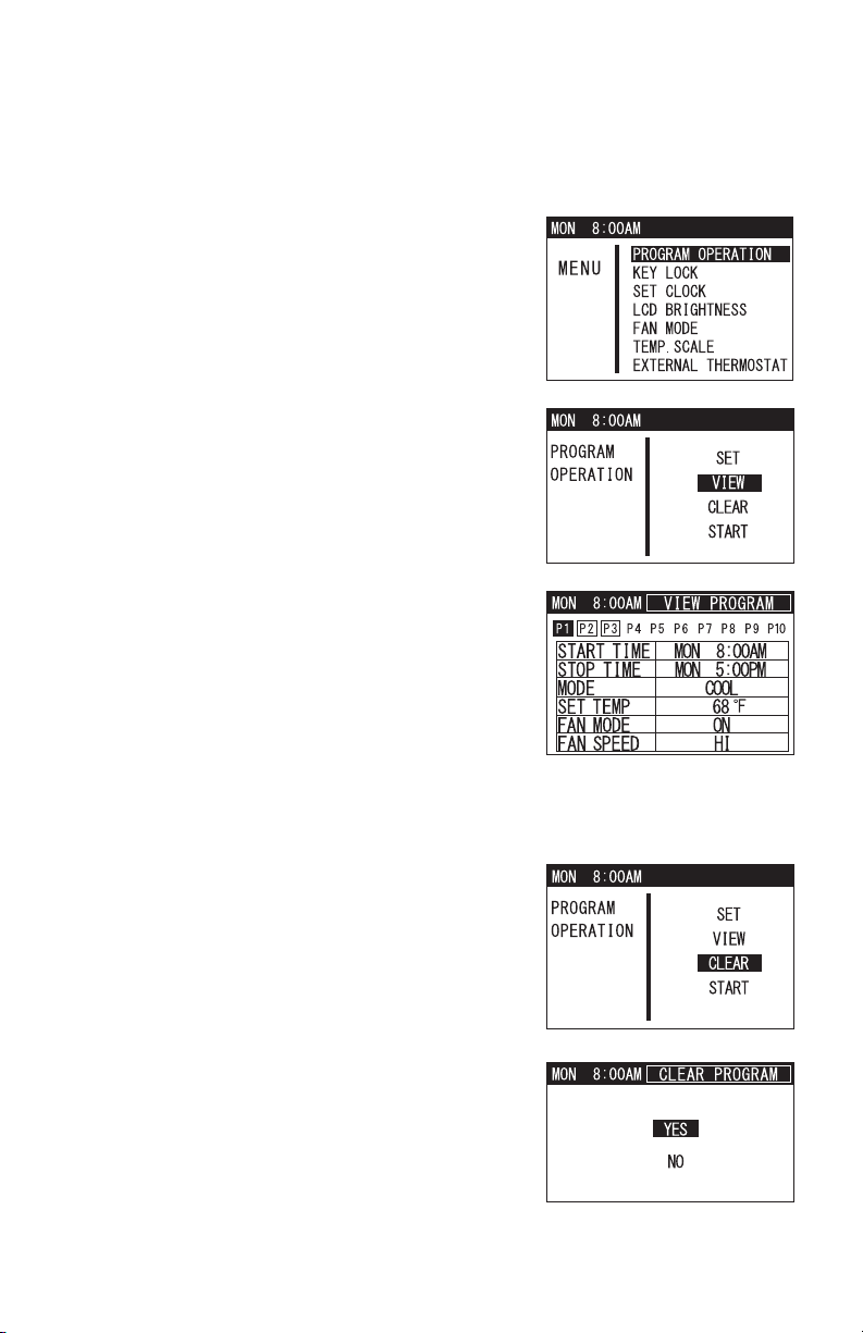
OPERATION (cont.)
Program Operation and Schedule (cont.)
Viewing Program
3. Select VIEW under program operation feature
and press ENTER button to confirm.
4. Use FAN+ or -FAN button to scroll through the
set program slots and view its content.
Clearing All Program Slots
This feature clears the program in all the slots and each program slot content
returns to the default value.
1. Press MENU/ESC button to go to MENU.
Note: If no button is pressed for 1 minute, LCD
displays the previous mode.
2. Use TEMP+ or -TEMP button to select
PROGRAM OPERATION and press ENTER
button to confirm.
1. Select CLEAR under program operation feature
and press ENTER button to confirm.
2. LCD displays a confirmation screen. Use
TEMP+ or -TEMP button to select YES and
press ENTER button to confirm.
ILL00819-00
ILL00816-00
ILL00820-00
ILL00843-00
ILL00821-00
33
OPERATION (cont.)
Program Operation and Schedule (cont.)
Clearing Each Program Slot
This feature clears each set program slot and its content returns to the default
value.
3. Select SET under program operation feature
and press ENTER button to confirm.
4. Use FAN+ or -FAN button to select the set
program slot.
5. Press and hold TEMP+ and -TEMP buttons to
clear the program slot content.
ILL00817-00
ILL00818-00
1. Press MENU/ESC button to go to MENU.
Note: If no button is pressed for 1 minute, LCD
displays the previous mode.
2. Use TEMP+ or -TEMP button to select
PROGRAM OPERATION and press ENTER
button to confirm.
ILL00816-00
34
OPERATION (cont.)
Program Operation and Schedule (cont.)
Starting Program Operation
This feature starts unit operation according to the preset program slots.
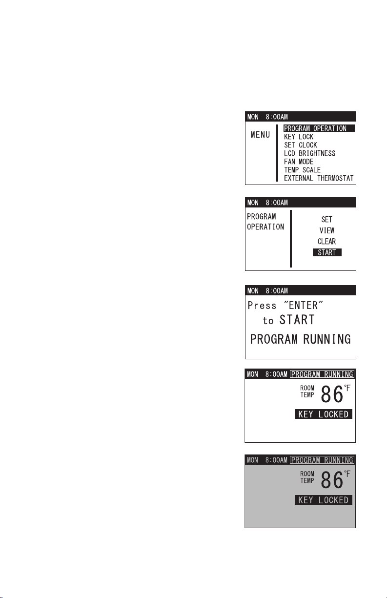
1. Press MENU/ESC button to go to MENU.
Note: If no button is pressed for 1 minute, LCD
displays the previous mode.
2. Use TEMP+ or -TEMP button to select
PROGRAM OPERATION and press ENTER
button to confirm.
3. Select START under program operation feature
and press ENTER button to confirm.
4. LCD displays a confirmation screen as shown
on the right.
Note:
• When program starts running, LCD displays
“PROGRAM RUNNING” and “KEY LOCKED”
with room temperature. LED turns green.
• LCD backlight always stays on during
cooling, heating, or fan only operation when
program is running.
• LCD backlight turns off during standby mode
when program is running. LED stays green.
ILL00816-00
ILL00822-00
ILL00823-00
ILL00824-00
ILL00825-00
35
OPERATION (cont.)
Program Operation and Schedule (cont.)
Stopping Program Operation
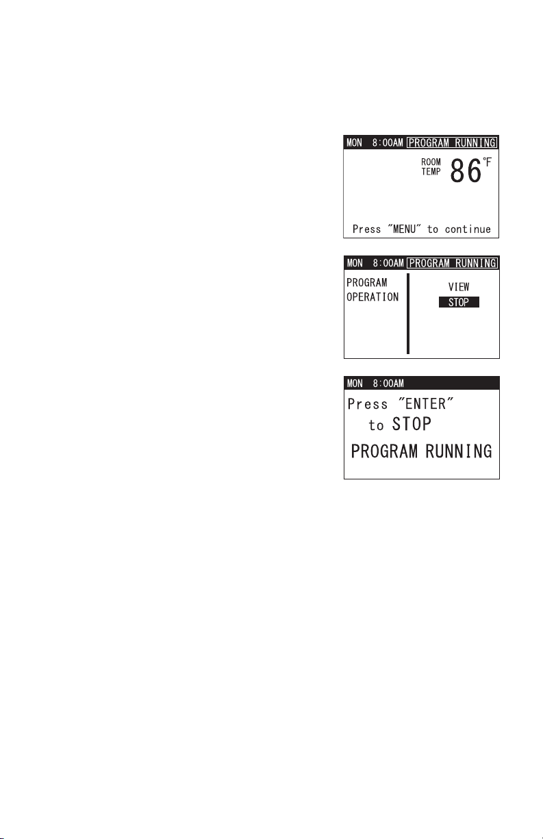
1. Press and hold MENU/ESC button for 5
seconds to unlock other buttons.
After unlocked, if the unit was in standby mode,
LCD only shows room temperature and “Press
MENU to continue”.
Note: If no button is pressed for 1 minute, LCD
screen displays the previous mode.
2. Press MENU/ESC button to go to MENU. Use
TEMP+ or -TEMP button to select STOP and
press ENTER button.
3. LCD displays a confirmation screen as shown
on the right.
ILL00826-00
ILL00827-00
ILL00828-00
36
OPERATION (cont.)
Self-Diagnostic Codes
The Climate Pro 18 has an on-screen self-diagnostic feature that provides a quick
and easy way to troubleshoot issues within the unit. The LCD screen displays self-
diagnostic codes with backlight in orange color to easily distinguish from normal
operation conditions.
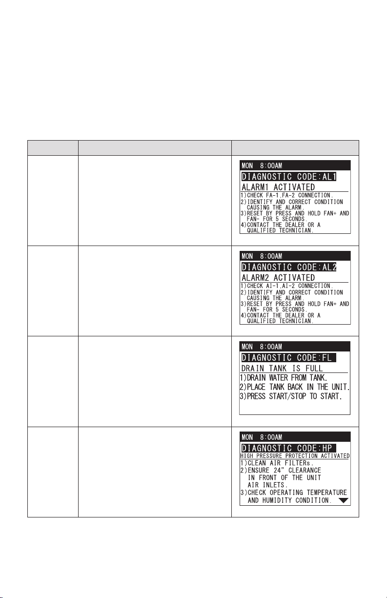
Self-Diagnostic Codes - Table 1
Note: Use TEMP+ or -TEMP button to
scroll down the LCD screen with “
▼ ” mark.
Code Condition LCD Dispaly and Description
AL1 Alarm device 1 is activated.
AL2 Alarm device 2 is activated.
FL Drain tank is full.
HP High pressure protection is activated.
ILL00829-00
ILL00830-00
ILL00831-00
ILL00832-00
37
OPERATION (cont.)
Self-Diagnostic Codes (cont.)
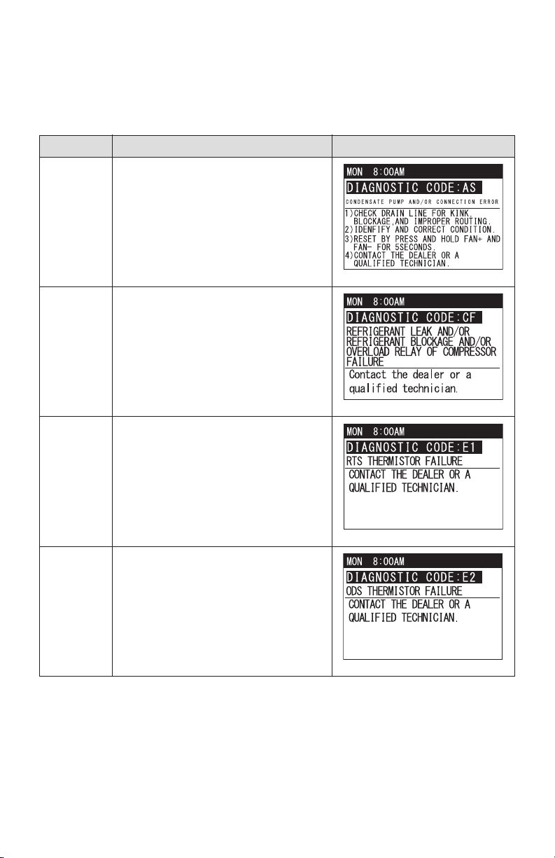
Self-Diagnostic Codes - Table 2
Code Condition LCD Dispaly and Description
AS Optional condensate pump error
CF Cooling or heating function failure
E1 RTS thermistor failure
E2 ODS thermistor failure
ILL00833-00
ILL00834-00
ILL00835-00
ILL00836-00
38
OPERATION (cont.)
Self-Diagnostic Codes (cont.)
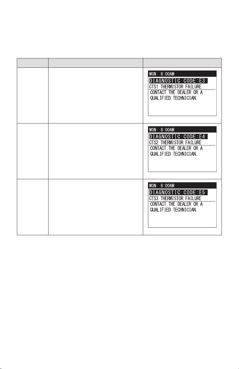
Self-Diagnostic Codes - Table 3
Code Condition LCD Dispaly and Description
E3 CTS1 thermistor failure
E4 CTS2 thermistor failure
E5 CTS3 thermistor failure
ILL00837-00
ILL00838-00
ILL00839-00
39
OPERATION (cont.)
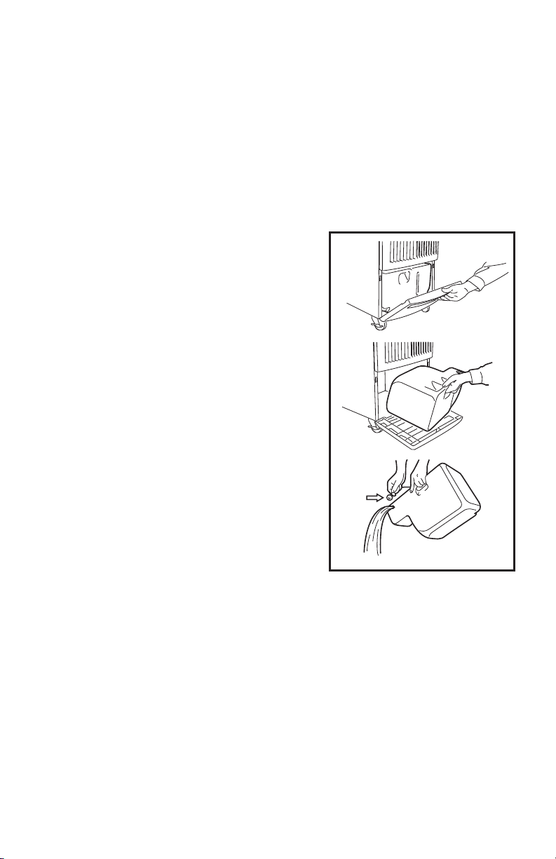
Emptying the Drain Tank
During COOL or HEAT mode, the condensate water accumulates in the dran tank.
When the drain tank becomes full, the LCD displays self-diagnostic code “FL” with
backlight in orange color and the unit turns off automatically.
Note: To empty the drain tank while the unit is in operation, press START/STOP
button to turn the unit off. If a program is running, stop program operation first (see
“Program Operation and Schedule” section).
1. Open the drain tank door.
2. Pull the drain tank from the unit.
3. Remove the cap and empty the drain tank.
4. Replace the cap and return the drain tank to the unit.
5. Close the drain tank door.
6. Press START/STOP button to restart unit operation.
CAP
ILL00063-01
40
OPERATION (cont.)
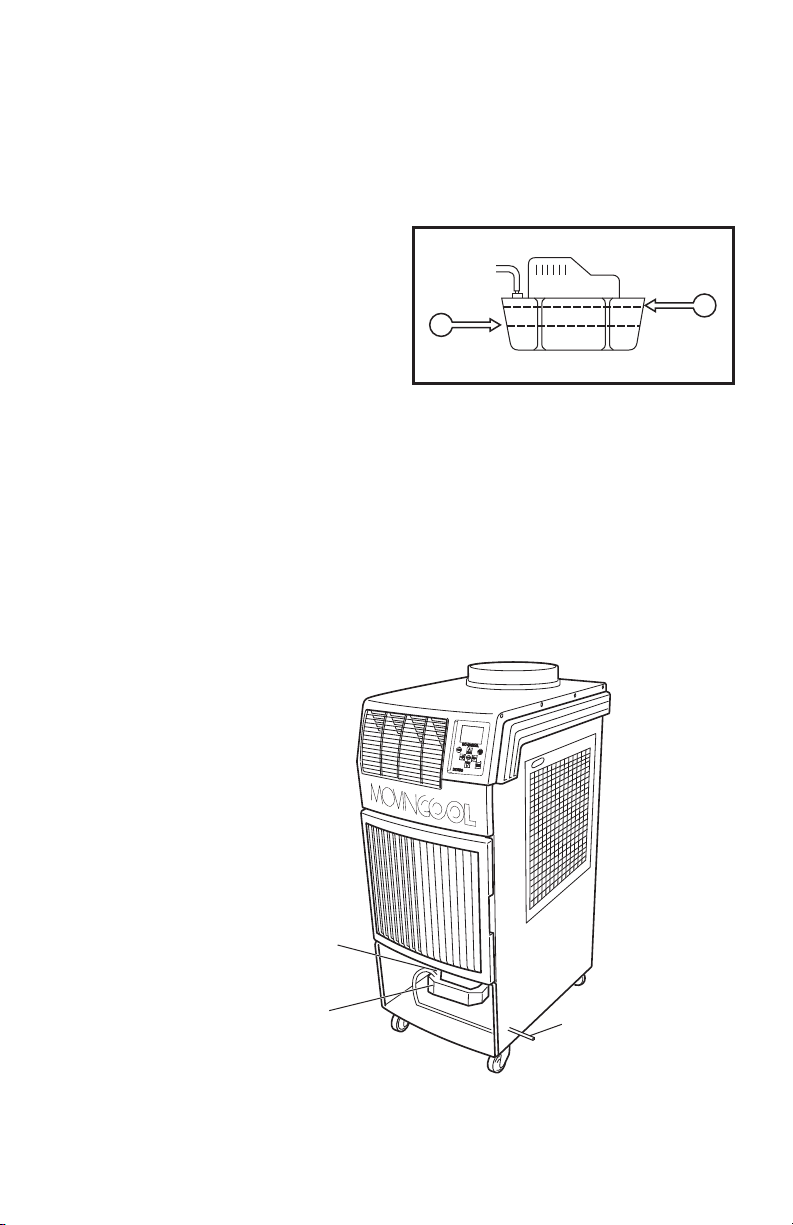
Condensate Pump Kit (Optional Accessory)
The condensate pump kit is available to allow continuous unit operation and
eliminate the need for emptying the drain tank.
When the water collects to level A in the
pump reservoir, the condensate pump
automatically dischages the water.
Note: The compressor does not operate while the condensate pump is
discharging the water out from the reservoir.
When the water level drops below level B, the condensate pump stops, and the
compressor restarts.
Note:
• If for any reason the water level exceeds that of level A in the pump reservoir,
an overflow drain switch stops the unit operation, and the LCD displays “AS”.
• If the fan mode is set to AUTO, the entire unit (including fan operation) turns off
either due to the overflow drain switch or while the condensate pump is
discharging the water.
ILL00064-00
B
A
Condensate Pump
Condensate Pump Reservoir
Discharge Hose
ILL00841-00
41
DAILY MAINTENANCE
Emptying the Drain Tank
See “Emptying the Drain Tank” section.
Air Filter Maintenance
Clean the air filters once a week if the unit is used in a dusty environment.
Note: The dirty air filters can reduce air output resulting in a decreased cooling or
heating capacity.
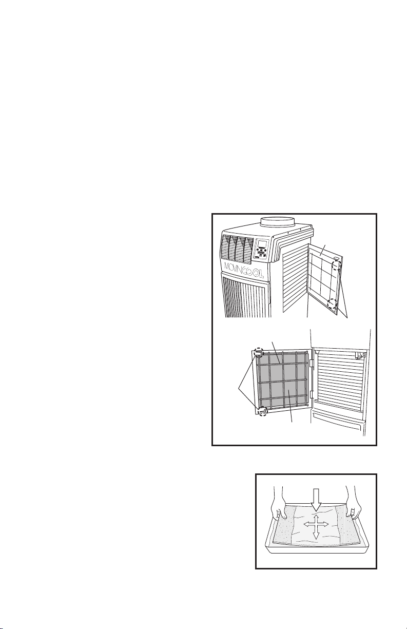
Removing the Air Filters
1. Turn the unit off by pressing START/STOP button. If a program is runnning,
stop program operation first (see “Program Operation and Schedule” section).
2. Open the side panel filter door and
carefully remove the filter by pulling
out the wire frame at two points as
shown in the figure.
3. Open the front panel filter door and
carefully remove the filter from the
wire frame by pulling its clips at two
points shown in the figure.
Cleaning the Air Filters
1. Remove dust from the filters with a vacuum
cleaner, or rinse in cold or lukewarm water. If
the filters are extremely dirty, wash with a
neutral detergent.
2. After the filters are cleaned, rinse with clean
running water, allow to dry, then reinstall.
ILL00842-00
Filter
Wire Frame
Clip
Wire Frame
Filter
Filter
ILL00067-01

42
SEASONAL MAINTENANCE
WARNING:
• To prevent an accident due to electrical shock, perform inspection
and maintenance only after unplugging the power cord.
• Do not use water to clean inside this unit. Exposure to water can
destroy the insulation and electrical components, leading to electric
shock. Interior cleaning must be performed by authorized personnel
only. Consult your MovinCool dealer.
In-Season
In order for the unit to perform properly, conduct thorough inspection and
maintenance on a regular basis.
1. Turn the unit off and unplug the power cord from the power supply outlet.
2. Check the power cord. If dirty, wipe off with a clean dry cloth. If damage or
excess play is found, contact your MovinCool dealer for replacement.
3. Check the air filters and clean if dirty. If damage is found, replace it.
4. Check the drain tank and empty the water. If damage is found, replace it.
5. Check the exterior of the unit. If dirty, clean with a damp cloth or mild
nonabrasive cleaner. If any part requires repair or replacement, contact your
MovinCool dealer or a qualified technician.
Off-Season
1. Operate the unit in FAN ONLY mode for 8 hours.
Note: Operation is necessary to dry out the inside of the unit.
2. Turn the unit off and unplug the power cord from the power supply outlet.
3. Check the power cord. If dirty, wipe off with a clean dry cloth. If damage or
excess play is found, contact your MovinCool dealer for replacement.
4. Check the air filters and clean if dirty. If damage is found, replace it.
5. Check the drain tank and empty the water. If damage is found, replace it.
6. Check the exterior of the unit. If dirty, clean with a damp cloth or mild
nonabrasive cleaner. If any part requires repair or replacement, contact your
MovinCool dealer or a qualified technician.
7. Store the unit for the next season in a clean and dry environment.
43
TROUBLESHOOTING
Check the following conditions before calling your MovinCool dealer or qualified
technician.
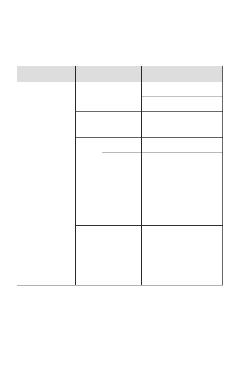
Troubleshooting - Table 1
If conditions persist after the above remedies have been taken, turn the unit off,
unplug the power cord from the power supply outlet, and contact your MovinCool
dealer or a qualified technician.
Condition
Check
Area
Possible
Cause
Remedy
Unit does
not
operate at
all.
No display
on LCD
screen.
Voltage Power failure Check and fix power supply and
connection.
Check and turn the circuit breaker
on.
Ground
fault
protective
breaker
Ground fault
protective
breaker is
tripped.
Reset the ground fault protective
breaker.
LCDI
power
cord
Power cord is
tripped.
Reset the power cord.
Power cord is
damaged.
Replace the power cord.
Fuse on
the relay
board
Fuse is blown. Check a fuse on the relay board. If
a fuse is blown, check power
supply and check for short, then
replace a fuse on the relay board.
LCD
displays
self-
diagnostic
codes.
AL1 Alarm device 1
is activated.
1. Check FA-1, FA-2 connection.
2. Identify and correct condition
causing the alarm.
3. Press and hold FAN+ and -FAN
buttons for 5 seconds to reset.
AL2 Alarm device 2
is activated.
1. Check Al-1, Al-2 connection.
2. Identify and correct condition
causing the alarm.
3. Press and hold FAN+ and -FAN
buttons for 5 seconds to reset.
FL Drain tank is
full.
1. Drain the water from the tank.
2. Place the tank back in the unit.
3. Press START/STOP button to
start.
44
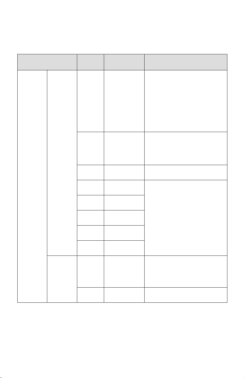
TROUBLESHOOTING (cont.)
If conditions persist after the above remedies have been taken, turn the unit off,
unplug the power cord from the power supply outlet, and contact your MovinCool
dealer or a qualified technician.
Condition
Troubleshooting - Table 2
Check
Area
Possible
Cause
Remedy
Unit does
not
operate at
all.
LCD
displays
self-
diagnostic
codes.
HP High pressure
protection is
activated.
1. Clean the air filters.
2. Ensure 24 inch (610 mm)
clearance in front of the unit air
inlets.
3. Check operating temperature
and humidity condition.
4. Ensure air flow is not blocked
or restricted.
5. Press and hold FAN+ and -FAN
buttons for 5 seconds to reset.
AS Optional
condensate
pump and/or
connection
error
1. Check the drain line for kink,
blockage and improper routing.
2. Identify and correct condition.
3. Press and hold FAN+ and -FAN
buttons for 5 seconds to reset.
CF Refrigerant
problem
Contact your dealer or a qualified
technician.
E1 RTS thermistor
failure
Contact your dealer or a qualified
technician.
E2 ODS thermistor
failure
E3
CTS1 thermistor
failure
E4
CTS2 thermistor
failure
E5
CTS3 thermistor
failure
LCD
displays
notification.
OUTSIDE
OPERATING
RANGE
Unit is
operating
outside
operating
range.
Check product specification for
temperature operating range.
Press any key to exit.
DEFROST
Unit is under
defrost control.
Wait until defrost control is
completed.

45
TROUBLESHOOTING (cont.)
If conditions persist after the above remedies have been taken, turn the unit off,
unplug the power cord from the power supply outlet, and contact your MovinCool
dealer or a qualified technician.
Condition
Troubleshooting - Table 3
Check
Area
Possible
Cause
Remedy
Unit does
not
operate at
all.
LCD
displays
notification.
KEY
LOCKED
Buttons on the
control panel
are locked.
Press and hold MENU/ESC button
for 5 seconds to unlock.
EXTERNAL
THERMOSTAT
ACTIVATED
Status is
changed to
control by an
external
thermostat.
Operate the unit by an external
thermostat.
(See page 30.)
LCD
shows
normal, but
unit does
not start.
Set point
temperature
Room
temperature
reached the set
point
temperature
and the unit is
stopped.
Adjust the set point temperature.
No low fan
speed
during
HEAT
mode
operation.
Fan speed
LO is
automatically
changed to
MID.
Room
tempera-
ture
Room
temperature is
higher than
68 °F (20 °C)
during heating
operation.
Feature to prevent high pressure
protection activation.
No hot air
during
HEAT
mode
operation.
LCD
display
shows
HEAT
mode, but
operates in
COOL
mode.
Fuse (F1) Fuse (F1) is
blown.
Contact your dealer or a qualified
technician.
Reverse
valve
Reverse valve
failure
46
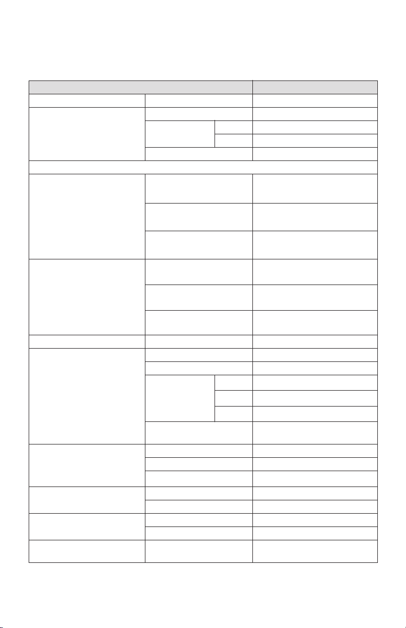
TECHNICAL SPECIFICATIONS
Technical Specifications - Table 1
Item Specifications
elbammargorP latigiDnoitarepOserutaeF cinortcelE
Electrical Characteristics Voltage Requirement 115 V, 1 Phase, 60 Hz
Operating
Voltage Range
Max. 127 V
Min. 104 V
Recommended Fuse Size 20 A
Cooling, Heating Capacity and Power Consumption
Cooling Performance Rating
Condition
(AHAM PAC-1-2009)
Indoor Heat Exchanger:
80 °F (26.7 °C), 50 %RH
Outdoor Heat Exchanger:
80 °F (26.7 °C), 50 %RH
Total Cooling Capacity
14,600 Btu/h (4,270 W)
Power Consumption
1.54 kW
Current Consumption
14.1 A
Heating Performance Rating
Condition
(AHAM RAC-1-2008)
Indoor Heat Exchanger:
70 °F (21.1 °C), 57 %RH
Outdoor Heat Exchanger:
47 °F (8.3 °C), 75 %RH
Heating Capacity 13,700 Btu/h (4,010 W)
Power Consumption 1.61 kW
Current Consumption 14.7 A
yratoR citemreHepyTrosserpmoC
Indoor Heat Exchanger
Outdoor Heat Exchanger
Type of Heat Exchanger Plate Fin
naF lagufirtneCnaF fo epyT
Air Flow High
540 CFM (918 m
3
/h)
Medium
440 CFM (748 m
3
/h)
Low
350 CFM (595 m
3
/h)
Max. External Static
Pressure
0.31 IWG (77 Pa)
Type of Heat Exchanger Plate Fin
naF lagufirtneCnaF fo epyT
Air Flow
700 CFM (1,190 m
3
/h)
A014-RepyTtnaregirfeR
)gk 88.0( bl 49.1tnuomA
Power Cord NEMA Plug Configuration 5-20
12 AWG (3-core) × 10 ft (3.0 m)
ni 05 × 72 × 12H × D ×
Gauge × Length
WnoisnemiD
(533 × 686 × 1,270 mm)
47
TECHNICAL SPECIFICATIONS (cont.)
Technical Specifications - Table 2
• Specifications are subject to change without notice.
Note:
*1: Measured at 3 feet (1.0 m) away from surface of the unit’s front panel.
Item Specifications
)gk 79( bl 412thgieW teN
)L 91( lag 0.5yticapaC knaT niarD
Cooling
Operating Condition Range
Inlet Air
Temperature
Max. 95 °F (35 °C), 60 %RH
Min. 65 °F (18 °C), 50 %RH
Heating
Operating Condition Range
Without duct Max. 80 °F (26.7 °C), 50 %RH
Min. 40 °F (4.4 °C), 50 %RH
With duct Max. 80 °F (26.7 °C), 50 %RH
Min.
Indoor Heat Exchanger:
40 °F (4.4 °C), 50 %RH
Outdoor Heat Exchanger:
24 °F (-4.4 °C), 50 %RH
Maximum Equivalent Duct
Length
)m 6.7( tf 52Indoor Heat Exchanger
Duct
Outdoor Heat Exchanger
Duct
)m 5.03( tf 001
Sound Level
*1
With Outdoor
Heat Exchanger
Duct
High 61 dB (A)
Low 59 dB (A)
Without Outdoor
Heat Exchanger
Duct
High 62 dB (A)
Low 60 dB (A)
WARRANTY STATEMENT
DENSO PRODUCTS AND SERVICES AMERICAS, INC. ("DENSO") warrants its
MOVINCOOL Products only to the extent stated in its official written warranties. Unless
otherwise specifically provided in writing by DENSO, DENSO warrants to the original end-user
that the products shall be free of defects in materials or workmanship and will function in
accordance with DENSO's published specifications under ordinary intended use and service
for a period listed below beginning from the date of purchase on the invoice to the end-user:
Model: Climate Pro 18
Warranty: 3 Years with warranty registration OR
1 Year for unregistered unit.
DENSO shall, at its sole discretion, repair or replace any defective product covered by this
warranty. Such remedy shall be end-user's sole remedy with respect to any particular defect
in the products.
This warranty does not cover defects or malfunctions which result from causes beyond
DENSO's control, including, without limitation, (i) unusual physical or electrical stress; (ii)
accident, neglect, abuse, misuse or other abnormal use; (iii) failure to perform routine
maintenance in accordance with DENSO's recommended procedures; (iv) normal wear and
tear; (v) repairs or attempted repairs by an unauthorized person; (vi) modifications or
alterations to the products; (vii) use with parts or devices not supplied or approved by
DENSO; (viii) improper installation or service; (ix) shipping damage to any units or spare
parts during shipping. This includes and is not limited to compressors and heat exchangers.
This warranty shall extend only to the original end-user and shall be void if any labels or
other identifying marks permanently affixed to products when shipped by DENSO are
removed, altered, defaced or obliterated.
TO THE EXTENT PERMITTED BY LAW, THIS WARRANTY, AS LIMITED HEREIN, SHALL
BE IN LIEU OF AND EXCLUSIVE OF ALL OTHER WARRANTIES, EITHER EXPRESSED
OR IMPLIED, ON THE PART OF DENSO PRODUCTS AND SERVICES AMERICAS, INC.,
OR DENSO CORPORATION, WHETHER ARISING FROM LAW, COURSE OF DEALING,
USAGE OF TRADE, OR OTHERWISE, INCLUDING WITHOUT LIMITATION ANY
IMPLIED WARRANTY OF MERCHANTABILITY OR FITNESS OF A PARTICULAR
PURPOSE OR ANY LIABILITY FOR COMMERCIAL LOSSES BASED UPON
NEGLIGENCE OR MANUFACTURER'S STRICT LIABILITY. EXCEPT AS EXPRESSLY
PROVIDED HEREIN, NEITHER DENSO PRODUCTS AND SERVICES AMERICAS, INC.,
NOR DENSO CORPORATION WILL, IN ANY EVENT, BE LIABLE FOR LOST PROFITS,
COSTS OF PROCESSING, INJURY, GOODWILL, OR ANY OTHER CONSEQUENTIAL
DAMAGES OF ANY KIND ARISING FROM BREACH OF THIS WARRANTY.
PURCHASE DATE:
SERIAL NUMBER:
DENSO PRODUCTS AND SERVICES AMERICAS, INC. reserves the right to make
changes without prior notice. MovinCool®, Office Pro® and SpotCool® are registered
trademarks of DENSO Corporation.


P/N: GX484007-3930 First Issue: September 2014