Loading ...
Loading ...
Loading ...
installation
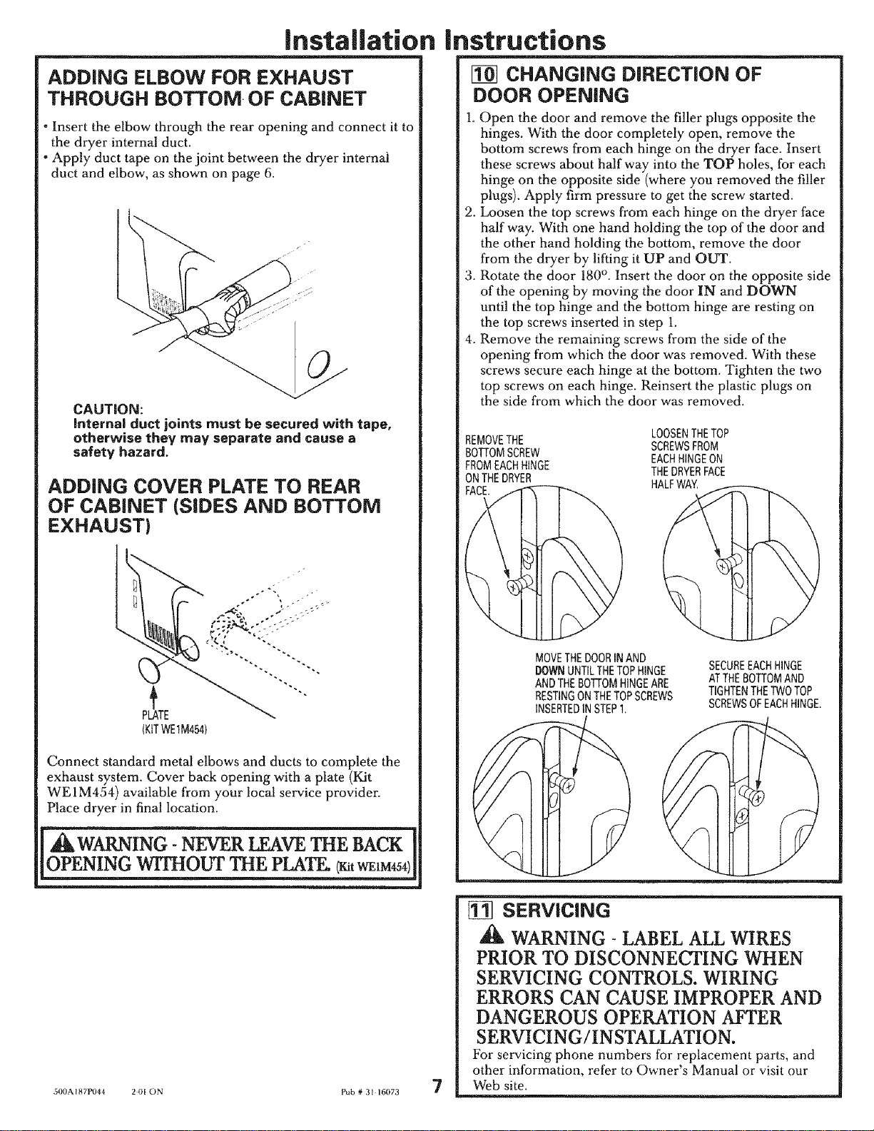
ADDING ELBOW FOR EXHAUST
THROUGH BOTTOM-OF CABINET
- Insert the elbow through the rear opening and connect it to
the dryer internal duct.
*Apply duct tape on the joint between the dryer internal
duct and elbow, as shown on page 6.
CAUTION:
Internal duct joints must be secured with tape,
otherwise they may separate and cause a
safety hazard.
ADDING COVER PLATE TO REAR
OF CABINET (SIDES AND BOTTOM
EXHAUST)
PLATE
(KITWE1M454)
Connect standard metal elbows and ducts to complete the
exhaust system. Cover back opening with a plate (Kit
WE 1M454) available from your local service provider.
Place dryer in final location.
_ILWARNING _EVER LEAVE THE BACK I
|OPENING WI_O_ THE PLATE,_t
500AI87P044 2 01 ON Pub # 31 16073
instructions
CHANGING DiRECTiON OF
DOOR OPENING
1. Open the door and remove the filler plugs opposite the
hinges. With the door completely open, remove the
bottom screws from each hinge on the dryer face• Insert
these screws about half way into the TOP holes, for each
hinge on the opposite side (where you removed the filler
plugs). Apply firm pressure to get the screw started.
2. Loosen the top screws from each hinge on the dryer face
half way. With one hand holding the top of the door and
the other hand holding the bottom, remove the door
from the dryer by lifting it UP and OUT.
3. Rotate the door 180 °. Insert the door on the opposite side
of the opening by moving the door IN and DOWN
until the top hinge and the bottom hinge are resting on
the top screws inserted in step 1.
4. Remove the remaining screws from the side of the
opening from which the door was removed. With these
screws secure each hinge at the bottom. Tighten the two
top screws on each hinge. Reinsert the plastic plugs on
the side from which the door was removed.
REMOVETHE
BOTTOMSCREW
FROMEACHHINGE
ONTHEDRYER
__FACE.
MOVETHEDOORIN AND
DOWNUNTILTHETOPHINGE
ANDTHEBOTTOMHINGEARE
RESTtNGONTHETOPSCREWS
INSERTEDIN STEP1.
LOOSENTHETOP
SCREWSFROM
EACHHINGEON
THEDRYERFACE
HALFWAY.
SECUREEACHHINGE
ATTHEBOTTOMAND
TIGHTENTHETWOTOP
SCREWSOFEACHHINGE.
7
[] SERViCiNG
,_L WARNING- LABEL ALL WIRES
PRIOR TO DISCONNECTING WHEN
SERVICING CONTROLS. WIRING
ERRORS CAN CAUSE IMPROPER AND
DANGEROUS OPERATION AFTER
SERVICING/INSTALLATION.
For servicing phone numbers for replacement parts, and
other information, refer to Owner's Manual or visit our
Web site.
Loading ...