
OPERATION MANUAL
CMW30
Unit Serial Number Range: 0311XXXXCW3 to Present
(From March 2011 to Present)
READ THIS MANUAL CAREFULLY FOR INSTRUCTIONS ON CORRECT
INSTALLATION AND USAGE, AND READ ALL SAFEGUARDS.
SECCIÓN EN ESPAÑOL
SECTION EN FRANÇAIS
AVAILABLE AT WWW.MOVINCOOL.COM
SERIAL NUMBER LOCATION AND IDENTIFICATION
Nameplate Label Position
Nameplate Label
COOLING AMPS. WITH PUMP
COMPR. OUTPUT
REFRIGERANT/TOTAL CHARGE
DESIGN PRESSURE LO/HI
PART NO./WEIGHT
SERIAL NO.
Month
Model
Sequential
Number
Year
▲▲ XXXX ###
© 2013 DENSO PRODUCTS AND SERVICES AMERICAS, INC.
All rights reserved. This book may not be reproduced or copied, in
whole or in part, without the written permission of the publisher.
DENSO PRODUCTS AND SERVICES AMERICAS, INC. reserves the
right to make changes without prior notice. MovinCool®, Office Pro®
and SpotCool® are registered trademarks of DENSO Corporation.

OPERATION MANUAL
CMW30

Table of Contents
SERIAL NUMBER LOCATION AND IDENTIFICATION ................................... 2
FOREWORD ...................................................................................................... 6
Definition of Terms................................................................................ 6
GENERAL WARNINGS & CAUTIONS.............................................................. 6
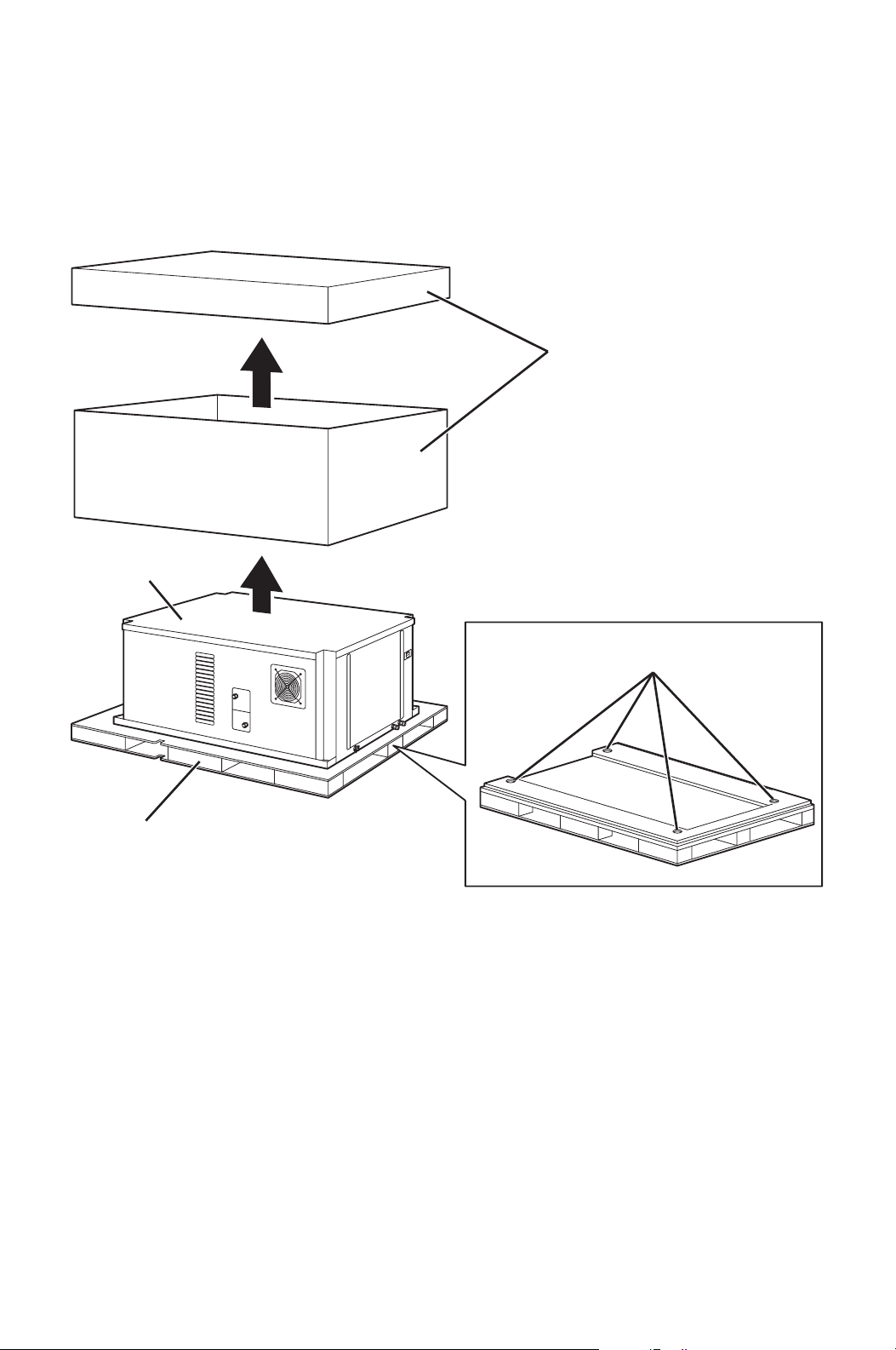
UNPACKING ...................................................................................................... 7
INVENTORY....................................................................................................... 8
INSTALLATION ................................................................................................. 9
Unit Overview ........................................................................................ 9
Unit Dimensions and Clearance Requirement.................................. 10
Mounting CMW30 to Roof Structure.................................................. 11
Water Pipe Connection ....................................................................... 16
Drain Hose Connection....................................................................... 18
Packing Attachment............................................................................ 21
Ducting With Typical Drop Ceiling..................................................... 21
Power Supply and Field Wiring Connection ..................................... 22
DIP Switch Configuration and Setting............................................... 24
Supplied Wall Mounted Controller Connection ................................ 26
Field-Supplied Millivolt Wall Thermostat Connection...................... 31
Warning Signal Connection (Output Signal)..................................... 34
Fire Alarm Connection (Input Signal)................................................ 35
FEATURES OF CMW30 .................................................................................. 37
FEATURES OF WALL MOUNTED CONTROLLER........................................ 37
OPERATION (Wall Mounted Controller ONLY) ............................................ 38
Control Panel ....................................................................................... 38
Standby Mode...................................................................................... 41
Set Clock .............................................................................................. 41
Operate in COOL Mode ....................................................................... 42
Operate in FAN ONLY Mode............................................................... 43
Change Mode....................................................................................... 43
Change Temperature Scale ................................................................ 43
Keypad Lock ........................................................................................ 43
Program Feature.................................................................................. 43
Program Setting .................................................................................. 44
Select Program Sequence Number.................................................... 45
Set Start Time and Operation Mode................................................... 45
Set Stop Time ...................................................................................... 46
Exit Program Mode.............................................................................. 46
View Program ...................................................................................... 46
Edit Program........................................................................................ 47
Delete Program.................................................................................... 47

Run and Stop Program ....................................................................... 47
Program Plan Sheet ............................................................................ 48
SELF-DIAGNOSTIC CODES & BUZZER PATTERN...................................... 49
Self-Diagnostic Codes ........................................................................ 49
Buzzer Pattern ..................................................................................... 49
Table of Self-Diagnostic Codes.......................................................... 50
INSPECTION & MAINTENANCE..................................................................... 51
Cleaning Air Filters ............................................................................. 51
Ground Fault Breaker Testing............................................................ 51
Inspection of Water Lines and Connections..................................... 51
TROUBLESHOOTING ..................................................................................... 52
TECHNICAL SPECIFICATIONS...................................................................... 60

6
FOREWORD
Congratulations on purchasing the MovinCool air conditioner. This manual
explains how to assemble, install and operate the MovinCool CMW30 air
conditioning unit. Please read this operation manual thoroughly to familiarize
yourself with the features of the unit and to ensure years of reliable operation.
You may also find it useful to keep this operation manual on hand for reference.
Components and/or procedures are subject to change without prior notice.
Definition of Terms
WARNING: Describes precautions that should be observed in order
to prevent injury to the user during installation or unit operation.
CAUTION: Describes precautions that should be observed in order
to prevent damage to the unit or its components, which may occur
during installation or unit operation if sufficient care is not taken.
Note: Provides additional information that facilitates installation or unit operation.
GENERAL WARNINGS & CAUTIONS
1. All electrical work should only be performed by qualified electrical personnel.
Repair to electrical components by non-certified technicians may result in
personal injury and/or damage to the unit. All electrical components replaced
must be genuine MovinCool parts, purchased from an authorized reseller.
2. Installation should be conducted by qualified technician only. DENSO and
DENSO affiliate are not responsible for injuries and/or damages caused by
improper installation.
3. Disconnect power before any electrical installation. Beware that some residual
voltage may remain in the unit immediately after the power is disconnected.
4. The power supply for this unit should be a dedicated single outlet circuit with
UL recognized short-circuit and ground-fault protective breaker.
5. Do not place water or any other liquid on the unit. This can cause damage to
the unit and increase the risk of electrical shock.
6. Do not sit or stand on the unit.
7. Do not place hands or any object in the cool air outlet or exhaust duct.
Touching the fan, which is rotating at a high speed, is very hazardous.
8. Do not operate the unit without water connection or without supplied water.
9. Unit connects to water supply and water leakage may cause damage to the
equipment directly under the unit. Do not mount the unit over a sensitive
equipment or a field supplied secondary drain pan may be required under the
unit.
8
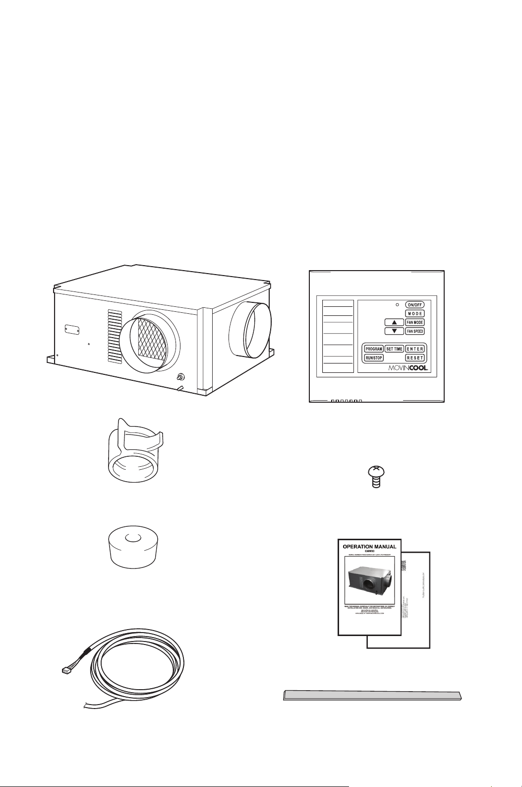
INVENTORY
After unpacking your MovinCool unit, please check to make sure you have the
following items:
1. CMW30 MovinCool Unit (1)
2. Operation Manual/Product
Registration (1)
3. Clip (1)
4. Packing (1)
5. Vibration Isolator (4)
6. Wall Mounted Controller (1)
7. Shield Wire (1)
8. Screw (4)
Note: If any of these items were not included in the box or appear damaged,
please contact your MovinCool reseller for replacement.
CMW30 UNIT WALL MOUNTED CONTROLLER
SCREW FOR WALL
MOUNTED CONTROLLER
OPERATION MANUAL /
PRODUCT REGISTRATION
CLIP
VIBRATION ISOLATOR
PACKING (1.8 × 43.9 × 0.2 in)
SHIELD WIRE FOR WALL
MOUNTED CONTROLLER (12 ft)
ILL00252-00
9
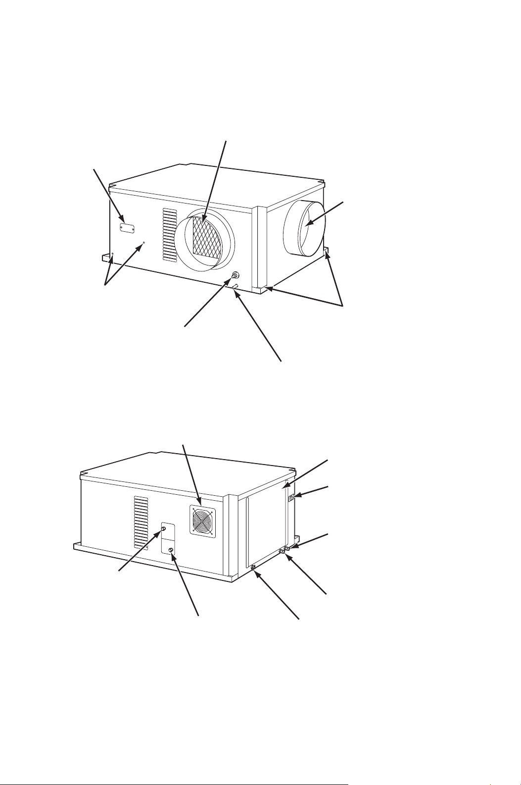
INSTALLATION
Unit Overview
ILL00253-00
COOL AIR EXHAUST
(12.0 in. DIA. FLANGE)
DRAIN PIPE FOR PUMP
EVAPORATOR (ROOM)
AIR INTAKE
(14.0 in. DIA. FLANGE)
MOUNTING HOLES
CONDENSATE PAN DRAIN
FOR GRAVITATIONAL DRAIN/MAINTENANCE
CONNECTION FOR
OPTIONAL
CONDENSATE PUMP
FIXING POSITION FOR
OPTIONAL
CONDENSATE PUMP
AC FAN MOTOR
SERVICE PANEL
WALL MOUNTED
CONTROLLER/MILLIVOLT
WALL THERMOSTAT
WIRE INLET
POWER CORD INLET
WATER INLET
(3/4 in NPT FEMALE)
WATER OUTLET
(3/4 in NPT FEMALE)
SIGNAL WIRE INLET
STOP SWITCH
ILL00254-00
10
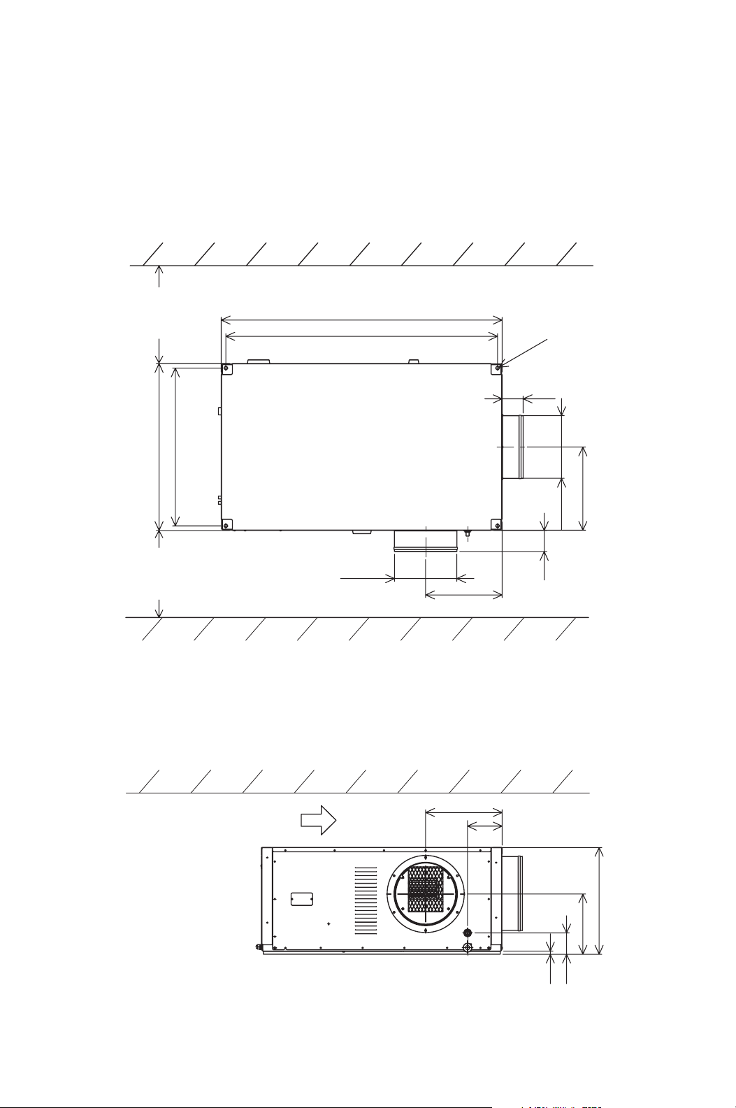
INSTALLATION (cont.)
Unit Dimensions and Clearance Requirement
43.7
45.4
All dimensions are in inches.
Unit Weight: 236 lb (107 kg)
29.8
DIA. 0.6
3.9
16.0
DIA. 14.0
DIA. 12.0
14.4
3.9
31.5
WALL
Minimum
clearance
5.0 inch
from wall
Minimum
clearance
20.0 inch
from wall
CEILING
Top of the unit should not contact
any building structure or object.
WALL
0.6
10.7
20.0
14.4
6.5
4.0
ILL00255-00
11
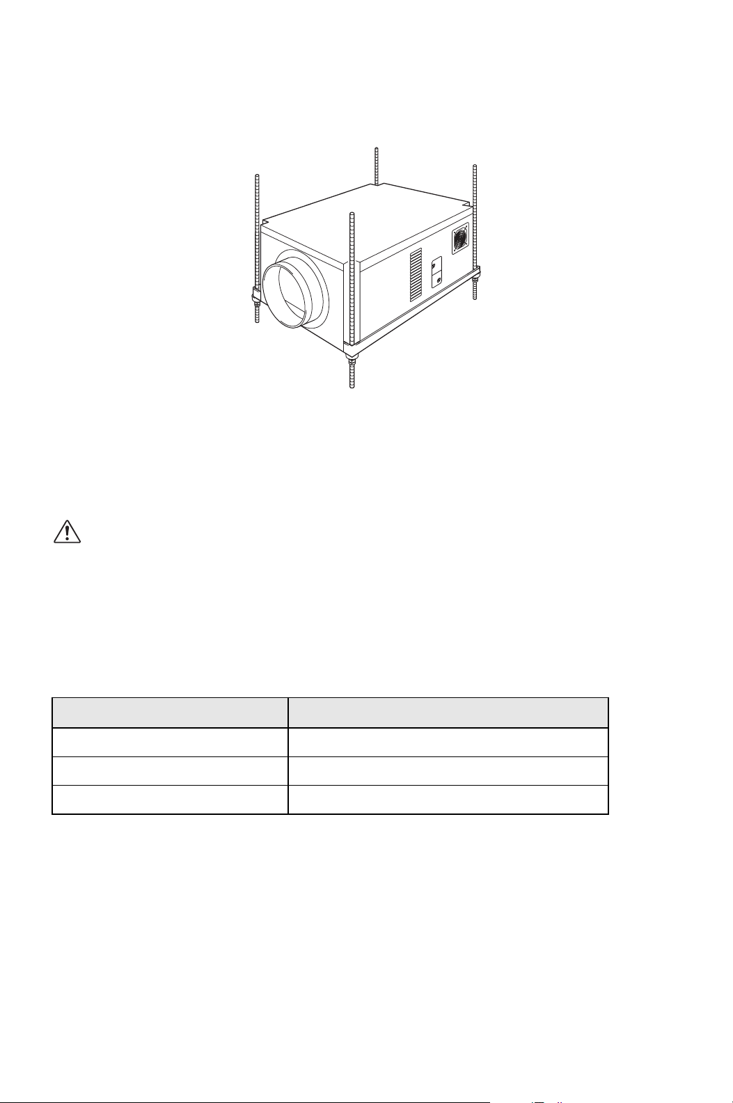
INSTALLATION (cont.)
Mounting CMW30 to Roof Structure
Be sure to securely anchor the top ends of the suspension rods. Make sure all nuts
are tight. Be sure to follow all applicable codes.
The unit is usually mounted above the ceiling and must be securely mounted to
the roof structure. The ceiling support of the existing building may require
reinforcements.
WARNING: Make sure the supporting roof structure is capable of
supporting the weight of the unit, mounting hardware and the
accessories. Roof structure should be able to support four times of
total weight or more. Unit weight is 236 lb (107 kg).
The recommended clearance between ceiling grids and building structural
member is the unit height plus 3.0 inch (76 mm).
All mounting hardware except vibration isolators is field supplied.
Use the following hardware.
Hardware (Quantity) Size
Threaded suspension rod (4) 1/2 in (Min. 236 lb (107 kg) load capability)
Nut (12) 1/2 in
Washer (4) 1/2 in
ILL00256-00
12
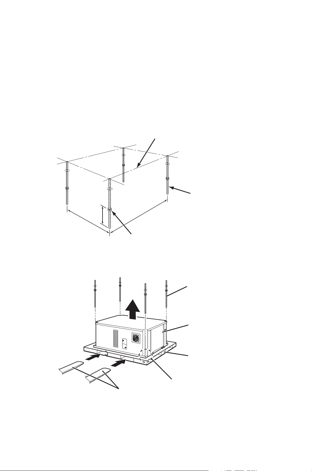
INSTALLATION (cont.)
Mounting CMW30 to Roof Structure (cont.)
Example of Mounting with Pallet
1. Install four (4) suspension rods by suspending them from suitable building
structure members. Locate the rods so that they will align with four mounting
holes that are part of the unit base. Make sure to securely anchor the top ends
of the suspension rods and tighten all nuts.
2. Insert four (4) nuts (top) to the suspension rods before mounting the unit (12.0
inch minimum height from the bottom end of the suspension rods).
3. Locate the rods so that they will align with four mounting holes. Enter the lifts
into pallet openings. Slowly lift up the unit with the pallet.
12.0 in
Min.
29.8 in
43.7 in
THREADED
SUSPENSION ROD
ROOF STRUCTURE
NUT (top)
ILL00257-00
LIFTS
UNIT
PALLET
SUSPENSION ROD
MOUNTING HOLE
ILL00258-00
13
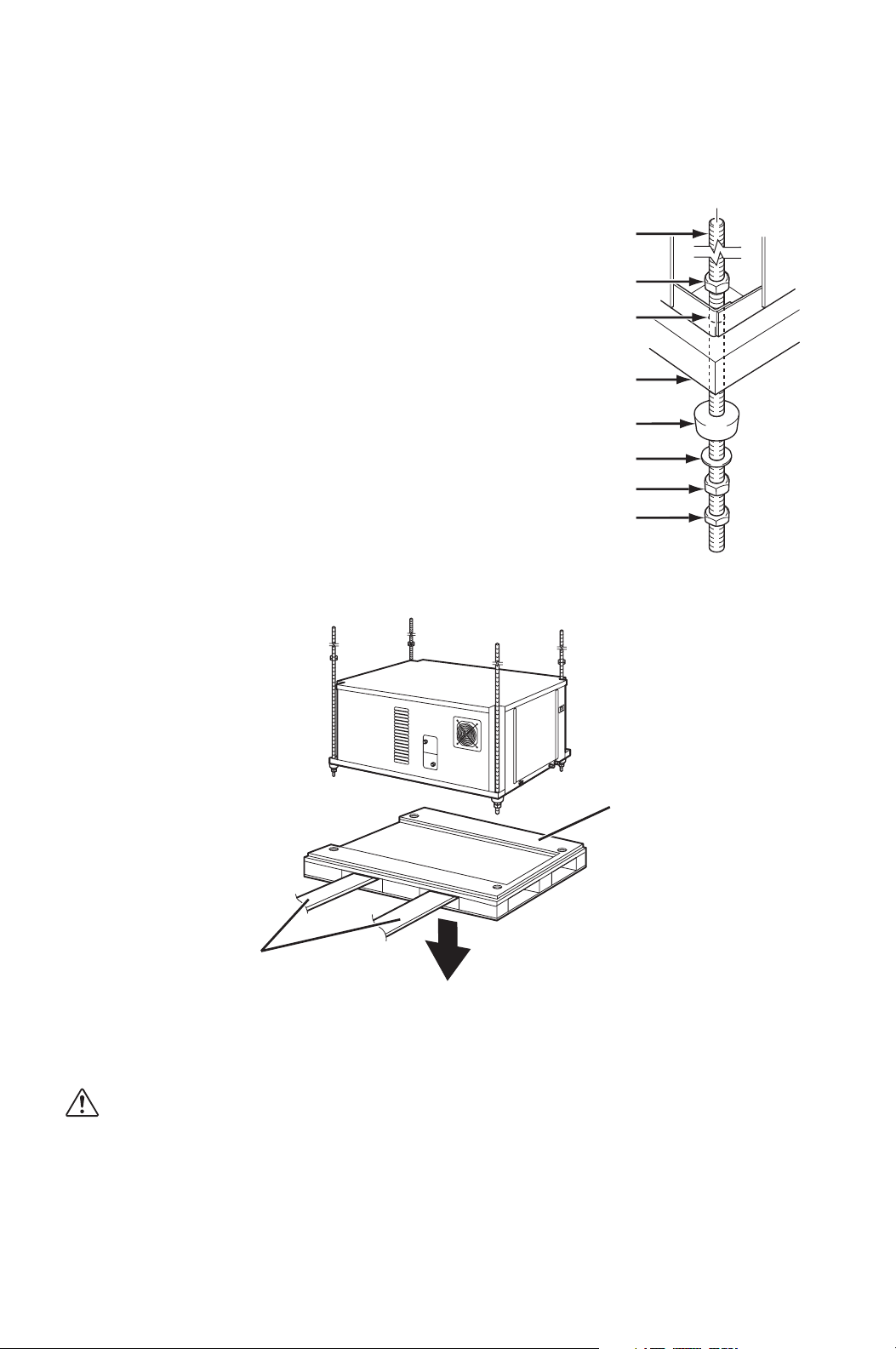
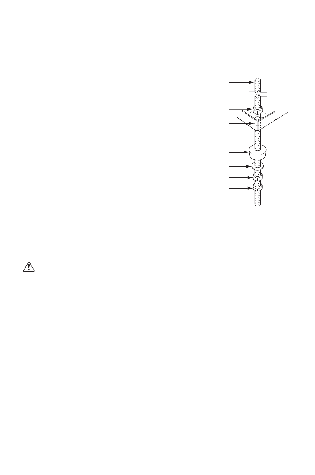
INSTALLATION (cont.)
Mounting CMW30 to Roof Structure (cont.)
Example of Mounting with Pallet (cont.)
4. Insert the suspension rods
through the mounting holes of
unit and pallet. Then install
vibration isolators, washers,
nuts (middle) and jam nut
(bottom) to be same level for
all four mounting positions.
5. Slowly lower the pallet with the lifts.
6. Make sure the unit is level.
Level must be less than 2° incline.
If the unit is not level, align the nut (middle) to level.
CAUTION: If level is more than 2° incline, condensation water
leakage may occur.
7. Tighten the jam nut (bottom).
Tightening torque for jam nut: Approx. 3.02 ft•lbf (4.1 N•m)
8. Tighten the nut (top) by hand until it is secured against the base frame.
SUSPENSION ROD
NUT (top)
MOUNTING HOLE
VIBRATION ISOLATOR
PALLET
WASHER
NUT (middle)
JAM NUT (bottom)
ILL00259-00
LIFTS
PALLET
ILL00260-00
14
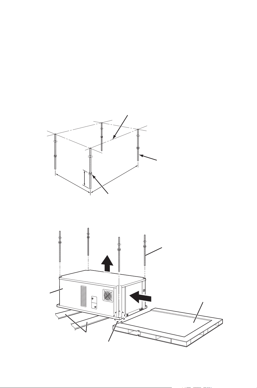
INSTALLATION (cont.)
Mounting CMW30 to Roof Structure (cont.)
Example of Mounting without Pallet
1. Install four (4) suspension rods by suspending them from suitable building
structure members. Locate the rods so that they will align with four mounting
holes that are part of the unit base. Make sure to securely anchor the top ends
of the suspension rods and tighten all nuts.
2. Insert four (4) nuts (top) to the suspension rods before mounting the unit (12.0
inch minimum height from the bottom end of the suspension rods).
3. Locate the rods so that they will align with four mounting holes. Slide the unit
from the pallet onto the lifts. Slowly lift up the unit.
12.0 in
Min.
29.8 in
43.7 in
THREADED
SUSPENSION ROD
ROOF STRUCTURE
NUT (top)
ILL00257-00
UNIT
PALLET
LIFTS
MOUNTING HOLE
SUSPENSION ROD
ILL00261-00
15
INSTALLATION (cont.)
Mounting CMW30 to Roof Structure (cont.)
Example of Mounting without Pallet (cont.)
4. Insert the suspension rods
through the mounting holes of
the unit. Then install vibration
isolators, washers, nuts
(middle) and jam nut (bottom) to
be same level for all four
mounting positions.
5. Slowly lower the lifts.
6. Make sure the unit is level. Level must be less than 2° incline. If the unit is
not level, align the nut (middle) to level.
CAUTION: If level is more than 2° incline, condensation water
leakage may occur.
7. Tighten the jam nut (bottom).
Tightening torque for jam nut: Approx. 3.02 ft•lbf (4.1 N•m)
8. Tighten the nut (top) by hand until it is secured against the base frame.
SUSPENSION ROD
NUT (top)
MOUNTING HOLE
VIBRATION ISOLATOR
WASHER
NUT (middle)
JAM NUT (bottom)
ILL00356-00
16
INSTALLATION (cont.)
Water Pipe Connection
WARNING: Before wiring the unit, connect the water line to the unit.
To avoid electrical shock, make sure that there is no water splashed
onto the electrical box.
CMW30 unit is equipped with two female 3/4 inch NPT (National Pipe Thread)
connectors for water connections. Two water pipes with 3/4 inch NPT Male
connectors and proper insulators are required for field installation.
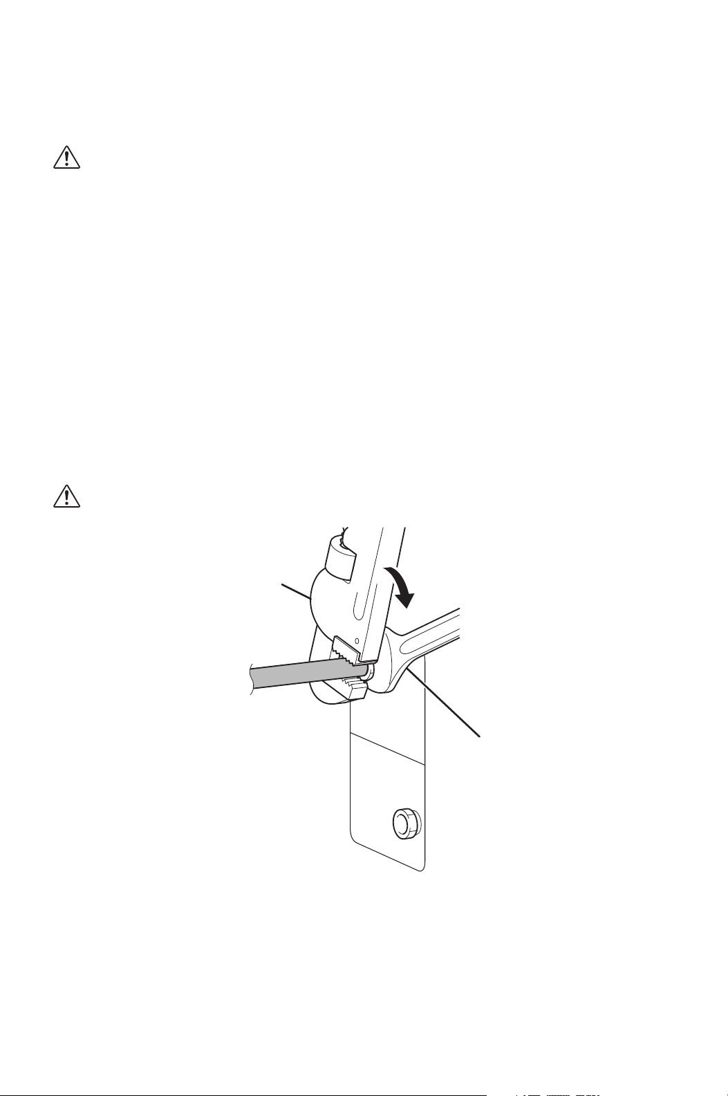
Connecting Water Pipes
1. Remove the caps from the NPT connectors on the rear side of the unit.
Note: Small residues of water may drip from the NPT connectors when the caps
are first removed.
2. Apply teflon tape to the NPT male connectors.
3. Connect the threaded water pipes or pipes with the NPT male connectors to
the NPT female connectors on the unit. Hold the wrench A tightly so that the
pipe on the unit is not deformed, then tighten the connector with the wrench B.
CAUTION: Use proper size wrenches.
WRENCH A
WRENCH B
ILL00332-00
17
INSTALLATION (cont.)
Water Pipe Connection (cont.)
Connecting Water Pipes (cont.)
4. Make sure the water inlet and outlet of the unit and water source are
connected, and there is no water leakage.
CAUTION: Supply water pressure limitation is maximum 150 psi
(1,034 kPa). Do not use the unit with water which contains a high
corrosive factor.
5. Attach the insulators to the water pipes and connectors to prevent
condensation.
CAUTION: If the insulators are not attached properly, condensation
may occur.
Note:
1. Service shut-off valves and drain plugs are recommended to be installed at the
water supply and return lines for routine field service or emergency service.
The drain plugs are used to drain the remaining water in the system. The shut-
off valves and drain plugs should have a minimum pressure rating of 150 psi
(1,034 kPa). The drain plugs should be connected between the shut-off valves
and the unit.
2. When supply water quality is poor, filters that can be easily serviced should be
placed in the water supply line.
ILL00333-00
18
INSTALLATION (cont.)
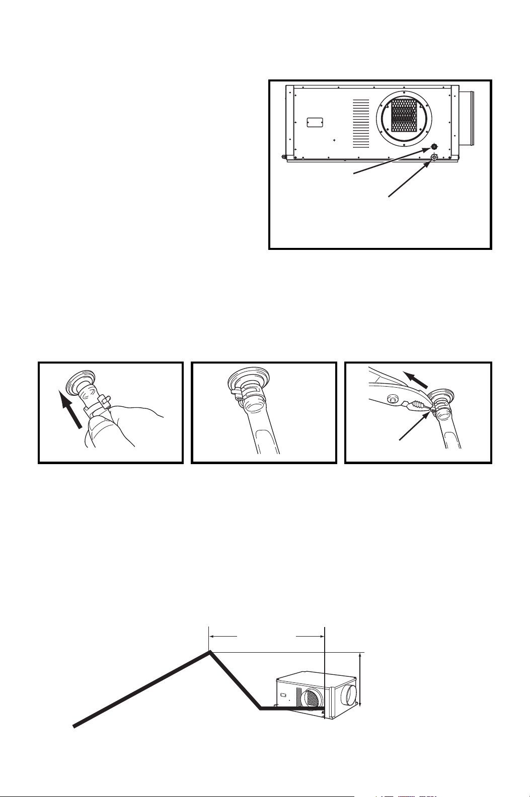
Drain Hose Connection
The CMW30 is equipped with an
internal condensation removal pump
with maximum head lift of 4 feet (1.2 m).
1. Use the provided 1/2 inch (13 mm)
male connection on the unit for the
evaporator coil condensate drain.
The drain line must be located so it
will not be exposed to freezing
temperatures. The drain should be
the full size of the drain connection.
(Connect the drain hose to the
condensation drain or the janitor closet.)
2. PVC tubing (1/2 inch (13 mm) for ID, 5/8 inch (16 mm) for OD) is required for
the drain. Insulate the drain hose. Condensation may occur during humid
conditions.
Note: PVC tubing and insulation material are field supplied.
Note: Do not use more than 4 feet (1.2 m) of drain hose vertically. This is maximum
lift of the condensation pump.
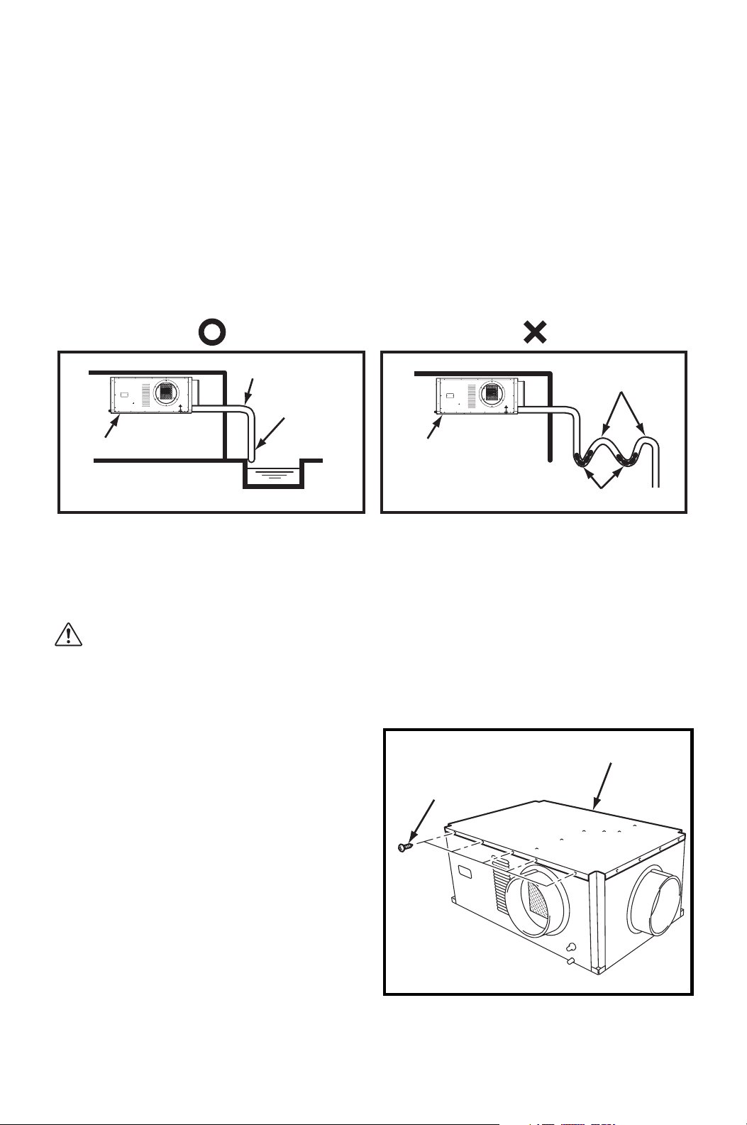
3. To insure proper drainage, locate the drain hose to the highest vertical position,
no more than 4 feet (1.2 m) high, and run the hose to the drain on a downward
slope at a minimum rate of 1/4 inch (6 mm) per foot.
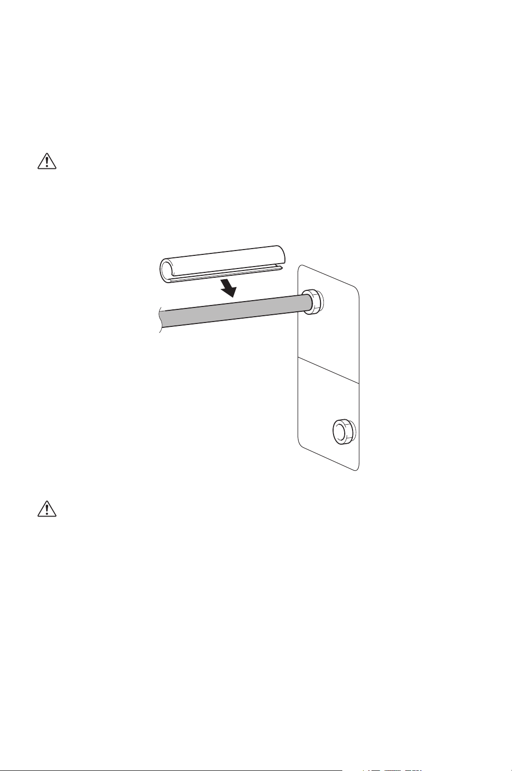
1. Plug in the 1/2 inch (13
mm) drain hose with the
supplied clip into the drain
pipe. Make sure the hose
is all the way in and flush
with the grommet.
2. Position the clip to the top
of the drain pipe near the
unit as shown.
3. Pull out the stopper and
secure hose. Make sure
there are no kinks or bends.
When using the gravity
drain, make sure the hose
is connected as a decline.
DRAIN PIPE
CONDENSATE PAN DRAIN
FOR GRAVITATIONAL
DRAIN/MAINTENANCE
ILL00262-00
ILL00263-00 ILL00264-00
STOPPER
ILL00265-00
MAX. 3 ft
(0.9 m)
MAX. 4 ft (1.2 m)
1/4 in (6 mm)
PER FOOT
OR MORE
ILL00266-00
19
INSTALLATION (cont.)
Drain Hose Connection (cont.)
4. Check the following items.
• No kinks or bends on the drain hose
• No trap in the drain hose
• The end of the drain hose should be higher than the water level at the drain
• No dripping from the drain hose at the clamping area
• When uninstalling the unit, empty the drain pan by draining out the water
through the condensate pan drain pipe.
For the gravitational drain, power connection to the internal condensation removal
pump must be disconnected. Follow the procedures shown below.
CAUTION: The condensate water will drain out from the drain pipe
of the condensate pan if the internal condensation removal pump
connector is not disconnected.
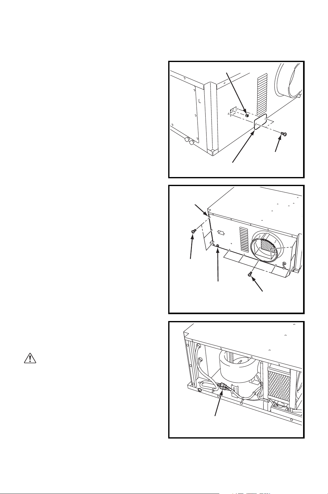
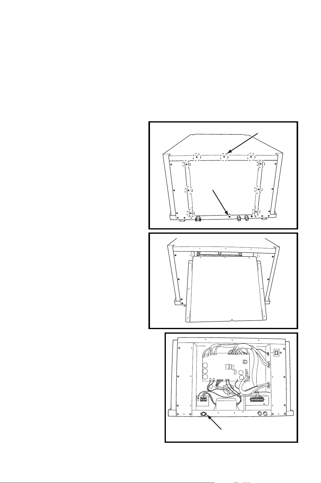
1. Disconnect power.
2. Remove five (5) screws from the top
panel.
UNIT
SLOPE
ABOVE
DRAIN
WATER
NO TRAP
TO DRAIN HOSE
UNIT
NO TRAP
NO POOL
ILL00267-00
SCREWS (5)
TOP PANEL
ILL00344-00
20
INSTALLATION (cont.)
Drain Hose Connection (cont.)
3. Remove the cover plate by removing
two (2) screws. Remove the jumper
plug from the mating connector.
4. Loosen the bottom screw (1).
Remove the front panel by removing
fifteen (15) screws.
5. Disconnect the 2-pin connector
(yellow wire) of the internal
condensation removal pump.
WARNING: Make sure the
connectors are sealed and
secured to prevent electrical
shock or short circuit.
SCREWS (2)
JUMPER PLUG
COVER PLATE
ILL00345-00
SCREWS (12)
SCREWS (3)
FRONT
PANEL
BOTTOM SCREW (1)
ILL00346-00
2-PIN CONNECTOR
(YELLOW WIRE)
ILL00347-00
21
INSTALLATION (cont.)
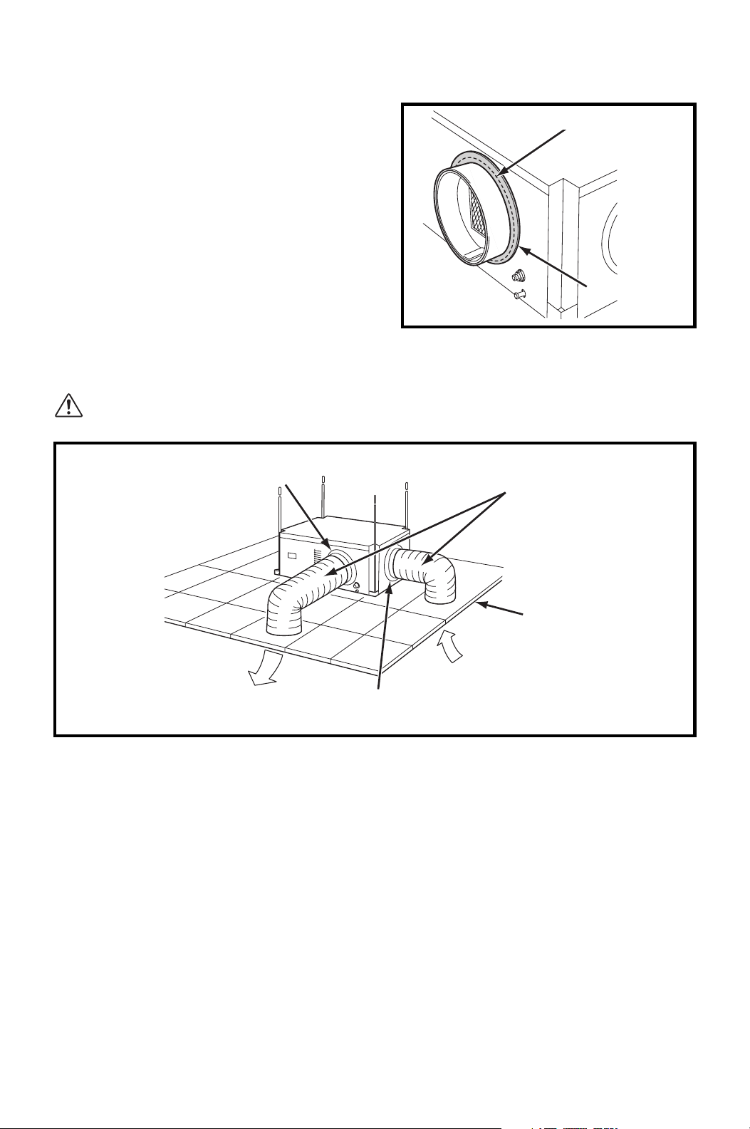
Packing Attachment
Apply the provided packing to the cool air
exhaust to prevent condensation in high
humidity environments.
Remove the liner on the packing and
attach the packing to cover the edge of the
duct flange to avoid cool air leaking
through the gap.
Ducting With Typical Drop Ceiling
All hardware is field supplied.
CAUTION: Do not operate the unit without the filter installed on the
return air grill.
1. Use 12 inch and 14 inch diameter insulated ducts with low friction and air
resistance. The duct should be bent in a large radius. If the bending radius is
less than 15.0 inch (381 mm), then use vanes or guides to reduce air
resistance.
2. Make sure the ducts are secured in order to absorb vibration from the unit.
Avoid sharp bending on the duct and have air ducts travel in a straight line for
improved performance.
Field supplied hardware requires:
• Insulated 12 inch diameter flexible duct
• Insulated 14 inch diameter flexible duct
• Return air grill with 14 inch flange and filter for the room air intake
• Diffuser with 12 inch flange for the cool air outlet
Refer to the maximum static pressure of “Technical Specifications” on
page 60.
PACKING
EDGE of DUCT FLANGE
ILL00268-00
FLANGE
(12 in DIA.)
FLANGE
(14 in DIA.)
COOL AIR SUPPLY
(EVAPORATOR)
ROOM AIR
INTAKE
RETURN AIR
GRILL WITH
FILTER REQUIRED
INSULATED
FLEXIBLE DUCT
ILL00269-00
22
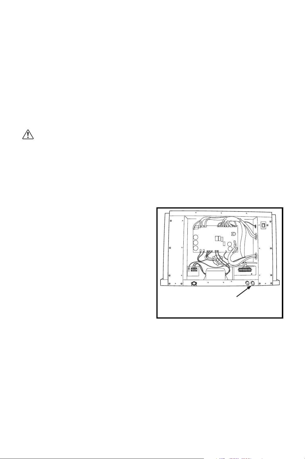
INSTALLATION (cont.)
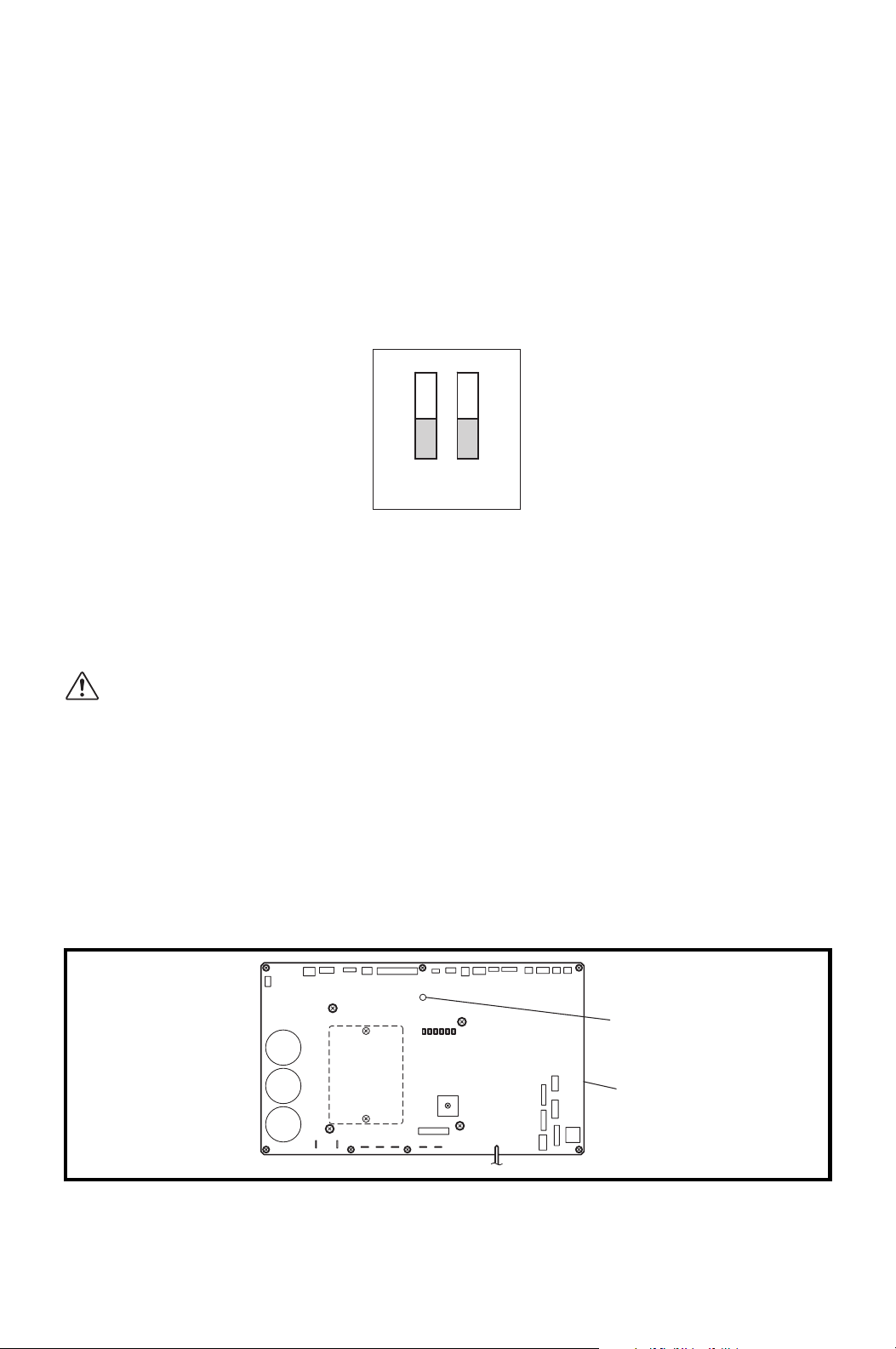
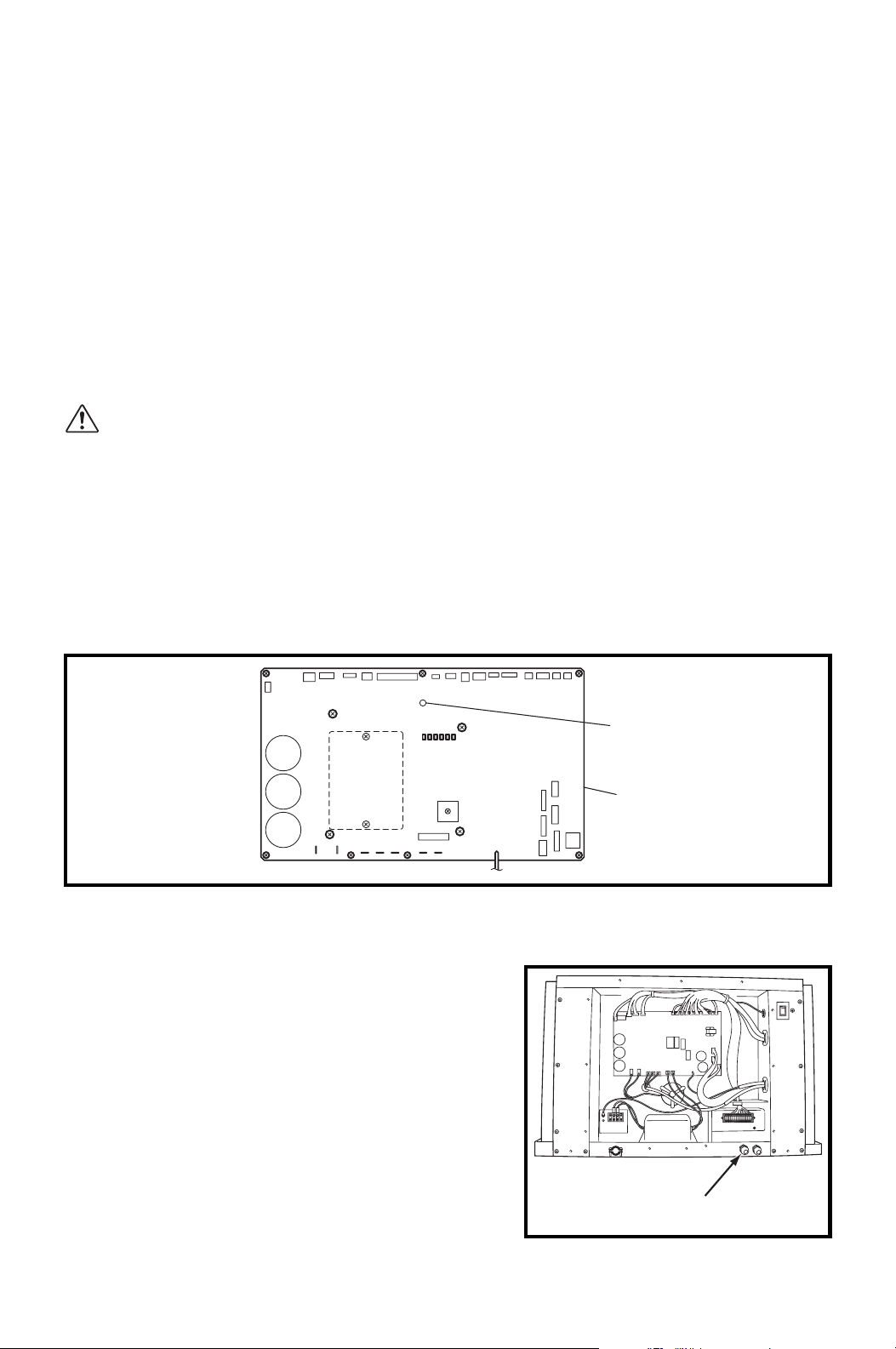
Power Supply and Field Wiring Connection
WARNING:
1. All electrical work should only be performed by qualified personnel.
Repair to electrical components by non-certified technicians may
result in personal injury and/or damage to the unit.
2. Disconnect power before any electrical installation. Beware that
some residual voltage may remain in the unit immediately after the
power is disconnected.
3. Do not touch the relay board of the unit until the green LED7 is
turned off. Failure to follow this warning may lead to electrical
shock.
Power Supply
• The unit requires a single-phase, 208/230 V, 60 Hz power supply to operate.
• The power supply should be a dedicated single outlet circuit with UL recognized
short-circuit and ground-fault protective breaker with a fuse size of 20 A maximum.
• Securely tighten each terminal.
CAUTION: Use a specified 20 A fuse. Do not use wiring, copper wire
or soldering instead of the fuse. The use of non-specified fuses can
cause machine failure or fire.
LED 7
ILL00697-00
16
Relay Board
CIRCUIT BREAKER WITH
GROUND-FAULT PROTECTIVE
FUSE 20 A MAX.
RTG
RTG
TERMINAL BLOCK OF UNIT
GROUND TERMINAL
23
INSTALLATION (cont.)
Power Supply and Field Wiring Connection (cont.)
Field Wiring Connection
The following are recommended wire sizes and electrical ratings:
• Cord Type: SJT (3 wires) or equivalent
• Wire Gauge: 12 AWG
• Voltage Rating: 300 V minimum
• Heat Resistance: 221 °F (105 °C)
1. Loosen the bottom screw (1).
2. Remove nine (9) screws from
the service panel on left side of
the unit.
Tightening torque for screw:
Approx. 1.10 ft•lbf (1.5 N•m)
3. Remove the service panel.
4. Route power cord wires through
the power cord inlet located below
service panel.
SCREW (9)
BOTTOM
SCREW
ILL00272-00
ILL00273-00
POWER CORD INLET
ILL00289-00
24
INSTALLATION (cont.)
Power Supply and Field Wiring Connection (cont.)
Field Wiring Connection (cont.)
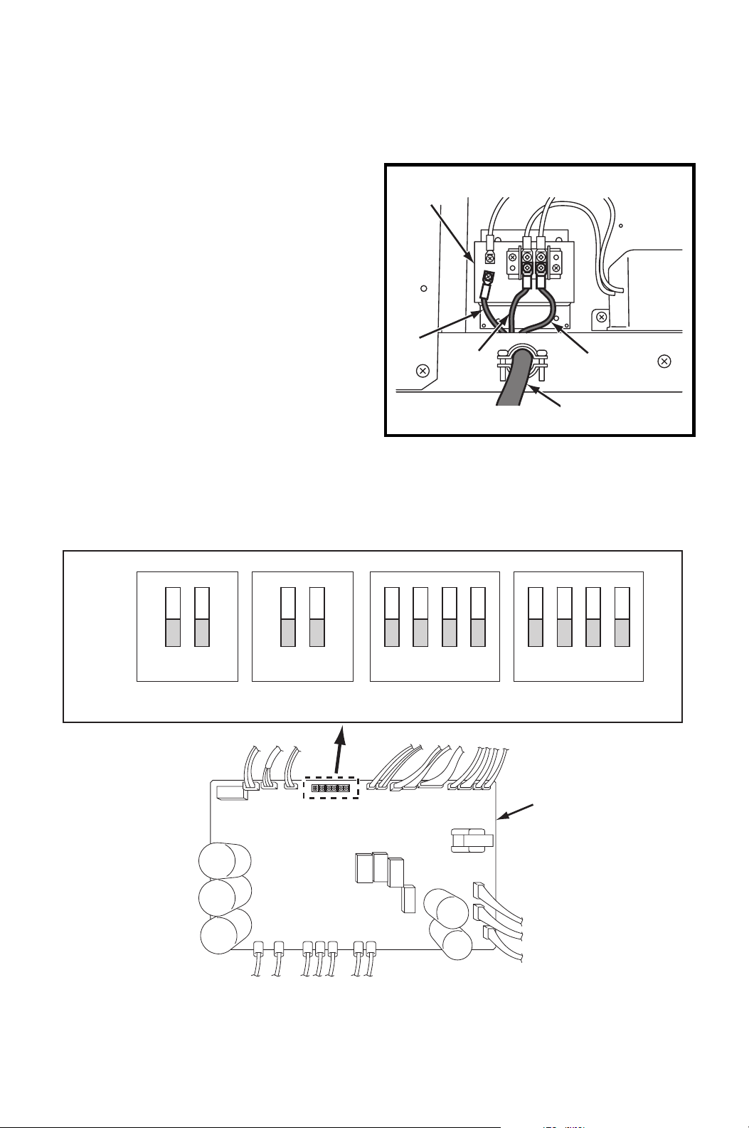
5. Connect the line wire (“R” and “T”) to
the terminal block. Tighten screw at
about 0.96 ft•lbf (1.3 N•m) torque.
6. Connect the ground wire (“G”) to the
terminal block. Tighten screw at
about 0.96 ft•lbf (1.3 N•m) torque.
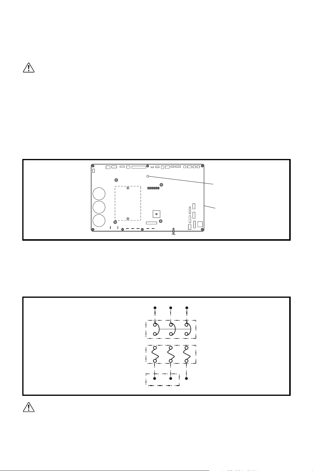
DIP Switch Configuration and Setting
The controller of the unit is equipped with DIP switches, which default in the OFF
position. The DIP switch can be set to configure the following functions.
RTG
POWER CORD
TR
G
TERMINAL
BLOCK
ILL00271-00
RELAY BOARD
ON
OFF
12
12 12341234
DSW1 DSW2 DSW3 DSW4
ILL00290-00
25
INSTALLATION (cont.)
DIP Switch Configuration and Setting (cont.)
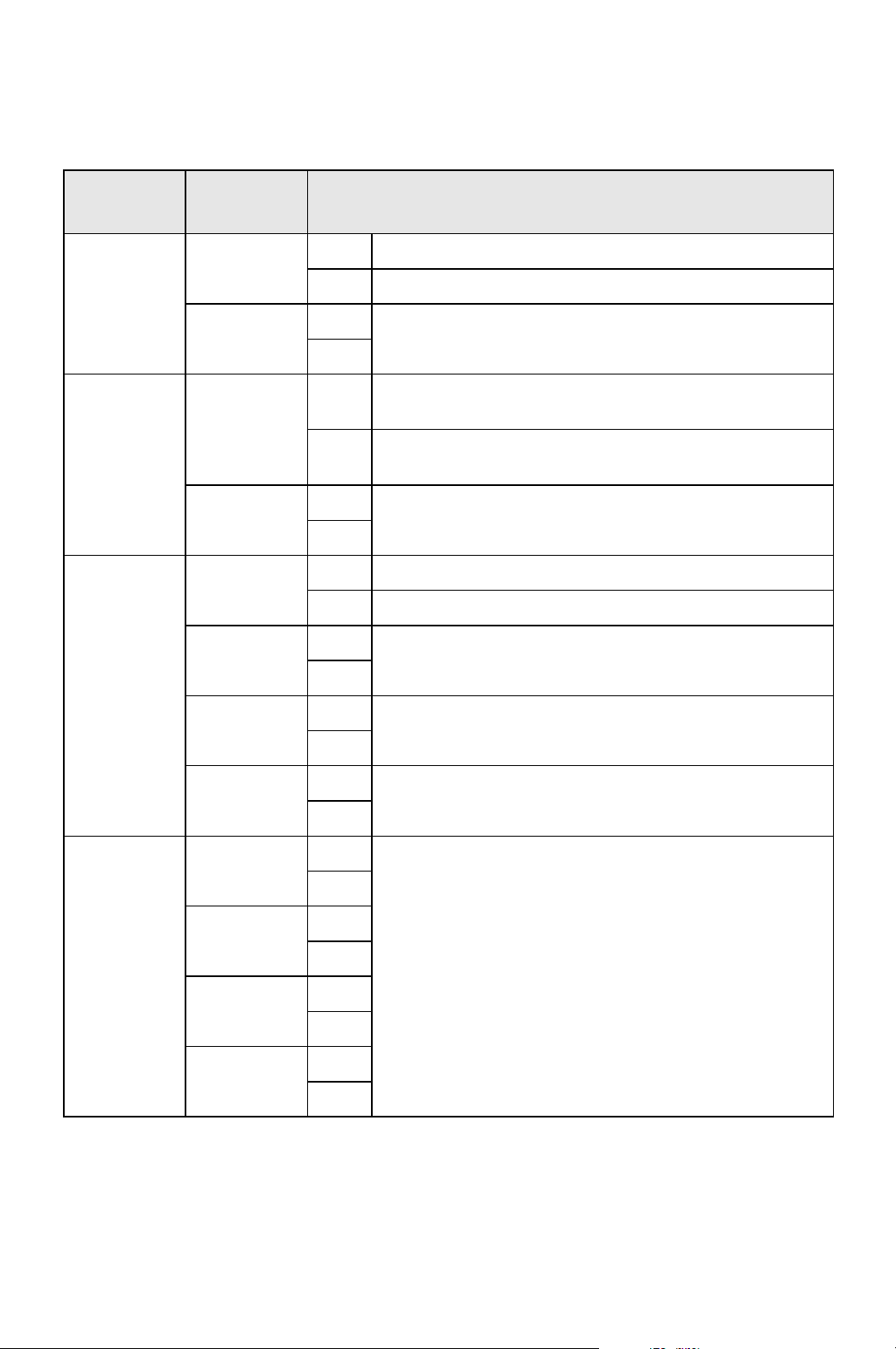
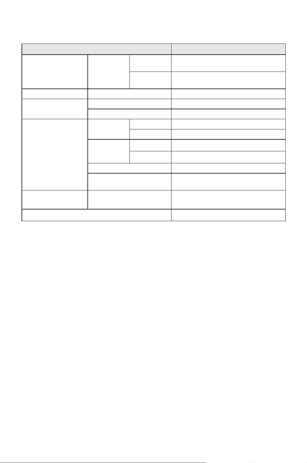
Switch
Name
Switch
Number
Function
DSW1
1
ON Enables the millivolt wall thermostat.
OFF Enables the wall mounted controller.
2
ON
No function.
OFF
DSW2
1
ON
Initializes setting of the evaporator fan motor after
replacing the fan motor.
OFF
Set to OFF when the motor replacement is
completed.
2
ON
No function.
OFF
DSW3
1
ON Enters the test mode.
OFF Exits the test mode.
2
ON
No function.
OFF
3
ON
No function.
OFF
4
ON
No function.
OFF
DSW4
1
ON
No function.
OFF
2
ON
OFF
3
ON
OFF
4
ON
OFF
26
INSTALLATION (cont.)
Supplied Wall Mounted Controller Connection
Set up the wall mounted controller without power connection on the unit.
Otherwise, the wall mounted controller set up will not be completed.
WARNING:
1. All electrical work should only be performed by qualified personnel.
Repair to electrical components by non-certified technicians may
result in personal injury and/or damage to the unit.
2. Disconnect power before any electrical installation. Beware that
some residual voltage may remain in the unit immediately after the
power is disconnected.
3. Do not touch the relay board of the unit until the green LED7 is
turned off. Failure to follow this warning may lead to electrical
shock.
Note: When the wall mounted controller of other model is connected, the lowest
set point temperature is 60 °F (16 °C). The model name label is attached on the
controller’s back cover.
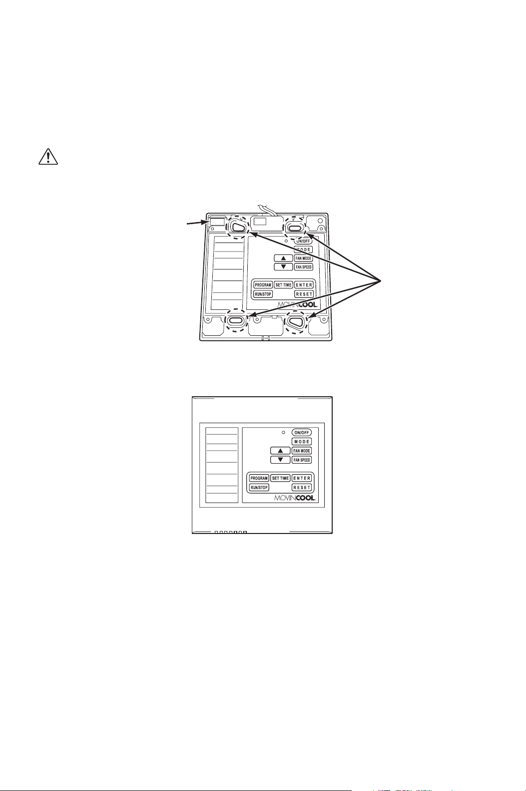
1. Push the stopper located at the bottom of the controller. Then remove the front
cover.
LED 7
ILL00697-00
16
Relay Board
FRONT COVER
STOPPER
ILL00292-00
27
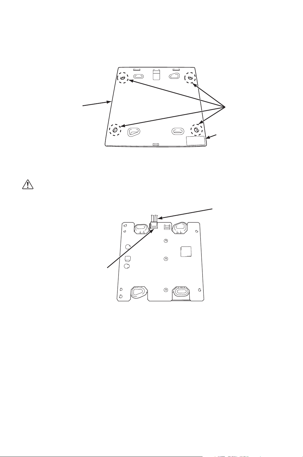
INSTALLATION (cont.)
Supplied Wall Mounted Controller Connection (cont.)
2. Remove four (4) screws from the back cover.
3. Connect the supplied shield wire (12 feet) to the 3-pin connector on the
controller board.
CAUTION: To avoid static electricity, do not touch the solder joints
or the none-insulated parts on the controller board.
SCREWS (4)
MODEL NAME
LABEL
BACK COVER
ILL00293-00
SHIELD WIRE
3-PIN CONNECTOR
ILL00294-00
28
INSTALLATION (cont.)
Supplied Wall Mounted Controller Connection (cont.)
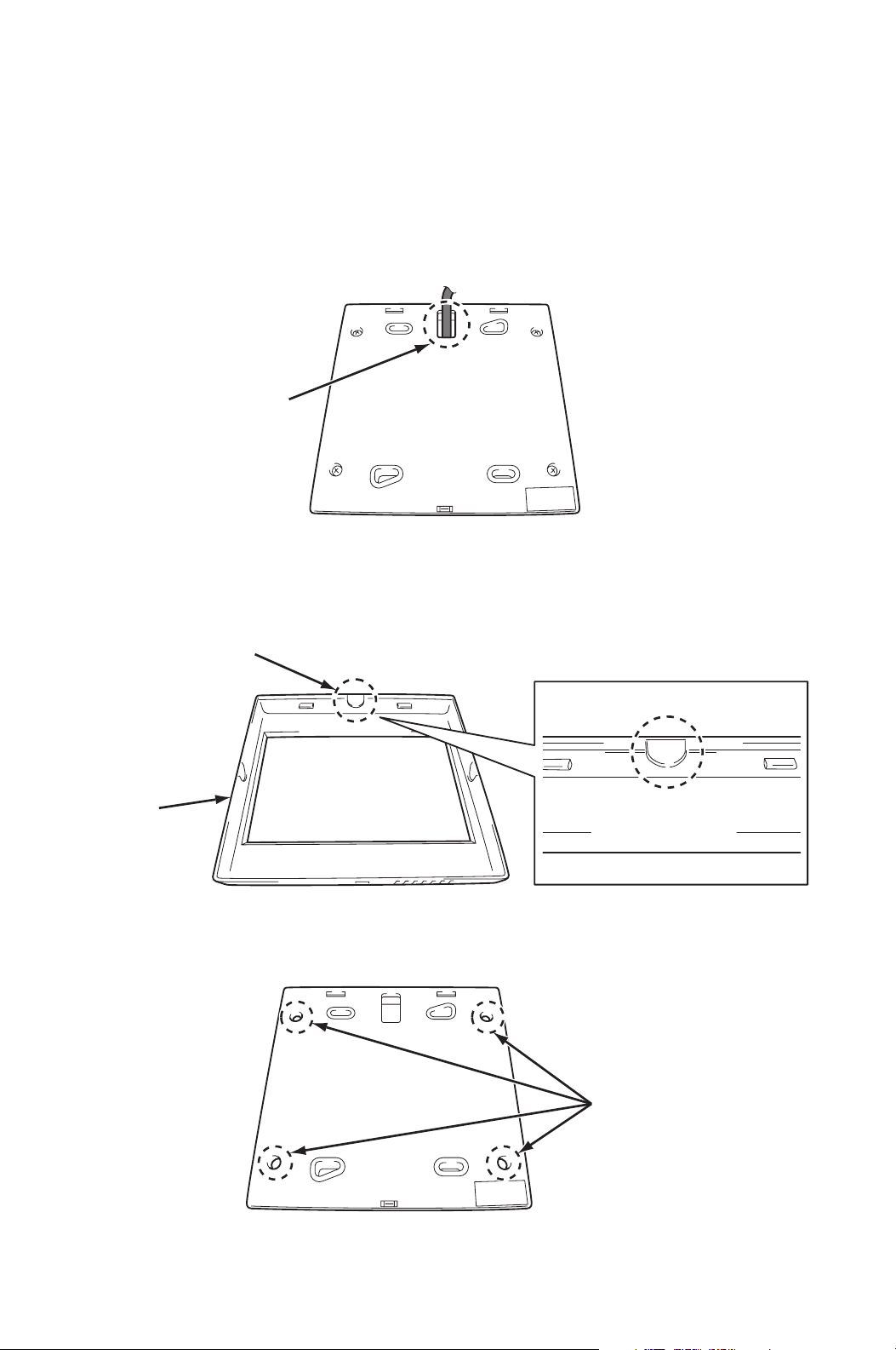
4. Depending on installation conditions, there are two methods to insert the
shield wire through the back cover of the controller.
Method A)
Insert the shield wire through the hole of the back cover.
Method B)
Break the dent portion of the front cover by tool (pliers, etc.). Remove the dent
portion and insert the shield wire through the hole.
5. Reassemble the controller board to the back cover with four (4) screws.
HOLE
ILL00295-00
FRONT
COVER
DENT PORTION
ILL00296-00
HOLES
ILL00297-00
29
INSTALLATION (cont.)
Supplied Wall Mounted Controller Connection (cont.)
6. Select the proper location where the controller can be conveniently accessed.
Install the controller assembled in step 5. to the wall with supplied four (4)
screws through the holes.
CAUTION: Do not install the controller where artificial heating
condition may occur (i.e.hot stove, hot pipe, fireplace or under
direct sunlight).
7. Reassemble the front cover.
8. Strip the end of the shield wire of the wall mounted controller.
HOLES
PART NUMBER
LABEL
ILL00298-00
ILL00299-00
30
INSTALLATION (cont.)
Supplied Wall Mounted Controller Connection (cont.)
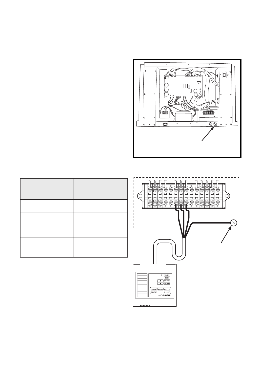
9. Disconnect power before connecting the wall mounted controller to the unit.
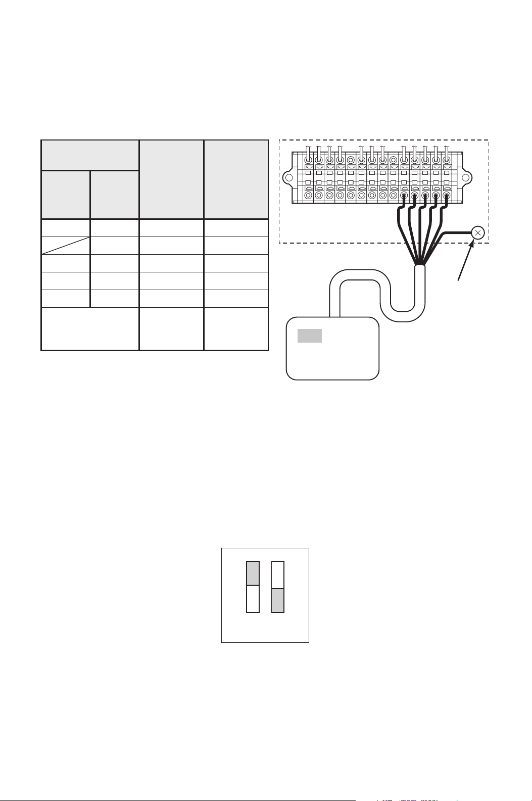
10. Insert the shield wire through the
wall mounted controller wire inlet.
Connect the shield wire to the
terminal block referring to the
connection table shown below.
Note: If wiring needs to be extended, a
maximum extension wire can be
extended up to 316 feet.
Shield wire 16-22 AWG is recommended
to use as an extension wire to reduce
noise interference.
Recommended extension wire: Shield
wire 16-22 AWG, Length 316 feet
maximum
Note: Do not connect the controller to AC or DC power source.
WALL MOUNTED
CONTROLLER WIRE INLET
ILL00300-00
L–
L+
E–
E+
G4
C4
P
RC
Y1
Y2
G
G1
G
UNIT TERMINAL
WALL MOUNTED
CONTROLLER
GROUND
SCREW
CONNECTION TABLE
P (Red)
C4 (White)
G4 (Black)
Shield Conductor
(Green)
P
Wall Mounted
Controller
Wire No. (Color)
Unit
Terminal No.
C4
G4
G
(Ground Screw)
ILL00301-00
31
INSTALLATION (cont.)
Supplied Wall Mounted Controller Connection (cont.)
11. DIP switch #1 of DSW1 on the relay board must be in the OFF position to use
the wall mounted controller.
Note:
1. Default position of all DIP switches are the OFF position.
2. If #1 switch of DSW1 is in the ON position, the millivolt wall thermostat is
enabled.
Field-Supplied Millivolt Wall Thermostat Connection
Set up the millivolt wall thermostat without power connection on the unit.
Otherwise, the wall thermostat set up will not be completed.
WARNING:
1. All electrical work should only be performed by qualified personnel.
Repair to electrical components by non-certified technicians may
result in personal injury and/or damage to the unit.
2. Disconnect power before any electrical installation. Beware that
some residual voltage may remain in the unit immediately after the
power is disconnected.
3. Do not touch the relay board of the unit until the green LED7 is
turned off. Failure to follow this warning may lead to electrical
shock.
ON
OFF
12
DSW1
ILL00302-00
LED 7
ILL00697-00
16
Relay Board
32
INSTALLATION (cont.)
Field-Supplied Millivolt Wall Thermostat Connection
(cont.)
1. Use with a single or multi stage system wall thermostat.
Thermostat type: Millivolt system
2. Set the wall thermostat to cooling system mode, since most wall thermostats
are designed for both heating and cooling.
3. Select the proper location where the wall thermostat can be conveniently
accessed. Install the wall thermostat to the wall at the selected location.
CAUTION: Do not install the wall thermostat where artificial heating
condition may occur (i.e.hot stove, hot pipe, and fireplace or under
direct sunlight).
Most thermostats provide these basic functions:
Fan Mode: On/Auto (Select the desired fan mode)
System: Cool/Heater (Select Cool only)
4. Disconnect power before connecting the wall thermostat to the unit.
5. Connect the wall thermostat to the
terminal block referring to the
connection table shown below.
Recommended extension wire:
Solid wire 16-26 AWG
MILLIVOLT WALL
THERMOSTAT WIRE INLET
ILL00303-00
33
INSTALLATION (cont.)
Field-Supplied Millivolt Wall Thermostat Connection
(cont.)
Note:
1. Terminal No. G1 is used only with the wall thermostat that has Fan Hi-Lo speed
control.
2. Use the wall thermostat that is compatible with the millivolt system.
Do not connect the wall thermostat to AC or DC power source.
6. DIP switch #1 of DSW1 on the relay board must be in the ON position to use
the millivolt wall thermostat.
Note:
1. Default position of all DIP switches are the OFF position.
2. If #1 switch of DSW1 is in the OFF position, the wall mounted controller is
enabled.
L–
L+
E–
E+
G4
C4
P
RC
Y1
Y2
G
G1
G
UNIT TERMINAL
GROUND
SCREW
WALL THERMOSTAT
(Example of the multi stage system)
CONNECTION TABLE
Wall Thermostat
Terminal No.
Unit
Terminal
No.
Function
Single-
Stage
System
RC
Y
G
(G1)
R
Y1
Y2
G
(G1)
Common
Cool MIN
Cool MAX
Fan Hi
(Fan Lo)
RC
Y1
Y2
G
(G1)
(Shield Wire) Ground
G
(Ground
Screw)
Multi-
Stage
System
ILL00304-00
ON
OFF
12
DSW1
ILL00305-00
34
INSTALLATION (cont.)
Warning Signal Connection (Output Signal)
The unit is equipped with a warning signal output relay type (Form-C, normal open
dry contact), which can be used to monitor the failure conditions.
Relay contactor is closed when any of the following conditions has occurred:
• Condensation overflows
• Temperature sensor fails
• Cooling function fails
The relay output contactor is rated 5 A at 30 VDC or 5 A at 250 VAC (resistive
load), and it is compatible with various warning devices such as alarm speakers,
light indicators, etc.
Connecting Warning Signal to CMW30
WARNING:
1. All electrical work should only be performed by qualified personnel.
Repair to electrical components by non-certified technicians may
result in personal injury and/or damage to the unit.
2. Disconnect power before any electrical installation. Beware that
some residual voltage may remain in the unit immediately after the
power is disconnected.
3. Do not touch the relay board of the unit until the green LED7 is
turned off. Failure to follow this warning may lead to electrical
shock.
1. Use recommended warning signal wire size from 16 AWG to 26 AWG for a
solid wire, or 16 AWG to 22 AWG for a stranded wire.
2. Disconnect power before connecting the warning signal wire to the unit.
3. Insert the warning signal wire through the
signal wire inlet.
LED 7
ILL00697-00
16
Relay Board
SIGNAL WIRE INLET
ILL00306-00
35
INSTALLATION (cont.)
Warning Signal Connection (Output Signal) (cont.)
Connecting Warning Signal to CMW30 (cont.)
4. Connect the warning signal wires to terminal L+ and L- in the unit control box
according to the labels shown below.
Fire Alarm Connection (Input Signal)
The unit is equipped with a normal open input signal connection, which can be
connected directly from the fire alarm control panel. When receiving the signal
from the fire alarm control panel, the unit turns off and does not turn back on until
power source is reset or turns the wall mounted controller or wall thermostat off
and on.
Connecting Fire Alarm Signal to CMW30
WARNING:
1. All electrical work should only be performed by qualified personnel.
Repair to electrical components by non-certified technicians may
result in personal injury and/or damage to the unit.
2. Disconnect power before any electrical installation. Beware that
some residual voltage may remain in the unit immediately after the
power is disconnected.
L–
L+
E–
E+
G4
C4
P
RC
Y1
Y2
G
G1
UNIT TERMINAL
WARNING DEVICE
INPUT SIGNAL
RELAY OUTPUT CONTACTOR
ILL00307-00
36
INSTALLATION (cont.)
Fire Alarm Connection (Input Signal) (cont.)
Connecting Fire Alarm Signal to CMW30 (cont.)
3. Do not touch the relay board of the unit until the green LED7 is
turned off. Failure to follow this warning may lead to electrical
shock.
1. Use recommended fire alarm signal wire size from 16 AWG to 26 AWG for a
solid wire, or 16 AWG to 22 AWG for a stranded wire.
2. Disconnect power before connecting the fire alarm signal wire to the unit.
3. Insert the fire alarm signal wire through the
signal wire inlet.
4. Connect the fire alarm signal wires to terminal E+ and E- in the unit control box
according to labels shown below.
LED 7
ILL00697-00
16
Relay Board
SIGNAL WIRE INLET
ILL00306-00
L–
L+
E–
E+
G4
C4
P
RC
Y1
Y2
G
G1
UNIT TERMINAL
FIRE ALARM DEVICE
OUTPUT SIGNAL
OPEN DRY CONTACT
ILL00308-00

37
FEATURES OF CMW30
1. This unit is equipped with a variable speed compressor, which is driven by
state of the art inverter technology. A variable speed compressor automatically
adjusts its speed as the heat load in the room changes. With its soft start up,
a variable speed compressor reduces start up wear on the compressor and
eliminates in-rush current resulting in no dip in the power supply.
2. Fire alarm control panel connection with automatic shut off.
3. Automatic shut off by warning signal output and alarm for temperature sensor
failure, and conditions of self-diagnostic codes.
4. Automatic restart feature when the power is lost and regained.
The unit returns to the operating mode it was in prior to the loss of power.
Any preset program is retained in the memory in the event power loss occurs.
FEATURES OF WALL MOUNTED
CONTROLLER
1. Supplied wall mounted controller allows the user to easily control the unit’s
operation.
2. LCD display that indicates:
a. Clock with day and time
b. Room temperature and set point temperature (either Fahrenheit or Celsius)
c. Operation mode status
d. Fan mode status
e. Fan speed status
f. Set program status
g. Program run and stop
h. Self-diagnostic codes
i. Keypad lock
3. Programmable operation control. This function allows the user to program
automatic operation which includes time and day of unit start and/or stop, fan
mode, fan speed, and set temperature.
38
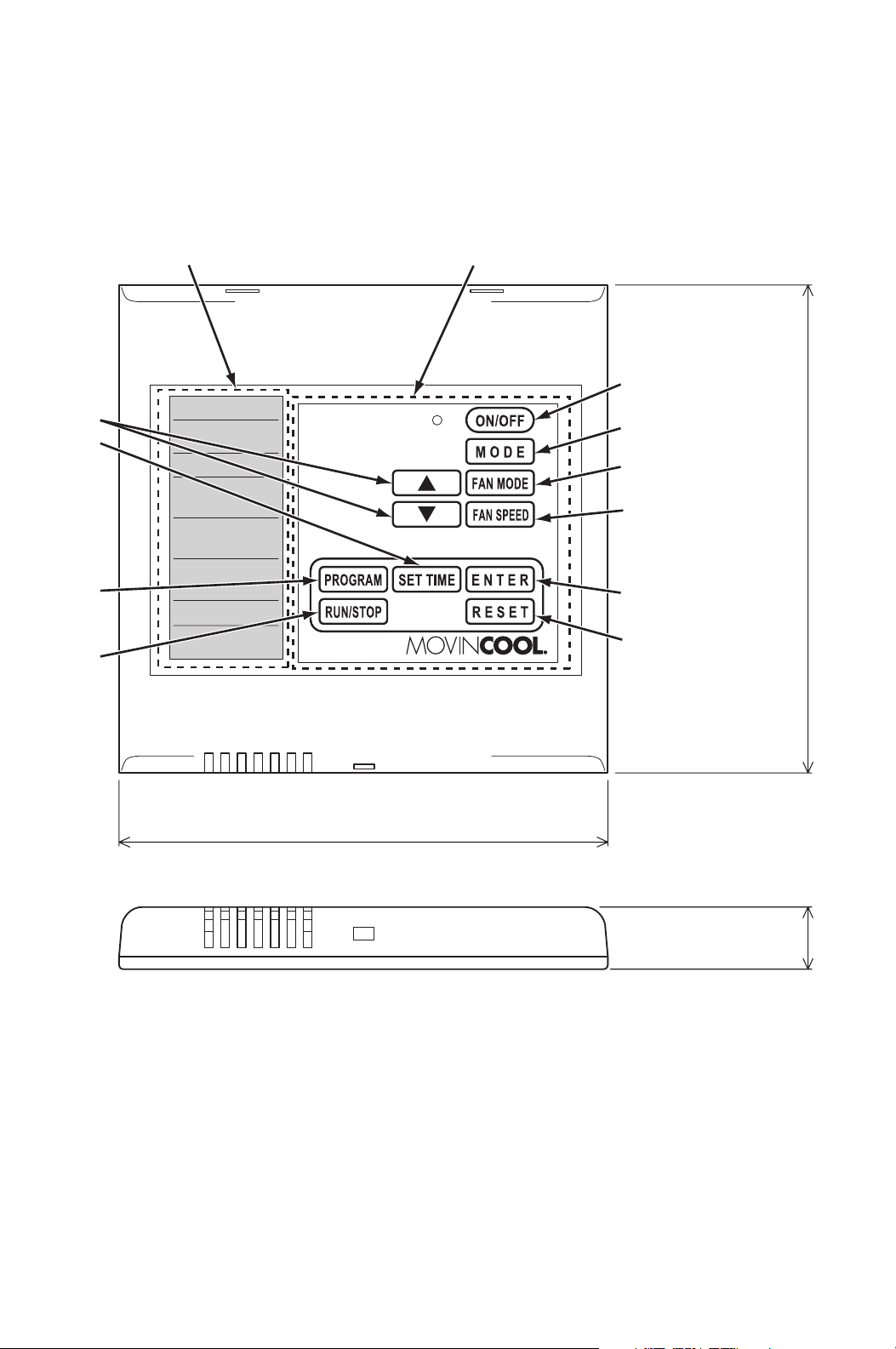
OPERATION (Wall Mounted Controller ONLY)
Control Panel
Before operating the unit, it is important to familiarize yourself with the basic
controls located on the control panel.
4.8 in (120 mm)
4.8 in (120 mm)
0.6 in (15 mm)
LCD DISPLAY OPERATION PANEL
8
10
4
3
2
1
5
7
6
9
ILL00309-00

39
OPERATION
(Wall Mounted Controller ONLY) (cont.)
Control Panel (cont.)
1. ON/OFF Button Activates (LED illuminates green) or deactivates
unit operation.
2. MODE Button Activates COOL or FAN ONLY operation.
3. FAN MODE Button Activates fan mode RUN or AUTO.
RUN: Fan operates continuously during COOL
mode even after the room temperature
reaches the set point temperature.
RUN mode is automatically selected when
FAN ONLY mode is selected.
AUTO: Fan automatically stops during COOL
mode after the room temperature reaches
the set point temperature. Fan
automatically operates when the room
temperature is above the set point
temperature.
4. FAN SPEED Button Activates fan speed High or Low.
5. UP ( ) & DOWN ( )
Buttons
Increases or decreases the temperature set point
during COOL mode.
Selects each item when setting clock or program.
6. PROGRAM Button Sets or displays program.
7. SET TIME Button Sets clock (day and time).
8. ENTER Button Accepts selection and goes to the next step.
9. RUN/STOP Button Activates or deactivates program(s).
10. RESET Button • Clears self-diagnostic codes.
• Returns to “Day of the week” for “ON” (start)
program setting during program editing mode.
• Clears all program memory during program
editing mode by pressing and holding the RESET
button for 3 seconds.
40
OPERATION
(Wall Mounted Controller ONLY) (cont.)
Control Panel (cont.)
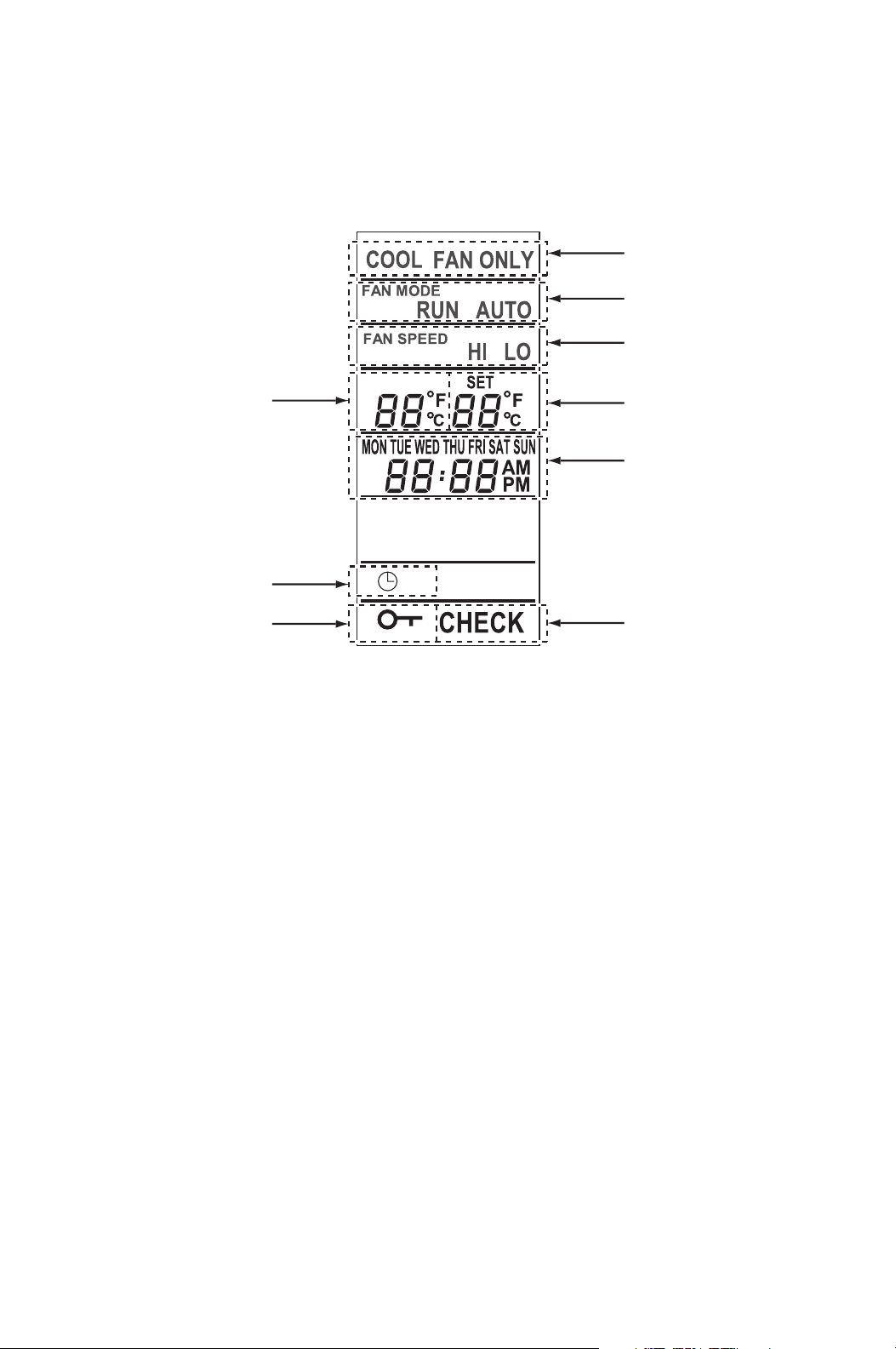
Note:
1. The room temperature display range is from 16 °F (-9 °C) to 140 °F (60 °C).
When the display value is greater than 99 °F, it displays values of 00F (for 100
°F), 01F (for 101 °F) and 09F (for 109 °F).
2. When the wall mounted controller of other model is connected, the lowest set
point temperature is 60 °F (16 °C). The model name label is attached on the
wall mounted controller’s back cover.
11. COOL or FAN ONLY Illuminates to indicate COOL on or FAN ONLY on.
12. RUN or AUTO Illuminates to indicate fan mode set to RUN or
AUTO.
13. HI or LO Illuminates to indicate fan speed set to High or
Low.
14. Room temperature Illuminates temperature in either Fahrenheit (°F) or
Celsius (°C) (see Note).
15. Set temperature Illuminates temperature in either Fahrenheit (°F) or
Celsius (°C) in COOL mode. The temperature
range is from 55 °F (13 °C) to 95 °F (35 °C).
16. Day of the week and
time
Illuminates to indicate day of the week and time.
17. Clock symbol Illuminates to indicate program is running.
18. Key symbol Illuminates to indicate keypad locked.
19. CHECK Illuminates with self-diagnostic codes.
11
14
17
18
12
13
15
16
19
LCD DISPLAY
ILL00310-00
41
OPERATION
(Wall Mounted Controller ONLY) (cont.)
Standby Mode
When power source is supplied to the unit, the wall mounted controller is in
standby mode.
During standby mode, the control panel displays time.
Set Clock
Prior to operating the unit, set the clock of the controller to the correct time as
shown in the steps below.
1. Press and hold the SET TIME button for 3 seconds. “Day of the week” blinks.
2. Press UP ( ) or DOWN ( ) button to select “Day of the week”.
3. Press ENTER button. “Hour” blinks.
4. Press UP ( ) or DOWN ( ) button to select correct hour.
Note: AM or PM changes with hour automatically.
5. Press ENTER button. “Minutes” blinks.
6. Press UP ( ) or DOWN ( ) button to select correct minute.
7. Press ENTER button to complete clock setting.
Note:
1. Check clock periodically to confirm clock accuracy.
2. The clock defaults after 20 days from the point of shutting power supply. In this
case, set the clock again.

42
OPERATION
(Wall Mounted Controller ONLY) (cont.)
Operate in COOL Mode
When in COOL mode, the compressor is operated and cool air is circulated.
1. Press ON/OFF button. LED (green) illuminates.
2. Press MODE button and select “COOL”.
3. Press FAN MODE button to select “RUN” or “AUTO”.
RUN: Fan operates continuously during COOL mode even after the room
temperature reaches the set point temperature.
RUN mode is automatically selected when FAN ONLY mode is
selected.
AUTO: Fan automatically stops during COOL mode after the room
temperature reaches the set point temperature. Fan automatically
operates when the room temperature is above the set point
temperature.
4. Press FAN SPEED button to select the fan speed “HI” or “LO”.
5. Press UP ( ) or DOWN ( ) button to select the temperature set point.
6. To stop COOL operation, press ON/OFF button.
Note: Compressor continuously operates for minimum 2 minutes to protect the
refrigerant system once started. During this condition, “COOL” blinks.

43
OPERATION
(Wall Mounted Controller ONLY) (cont.)
Operate in FAN ONLY Mode
When in FAN ONLY mode, the unit circulates the surrounding air.
1. Press ON/OFF button. LED (green) illuminates.
2. Press MODE button and select “FAN ONLY”.
Note: Fan mode “RUN” is automatically set (no selection of “AUTO”) when
FAN ONLY is selected.
3. Press FAN SPEED button to select the fan speed “HI” or “LO”.
Change Mode
While in COOL mode, press MODE button to select FAN ONLY mode.
When in FAN ONLY mode, press MODE button to select COOL mode.
Change Temperature Scale
The temperature scale can be changed.
Press and hold UP ( ) and DOWN ( ) buttons simultaneously for 3 seconds to
change “°C” (Celsius) or “°F” (Fahrenheit).
Keypad Lock
Keypad lock disables all buttons on the control panel except keypad lock and
unlock operations.
1. To lock, press and hold ENTER and RESET buttons simultaneously for 3
seconds.
2. To unlock, press and hold ENTER and RESET buttons simultaneously for 3
seconds again.
Note: When the unit detects operation failure, keypad is unlocked automatically
and self-diagnostic code illuminates.
Program Feature
• Ten program sequences are available (“Pr 01” to “Pr 10”).
• Each program sequence contains set “ON” (start) time, operation mode,
and “OFF” (stop) time.
• Each program is confirmed when “ON” (start) time and “OFF” (stop) time
are set.
• Exits program mode if any button is not pressed for 1 minute while
programming.
• Program runs sequentially from “Pr 01” to “Pr 10” sequence.
• The preceding program is copied to the next program automatically.
• During program RUN mode, all keypad is locked except RUN/STOP button.
To exit program RUN mode, press and hold RUN/STOP button for 3 seconds.
44
OPERATION
(Wall Mounted Controller ONLY) (cont.)
Program Setting
To program the controller, read the instructions on page 45 to 47 and follow the
flow chart shown below.
Press and hold
for 3 seconds.
Select program No.
(Pr 01 to Pr 10)
Blinking.
orPress
ON (start)
Program
Setting
OFF (stop)
Program
Setting
or
Press
Select
each Item.
Selecting
item blinks.
OFF (stop)
Program
Display
(default)
Program
sequence
No. Display
Press and hold for 3 seconds.
Defaults all programs.
ON (start)
Program
Display
(default)
Selecting
item blinks.
Select
Press
Press
Press
Press
Press
Press
Press
Press
Press
Press
Press
Day of the week
Hour
Minutes
Operation
mode
Fan mode
Fan speed
Set temp.
Day of the
week
Hour
Minutes
Enter programExit program
Press
Edits previous
settings.
ILL00311-00
45
OPERATION
(Wall Mounted Controller ONLY) (cont.)
Select Program Sequence Number
1. Press and hold PROGRAM button for 3 seconds. “Pr
01” blinks.
Note: If any button is not pressed for 3 seconds,
program moves to the next step (selecting “Day of
the week”) automatically.
2. Press UP ( ) or DOWN ( ) button to scroll
program sequences.
3. Press ENTER button to select the program
sequence number.
Set Start Time and Operation Mode
4. “On” (program setting for unit ON) illuminates and
“Day of the week” blinks.
Press UP ( ) or DOWN ( ) button to select “Day
of the week”.
Press ENTER button. “Hour” blinks.
5. Press UP ( ) or DOWN ( ) button to select “hour”.
Press ENTER button. “Minutes” blinks.
Note: AM or PM changes with hour automatically.
6. Press UP ( ) or DOWN ( ) button to select
“minutes”.
Press ENTER button. “COOL” blinks.
7. Press UP ( ) or DOWN ( ) button to select mode “COOL” or “FAN ONLY”.
Press ENTER button. “RUN” blinks.
Note: Fan mode “RUN” is automatically set (no selection of “AUTO”) when
FAN ONLY is selected.
8. Press UP ( ) or DOWN ( ) button to select fan mode “RUN” or “AUTO”.
Press ENTER button. “HI” blinks.
9. Press UP ( ) or DOWN ( ) button to select fan speed “HI” or “LO”.
Press ENTER button. “Set temperature” blinks.
10. Press UP ( ) or DOWN ( ) button to select “Set temperature”.
Press ENTER button. “OF” (program setting for unit OFF) illuminates and
“Day of the week” blinks.
Note: To change the previous settings, press RESET button and start again
from “Day of the week” setting.
ILL00312-00
ILL00313-00
46
OPERATION
(Wall Mounted Controller ONLY) (cont.)
Set Stop Time
11. Press UP ( ) or DOWN ( ) button to select “Day
of the week”.
Press ENTER button. “Hour” blinks.
12. Press UP ( ) or DOWN ( ) button to select “hour”.
Press ENTER button. “Minutes” blinks.
Note: AM or PM changes with hour automatically.
13. Press UP ( ) or DOWN ( ) button to select
“minutes”. Press ENTER button. “Pr 02” illuminates.
Note: To change the previous settings, press
RESET button and start again from “Day of the
week” setting.
Repeat step 1. to 13. to set up program sequences from “Pr 02” to “Pr 10”.
Note: Program counts period from the start time and day of “Pr 01” to the stop time
and day of the last program. Program period can not be overlapped. Overlapped
time period input can not be accepted by the controller.
Exit Program Mode
14. Press PROGRAM button for 3 seconds to exit program mode.
View Program
1. Press PROGRAM button.
2. Press UP ( ) or DOWN ( ) button to select the desired program sequence.
3. Press ENTER button. Detail of “ON” program (start time and operation mode
setting) is displayed.
4. Press ENTER button. Detail of “OFF” program (stop time) is displayed.
5. Press ENTER button. Returns to the select program view.
6. Press PROGRAM button to exit.
ILL00314-00

47
OPERATION
(Wall Mounted Controller ONLY) (cont.)
Edit Program
1. Press and hold PROGRAM button for 3 seconds. “Pr 01” blinks.
2. Press UP ( ) or DOWN ( ) button to select program sequence (“Pr 01” to
“Pr 10”).
Press ENTER button.
3. Press UP ( ) or DOWN ( ) button to select the item to be edited.
Press ENTER button.
4. Press and hold PROGRAM button for 3 seconds to exit.
Delete Program
To clear all programs (“Pr 01” to “Pr 10”), press and hold RESET button for 3
seconds during program editing mode.
Note: All program are set to default (see page 44 for the default program displays).
Run and Stop Program
1. Press and hold RUN/STOP button for 3 seconds to activate preset program
(clock symbol is displayed).
Program runs from “Pr 01” to “Pr 10”.
2. Press and hold RUN/STOP button for 3 seconds to stop program.
Note:
1. Confirm your program before running the program.
2. During program RUN, the keypad is locked except RUN/STOP button. To
unlock, press “RUN/STOP” button.
3. When the unit detects operation failure, program “RUN” is automatically
cancelled and displays self-diagnostic code.
4. Program runs sequentially from “Pr 01” to “Pr 10” sequence.
5. Programming must be done sequentially.
48
OPERATION
(Wall Mounted Controller ONLY) (cont.)
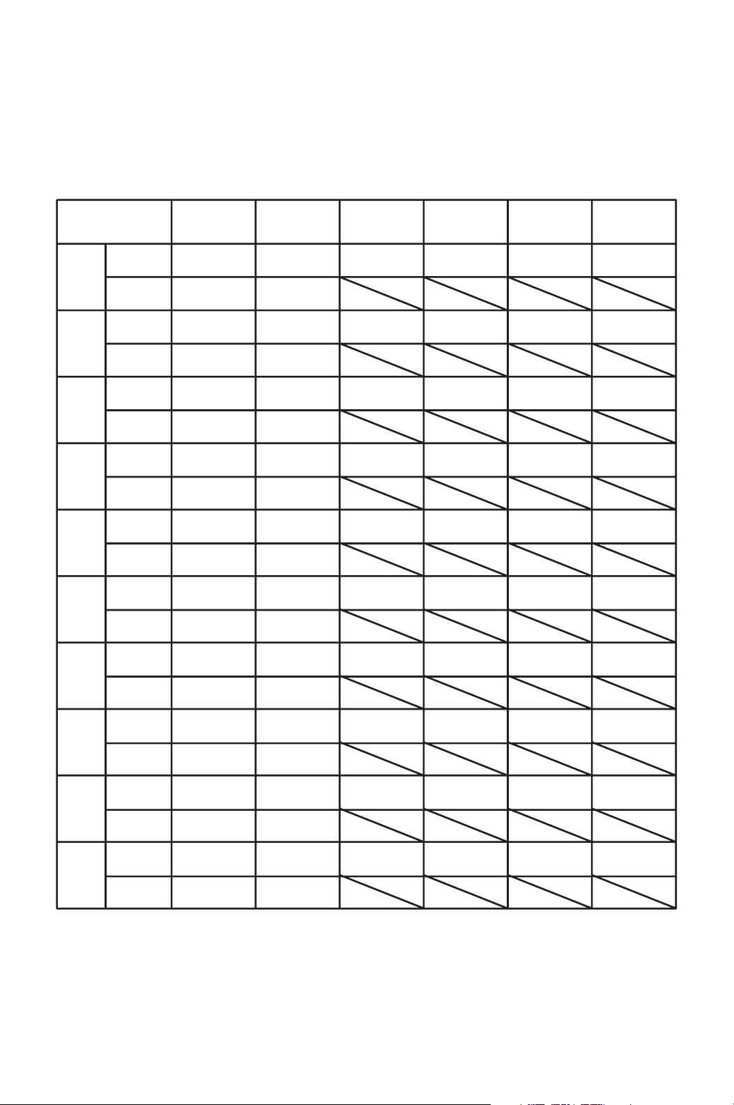
Program Plan Sheet
START
Pr 01
STOP
START
Pr 02
STOP
START
Pr 03
STOP
START
Pr 04
STOP
START
Pr 05
STOP
START
Pr 06
STOP
START
Pr 07
STOP
START
Pr 08
STOP
START
Pr 09
STOP
START
Pr 10
STOP
Day of the
week
Time Mode Fan mode Fan speed Set Temp.
Program Plan
49
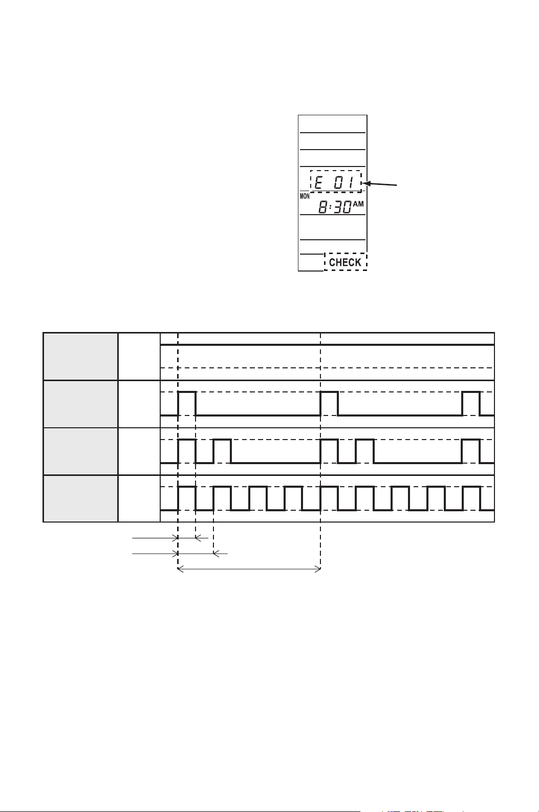
SELF-DIAGNOSTIC CODES & BUZZER
PATTERN
Self-Diagnostic Codes
Self-diagnostic codes are displayed with
“CHECK” on LCD panel of the supplied
wall mounted controller under the following
conditions.
Note: When using the field supplied wall
thermostats, the self-diagnostic codes are
not displayed. Check buzzer pattern to
distinguish each code. For remedy, see
“Troubleshooting” from page 53 to 59.
Buzzer Pattern
Self-Diagnostic
code
ILL00316-00
ILL00318-00
0.5 sec
1 sec
4 sec
Pattern 1
Pattern 2
Pattern 3
Pattern 4
ON
OFF
ON
OFF
ON
OFF
ON
OFF
50
SELF-DIAGNOSTIC CODES & BUZZER
PATTERN (cont.)
Table of Self-Diagnostic Codes
Self-Diagnostic
codes
(Wall mounted
controller only)
Buzzer
Pattern
Condition Remedy
AL 1 Fire alarm is activated.
See
“Troubleshooting”
from page 53 to
59.
PU
3
Overflow protection is activated
(internal pump).
E07
Overflow protection is activated
(optional pump).
HP 4 High pressure protection is activated.
E01
2
Sensor fail
(RTS1: Wall mounted controller room
thermistor)
E02
Sensor fail
(RTS2: Evaporator air inlet thermistor)
E03
Sensor fail
(EWTS: Entering water thermistor)
E04
Sensor fail
(CTS1: Condenser thermistor)
E05
Sensor fail
(CTS2: Evaporator pipe inlet
thermistor)
E06
Sensor fail
(CTS3: Evaporator pipe outlet
thermistor)
E08
4
Wall thermostat communication error
E09
Evaporator fan motor over current
protection is activated.
OL
Compressor overload protection is
activated.
E11 Relay board communication error
E12 Compressor error
E13 Relay board error
E23
Evaporator fan motor over rotation
protection is activated.

51
INSPECTION & MAINTENANCE
Cleaning Air Filters
The air filter on the evaporator return grill should be checked weekly for dust
buildup.
Clean or replace air filter on a weekly basis. If the unit is used in a dusty
environment, more frequent cleaning may be required.
A dirty air filter can reduce the air output, resulting in a decrease in cooling
capacity.
Ground Fault Breaker Testing
The ground fault breaker should be tested at least once a month.
Inspection of Water Lines and Connections
The water lines, water condenser coil, and water connections should be inspected
periodically for leakage and/or condensation buildup.
52
TROUBLESHOOTING
Check the following conditions before calling your MovinCool reseller or a qualified
technician.
If conditions persist after the above remedies have been performed, turn off the
unit, disconnect the power, and contact your MovinCool reseller or a qualified
technician.
Condition Check Area Possible Cause Remedy
Unit
operates.
Insufficient
air volume
Filter Air filter is clogged. Clean or replace air filter.
Duct Leak or clog on the
duct connection
Repair duct connection.
Using longer duct
length or smaller
duct diameter than
recommended.
Change the duct to
proper size.
Fan Fan is locked. Remove any foreign
object causing fan lock.
Unit
does not
operate.
LCD
display
turns off.
1. Voltage Power failure Repair power supply.
Turn the circuit breaker
on.
2. Ground fault
breaker trip
Ground fault or
defective ground
fault.
Repair ground fault
section.
Reset or repair breaker.
3. Fuse Fuse is blown. Replace fuse on the
relay board.
4. Wall mounted
controller/
millivolt wall
thermostat
Incorrect connection Connect the wires
correctly. (See “Supplied
Wall Mounted Controller
Connection” on page 26
to 31 or “Field-Supplied
Millivolt Wall Thermostat
Connection” on page 31
to 33.)
DIP switch setting is
incorrect.
Correct DIP switch
setting. (See “DIP Switch
Configuration and
Setting” on page 24.)
5. Stop switch Stop switch is in the
STOP position.
Turn the stop switch to
the OPERATE position.
53
TROUBLESHOOTING (cont.)
If conditions persist after the above remedies have been performed, turn off the
unit, disconnect the power, and contact your MovinCool reseller or a qualified
technician.
Condition
Self-
Diagnostic
Codes
(Wall
mounted
controller)
Buzzer
Pattern
Possible Cause Remedy
Unit
does
not
operate.
LCD
displays
self-
diagnostic
codes.
AL 1 Signal is input to
the fire alarm
connection.
Connect the fire
alarm signal wires
correctly.
(See “Fire Alarm
Connection (Input
Signal) on page 35”.)
Press RESET
button, then press
ON/OFF button.
PU 3 Drain hose clogged
(for internal drain
pump).
Remove any
blockages or
excessive kinks
preventing water
flow.
Press RESET
button, then press
ON/OFF button.
Drain hose trap
position is too high
to pump up
condensation water
(for internal drain
pump).
Improve hose
installation.
(See “Drain Hose
Connection” on
page 18 to 19.)
Press RESET
button, then press
ON/OFF button.
Internal drain pump
is not working.
Connect the internal
drain pump
connector securely.
Press RESET
button, then press
ON/OFF button.
If the internal drain
pump still does not
work, replace it.
54
TROUBLESHOOTING (cont.)
If conditions persist after the above remedies have been performed, turn off the
unit, disconnect the power, and contact your MovinCool reseller or a qualified
technician.
Condition
Self-
Diagnostic
Codes
(Wall
mounted
controller)
Buzzer
Pattern
Possible Cause Remedy
Unit
does
not
operate.
LCD
displays
self-
diagnostic
codes.
E07 3 Drain hose is
clogged (for
optional drain
pump).
Remove any
blockages or
excessive kinks
preventing air flow.
Press RESET
button, then press
ON/OFF button.
Drain hose trap
position is too high
to pump up
condensation water
(for optional drain
pump).
Improve hose
installation.
(Refer to the
installation manual of
the optional drain
pump.)
Press RESET
button, then press
ON/OFF button.
Optional drain
pump is not
working.
Connect the drain
pump connector
securely.
Press RESET
button, then press
ON/OFF button.
If the optional drain
pump still does not
work, replace it.
55
TROUBLESHOOTING (cont.)
If conditions persist after the above remedies have been performed, turn off the
unit, disconnect the power, and contact your MovinCool reseller or a qualified
technician.
Condition
Self-
Diagnostic
Codes
(Wall
mounted
controller)
Buzzer
Pattern
Possible Cause Remedy
Unit
does
not
operate.
LCD
displays
self-
diagnostic
codes.
HP 4 Operating outside
of the operating
temperature range
Check
environmental
condition.
Do not operate the
unit outside the
operating condition
range. (See
“Technical
Specifications” on
page 61.)
Press RESET
button, then press
ON/OFF button.
Insufficient water
flow
Connect water inlet
and outlet of the unit
and water source
correctly.
Press RESET
button, then press
ON/OFF button.
Check water line,
and make sure there
is enough water flow.
(See “Technical
Specifications” on
page 61.)
Press RESET
button, then press
ON/OFF button.
Clean water system
to remove
accumulated
sediment. Contact a
qualified technician
for details.
Press RESET
button, then press
ON/OFF button.
56
TROUBLESHOOTING (cont.)
If conditions persist after the above remedies have been performed, turn off the
unit, disconnect the power, and contact your MovinCool reseller or a qualified
technician.
Condition
Self-
Diagnostic
Codes
(Wall
mounted
controller)
Buzzer
Pattern
Possible Cause Remedy
Unit
does
not
operate.
LCD
displays
self-
diagnostic
codes.
E01 Defective RTS1
thermistor
(short or open)
Replace the wall
mounted controller.
Press RESET
button, then press
ON/OFF button.
E02 2 Loose RTS2
thermistor
connection
Connect the
connector securely.
Press RESET
button, then press
ON/OFF button.
Defective RTS2
thermistor
(short or open)
Replace RTS2
thermistor.
Press RESET
button, then press
ON/OFF button.
E03 2 Loose EWTS
thermistor
connection
Connect the
connector securely.
Press RESET
button, then press
ON/OFF button.
Defective EWTS
thermistor
(short or open)
Replace EWTS
thermistor.
Press RESET
button, then press
ON/OFF button.
E04 2 Loose CTS1
thermistor
connection
Connect the
connector securely.
Press RESET
button, then press
ON/OFF button.
Defective CTS1
thermistor
(short or open)
Replace CTS1
thermistor.
Press RESET
button, then press
ON/OFF button.
57
TROUBLESHOOTING (cont.)
If conditions persist after the above remedies have been performed, turn off the
unit, disconnect the power, and contact your MovinCool reseller or a qualified
technician.
Condition
Self-
Diagnostic
Codes
(Wall
mounted
controller)
Buzzer
Pattern
Possible Cause Remedy
Unit
does
not
operate.
LCD
displays
self-
diagnostic
codes.
E05 2 Loose CTS2
thermistor
connection
Connect the
connector securely.
Press RESET
button, then press
ON/OFF button.
Defective CTS2
thermistor
(short or open)
Replace CTS2
thermistor.
Press RESET
button, then press
ON/OFF button.
E06 2 Loose CTS3
thermistor
connection
Connect the
connector securely.
Press RESET
button, then press
ON/OFF button.
Defective CTS3
thermistor
(short or open)
Replace CTS3
thermistor.
Press RESET
button, then press
ON/OFF button.
E08 Wall mounted
controller lost
communication
with the unit for
more than 10
seconds.
Check for connection
or interference.
Press RESET
button, then press
ON/OFF button.
E09 4 Evaporator fan
motor is locked.
Remove any foreign
object causing fan
lock.
Press RESET
button, then press
ON/OFF button.
58
TROUBLESHOOTING (cont.)
If conditions persist after the above remedies have been performed, turn off the
unit, disconnect the power, and contact your MovinCool reseller or a qualified
technician.
Condition
Self-
Diagnostic
Codes
(Wall
mounted
controller)
Buzzer
Pattern
Possible Cause Remedy
Unit
does
not
operate.
LCD
displays
self-
diagnostic
codes.
OL 4 Compressor
overload protection
is activated by
refrigerant leakage.
Repair the leaking
section and recharge
the correct amount of
refrigerant. Contact
your MovinCool
reseller or a qualified
technician.
Press RESET
button, then press
ON/OFF button.
E11 4 Relay board
communication
error occurs for 40
seconds.
Check all the wire
connections on the
relay board. Contact
your MovinCool
reseller or a qualified
technician.
Press RESET
button, then press
ON/OFF button.
59
TROUBLESHOOTING (cont.)
If conditions persist after the above remedies have been performed, turn off the
unit, disconnect the power, and contact your MovinCool reseller or a qualified
technician.
Condition
Self-
Diagnostic
Codes
(Wall
mounted
controller)
Buzzer
Pattern
Possible Cause Remedy
Unit
does
not
operate.
LCD
displays
self-
diagnostic
codes.
E12 4 Compressor error
due to the following
conditions:
1. Unit is operating
outside the
operating condition
range.
2. Electromagnetic
noise interference
3. Compressor
locked up
Press RESET button
on the controller, and
turn off the circuit
breaker, then turn on
the circuit breaker.
Press ON/OFF
button on the
controller.
E13 4 Relay board error
due to the following
conditions:
1. Electromagnetic
noise interference
2. Electrostatic
discharge and
interruption
E23 4 Evaporator fan
motor over rotation
Check ducting of
intake and exhaust
air, and remove any
foreign object
preventing the air
flow.
Press RESET
button, then press
ON/OFF button.
60
TECHNICAL SPECIFICATIONS
Item Specifications
Electronic Features Control Wall Mounted Controller (Included)
Set Point
Temperature
Range
Max. 95 °F (35 °C)
Min. 55 °F (13 °C)
Electrical
Characteristics
Voltage Requirement Single-Phase, 208/230 V, 60 Hz
Operating
Voltage
Range
Max. 253 V
Min. 198 V
Recommended Fuse Size 20 A
MCA 13.5 A
MOP 23 A
Cooling Capacity and Power Consumption
Air: 80 °F (27 °C),
50 %RH/
Water (EWT/LWT):
85 °F /95 °F (29 °C/
35 °C)
Total Cooling Capacity
*1
29,400/29,400 Btu/h (8,640/8,640 W)
Sensible Cooling
Capacity
*1
20,400/20,800 Btu/h (6,000/6,120 W)
Power Consumption
*1
1.93 /1.99 kW
Current Consumption
*1
9.6 /8.9 A
Air: 75 °F (24 °C),
50%RH/
Water (EWT/LWT):
86 °F /95 °F (30 °C/
35 °C)
Total Cooling Capacity
*1
25,200/25,200 Btu/h (7,380/7,380 W)
Sensible Cooling
Capacity
*1
21,400/22,000 Btu/h (6,300/6,420 W)
Power Consumption
*1
1.95/2.00 kW
Current Consumption
*1
9.6/9.0 A
IEER 17.0
Compressor Type of Compressor Hermetic Swing Inverter
Evaporator Type of Evaporator Plate Fin
Type of Fan Centrifugal Fan
Air Flow High
1,000/1,060 CFM (1,700/1,800 m
3
/h)
Low
770/840 CFM (1,300/1,430 m
3
/h)
Max. External Static
Pressure
0.66 IWG (165 Pa)
Condenser Type Water Cooled, Coaxial Coil
Refrigerant Type R-410A
Amount 2.31 lb (1.05 kg)
Water Connection Water Inlet and Outlet (Unit
side)
3/4 in (19 mm) NPT Female
61
TECHNICAL SPECIFICATIONS (cont.)
• Specifications are subject to change without notice.
Note:
*1: With two 20 feet (6.1 m) ducts containing one 90° bend each, supply grill and
return grill with filter [0.30 IWG (75 Pa)] external static pressure] on high fan
speed.
*2: Confirm pressure drop of duct, grills, and filter with manufacture’s
specifications.
*3: Measured at 3 feet (1.0 m) under the ceiling with evaporator duct and ceiling
tile.
Item Specifications
Dimension W × D × H Without
Flange
45.4 × 31.5 × 20.0 in
(1,154 × 800 × 511 mm)
With Flange 49.4 × 35.4 × 20.0 in
(1,254 × 900 × 511 mm)
Weight Net 236 lb (107 kg)
Condensate Pump
Capacity
Pump Rate 5.0 gal/h (19 L/h)
Head 4 ft (1.2 m)
Operating Condition
Range
Inlet Air
Temperature
Max. 95 °F (35 °C), 50 %RH
Min. 55 °F (12 °C), 50 %RH
Entering
Water
Temperature
Max.
115 °F (46 °C)
Min.
45 °F (7 °C)
Water Pressure 150 psi (1,034 kPa) or less
Recommended Water Flow
Rate
7.1 gal/min (27 L/min)
Maximum Duct
Length
*2
Cold Duct
120 ft (36.6 m)
Maximum Sound Level
*3
55 dB (A)

WARRANTY STATEMENT
DENSO PRODUCTS AND SERVICES AMERICAS, INC. ("DENSO") warrants its
MOVINCOOL Products only to the extent stated in its official written warranties. Unless
otherwise specifically provided in writing by DENSO, DENSO warrants to the original end-user
that the products shall be free of defects in materials or workmanship and will function in
accordance with DENSO's published specifications under ordinary intended use and service
for a period listed below beginning from the date of purchase on the invoice to the end-user:
CMW30 Warranty: 2 Years on the Unit and 3 Years on the Compressor with warranty registration
OR 1 Year on the Unit and 3 Years on the Compressor for unregistered units.
DENSO shall, at its sole discretion, repair or replace any defective product covered by this
warranty. Such remedy shall be end-user's sole remedy with respect to any particular defect
in the products.
This warranty does not cover defects or malfunctions which result from causes beyond
DENSO's control, including, without limitation, (i) unusual physical or electrical stress; (ii)
accident, neglect, abuse, misuse or other abnormal use; (iii) failure to perform routine
maintenance in accordance with DENSO's recommended procedures; (iv) normal wear and
tear; (v) repairs or attempted repairs by an unauthorized person; (vi) modifications or
alterations to the products; (vii) use with parts or devices not supplied or approved by
DENSO; (viii) improper installation or service; (ix) shipping damage to any units or spare
parts during shipping. This includes and is not limited to compressors, evaporators and
condenser coils. This warranty shall extend only to the original end-user and shall be void if
any labels or other identifying marks permanently affixed to products when shipped by
DENSO are removed, altered, defaced or obliterated.
TO THE EXTENT PERMITTED BY LAW, THIS WARRANTY, AS LIMITED HEREIN, SHALL
BE IN LIEU OF AND EXCLUSIVE OF ALL OTHER WARRANTIES, EITHER EXPRESSED
OR IMPLIED, ON THE PART OF DENSO PRODUCTS AND SERVICES AMERICAS, INC.,
OR DENSO CORPORATION, WHETHER ARISING FROM LAW, COURSE OF DEALING,
USAGE OF TRADE, OR OTHERWISE, INCLUDING WITHOUT LIMITATION ANY
IMPLIED WARRANTY OF MERCHANTABILITY OR FITNESS OF A PARTICULAR
PURPOSE OR ANY LIABILITY FOR COMMERCIAL LOSSES BASED UPON
NEGLIGENCE OR MANUFACTURER'S STRICT LIABILITY. EXCEPT AS EXPRESSLY
PROVIDED HEREIN, NEITHER DENSO PRODUCTS AND SERVICES AMERICAS, INC.,
NOR DENSO CORPORATION WILL, IN ANY EVENT, BE LIABLE FOR LOST PROFITS,
COSTS OF PROCESSING, INJURY, GOODWILL, OR ANY OTHER CONSEQUENTIAL
DAMAGES OF ANY KIND ARISING FROM BREACH OF THIS WARRANTY.
PURCHASE DATE:
SERIAL NUMBER:
DENSO PRODUCTS AND SERVICES AMERICAS, INC. reserves the right to make
changes without prior notice. MovinCool®, Office Pro® and SpotCool® are registered
trademarks of DENSO Corporation.

P/N: 484007-3402EN Third Issue: June 2013