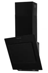
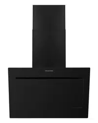
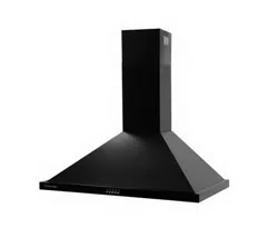
Operating modes
This appliance can be used in extraction-air mode or circulating air mode.
Extraction-air mode
The air which is drawn in is cleaned by the grease filters and extracted outside by a hose.
Important Notes:
• The extracted air must not be extracted into a functioning smoke, exhaust gas flue or into a shaft which is used to ventilate installation rooms which contain heat-producing appliances.
• Before the extracted air is extracted into a non-functioning smoke or exhaust gas flue, obtain the consent of the heating engineer responsible.
• If the extracted air is carried through the outer wall, a telescopic wall box should be used.
Circulating-air mode
The air which is drawn in is cleaned by the grease filters and a carbon filter (carbon filter is not supplied with your appliance) and extracted back into the kitchen.
Important Note: To remove odours in circulating-air mode, you must install a carbon filter (carbon filter is not supplied with your appliance) . Please contact Product Care or visit the Russell Hobbs website to purchase carbon filter. Dependent on use it is recommended that a carbon filters are changed every 2 – 3 months.
Installation
Preparation
Ensure that there are no electric wires, gas or water pipes in the area where holes are to be made.
1. Ensure that there is an electrical plug socket within adequate distance of the hood after it has been installed.
2. Mark a vertical centre line on the wall from the ceiling to the worktop in the centre of the area that the cooker hood is to be fitted.
3. Mark 3 horizontal lines on the wall in the following positions:
- A. A horizontal line A at 970 – 1070 mm above the cooker top
- B. A horizontal line B at X mm above the horizontal line A.
- C. A horizontal line C at a 243 mm below the horizontal line A .
4. Mark the positions for the screws and the contour of the attachment area. Always ensure that the marks are level with a spirit level.
- 1. Mark 2 points (1) on the horizontal line A, 80 mm either side of the vertical reference line.
- 2. Mark 2 points (2) on the horizontal line B, 60 mm either side of vertical reference line.
- 3. Mark a point (3) on the horizontal line C, 100 mm either side of vertical reference line.
5. Drill holes at the marked points and insert the wall plugs:
- 1. 3 x 10mm Ø holes to a depth of 50mm for the hood fixing bracket and press the wall plugs flush with the wall. Horizontal line A.
- 2. Drill 2 x 10mm Ø holes to a depth of 50mm for the wall mounted flue duct fixing bracket and press the wall plugs flush with the wall (at the appropriate height and will depend on the height of the ceiling). Horizontal line B.
- 3. Drill 2 x 10mm Ø holes to a depth of 50mm for the safety screws. Horizontal line C.
6. Screw on the hood and wall mounted flue duct fixing brackets with the large screws.
Constructing and aligning the appliance.
Components inside the appliance may have sharp edges. Wear protective gloves
1. Partially remove the protective film from the back of the appliance.
2. Hook the appliance on to the hood fixing bracket (ensure the hood is fully hooked onto the hood fixing bracket, as the hooks on the bracket are stepped) and check that it is level with a spirit level.
3. Remove the appliance from the hood fixing bracket and following installation, remove the film completely.
4. Attach the lower (bigger) flue duct to the appliance and secure it at the rear of the appliance (at the bottom) with 2 small screws. At the top of the lower (bigger) flue duct secure the flue ducting bracket to the duct with 2 small screws at the rear.
Attaching the appliance
Components inside the appliance may have sharp edges. Wear protective gloves.
1. Slide the upper (smaller) flue duct into the lower (bigger) flue duct.
2. Carefully mount the appliance onto the hood fixing bracket (ensure the hood is fully hooked onto the hood fixing bracket, as the hooks on the bracket are stepped).
3. Remove the aluminium filters from the underside of the hood (see page 19) and fix 2 large screws into bottom part of the hood and into the wall plugs (the wall plugs that are installed on line C on page 11). Reattach the filters.
4. Place the hose on the duct outlet.
5. Slide the upper flue duct upwards and screw it to the sides of the wall mounted flue duct fixing bracket previously installed using 2 small screws.
6. Plug the hood into the electrical plug socket and turn on the socket.
Note: Align the flue duct before tightening the screws.
Ducted air exhaust system
• When installing the ducted version, connect the hood to the chimney using either a flexible or rigid pipe ɸ 150 mm or ɸ 120 mm. The product is supplied with a ɸ 150 mm flexible pipe therefore to install a ɸ 120 mm air exhaust connection a reducer flange (not supplied) will need to be attached to the outlet on the hood.
• Fix the ɸ 150 mm flexible pipe in position using sufficient pipe clamps (not supplied).
Note: Align the flue duct before tightening the screws. The has to be a 2 degree decline in the exhaust pipe to the outside vent
Usage
Note: Switch on the extractor hood when you start cooking and switch it off again several minutes after you have finished cooking. This is the most effective way of removing the kitchen fumes.
Control panel
Power
Press the power button to turn on the appliance, the fan will power on and the speed set to 1. The digital display will show 1. Press the power button to stop the fan and power off the appliance.
Note: after fan operation the fan will continue to run at low speed for approximately 3 minutes, even if the power button has been used to turn off the appliance.
Plus
Press the plus button to increase the extraction rate/fan speed that is required the appliance has 4 settings/speeds). Press the power button to stop the fan.
Minus
Press the minus button to decrease the extraction rate/fan speed that is required the appliance has 4 settings/speeds). Press the power button to stop the fan.
Light
The lighting can be turned on and off independently of the power and the fan setting/speed. Press the light button once to turn the lights on and then again to turn the lights off.
Cleaning and Maintenance:
Important notes:
- The appliance will become hot during operation, especially near the bulbs. Allow the appliance to cool down before cleaning.
- Penetrating moisture may result in an electric shock. Clean the appliance using a damp cloth only. Before cleaning, pull out the mains plug or switch off the circuit breaker in the fuse box.
- Do not use any high-pressure cleaners or steam cleaners, which can result in an electric shock.
- Components inside the appliance may have sharp edges. Wear protective gloves.
How to clean
Observe the information in the table on the following page to ensure that the different surfaces are not damaged by using the wrong type of cleaning agent. Do not use:
- Harsh or abrasive cleaning agents,
- Cleaning agents with a high concentration of alcohol,
- Hard scouring pads or sponges,
- High-pressure cleaners or steam cleaners.
Wash new sponge cloths thoroughly before use.
Follow all instructions and warnings included with the cleaning agents.
Aluminium grease filters:
Removing and installing the Aluminium grease filters:
Removing
1. Press the lock in and pull down the aluminium grease filter.
2. Take the filter out of the holder.
3. Clean the filter and allow to dry before replacing (refer to cleaning instructions on the following page).
Installing
1. Insert the aluminium grease filter by aligning the 2 metal tabs into the filter holder.
2. Press the lock in and push the filter upwards, locking it in place.
Carbon filters (must be purchased separately):
Installing the Carbon grease filters:
1. Remove the Aluminium filter(s) from the hood.
2. You will now be able to access the motor, carefully attached the carbon filters to both ends of the motor.
3. Carbon filters should be replaced after approximately 2-3 months of use.
4. The carbon filters cannot be washed or recycled.
Important notes
• Grease deposits in the grease filter may catch fire.
• Clean the grease filter at least every 2 months.
• Never operate the appliance without the grease filter.
• Do not use any aggressive, acidic or alkaline cleaning agents.
• When cleaning the aluminium grease filters, also clean the holder filters in the hood using a damp cloth (ensure the hood is turned off).
• The filters can be cleaned in the dishwasher or by hand.
Dishwasher:
1. Do not clean heavily soiled metal mesh grease filters together with utensils.
2. Place the aluminium grease filters loosely in the dishwasher.
3. The filters must not be wedged in.
4. The temperature should be 60ºC or less Note: If the filters are cleaned in the dishwasher, slight discolouration may occur. This has no effect on the function of the metal mesh grease filters.
By hand:
1. Soak the aluminium grease filters in a hot soapy water.
2. Clean the filters with a brush before rinsing them thoroughly.
3. Leave the filters to drain and put them back in to the hood when dry.
Replacing the light modules
• You cannot replaced the light bulbs, the entire light module has to be replaced.
• When changing the light modules, the contacts are live.
• Before changing the light module(s), unplug the appliance from the mains or switch off the circuit breaker in the fuse box.
• Only use a light module that is the same type and same power (details below), please contact customer services on 0345 208 8750 or visit mda.russellhobbs.com
1. Remove the grease filter and carefully remove the rear panel (a cross headed screwdriver will be needed to remove the screws from the front plate).
2. Unclip the light module from its terminal
3. Remove the light from the its fitting in the panel by pushing downwards so it pops through the panel (this may require pressure or force to be applied).
4. Put the replacement light module into the fitting (ensuring the terminal is threaded through the fitting) and connect it to the terminal.
5. Replace the panel (a cross headed screwdriver will be needed to fasten the screws into the front plate) and plug the appliance back into the mains or switch on the circuit breaker in the fuse box.