Loading ...
Loading ...
Loading ...
8
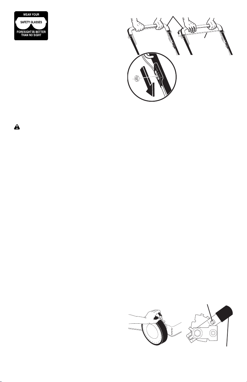
DRIVE CONTROL ADJUSTMENT
Over time, the drive control system may
become “loose”, resulting in decreased
speed. There are holes in the drive
control housing to increase tension on the
drive cable. Pro ceed as follows:
1. Turn unit off and disconnect spark plug
wire from spark plug.
2. Loosen nut, move drive control hous-
ing down handle to the next hole and
retighten nut.
3. Operate mower to test drive speed.
4. If condition fails to improve after the
above steps (forward speed remains
the same), your drive belt is worn and
should be re placed.
TO ADJUST CUTTING HEIGHT
Raise wheels for low cut and lower wheels
for high cut, adjust cutting height to suit
your requirements. Me di um position is
best for most lawns.
• To change cutting height, squeeze ad-
juster lever to ward wheel. Move wheel
up or down to suit your re quire ments. Be
sure all wheels are in the same setting.
NOTE: Adjuster is properly positioned
when plate tab inserts into hole in lever.
Also, 9-position adjusters (if so equipped)
allow lever to be positioned between the
plate tabs.
The operation of any lawn
mower can result in foreign
objects thrown into the
eyes, which can result in
severe eye damage. Always
wear safety glasses or eye shields while
operating your lawn mower or performing
any ad just ments or repairs. We recom-
mend a standard safety glasses or wide
vision safety mask worn over spectacles.
HOW TO USE YOUR LAWN MOWER
ENGINE SPEED
The engine speed was set at the factory
for optimum performance. Speed is not
adjustable.
ENGINE ZONE CONTROL
CAUTION: Federal regulations re quire
an engine control to be installed on this
lawn mower in order to minimize the
risk of blade contact injury. Do not un der
any circumstances attempt to de feat the
func tion of the operator con trol. The blade
turns when the engine is running.
• Your lawn mower is equipped with an
operator pres ence control bar which
requires the operator to be positioned
behind the lawn mower handle to start
and operate the lawn mower.
DRIVE CONTROL
• Self-propelling is controlled by hold-
ing the operator presence control bar
down to the handle and pulling the drive
control
bar up to the handle. The closer
to the handle the bar is pulled, the faster
the unit will travel.
• Forward motion will stop when either
the operator presence control bar or
drive control bar are released. To stop
forward motion without stop ping engine,
re lease the drive control bar only. Hold
op er a tor presence control bar down
against handle to con tin ue mowing
without self-propelling.
NOTE: If after releasing the drive control
the mower will not roll backwards, push
the mower forward slightly to disengage
drive wheels.
• To keep drive control engaged when
turning corners, push down on the
handle to lift the front wheels off the
ground while turning lawn mower.
LEVER BACKWARD
TO LOWER MOWER
LEVER FORWARD TO RAISE MOWER
Plate tab
Lever
DRIVE
CONTROL
ENGAGED
Drive
control bar
DRIVE
CONTROL
DISENGAGED
Operator presence control bar
TO ADJUST,
MOVE DOWN
TO NEXT HOLE
37
CRAFTSMAN ROTARY LAWN MOWER - - MODEL NUMBER 917.376152
KEY PART
NO. NO. DESCRIPTION
KEY PART
NO. NO. DESCRIPTION
1 194200X479 Upper Handle
2 183567 Engine Zone Control Cable
3 850733X004 Bracket, Upstop
4 166649 Mulcher Plug
5 66426 Wire Tie
6 189713X428 Handle Knob
7 750634 Screw
8 194199X428 Control Bar
9 193679 Rear Door Assembly (Includes Springs)
10 128415 Pop Rivet
11 150050 Screw, Self-Tapping #10-24 x 5/8
12 54583 Screw, Hex Hex Head, Sems 1/4-20 x 1/2
14 195622X479 Back Plate
15 700365X479 Side Baffle
16 176655X479 Discharge Baffle
17 140661X479 Rear Baffle
18 132004 Keps Locknut 1/4-20
19 194788 Rope Guide
20 189008 Rear Skirt
21 170938 Spring, Rear Door, LH
24 170939 Spring, Rear Door, RH
25 83923 Nut, Hex, Flanged
26 184193 Bolt, Rear Door
27 193909X460 Wheel & Tire Assembly, Rear
28 142748 Bolt, Shoulder 3/8-16 x 1
29 62335 Washer, Belleville
30 145935X004 Axle Arm Assembly
31 701037 Selector Knob
32 700331X004 Selector Spring
33 189917X428 Mulcher Door
34 146630 Spacer
35 133757X007 Wheel Adjusting Bracket, RH
36 175735 Hinge Bracket Assembly
37 150078 Screw, Sems, Thread Cutting 5/16-18 x 3/4
38 402574X428 Discharge Deflector
39 195916X479 Handle Bracket Assembly, LH
40 195917X479 Handle Bracket Assembly, RH
41 150406 Screw, Hex Head, Threaded, Rolled 3/8-16 x 1-1/8
42 193000 Spring, Torsion
43 73800400 Nut, Hex, Nylock
44 192613 Kit, Lawn Mower Housing
(Includes Key Numbers 14, 15 and 51)
45 175650 Rod, Hinge
46 194037 Blade Adapter / Pulley
47 141114 Blade, 22"
48 851074 Washer, Hardened
49 850263 Washer, Helical
50 851084 Screw, Machine, Hex Head 3/8-24 x 1-3/8 Grade 8
51 170031 Kit, Front Baffle (Includes Key Number 53)
52 404763 Danger Decal
53 17600406 Screw, Serrated, Type TT 1/4-20
55 751592 Nut, Hex 3/8-16
56 88652 Hinge Screw 1/4-20 x 1-1/4
57 51793 Hairpin Cotter
58 151590X479 Lower Handle
59 191574 Handle Bolt
61 188839X004 Mounting Bracket, Debris Shield
62 199314 Debris Shield
63 192325 Screw, Debris Shield
64 - - - Engine, Briggs & Stratton, Model Number
125K02-0658-E1 (See Breakdown)
68 133759X007 Wheel Adjusting Bracket, LH
69 197991 Clip, Cable
72 182227 Screw
73 197162 Belt Keeper
74 182228 Nut, Hex
- - 404764 Warning Decal (not shown)
- - 405426 Owner’s Manual (English / Spanish)
Available accessories not included with lawn mower:
- - 71 33623 Gas Can (2.5 Gallon Container)
- - 71 33500 Fuel Stabilizer
- - 71 33000 SAE 30W Oil (20 Ounce Bottle)
NOTE: All component dimensions given in U.S. inches. 1 inch = 25.4 mm.
IMPORTANT: Use only Original Equipment Manufacturer (O.E.M.) replacement parts. Failure to do so could be hazardous, damage your lawn mower and void your warranty.
Loading ...
Loading ...
Loading ...