
®
MODEL NUMBER 917.259564 OWNER'S MANUAL
e Assembly
Operation
®Customer Responsibilities
Service and Adjustments
Repair Parts
CAUTION: Read and follow all safety rules and instructions before operating this equipment.
FOR CONSUMER ASSISTANCE HOT LINE, CALL THIS TOLL FREE NUMBER: 1-800-659-5917
IIIIIIIIIII!111111111111111111111111111IIIIIIIIIII III IIIII IIIIIIIIIIIIIIIIIII
............ , ............. , ,, ,
SAFETY RULES
Safe Operation Practices for Ride-On Mowers
IMPORTANT: THIS CUTTING MACHINE iS CAPABLE OF AMPUTATING HANDS AND FEET AND THROWING OBJECTS
FAILURE TO OBSERVE THE FOLLOWING SAFETY iNSTRUCTIONS COULD RESULT iN SERIOUS INJURY OR DEATH.
I, GENERAL OPERATION
• Read, understand, and follow all instructions in the manual
and on the machine before starting.
• Only allow responsible adults, who are familiar with the
instructions, to operate the machine°
• Clear the area of objects such as rocks, toys, wire, etc.,
which could be picked up and thrown by the blade.
• Be sure the area is clear of other people before mowing° Stop
machine if anyone enters the ama_
• Never carry passengers
• Do not mow in reverse uniess absolutely necessary. Always
look down and behind before and while backing.
• Be aware of the mower discharge direction and do not point
it at anyone. Do not operate the mower without either the
entire grass catcher or the guard in place.
• Slow down before turning.
° Never leave a running machine unattended. Always turn off
blades, set parking brake, stop engine, and remove keys
before dismounting_
• Turn off blades when not mowing_
• Stop engine before removing grass catcher or unclogging
chute.
• Mow only in daylight or good artificial light.
• Do not operate the machine while under the influence of
alcohol or'drugs°
• Watch for traffic when operating near or crossing roadways.
• Use extra care when loading or unloading the machine into
a trailer or truck.
I!. SLOPE OPERATION
Slopes are a major factor related to loss-of-control and
tipover accidents, which can result in severe injury or
death_ Afl slopes require extra caution. If you cannot back
up the slope or if you feel uneasy on it, do not mow it
DO:
o Mow up and down slopes, not across.
° Remove obstacles such as rocks, tree limbs, etc.
° Watch for holes, ruts, or bumps_ Uneven terrain could
overturn the machine. Tall grass can hide obstacles
° Use slow speed, Choose a low gear so that you wiltnot have
to stop or shift while on the slope.
• Follow the manufacturer's recommendations for wheel
weights or counterweights to improve stability.
,, Use extra care with grass catchers or other attachments.
These can change the stability of lhe machine.
• Keep all movement on the slopes slowand gradual Do not
make sudden changes in speed or direction.
• Avoid starting or stopping on a slope, if tires lose traction,
disengage the blades and proceed slowly straight down the
slope.
DO NOT:
• Do not tum on slopes unless necessary, and then, turnslowly
and gradually downhill, if possible°
• Do not mow near drop-offs, ditches, or embankments_ The
mower could suddenly turn over if a wheel is over the edge
of a ctiff or ditch, or if an edge caves in.
• Do not mow on wet grass. Reduced traction could cause
sliding,
• Do not tryto stabilize the machine by putting your foot on the
ground.
• Do not use grass catcher on steep slopes.
IlL CHILDREN
Tragic accidents can occur if the operator is not alert to the
presence of children. Chitdren are often attracted to the
machine and the mowing activity Never assume that
children will remain where you last saw them.
• Keep children out of the mowing area and under the watchful
care of another responsible adulL
• Be alert and turn machine off if chiEdren enter the area
• Before and when backing, took behind and down for small
children.
• Never carry children. They may fall off and be seriously
injured or interfere with safe machine operation.
. Never allow children to operate the machlneo
° Use extra care when approaching blind corners, shrubs,
trees, or other objects that may obscure vision
IV. SERVICE
• Use extra care in handling gasoline and other fuels They are
flammable and vapors are explosive°
Use only an approved container
Never remove gas cap or add fuel with the engine
running. Allow engine to cool before refueling, Do not
smoke,
Never refuel the machine indoors.
Never store the machine or fuel container inside where
there is an open flame, such as a water heater
• Never run a machine inside a closed area.
• Keep nuts and boits, especially blade attachment bolts, tight
and keep equipment in good condition.
• Never tamper with safety devices_ Check their proper
operation regularly.
• Keep machine free of grass, leaves, or other debris build-up.
Clean oi! or fuel spiilage Allow machine to cool before
storing
• Stop and inspect the equipment if you strike an object.
Repair, if necessary, before restarting,
• Never make adjustments or repairs with the engine running
• Grass catcher components are subject to wear, damage, and
deterioration, which could expose moving parts or aIIow
objects to be thrown. Frequently check components and
reptace with manufacturer's recommended parts, when nec-
essary.
• Mower blades are sharp and can cut, Wrap the blade(s) or
wear gloves, and use extra caution when servicing them.
• Check brake operation frequently. Adjust and service as
required.
i ii iii ii i
!
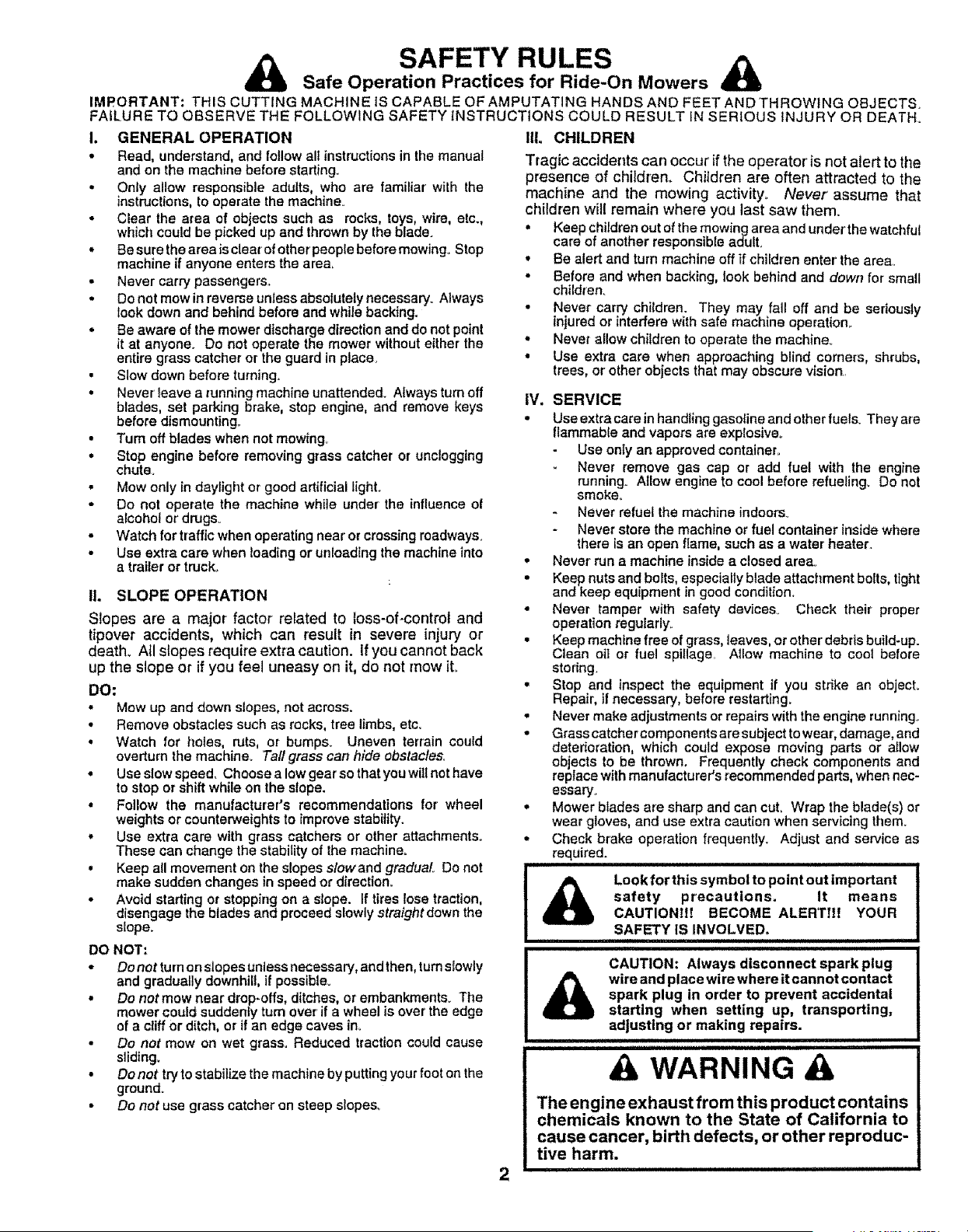
Look forthis symbol to point out important
safety precautions_ It means
CAUTIONtf! BECOME ALERTIH YOUR
SAFETY IS INVOLVED. ......
CAUTION: Always disconnect spark plug
wire and place wire where it cannot contact
spark plug in order to prevent accidental
starting when setting up, transporting,
adjusting or making repairs.
A WARNING A
The engine exhaust from this product contains
chemicals known to the State of California to
cause cancer, birth defects, or other reproduc-
tive harm.

CONGRATULATIONS on your purchase of a Sears
Tractor,, It has been designed, engineered and manufac-
tured to give you the best possible dependability and
performance.
Should you experience any problem you cannot easily
remedy, please contact your nearest Sears Authorized
Service CentedDepartment,, We have competent, welF
trained technicians and the proper tools to service or repair
this tractor,,
Please read and retain this manual The instructions will
enable you to assemble and maintain your tractor properly°
Always observe the "SAFETY RULES"°
MODEL
NUMBER 917.259564
SERIAL
NUMBER
DATE OF PURCHASE
THE MODELAND SERIAL NUMBERS WILL BE FOUND
ON A PLATE UNDER THE SEAT,,
YOU SHOULD RECORD BOTH SERIAL NUMBER AND
DATE OF PURCHASE AND KEEP IN A SAFE PLACE
FOR FUTURE REFERENCE°
MAINTENANCE AGREEMENT
A Sears Maintenance Agreement is available on this prod-
ucL Contact your nearest Sears store for details,
CUSTOMER RESPONSIBILITIES
• Read and observe the safety rules.
• Fo!low a regular schedule in maintaining, caring for and
usEng your tractor°
o Follow the instructions under "Customer Responsibili-
ties" and "Storage" sections of this owner's manual.
WARNING: This tractor is equipped with an internal
combustion engine and should not be used on or near any
unimproved forest-covered, brush-covered or grass-cov-
ered land unless the engine's exhaust system is equipped
PRODUCT SPECiFiCATiONS
HORSEPOWER: 1&5
GASOLINE CAPACITY 35 GALLONS
AND TYPE: UNLEADED REGULAR
OIL TYPE (API-SF/SG/SH): SAE 30 (above 32°F)
SAE 5W-30 (below 32°F)
OIL CAPACITY: W/FILTER: 3.5 PINTS
W/O FILTER: &0 PINTS
SPARK PLUG: CHAMPION RC12YC
GAP: °030")
VALVE CLEARANCE: INTAKE: .004" - ..006"
EXHAUST: .004" - .006"
GROUND SPEED (MPH): FORWARD:
1st 1.1
2nd 1 5
3rd 23
4th 35
5th 4.4
6th 5.7
REVERSE: 1,7
TfRE PRESSURE: FRONT: 14 PSI
REAR: 10 PSi
CHARGING SYSTEM: 16 @ 3600 RPM
BATTERY: AMP/HR: 30
MIN. CCA: 240
CASE SIZE: UIR
BLADE BOLT TORQUE: 30-35 FT',,LBS_
with a spark arrester meeting applicable local or state laws
(if any),, If a spark arrester is used, it should be maintained
in effective working order by the operator.,
In the state of California the above is required by taw
(Section 4442 of the Cafifornia Public Resources Code).
Other states may have similar laws. Federal laws apply on
federal lands. A spark arrester for the muffler is available
through your nearest Sears Authorized Service Center!
Department (See REPAIR PARTS section of this manual)°
i ...... ii,,-u= =,, ,...... i iii1,,=1111 ,H lu,=,
LiMiTED TWO YEAR WARRANTY ON CRAFTSMAN RiDiNG EQUIPMENT
For two (2) years from the date of purchase, if this Craftsman Riding Equipment is maintained, lubricated and tuned up according
to the instructions in the owner's manual, Sears will repair or replace, free of charge, any parts found to be defective in material or
workmanship
This Warranty does not cover:
° Expendable items which become worn during normal use, such as blades, spark plugs, air cleaners, belts, etc.
• Tire replacement or repair caused by punctures from outside objects, such as nails, thorns, stumps, or glass,
° Repairs necessary because of operator abuse, negligence, improper storage or accident or the failure to maintain the
equipment according to the instructions contained in the owner's manual.
o Riding equipment used for commercial or rental purposes.
UMITED 90 DAY WARRANTY ON BATTERY
For ninety (90) days from date of purchase, if any battery included with this riding equipment proves defective in material or
workmanship and our testing determines the battery will not hold a charge, Sears will replace the battery at no charge.
IN-HOME WARRANTY SERVICE ON YOUR CRAFTSMAN RIDING EQUIPMENT IS AVAILABLE AT NO-CHARGE FOR 30
DAYS FROM THE DATE OF PURCHASE. PLEASE CONTACT YOUR NEAREST SERVICE CENTER. AFTER 30 DAYS FROM
THE DATE OF PURCHASE, WARRANTY SERVICE IS AVAILABLE BY TAKING YOUR CRAFTSMAN RIDING EQUIPMENT TO
YOUR NEAREST SEARS SERVICE CENTER. (IN-HOME WARRANTY SERVICE WILL ST_LL BE AVAILABLE AFTER 30 DAYS
FROM THE DATE OF PURCHASE BUT A STANDARD TRIP CHARGE WILL APPLY.) THIS WARRANTY APPLIES ONLY
WHILE THIS PRODUCT IS IN THE UNITED STATES..
This Warranty gives you specific legal rights, and you may also have other rights which may vary from state to state.
SEARS, ROEBUCK AND CO., D/817 WA, HOFFMAN ESTATES, IL 60179
,,,u ..... u,
3
TABLE OF CONTENTS
SAFETY RULES ............................................................ 2
PRODUCT SPECIFICATIONS ...................................... 3
CUSTOMER RESPONSIBILITIES ..................... 3, 15-19
WARRANTY .................................................................. 3
TABLE OF CONTENTS ................................................ 4
INDEX ............................................................................ 4
TRACTOR ACCESSORIES .......................................... 5
ASSEMBLY ................................................................ 7-9
OPERATION ........................................................... 10-14
MAINTENANCE SCHEDULE ...................................... 15
SERVICE AND ADJUSTMENTS ..... ,...................... 20-25
STORAGE ................................................................... 26
TROUBLESHOOTING ............................................ 27-28
REPAIR PARTS - TRACTOR ................................. 30-47
REPAIR PARTS - ENGINE .................................... 48-53
PARTS ORDERING/SERVICE .................. BACK PAGE
NDEX
A
Accessories ...................................................5
Adjustments:
Brake ...................................................22
Carburetor ........................................ 25
Mower"
Front-To-Back ........................ 21
Side-To-Side ......................... 21
Throttle Control Cable ................. 24
Air Filter, Engine ..................................... 18
Air Screen, Engine ................................. 18
Assembfy ............................................. 7-9
B
Battery:
Charging ..........................................7-8
Cleaning ..............................................t 7
Connecting ......................................7-8
Starting with Weak Battery ........ 23
Storage ..............................................26
Terminals .................................... 17
Belts:
Motion Drive
Removal/Replacement ............ 22
Mower Blade Drive
Removal/Replacement .............22
Blade:
Sharpening .................................. 16
Replacement .......................................16
Brake Adjustment .................................. 22
C
Carburetor Adjustment ........................ 25
Controls, Tractor ................................... 11
Customer Responsibilities ............... 15- t 9
Engine:
AirFiller......................................... 18
Air Screen, Engine .................... 18
Battery ...........................................17
Coofing Fins, Engine ................. 18
Engine 0_1.....................................17
FuelFilter.....................................19
Spark Plugs...................................19
Tractor:
Blades ...................................... t6
Lubrication Chart ..................... 15
Maintenance Schedule ........... 15
Tire Care ...................................8,16,23
Cutting Height, Mower ...........................12
E
Electricat:
Interlocks and Relays ................... 24
Schematic .......................................29
Wiring Diagram ........................... 30
Engine:
Air Filter ........................................... 18
Air Screen .................................. 18
Cooling Fins, Engine ...................... 18
Oil Change .........................................17
Oil Level ........................................13,17
OilType .............................................17
Preparation ................................... 13
Repair Parts ............................ 48-53
Starting ............................................14
Storage ........................................ 26
F
Filters:
Air................................................18
Fuel .......................................... 19
Fuel:
Type .............................................. 13
Storage ..................................... 26
Fuse .................................................... 24
G
Gauge Wheels .............................................8
H
Hood Removal/installation ................ 24
L
Leveling Mower Deck ...................... 21
Lubrication Chart .....................................15
M
Maintenance Schedule ..........................15
Mower:
Adjustment, Front-to-Back ......... 21
Adjustment, Side-to-Side .............. 21
Blade Sharpening ............................16
Blade Replacement ...................... 16
Cutting Height ............................... 12
Installation ....................................... 20
Operation ...................................... t3
Removal .................................................20
Mowing Tips ............................................ 14
Muffler.....................................................19
Spark Arrester ................................3,40
Muicher Plate ........................................... 9
4
O
Oil:
Cold Weather Conditions ....... !3,17
Engine ................................................17
Storage ..............................................26
Operation ............................................11-14
Operating Mower'. .................................. 13
Options:
Accessories ...................................... 5
Spark Arrester ............................. 3,40
P
Parking Brake ...........................................11-12
Parts Bag .................................................. 6
Parts, Replacement/Repair ........... 30-47
Product Specifications ............................. 3
R
Repair Parts ..................................... 30*47
S
Safety Rules ........................................... 2
Seat........................................................ 8
Service and Adjustments ................ 20-25
Brake .............................................. 22
Carburetor ...................................... 25
Fuse .............................................. 24
Hood Remova!/Installatien ........... 24
Motion Drive Belt
RemovaltReplacement .............22
Mower Blade Drive Belt
Removal/Replacement .......... 22
Mower Adjustment:
Front-to-Back ....................... 21
Side-to-Side .............................. 21
Mower Installation ....................... 20
Mower Removal ............................. 20
Tire Care ............................... 8,16,23
Slope Guide Sheet ................................ 55
Spark Plugs ...............................................19
Specifications ............................................ 3
Starting the Engine ........................ 13-14
Steering Wheel .......................................7,23
Stopping the Tractor .............................. 12
Storage .................................................. 26
T
Throttle Control Cable Adjustment ..... 24
Tires ..................................................8, ! 6,23
Trouble Shooting Chart ................... 27-28
Transaxie Repair Parts .................... 46-47
W
Warranty ..................................................... 3
Wiring Diag[am ..........................................30
Wiring Schematic ................................. 29
i i ....i i1.= .i........ i .. ..i ii .i ....
ACCE$SORmE$ AN ATTACHMENTS
..... i..., .... P... i. ,111 ..11 .. .HI. i
These accessories and attachments were available through most Sears retail outlets and service centers when the tractorwas purchased°
Most Sears stores can order these items for you when you provide the model number of your tractor
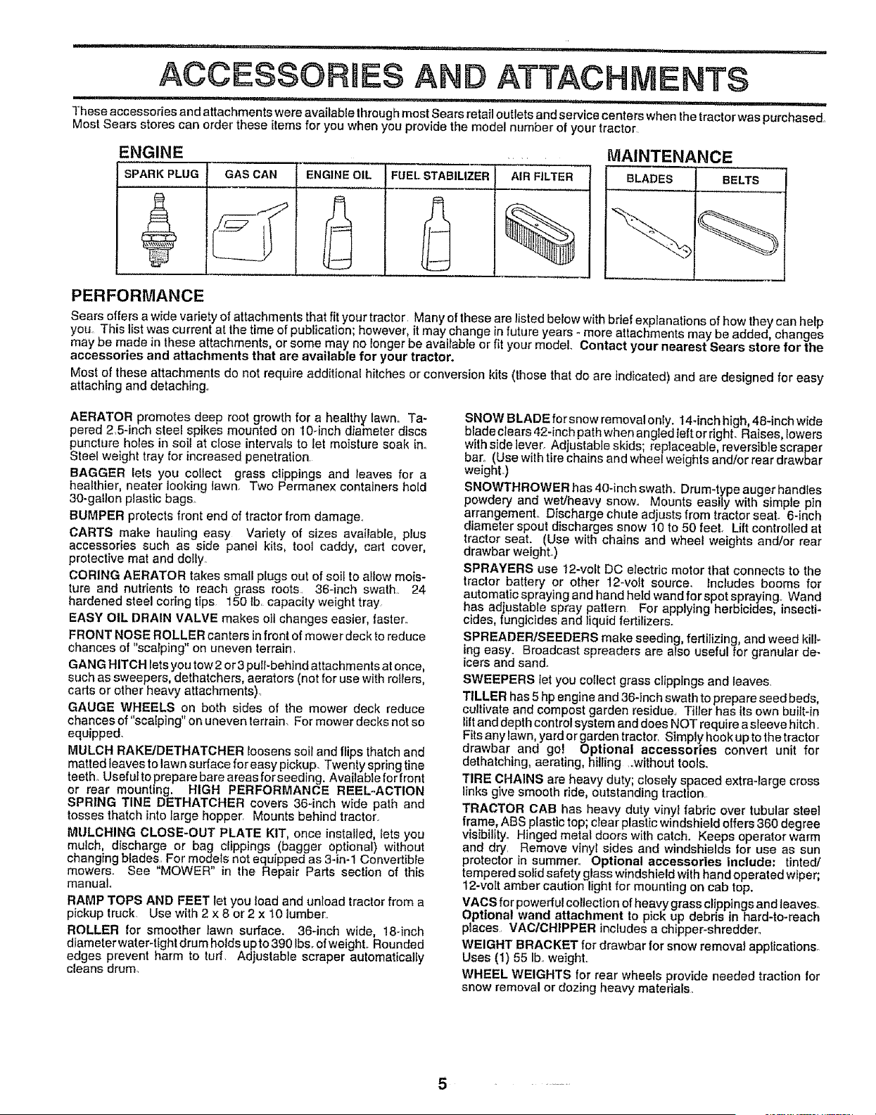
ENGINE
SPARK PLUG GAS CAN
ENGINE OIL FUEL STABILIZER
AIR FILTER
%
BLADES
MAINTENANCE
BELTS
PERFORMANCE
Sears offers a wide variety of attachments that fityour tractor Many of these are listed below with brief explanat ons of how they can help
you This list was current at the time of publication; however, it may change in future years - more attachments may be added, changes
may be made in these attachments, or some may no longer be available or fit your model Contact your nearest Sears store for the
accessories and attachments that are available for your tractor,
Most of these attachments do not require additional hitches or conversion kits (those that do are indicated) and are designed for easy
attaching and detaching..
AERATOR promotes deep root growth for a healthy lawn. Ta-
pered 2,5-inch steel spikes mounted on 10-inch diameter discs
puncture holes in soil at close intervals to let moisture soak ino
Steel weight tray for increased penetration.
BAGGER lets you collect grass clippings and leaves for a
healthier, nearer looking lawn. Two Permane× containers hold
30-gallon plastic bags_
BUMPER protects front end of tractor from damage.
CARTS make hauling easy Variety of sizes available, plus
accessories such as side panel kits, tool caddy, cart cover,
protective mat and doily
CORING AERATOR takes small plugs out of soil to allow mois-
ture and nutrients to reach grass roots. 36-inch swath.. 24
hardened steel coring tips 150 lb. capacity weight tray
EASY OIL DRAIN VALVE makes oil changes easier, taster.
FRONT NOSE ROLLER canters in front of mower deck to reduce
chances of "scalping" on uneven terrain
GANG HITCH lets you tow 2 or 3 pulbbehJnd attachments at once,
such as sweepers, dethatchers, aerators (not for use with rollers,
carts or other heavy attachments)..
GAUGE WHEELS on both sides of the mower deck reduce
chances of "scalping" on uneven terrain. For mower decks not so
equipped.
MULCH RAKE/DETHATCHER loosens soil and flips thatch and
matted leaves to lawn sudace for easy pickup. Twenty spring tine
teeth. Useful to prepare bare areas forseeding. Available for front
or rear mounting. HIGH PERFORMANCE REEL-ACTION
SPRING TINE DETHATCHER covers 36-inch wide path and
tosses thatch into large hopper. Mounts behind tractor.
MULCHING CLOSE-OUT PLATE KIT, once installed lets you
mulch, discharge or bag clippings (bagger optional) without
changing blades For models not equipped as 3-ira1 Convertible
mowers. See MOWER in the Repair Parts section of this
manual.
RAMP TOPS AND FEET let you load and unload tractor from a
pickup truck Use with 2 x 8 or2 x 10 lumber..
ROLLER for smoother lawn surface, 36-inch wide, 18-inch
diameter water-tight drum holds upto 390 Ibsoof weight.. Rounded
edges prevent harm to turf. Adjustable scraper automatically
cleans drum
SNOW BLADE forsnow removal only. 14*inch high, 48-inch wide
blade ciears 42-inch path when angled teft or right. Raises, Iowers
with side ]ever. Adjustable skids; replaceable, reversible scraper
bar° (Use with tire chains and wheel weights and/or rear drawbar
weight.)
SNOWTHROWER has 40-inch swath. Drum-type auger handles
powdery and wet/heavy snow.. Mounts easily with simple pin
arrangemenL Discharge chute adjusts from tractor seat. 6-inch
diameter spout discharges snow 10 to 50 feet. Lift controlled at
tractor seat. (Use with chains and wheel weights and/or rear
drawbar weight.)
SPRAYERS use 12-volt DC electric motor that connects to the
tractor battery or other 12-volt source, includes booms for
automatic spraying and hand held wand for spot spraying.r Wand
has adiustable spray pattern For applying herbicides insecti*
cides, fungicides and quid fertilizers.
SPREADER/SEEDERS make seeding, fertilizing, and weed kill,.
mg easy. Broadcast spreaders are also useful for granular de-
icers and sand.
SWEEPERS tet you coflect grass clippings and leaves
TILLER has 5 hp engine and 36-inch swath to prepare seed beds,
cultivate and compost garden residue.. Tiller has its own built-in
lilt and depth control system and does NOT require a sleeve hitch.
Fits any lawn, yard or garden tractor. Simply hook up to the tractor
drawbar and go! Optional accessories convert unit for
dethatching, aerating, hilling .°without tools.
TIRE CHAINS are heavy duty closely spaced extra-large cross
nks g ve smooth ride, outstanding traction.
TRACTOR CAB has heavy duty vinyl fabric over tubular steel
frame, At3S plastic top; clear plastic windshield oilers 360 degree
visibility. Hinged metal doors with catch. Keeps operator warm
and dry Remove vinyl sides and windshields for use as sun
protector in summer_ Optional accessories include: tinted/
tempered solid safety glass windshield with hand operated wiper
12-vott amber caut on ight for mounting on cab top.
VACS for powerful collection of heavygrass clippings and leaves.
Optional wand attachment to pick up debris in hard-to-reach
places VAC/CHIPPER includes a chipper-shredder.
WEIGHT BRACKET for drawbar for snow removal applications_
Uses (1) 55 Ib..weight..
WHEEL WEIGHTS for rear wheels provide needed traction for
snow removal or dozing heavy materials.
.......
L _ ' '1=u'= ..................... :.........
CONTENTS OF H. PACK
................... 1, u ruu,,,,m, HI =,=,unnn I
= I u,,,,,u,
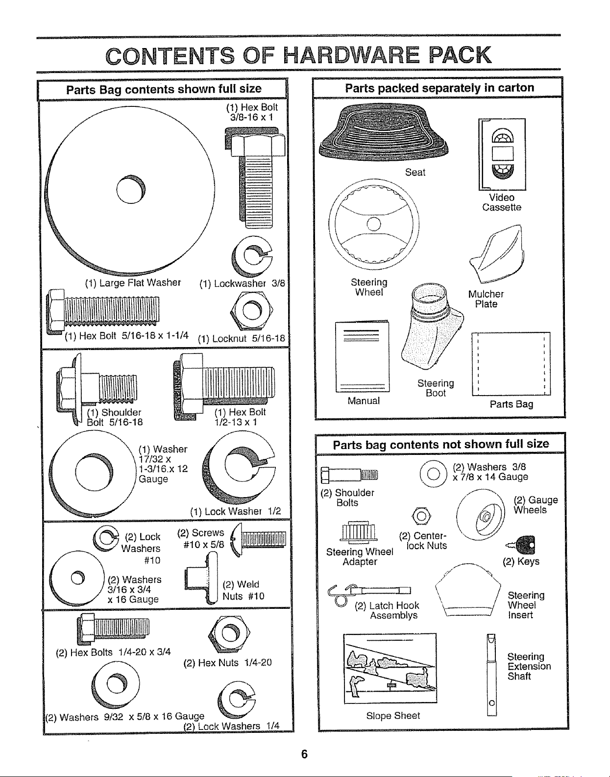
Parts Bag contents shown full size Parts packed separately in carton
i , ,i,, ii iiiiiiiiiiiiii i i ,, i i,i
i, = u '"H"
__ (1) HexBolt
3/8-1 6 x 1
1--
I
i
i
i
-_Jo
........................ =
i (1) Shoulder
i"JB01t 5/16-18
_\ (1) Washer
_ \ 17/32 x
t-31t6.x 12
Gauge
(t) Large Flat Washer (1) Lockwasher 318
_(t) Hex Bolt 5/16-18 x 1-1/4 (1) Locknut 5/16-18
'U'H
(1) Hex Boft
112-13 x 1
(1) Lock Washer 1/2
11 i,,11 ] , ,, III.M,I., 1,, ii1,1
(2) Lock (2) Screws _ ;_
wo,%
(_) (2)Washers t
_, / 3/16 x 3/4 (2) Weld
'_=,_ x16Gauge ,,, ,_ Nuts #10
(2) Hex Bolts 1/4-20 x 314
(2) Hex Nuts 1/4-20
(2) Washers 9/32 x 5/8 x 16 Gauge
.... (2) Lock Was!)ers 1/4
Steering
Wheel
Manual
Seat
Video
Cassette
_ Mulcher
Plate
I;
Steering
Boot
,,,i
Parts Bag
i i,, ,111,,1111,111,,111
........................... =i=, ,,,=,,,= i ul ,,,i,=
Parts bag contents not shown full size
............... ii i, i .... ii1,1,.1,1,,,I
('O_ (2)Washers 318
x 7t8 x 14 Gauge
(2) Shoulder
Bolts " '_ (2) Gauge
Q Wheels
(2) Center- •
lock Nuts
Steering Wheel
Adapter //_,_ (2) Keys
_o (I"k \ _ Steering
Assemblys _ / Wheellnsert
Slope Sheet
i1 .................
€?
Steering
Extension
Shaft
6
ii,ul, ,, , iiii, ,................
BLY
" ,i,,u i ii iii,
Your new tractor has been assembled at the factory with exception of those parts left unassembled for shipping purposes°
To ensure safe and proper operation of your tractor all parts and hardware you assembte must be tightened securely. Use
the correct tools as necessary to insure proper tightness_
TOOLS REQUIRED FOR ASSEMBLY
A socket wrench set will make assembly easier. Standard
wrench sizes are listed.
(1) 3/4" Socket w/drive rachet
(2) 7/t6" wrenches Phillips Screwdriver
(2) 1/2" wrench Tire pressure gauge
(t) 9/16" wrench Utility knife
When right or left hand is mentioned in this manual, it
means when you are in the operating position (seated
behind the steering wheel).
TO REMOVETRACTOR FROM CARTON
UNPACK CARTON
o Remove all accessible loose parts and parts cartons
from carton (See page 6).
o Cut, from top to bottom, along lines on all four corners
of carton, and lay panels flaL
o Check for any additional loose parts or cartons and
remove,,
BEFORE ROLLING TRACTOR OFF SKID
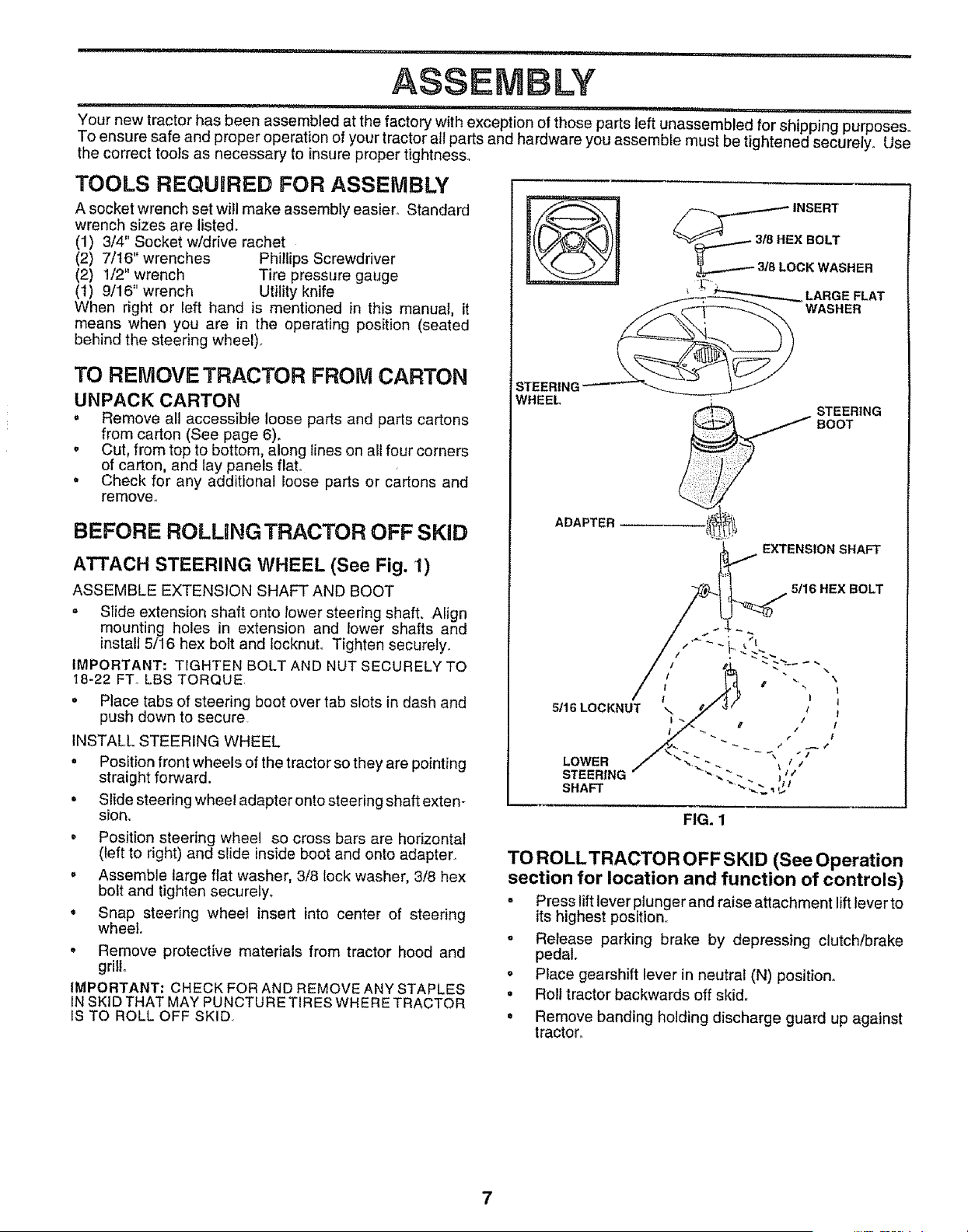
ATTACH STEERING WHEEL (See Fig. 1)
ASSEMBLE EXTENS!ON SHAFT AND BOOT
= Slide extension shaft onto lower steering shaft. Align
mounting holes in extension and lower shafts and
install 5/16 hex bott and locknuL Tighten securely.
IMPORTANT: TIGHTEN BOLT AND NUT SECURELY TO
I8-22 FT. LBS TORQUE
• Place tabs of steering boot over tab slots in dash and
push down to secure
INSTALL STEERING WHEEL
• Position front wheels of the tractor so they are pointing
straight forward.
= Slide steering wheel adapter onto steering shaft exten-
sion_
o Position steering wheel so cross bars are horizontal
(left to right) and slide inside boot and onto adapter.
= Assemble large flat washer, 3/8 lock washer, 3/8 hex
bolt and tighten securely,
. Snap steering wheel insert into center of steering
wheel.
o Remove protective materials from tractor hood and
grill
IMPORTANT: CHECK FOR AND REMOVE ANY STAPLES
IN SKID THAT MAY PUNCTURE TIRES WHERE TRACTOR
IS TO ROLL OFF SKID
____/8 INSERT
HEX BOLT
18 LOCK WASHER
LARGE FLAT
WASHER
STEERING
WHEEL
ADAPTER
EXTENSION SHAFT
5/16 HEX BOLT
FIG. 1
TO ROLLTRACTOR OFF SKID (See Operation
section for location and function of controls)
• Press liftlever plunger and raise attachment lift lever to
its highest position,,
o Release parking brake by depressing clutch/brake
pedal.
o Place gearshift lever in neutral (N) position.
• Roll tractor backwards off skid.
• Remove banding holding discharge guard up against
tractor°
7
iii ..................... ,l.lr,l,i ii .... i, L ....... lU I....... i"11 ....... ,n i1,,11,,
ASSEM LY
i
SEAT
HOW TO SET UP YOUR TRACTOR
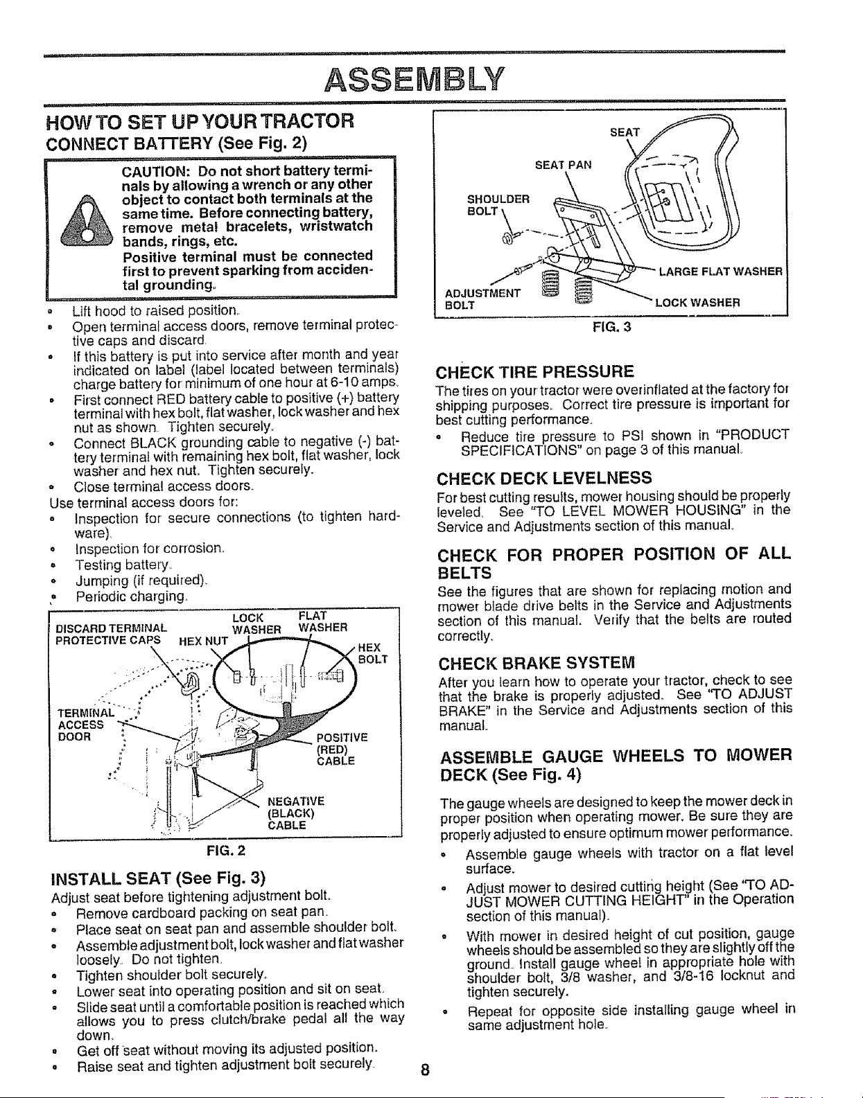
CONNECT BA'R'ERY (See Fig. 2)
CAUTION: Do not short battery termi-
nals by allowing a wrench or any other
object to contact both terminals at the
sametime. Before connecting battery,
remove metal bracelets, wristwatch
bands, rings, etc.
Positive terminal must be connected
first to prevent sparking from acciden-
tal grounding°
..... ,,, i
Lift hood to raised position,,
° Open terminal access doors, remove terminal protec-
tive caps and discard,
= If this battery is put into service after month and year
indicated on label (label located between terminals)
charge battery for minimum of one hour at 6-10 amp&
° First connect RED battery cable to positive (+) battery
terminal with hex bolt, fiat washer, lock washer and hex
nut as shown Tighten securely.
= Connect BLACK grounding cable to negative (-) bat-
tery terminaf with remaining hex bolt, flat washer, lock
washer and hex nut,, Tighten securely.
o Close terminal access doors.
Use terminal access doors for:
= Inspection for secure connections (to tighten hard-
ware),
. inspection for corrosion.
o Testing battery.
° Jumping (if required).
° Periodic charging.
DISCARD TERMINAL
PROTECTIVE CAPS HEX NUT
LOCK FLAT
WASHER WASHER
POSITIVE
(RED)
CABLE
FIG, 2
NEGATIVE
(BLACK)
CABLE
INSTALL SEAT (See Fig. 3)
Adjust seat before tightening adjustment boil
. Remove cardboard packing on seat pan.
. Place seat on seat pan and assemble shoulder bolt.
° Assemble adjustment boit, lock washer and ftat washer
loosely, Do not tighten.
o Tighten shoulder' bolt securely,_
* Lower seat into operating position and sit on seat.
° Slide seat until a comfortable position is reached which
allows you to press clutch/brake pedal all the way
down,,
. Get off Seat without moving its adjusted position,,
- Raise seat and tighten adjustment bolt securely.
SEATPAN
SHOULDER
BOLT \
FLAT WASHER
ADJUSTMENT
BOLT LOCKWASHER
FIG. 3
CHECK TIRE PRESSURE
The tires on you r tractor were overinftated at the factory for
shipping purpose& Correct tire pressure is important for
best cutting performance.
o Reduce tire pressure to PSI shown in "PRODUCT
SPECIFICATIONS" on page 3 of this manual,
CHECK DECK LEVELNESS
For best cutting resutts, mower housing should be properly
leveled, See "TO LEVEL MOWER HOUSING" in the
Service and Adjustments section of this manual
CHECK FOR PROPER POSITION OF ALL
BELTS
See the figures that are shown for replacing motion and
mower blade drive belts in the Service and Adjustments
section of this manual. Vedfy that the belts are routed
correctty_
CHECK BRAKE SYSTEM
After you learn how to operate your tractor, check to see
that the brake is properly adjusted. See '%0 ADJUST
BRAKE" in the Service and Adjustments section of this
manual
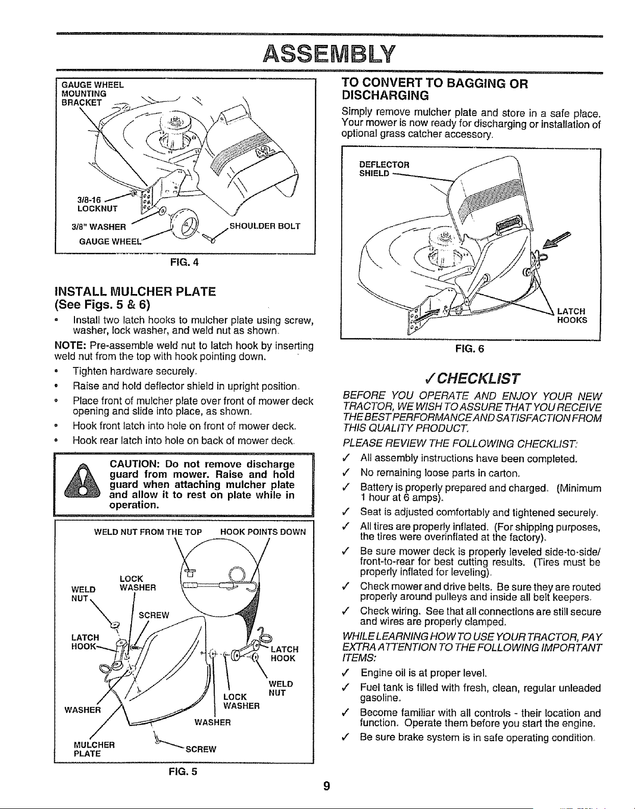
ASSEMBLE GAUGE WHEELS TO MOWER
DECK (See Fig. 4)
The gauge wheels are designed to keep the mower deck in
proper position when operating mower, Be sure they are
properly adjusted to ensure optimum mower performance.
= Assemble gauge wheels with tractor on a flat level
surface.
• Adjust mower to desired cuttirig height (See "TO AD-
JUST MOWER CUTTING HEIGHT' in the Operation
section of this manual).
o With mower in desired height of cut position, gauge
wheels should be assembled so they ate slightly off the
ground.. Install gauge wheel in appropriate hole with
shoulder bolt, 3/8 washer, and 3/8-16 Iocknut and
tighten securely.
• Repeat for opposite side installing gauge wheel in
same adjustment hole..
,,=,,,=,,,=,=,l , '"' ,,,,,,i,,, i
ASSEM LY
.... ii i1,,i,, , i,,,i,
TO CONVERT TO BAGGING OR
DISCHARGING
GAUGE WHEEL
MOUNTING
BRACKET \ _.
3/8-16
LOCKNUT
3_"WASHER
GAUGE WHEEL"
FIG. 4
SHOULDER BOLT
INSTALL MULCHER PLATE
(See Figs. 5 & 6)
= Install two latch hooks to mulcher plate using screw,
washer, lock washer, and weld nut as shown.
NOTE; Pre-assemble weld nut to latch hook by inserting
weld nut from the top with hook pointing down.
• Tighten hardware securely,
o Raise and hold deflector shield in upright position°
• Place front of mulcher plate over front of mower deck
opening and slide into place, as shown°
= Hook front latch into hole on front of mower deck.
= Hook rear latch into hole on back of mower deck
,_ CAUTION: Do not remove discharge
,_, _ guard from mower. Raise and hold
guard when attaching mulcher plate R
and allow it to rest on plate while in |
operation. ...................................
WELD NUT FROM THE TOP HOOK POINTS DOWN
LOCK
WELD WASHER
NUT\_x_._ SCREW
LATCH
WASHER
MULCHER
PLATE
LOCK
WASHER
FIG. 5
HOOK
WELD
NUT
9
Simply remove mutcher plate and store in a safe p_ace.
Your mower is now ready for discharging or installation of
optional grass catcher accessory,
DEFLECTOR
LATCH
HOOKS
FIG. 6
,f CHECKLIST
BEFORE YOU OPERATE AND ENJOY YOUR NEW
TRACTOR, WE WISH TO ASSURE THAT YOU RECEIVE
THE BEST PERFORMANCEAND SATISFACTION FROM
THIS QUALITY PRODUCT,
PLEASE REVIEW THE FOLLOWING CHECKLIST"
,/ All assembly instructions have been completed.
,/ No remaining loose parts in carton,
Battery is properly prepared and charged° (Minimum
t hour at 6 amps)o
v" Seat is adjusted comfortably and tightened securely.
v" All tires are properly inflated. (For shipping purposes,
the tires were ovednflated at the factory).
,/ Be sure mower deck is properly leveled side-to-side/
front-to-rear for best cutting results. (Tires must be
properly inflated for leveling)°
,/ Check mower and drive belts. Be sure they are routed
properly around pulleys and inside all belt keepers.
,/ Check wiring° See that all connections are still secure
and wires are properly clamped.
WHILE LEARNING HOW TO USE YOUR TRACTOR, PAY
EXTRA ATTENTION TO THE FOLLOWING IMPORTANT
ITEMS:
,/ Engine oil is at proper level.
,/ Fuel tank is filled with fresh, clean, regular unleaded
gasoline°
,/ Become familiar with all controls - their location and
function_ Operate them before you start the engine.
J Be sure brake system is in safe operating condition

i,unl ..... i lU, i,,nn i,,u,,nl,lU , i u u, Miiiiqnl"'i
OPERATION
................ i, ,i, u ii, ,,i rain I " ' lu u,n
These symbots may appear on your' tractor or in literature supplied with the product. Learn and understand their meaning.
BATTERY
ENGINE ON
CAUTION OR SLOW
WARNING
ENGINE OFF LIGHTS OFF
REVERSE FORWARD FAST
OIL PRESSURE CLUTCH LIGHTS ON
FUEL CHOKE
MOWER HEIGHT DIFFERENTIAL PARKING BRAKE
LOCK LOCKED
UNLOCKED
MOWER LIFT
REVERSE NEUTRAL
ATTACHMENT
CLUTCH ENGAGED
L
HIGH LOW
÷
ATTACHMENT
CLUTCH DISENGAGED
oS!
PARKING BRAKE
IGNITION
DANGER, KEEP HANDS AND FEET AWAY
HYDROSTATIC FREE WHEEL
(Hydro Models only)
10
,i,,i ..............
OPERATION
,11,,i i,i i i, ,,,,i i,
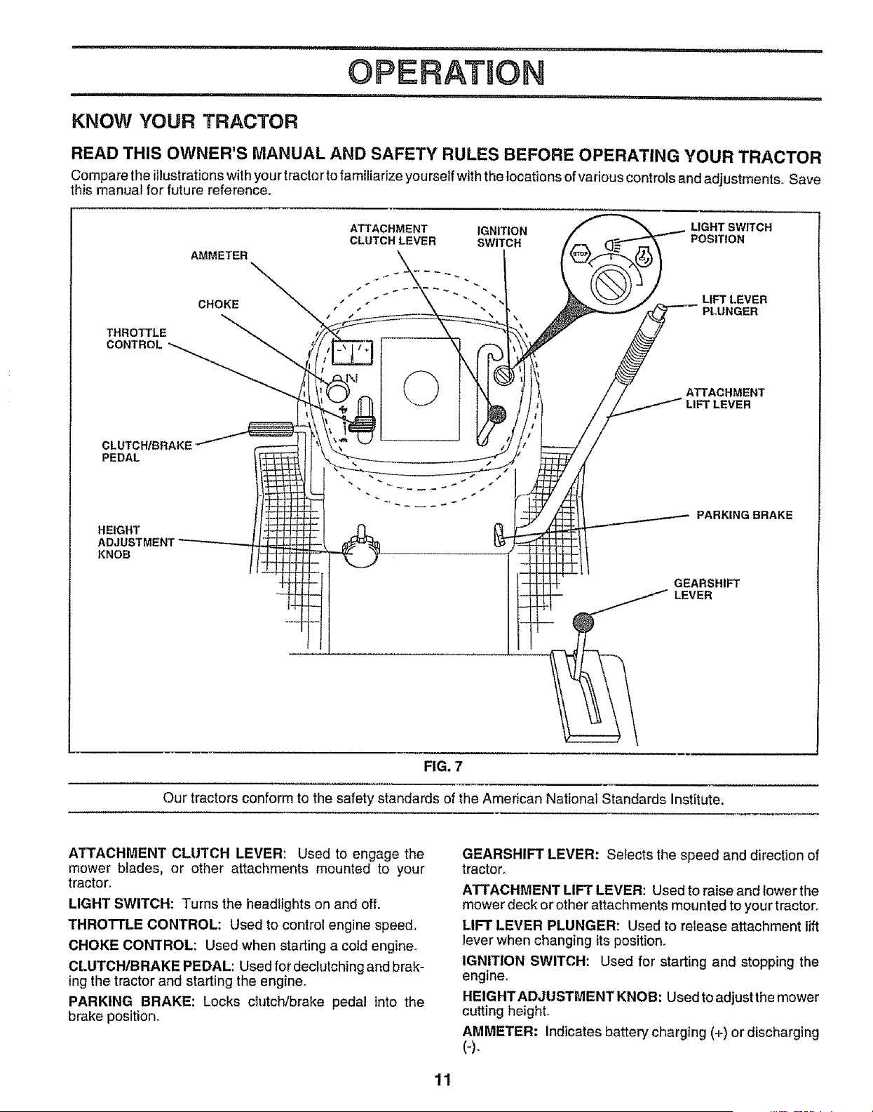
KNOW YOUR TRACTOR
READ THIS OWNER'S MANUAL AND SAFETY RULES BEFORE OPERATING YOUR TRACTOR
Compare the illustrationswith your tractor to familiarize yourself with the locations of various controls and adjustments. Save
this manual for future reference.
THROTTLE
CONTROL
ATTACHMENT IGNITION LIGHT SWITCH
CLUTCH LEVER SWITCH POSITION
AMMETER
CHOKE € t . " LIFT LEVER
• PLUNGER
ATTACHMENT
LIFT LEVER
CLUTCH/BRAKE
PEDAL
HEIGHT
ADJUSTMENT
KNOB
PARKING BRAKE
GEARSHIFT
LEVER
FIG. 7
Our tractors conform to the safety standards of the American National Standards Institute.
ATTACHMENT CLUTCH LEVER: Used to engage the
mower blades, or other attachments mounted to your
tractor.
LIGHT SWITCH: Turns the headlights on and off.
THRO'I-I'LE CONTROL: Used to control engine speed.
CHOKE CONTROL: Used when starting a cotd engine_
Ct.UTCHtBRAKE PEDAL: Used for declutching and brak-
ing the tractor and starting the engine.
PARKING BRAKE: Locks clutch/brake pedal into the
brake position°
GEARSHIFT LEVER: Selects the speed and direction of
tractor.
ATTACHMENT LIFT LEVER: Used to raise and lower the
mower deck or other attachments mounted to your tractor_
LIFT LEVER PLUNGER: Used to release attachment lift
lever when changing its positiono
IGNITION SWITCH: Used for starting and stopping the
engine.
HEIGHT ADJUSTMENT KNOB: Used to adjust the mower
cutting height.
AMMETER: indicates battery charging (+) or discharging
(-).
11
HOW TO USE YOUR TRACTOR
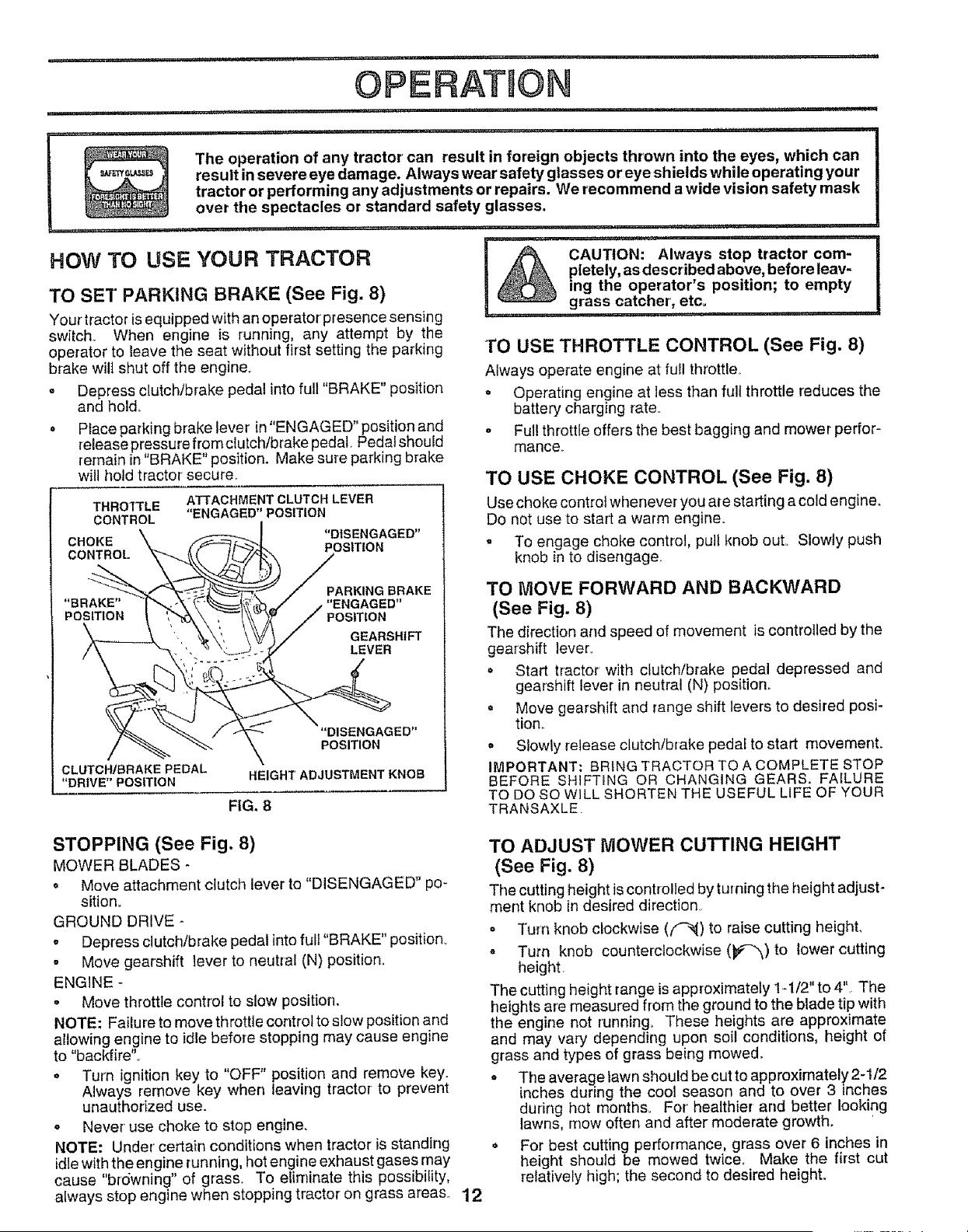
TO SET PARKING BRAKE (See Fig. 8)
Your tractor is equipped with an operator presence sensing
switch_ When engine is running, any attempt by the
operator to leave the seat without first setting the parking
brake wilt shut off the engine_
o Depress clutch/brake pedal into full "BRAKE" position
and hold.
• Place parking brake lever in "ENGAGED" position and
release pressure from dutch/brake pedal. Pedal should
remain in"BRAKE" position. Make sure parking brake
will hold tractor secure.
THROTTLE
CONTROL
CHOKE
CONTROL
' i,,11,11 iii, i i,, ==,, i ,,,,,1=,,,= ' , i ,=ll_
!
The operation of any tractor can result in foreign objects thrown into the eyes, which can
result in severe eye damage. Always wear safety glasses or eye shields while operating your
tractor or performing any adjustments or repairs. We recommend a wide vision safety mask
over the spectacles or standard safety glasses.
, ii ,i ,,i,lli,,,,,,,i,,
CAUTION: Always stop tractor com-
pletely, as described above, before leav-
ing the operator's position; to empty
grass catcher', etc.
....... ' ,,,,i .......
"BRAKE"
POSITION
ATTACHMENT CLUTCH LEVER
"ENGAGED" POSITION
"DISENGAGED"
POSITION
PARKING BRAKE
"ENGAGED"
POSITION
GEARSHIFT
LEVER
"DISENGAGED"
POSITION
CLUTCH/BRAKE PEDAL
"DRIVE" POSITION
HEIGHT ADJUSTMENT KNOB
FIG. 8
1"O USE THROTTLE CONTROL (See Fig. 8)
Always operate engine at full throttler
o Operating engine at less than full throttle reduces the
battery charging rate..
o Ful! throttle offers the best bagging and mower perfor-
mance..
TO USE CHOKE CONTROL (See Fig. 8)
Use choke control whenever you are starting a cold engine.
Do not use to start a warm engine.
. To engage choke control, pult knob out° Slowly push
knob in to disengage..
TO iVlOVE FORWARD AND BACKWARD
(See Fig. 8)
The direction and speed of movement is controlled by the
gearshift lever..
= Start tractor with clutch/brake pedal depressed and
gearshift lever in neutral (N) position..
o Move gearshift and range shift levers to desired posi-
tion..
o Slowly release clutch/brake pedai to start movement.
IMPORTANT: BRING TRACTOR TO A COMPLETE STOP
BEFORE SHiFTiNG OR CHANGING GEARS. FAILURE
TO DO SO WILL SHORTEN THE USEFUL LIFE OF YOUR
TRANSAXLE
STOPPING (See Fig. 8)
MOWER BLADES -
= Move attachment clutch lever to "DISENGAGED" po-
sition.
GROUND DRIVE -
o Depress clutch/brake pedal into full "BRAKE" position_
= Move gearshift lever to neutral (N) position.
ENGINE -
= Move throttle control to slow position,
NOTE: Failure to move throttle control to slow position and
allowing engine to idle before stopping may cause engine
to "backfire"°
Turn ignition key to "OFF" position and remove key.
Always remove key when leaving tractor to prevent
unauthorized use.
o Never* use choke to stop engine.
NOTE: Under' certain conditions when tractor is standing
idle with the engine running, hot engine exhaust gases may
cause "brdwning" of grass. To eliminate this possibility,
always stop engine when stopping tractor on grass areas 12
TO ADJUST MOWER CUTTING HEIGHT
(See Fig. 8)
The cutting height is controlled by turning the height adjust-
merit knob in desired direction_.
o Turn knob clockwise (f-_) to raise cutting heighL
° Turn knob counterclockwise (_P'-"_)to tower cutting
height
The cutting height range is approximately 1-1/2" to 4". The
heights are measured from the ground to the blade tip with
the engine not running° These heights are approximate
and may vary depending upon soil conditions, height of
grass and types of grass being mowed°
• The averagelawn should be cut to approximately 2-1/2
inches during the cool season and to over 3 inches
during hot months° For' healthier and better looking
lawns, mow often and after moderate growth.
o For best cutting performance, grass over 6 inches in
height should be mowed twice° Make the first cut
relatively high; the second to desired height.
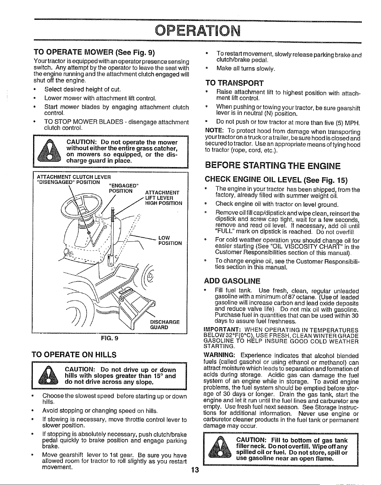
TO OPERATE MOWER (See Fig. 9)
Your tractor is equipped with an operator presence sensing
switch. Any attempt by the operator to leave the seat with
the engine running and the attachment clutch engaged will
shut off the engine.
. Select desired height of cut.
- Lower mower with attachment lift control°
• Start mower blades by engaging attachment clutch
control
. TO STOP MOWER BLADES _ disengage attachment
clutch control.
.... i1,, ,i, ,=.1,11,,,i.,11,,, ,i ii, i
CAUTION: Do not operate the mower
without either the entire grass catcher,
on mowers so equipped, or the dis-
charge guard in place.
• To restart movement, slowly release parking brake and
clutch/brake pedal,
• Make all turns sIowly.
TO TRANSPORT
. Raise attachment lift to highest position with attach-
ment lift control,
o When pushing or towing your tractor be sure gearshift
ever s n neutral (N) position,
o Do not push or tow tractor at more than five (5) MPH
NOTE: To protect hood from damage when transporting
yourtractoron a truck or a trailer, be sure hood isclosed and
secured to tractor_ Use an appropriate means of tying hood
to tractor (rope, cord, etc.)o
BEFORE STARTING THE ENGINE
ATTACHMENT CLUTCH LEVER
"DISENGAGED" POSITION "ENGAGED"
POSITtON
ATTACHMENT
LEVER
NIGH POSITION
FIG. 9
D|SCHARGE
GUARD
TO OPERATE ON HILLS
........ ,,i i,,,, i , i,
c'°T'o°°°n°' °r'°wn',
hills with slopes greater than 15 ° and !
do not drive across any slope.
................ i1_,,=,,= i
. Choose the slowest speed before starting up or down
hills_
= Avoid stopping or changing speed on hills.
o If slowing is necessary, move throttle control lever to
slower position°
= If stopping is absolutely necessary, push clutch/brake
pedal quickly to brake position and engage parking
brake.
= Move gearshift lever to 1st gear, Be sure you have
alIowed room for tractor to roll stightly as you restart
movement.
'13
CHECK ENGINE OIL LEVEL (See Fig. 15)
° The engine inyour tractor has been shipped, fromthe
factory, already filled with summer weight oil,
. Check engine oil with tractor on level ground,,
° Remove oil fill cap/dipstick and wipe clean, reinsert the
dipstick and screw cap tight, wait for a few seconds,
remove and read oil level° If necessary, add oil until
"FULL" mark on dipstick is reached, Do not overfilI
• For cold weather operation you should change oil for
easier starting (See "OIL VISCOSITY CHART" in the
Customer Responsibilities section of this manual) l
o To change engine oil, see the Customer Responsibili-
ties section in this manual.
ADD GASOLINE
° Fill fuel tank° Use fresh, clean, regular unleaded
gasoline with a minimum of 87 octane_ (Use of leaded
gasoline will increase carbon and lead oxide deposits
and reduce valve life) Do not mix oil with gasoline.
Purchase fuel in quantities that can be used within 30
days to assure fuel freshness.
IMPORTANT; WHEN OPERATING IN TEMPERATURES
BELOW 32°F(0"C), USE FRESH, CLEAN WINTER GRADE
GASOLINE TO HELP INSURE GOOD COLD WEATHER
STARTING.
WARNING: Experience indicates that alcohol blended
fuels (caUed gasohol or using ethanol or methanol) can
attract moisture which leads to separation and formation of
acids during storage° Acidic gas can damage the fuel
system of an engine while in storage. To avoid engine
problems, the fuel system should be emptied before stor-
age of 30 days or longer. Drain the gas tank, start the
engine and let it run until the fuel lines and carburetor are
empty. Use fresh fuel next season, See Storage Instruc-
tions for additional information. Never use engine or
carburetor cleaner products in the fuel tank or permanent
damage may occur,
I A CAUTION: Fill to bo.om of gas tank
J
_ filler neck. Do not overfill. Wipe off any |
spilled oil or fuel. Do not store, spill or J
use gasoline near an open flame,I ................
..........ii........... iii ,L,LII
OPERATION
................ iii i i.................... _,1!,.... t
TO START ENGINE (See Fig. 8)
When starting the engine for the first time or if the engine
has run out of fuel, it will take extra cranking time to move
fuel from the tank to the engine.
. Sit on seat in operating position, depress clutch/brake
pedal and set parking brake°
o Place gear shift lever in neutral (N) position°
• Move attachment clutch to "DISENGAGED" position
o Move throttfe contrel to fast position
. Pull choke control out for a cold engine start attempt.
For a warm engine start attempt the choke control may
not be needed.
Note: Before starting, read the warm and cold starting
procedures below.,
o insert key into ignition and turn key clockwise to"START"
position and release key as soon as engine starts, Do
net run starter continuously for more than fifteen sec-
onds per minute° If the engine does not start after
several attempts, push choke control in, wait a few
minutes and try again. If engine still does not start, pull
the choke control out and retry_
WARM WEATHER STARTING (50° F and above)
° When engine starts, slowly push choke control in until
the engine begins to run smoothly. If the engine starts
to run roughly, pull the choke controt out slightly for a
few seconds and then continue to push the control in
slowly,
• The attachments and ground drive can nowbe used If
the engine does not accept the load, restart the engine
and allow it to warm up for one minute using the choke
as described above°
COLD WEATHER STARTING (50 ° F and below)
• When engine starts, slowly push choke control in until
the engine begins to run srnoothty. Continue to push
the choke control in small steps allowing the engine to
accept small changes in speed and load, until the
choke control is fully in. If the engine starts to run
roughly, pull the choke control out slightly for a few
seconds and then continue to push the control in
stowly_ This may require an engine warm-up period
from several seconds to severat minutes, depending
on the temperature,
° The attachments can be used during the engine warm-
up period and may require the choke control be pulled
out slightly°
NOTE: If at a high altitude (above 3000 feet) or in cold
temperatures (below 32 F) the carburetor fuel mixture may
need to be adjusted for best engine per_ermance. See "TO
ADJUST CARBURETOR" in the Service and Adjustments
section of this manual.
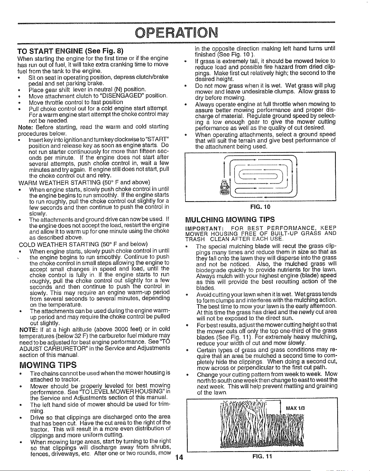
in the opposite direction making left hand turns until
finished (See Fig.. 10 ).
- If grass is extremely tall, it should be mowed twice to
reduce load and possible fire hazard from dried clip=
pings. Make fh'st cut relatively high; the second to the
desired height.
= Do not mow grass when it is weL Wet grass will plug
mewer and leave undesirable clumps. Allow grass to
dry before mowing.
• Always operate engine at full throttle when mowing to
assure better' mowing performance and proper dis-
charge of material., Regulate ground speed by select-
ing a tow enough gear to give the mower cutting
performance as well as the quality of cut desired.
o When operating attachments, select a ground speed
that will suit the terrain and give best performance of
the attachment being used.
MOWING TIPS
= Tire chains cannot be used when the mower housing is
attached to tractor.
• Mower should be properly leveled for best mowing
t_ it i
performance. See TOLEVELMOWERHOUSING n
the Service and Adjustments section of this manual.
• The left hand side of mower should be used for trim-
ming
. Drive so that clippings are discharged onto the area
that has been cut. Have the cut area to the right of the
tractor. This will result in a more even distribution of
clippings and more uniform cutting,.
• When mewing large areas, start by turning to the right
so that clippings will discharge away from shrubs,
fences, driveways, etc After' one or two rounds, mow
m ,J
FIG. 10
MULCHING MOWING TIPS
IMPORTANT: FOR BEST PERFORMANCE, KEEP
MOWER HOUSING FREE OF BUILT-UP GRASS AND
TRASH CLEAN AFTER EACH USE..
- The special mulching blade will recut the grass clip-
pings many times and reduce them in size so that as
they fal! onto the lawn they will disperse into the grass
and not be noticed° Also, the mulched grass will
biodegrade quickly to provide nutrients for the lawn.
Always mulch with your highest engine (blade) speed
as this witl provide the best recutting action of the
blades°
* Avoid cutting your lawn when it is wet° Wet grass tends
to form clumps and interferes with the mulching action.
The best time to mow your lawn is the early afternoon_
At this time the grass has dried and the newly cut area
will not be exposed to the direct sun.
. For best results, adjust the mower cutting height so that
the mower cuts off only the top one-third of the grass
blades (See Fig, 11 ). For extremely heavy mulching,
reduce your width of cut and mow slowly.
o Certain types of grass and grass conditions may re-
quire that an area be mulched a second time to com-
pletely hide the clippings. When doing a second cut,
mow across or perpendicular to the first cut path.
° Change your cutting pattern from week to week° Mow
north to south one week then change to east to west the
next week_ This will help prevent matting and graining
of the Iawnr
MAX 1/3
14 FIG. 11
CUSTOMER RESPONSmBIL TmES
....lUll'" ' I .... II'"UI'U'"' U'"
MAINTENANCE SCHEDULE .____._ _.._n_ _._ '
FILL IN DATES J_.j'__'_O_ _
ASYOUCOMPLETE
REGULARSERVtOE _b_ _.&/_ _.-q'/__.4_ _ _._ _£._ SERV
........................................................... J__.U,_ ERVICE DATES
Check BrakeOperation , _
CheckTire Pressure 6_
T Check for Loose Fasteners _ 6/7
a Sharpen/Replace MowerBlades
C LubricationChart
T CheckBattery Level/Recharge
0 ,, Clean BatteryandTerminals
a CheckTransaxle Cooling
Adjust Blade Belt(s) Tension
Adjust Motion Drive Belt(s) Tension
Check EngineOil Level 6/
Change EngineOi!
Clean Air Filter
N Clean Air Screen ......
G Inspect MuffiedSparkArrester
I Replace Oil Filter(If equipped)
ReptaceSparkPlug
ReplaceAir FilterPaper Cartridge
Replace FueIFilter
v'
,,_"
v' e,'
e/
_ ....................
-_1.2
J e"
1 - Change more often when operating under a heavy load or tn high ambient temperatures
2 - Service more oiten when operating in dirty or dusty conditions
3, If equipped with oil filter, change ell every 50 hours
4 - Replace blades more o!ten when mowing tn sandy soil
.5 - If equipped with adjuslabfe system
6 _Not required f! equipped with maintenance-free battery
7 - Tighten front axle pivot bolt to 3`5 h 4bs maximum
Do not overlighten
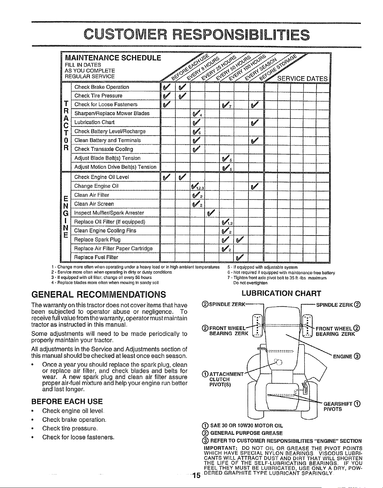
GENERAL RECOMMENDATIONS
The warranty on this tractor does not cover items that have
been subjected to operator abuse or negligence. To
receive full value from the warranty, operator must maintain
tractor as instructed in this manual.
Some adjustments will need to be made periodically to
properly maintain your tractor.
All adjustments in the Service and Adjustments section of
this manual should be checked at least once each season°
* Once a year you should replace the spark plug, clean
or replace air filter, and check blades and belts for
wear. A new spark plug and clean air filter assure
proper air-fuel mixture and help your engine run better
and last longer.
LUBRICATION CHART
ENGINE (_)
(_ CLUTCH
PIVOT(S)
BEFORE EACH USE
- Check engine oil level,
o Check brake operation.
- Check tire pressure.
= Check for loose fastener&
PIVOTS
(_ SAE 30 OR 10W30 MOTOR OIL
(_) GENERAL PURPOSE GREASE
(_) REFER TO CUSTOMER RESPONSIBILITIES "ENGINE" SECTION
IMPORTANT; DO NOT OIL OR GREASE THE PIVOT POINTS
WHICH HAVE SPEC}AL NYLON BEARINGS, VISCOUS LUBRI-
CANTS WILL ATTRACT DUST AND DiRT THAT WiLL SHORTEN
THE LIFE OF THE SELF-LUBRICATING BEARINGS, IF YOU
FEEL THEY MUST BE LUBRICATED, USE ONLY A DRY, POW-
1 5 DERED GBAPHiTE TYPE LUBRICANT SPARINGLY
i ....
RESPONSmBILITIES
1,1,1111,,111 ,,, i ,i ,i, I ,,,111 i i ii ..... i i,,,,i .............
TRACTOR
Always observe safety rules when pedorming any mainte-
nance.
BRAKE OPERATION
If tractor requires more than six (6) feet stopping distance
at high speed inhighest gear, then brake must be adjusted.
(See "TO ADJUST BRAKE" in the Service and Adjust-
ments section of this manual).
TIRES
- Maintain proper' air pressure in all tires (See "PROD-
UCT SPECIFICATIONS" on page 3 of this manual)
Keep tires free of gasoline, oil, or' insect control cherni-
cats which can harm rubber.
. Avoid stumps, stones, deep ruts, sharp objects and
other hazards that may cause tire damage.
NOTE: To seal tire punctures and prevent fiat tires due to
slow leaks, tire sealant may be purchased from your local
parts dealer, Tire sealant also prevents tire dry rot and
corrosion.
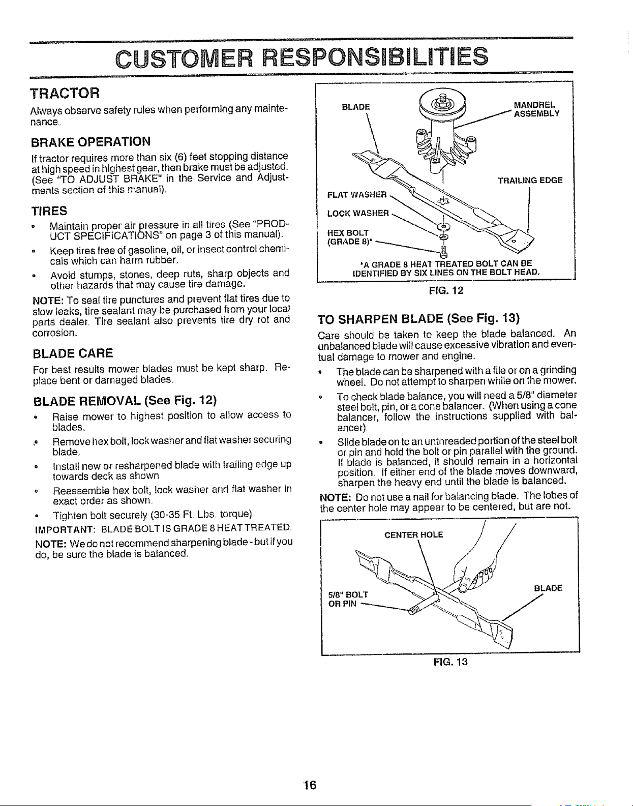
BLADE CARE
For best results mower blades must be kept sharp, Re-
place bent or' damaged blades.
BLADE REMOVAL (See Fig, 12)
o Raise mower to highest position to allow access to
blades.
., Remove hex bolt, lock washerand flat washer securing
blade
o Install new or resharpened blade with trailing edge up
towards deck as shown
,, Reassemble hex bolt, lock washer and flat washer in
exact order as shown
= Tighten bolt securely (30-35 Ft. Lbs. torque)
IMPORTANT: BLADE BOLT IS GRADE 8 HEAT TREATED.
NOTE: We do not recommend sharpening blade- but if you
do, be sure the blade is balanced.
BLADE MANDREL
ASSEMBLY
TRAILING EDGE
LOCK WASHER
HEXBOLT
(GRADE 8)*
"A GRADE 8 HEAT TREATED BOLT CAN BE
IDENTIFIED BY SIX LINES ON THE BOLT HEAD.
FIG. 12
TO SHARPEN BLADE (See Fig. 13)
Care should be taken to keep the blade balanced. An
unbalanced blade will cause excessive vibration and even-
tual damage to mower and engine.
. The blade can be sharpened with a file or on a grinding
wheel Do not attempt to sharpen while on the mower.
° To check blade balance, you will need a 5/8" diameter
steel bolt, pin, or a cone balancer. (When using a cone
balancer, follow the instructions supplied with bat-
ancer),
o Slide blade on to an unthreaded portion of the steel bolt
or pin and hold the bolt or pin parallet with the ground.
If blade is balanced, it should remain in a horizontal
position, tf either' end of the blade moves downward,
sharpen the heavy end until the blade is balanced.
NOTE: Do not use a nail for balancing blade. The lobes of
the center hole may appear to be centered, but are not.
CENTER HOLE
FIG. 13
16
I'HI'"I'I '1 " ' "1 '"1" '1' I
CUSTOMER RESPONSmBBLUTJ
,i i1,,
BATTERY
Your tractor has a batter,/charging system which is suffi-
cient for normal use_ However, periodic charging of the
battery with an automotive charger will extend its life..
• Keep battery and terminals clean°
= Keep battery bolts tight.
. Keep smalt vent holes openr
• Recharge at 6-10 amperes for 1 hour.
TO CLEAN BATTERY AND TERMINALS
Corrosion and dirt on the battery and terminals can cause
the battery to 'leak" power_
o Remove terminal guard,
o Disconnect BLACK battery cable first then RED bat*
tery cable and remove battery from tractor.
= Rinse the battery with plain water and dry.
, Clean terminals and batterycable ends with wire brush
until bright.
o Coat terminals with grease or petroleum jelly.
o Reinstall battery (See "CONNECT BATTERY" in the
Assembly section of this manual),
V-BELTS
Check V-belts for deterioration and wear after 100 hours of
operation and replace if necessary,, The belts are not
adjustable. RepIace belts if they begin to slip from wear_
TRANSAXLE COOLING
Keep transaxte free from build_up of dirt and chaff which
can restrict cooling
IHI , i , I,,,I,,,HI .
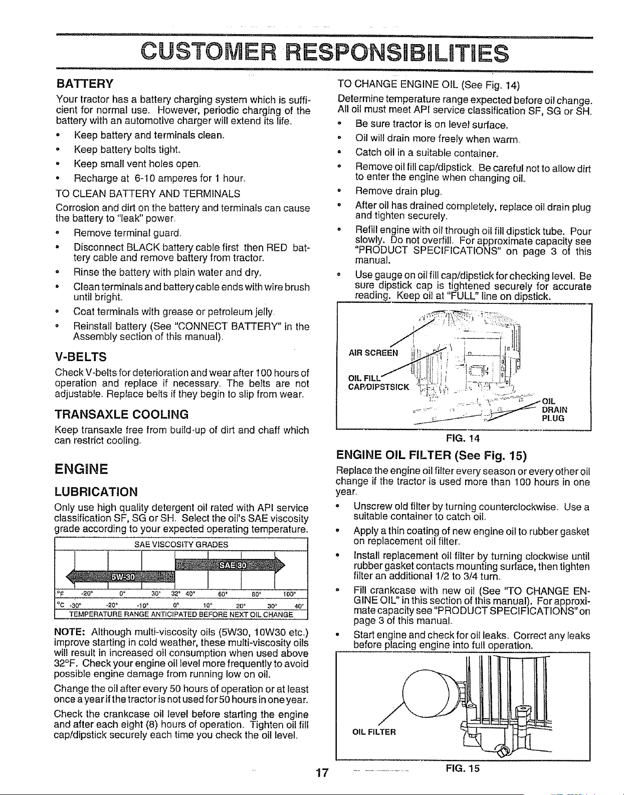
TO CHANGE ENGINE OIL (See Fig° 14)
Determine temperature range expected before oil change.
All oil must meet API service classification SF, SG or SH,,
o Be sure tractor is on level surface,,
o Oil will drain more freely when warm,
= Catch oil in a suitable container.
', Remove oil fill cap/dipstick, Be careful not to allow dirt
to enter the engine when changing oil,,
o Remove drain plug,,
= After oil has drained completely, replace oil drain plug
and tighten securely.
- Refill engine with oil through oil filt dipstick tube. Pour
slowly, Do not overfill For approximate capacity see
"PRODUCT SPECIFICATIONS" on page 3 of this
manual,
. Use gauge on oil fill cap/dipstick forchecking level. Be
sure dipstick cap is tightened securely for accurate
reading. Keep oil at "FULL" line on dipstick.
AIR SCREEN ' !i_' n _ t r
_/i!! t _--_ ,i' _
..... '= ', , : _DRAIN
;/ PLUG
ENGINE
LUBRICATION
Only use high quality detergent oil rated with API service
classification SF, SG or SH. Setect the oil's SAE viscosity
grade according to your expected operating temperature°
SAE VISCOSITY GRADES
!
r
,IC,-3,0 = "20" "10" 0_ 10 _ 20 _ 30 _ 40_i
TEMPERATURE RANGE ANTiCiPATED BEFORE NEXT OIL CHANGE
NOTE: Although multi-viscosity oils (5W30, 10W30 etc_)
improve starting in cold weather, these multi-viscosity oils
will result in increased oil consumption when used above
32°F. Check your engine oil level more frequently to avoid
possible engine damage from running tow on oil.
Change the oil after every 50 hours of operation or at least
once a year if t he tractor is not used for 50 hours in one year°
Check the crankcase oil level before starting the engine
and after each eight (8) hours of operation. Tighten oil fill
cap/dipstick securely each time you check the oil level,.
FIG. !4
ENGINE OIL FILTER (See Fig. 15)
Replace the engine oil filter every season or every other oil
change if the tractor is used more than 100 hours in one
year°
= Unscrew old filter by turning counterclockwise. Use a
suitable container to catch oil.
o Apply a thin coating of new engine oil to rubber gasket
on replacement oil filter_
• Install replacement oil filter by turning clockwise until
rubber gasket contacts mounting surface, then tighten
filter an additional 1/2 to 3/4 turn_
= Fill crankcase with new oil (See "TO CHANGE EN-
GINE OIL" in this section of this manual). For approxi-
mate capacity see "PRODUCT SPECIFICATIONS" on
page 3 of this manual
= Start engine and check for oit leaks,, Correct any Ieaks
before placing engine into full operation.
OIL FILTER
17 ...................... FIG. 15
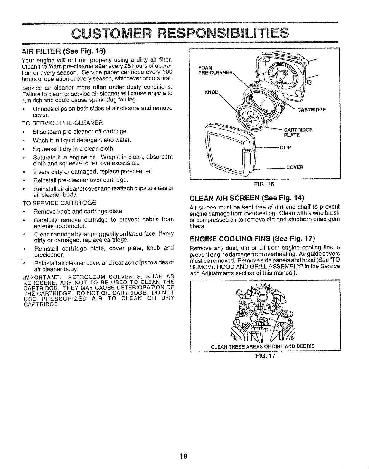
AIR FILTER (See Fig. 16)
Your engine will not run properly using a dirty air filter',.
Ctean the foam pre-cleaner after' every 25 hours of opera-
tion or every season. Service paper' cartridge every 100
hours of operation or every season, whichever occurs first.
Service air cleaner' more often under dusty conditions_
Failure to clean or service air cleaner will cause engine to
run rich and could cause spark plug fouling°
. Unhook clips on both sides of air cleanre and remove
COVer.
TO SERVICE PRE-CLEANER
= Slide foam pre-cleaner off cartridge.
• Wash it in liquid detergent and water.
• Squeeze it dry in a clean cloth.
o Saturate it in engine oil Wrap it in clean, absorbent
cloth and squeeze to remove excess oil.
= If very dirty or damaged, replace pre-cieaner.
• Reinstall pre-cleaner over cartridge_
° Reinstall air' cleanercover and reattach clips to sides of
air cleaner body.
TO SERVICE CARTRIDGE
o Remove knob and cartridge plate.
• Carefully remove cartridge to prevent debris from
entering carburetor.
o Clean cartridge by tapping gently on flat surface Ifvery
dirty or damaged, replace cartridge,
= Reinstall cartridge plate, cover plate, knob and
precleaner.
. Reinstall air cleaner cover and reattach clips to sides of
air cleaner body.
IMPORTANT, PETROLEUM SOLVENTS, SUCH AS
KEROSENE, ARE NOT TO BE USED TO CLEAN THE
CARTRIDGE. THEY MAY CAUSE DETERIORATION OF
THE CARTRIDGE DO NOT OIL CARTRIDGE,, DO NOT
USE PRESSURIZED AIR TO CLEAN OR DRY
CARTRIDGE
FOAM
I
KNOB
J
CARTRIDGE
PLATE
CLIP
FIG. 16
CLEAN AIR SCREEN (See Fig. 14)
Air screen must be kept free of dirt and chaff to prevent
engine damage from overheating. Clean with a wire brush
or compressed air' to remove dirt and stubborn dried gum
fibers_
ENGINE COOLING FINS (See Fig, 17)
Remove any dust, dirt or oil from engine cooling fins to
prevent eng inedamage from overheating., Air guide covers
must be removed.. Remove side panels and hood (See "TO
REMOVE HOOD AND GRILL ASSEMBLY" in the Service
and Adjustments section of this manual).
CLEAN THESE AREAS OF DIRT AND DEBRIS
FIG. 17
18
i1,1,,,111,11i,i
CUSTOMER
i,,,11,,,11,i 'I'II'IIMII I'
MUFFLER
Inspect and replace corroded muffler and spark arrester (if
equipped) as it could create a fire hazard and/or damage.
SPARK PLUGS
Replace spark plugs at the beginning of each mowing
season or after every t00 hours of operation, whichever
occurs first. Spark plug type and gap setting are shown in
"PRODUCT SPECIFICATIONS" on page 3 of this manual.
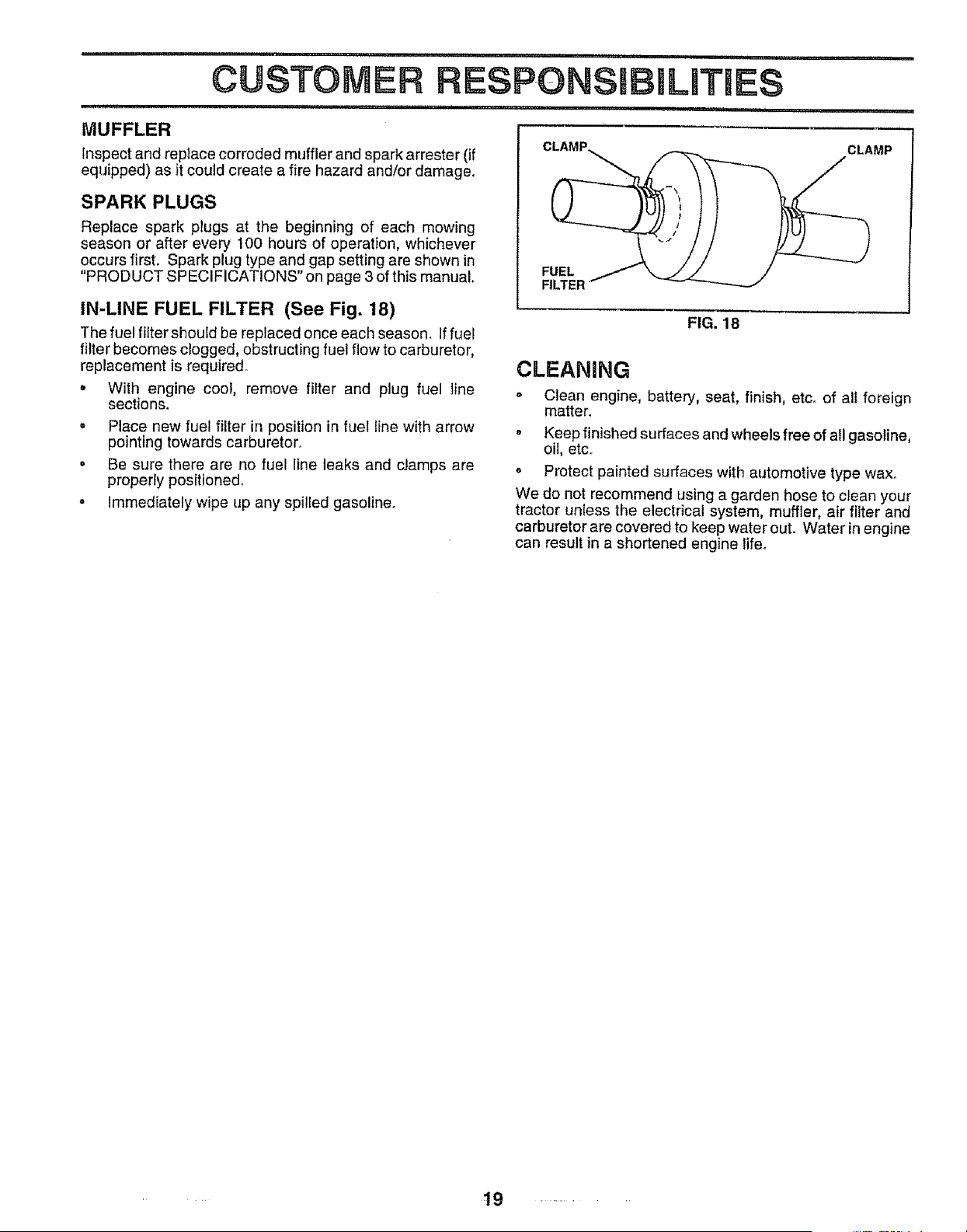
IN-LINE FUEL FILTER (See Fig. 18)
The fuel filter should be replaced once each season. If fuel
filter becomes clogged, obstructing fuel flow to carburetor,
replacement is required
o With engine coo!, remove filter and plug fuel line
sections.
= Place new fuel filter in position in fuel line with arrow
pointing towards carburetor°
o Be sure there are no fuel line leaks and damps are
properly positioned°
• Immediately wipe up any spilled gasoline.
FUEL
FILTER
CLEANING
CLAMP
FIG. 18
= Clean engine, battery, seat, finish, etc. of all foreign
matter.
o Keep finished surfaces and wheels free of all gasoline,
oil, etc.
o Protect painted surfaces with automotive type wax°
We do not recommend using a garden hose to clean your
tractor unless the electrical system, muffler, air _ter and
carburetor are covered to keep water out. Water in engine
can result in a shortened engine lifeo
t9 ........
.......................... i
,,i,i,! ,i,,i,,,11,1,11,=,_L_
SERVICE AN ADJUSTMENTS
i, iiii .....................
,,,,, , , i,,,,,,i,,,,11, ,, i 1,1,,,,,i, ,1,1,11 ._,,_,_ . i, , ,,,i,,,,i,,
CAUTION: BEFORE PERFORMING ANY SERVICE OR ADJUSTMENTS:
, Depress clutch/brake pedal fully and set parking brake.
• Place gearshift lever in neutral (N) position.
= Place attachment clutch in "DISENGAGED" position.
= Turn ignition key "OFF" and remove key.
Make sure the blades and all moving parts have completely stopped.
Disconnect spark plug wire from spark plug and place wire where it cannot come in contact with
plug.
,,i,i i,, I ,,, i.i, i,iii.
TRACTOR
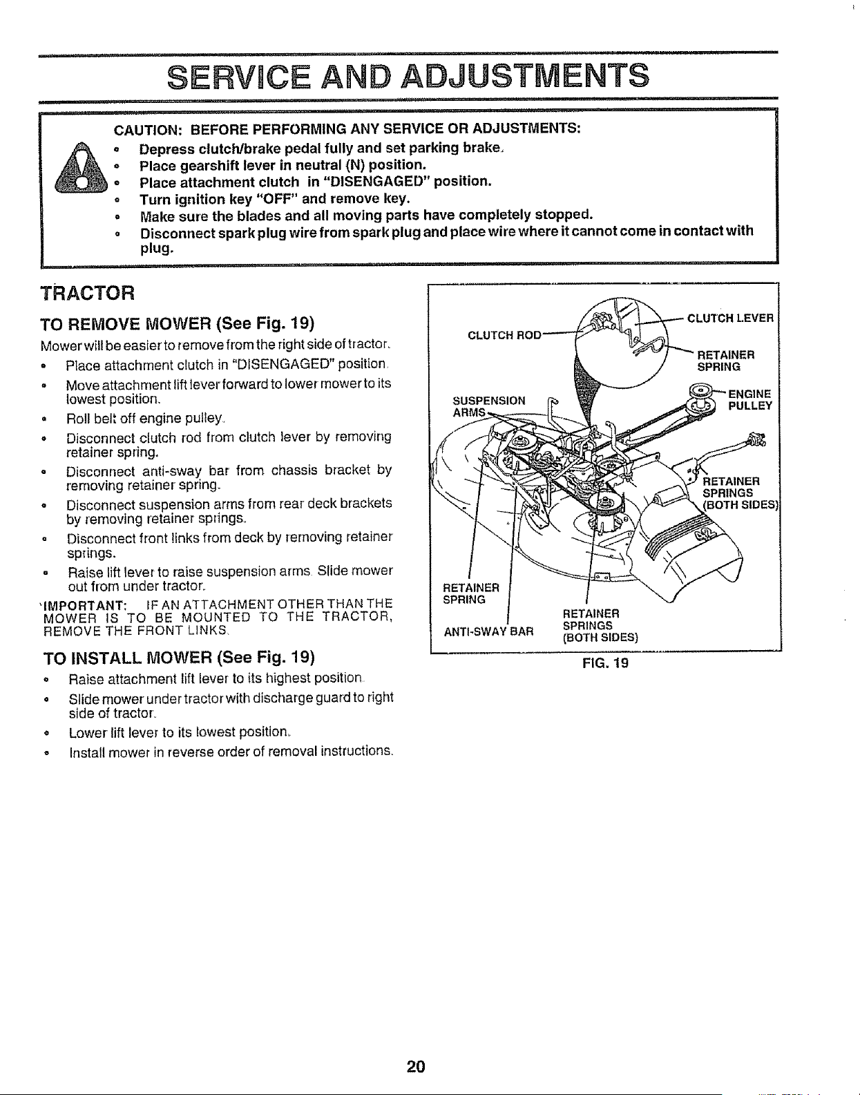
TO REMOVE MOWER (See Fig. 19)
Mower wil!be easier to remove from the rightside of tractor_
o Place attachment clutch in "DISENGAGED" position
, Move attachment lift lever forward to lower mower to its
lowest position.
o Roi! belt off engine pulley
• Disconnect clutch rod from clutch lever by removing
retainer spring.
o Disconnect anti*sway bar from chassis bracket by
removing retainer spring°
o Disconnect suspension arms from rear deck brackets
by removing retainer springs°
, Disconnect front links from deck by removing retainer
springs.
. Raise lift lever to raise suspension arms Slide mower
out from under tractor.
'IMPORTANT: IF AN ATTACHMENT OTHER THAN THE
MOWER IS TO BE MOUNTED TO THE TRACTOR.
REMOVE THE FRONT LINKS.
TO INSTALL MOWER (See Fig. 19)
° Raise attachment lift lever to its highest position
• Slide mower under tractor with discharge guard to right
side of tractor
o Lower lift lever to its lowest position_
o Install mower in reverse order of removal instructions.
CLUTCH
RETAINER
SPRING
ANTI-SWAY BAR
RETAINER
SPRINGS
(BOTH SIDES)
FIG. 19
RETAINER
SPRING
PULLEY
SPRINGS
BOTH SIDES
20
.......................... i, ,, •
SERVmCE
.................. nuunu , , ,,,, i ,, i
TO LEVEL MOWER HOUSING
Adjust the mower while tractor is parked on level ground or
driveway. Make sure tires are properly inflated (See
"PRODUCT SPECIFICATIONS" on page 3 of this manual).
if tires are over or underinflated, you will not properly adjust
your mower.
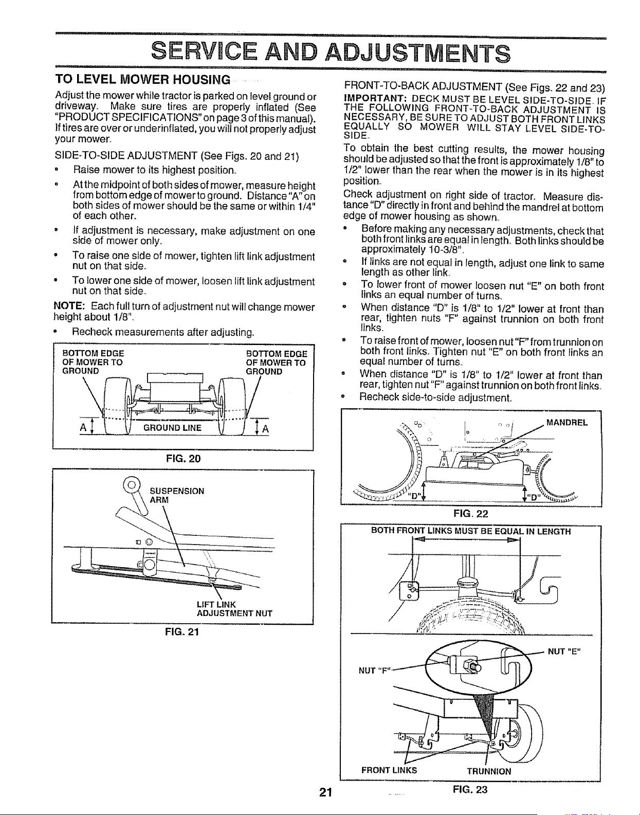
SIDE-TO-SiDE ADJUSTMENT (See Figs° 20 and 21)
° Raise mower to its highest position.
° At the midpoint of both sides of mower, measure height
from bottom edge of mower to ground. Distance"A" on
both sides of mower should be the same or within 1/4"
of each other.
° If adjustment is necessary, make adjustment on one
side of mower only.
o To raise one side of mower, tighten lift link adjustment
nut on that side.
• To lower one side of mower, loosen lift link adjustment
nut on that side°
NOTE: Each full turn of adjustment nut wil} change mower
height about 1/8".
• Recheck measurements after adjusting.
BOTTOM EDGE BOTTOM EDGE
OF MOWER TO OF MOWER TO
GROUND GROUND
GROUND LINE A
FIG. 20
SUSPENSION
ARM
LIFT LINK
ADJUSTMENT NUT
FIG_ 21
:---':; ..................... -- H'UlI"IIn' ' ,"1I '
AND ADJUSTMENTS
,, ,r_,,,llll..... i,,,llnn
FRONT-TO-BACK ADJUSTMENT (See Figs_ 22 and 23)
IMPORTANT: DECK MUST BE LEVEL SIDE-TO-SIDEo IF
THE FOLLOWING FRONT-TO-BACK ADJUSTMENT IS
NECESSARY, BE SURE TO ADJUST BOTH FRONT LINKS
EQUALLY SO MOWER WILL STAY LEVEL SIDE-TO-
SIDE.
To obtain the best cutting results, the mower housing
should be adjusted so that the front is approximately !/8" to
1/2" lower than the rear when the mower is in its highest
position°
Check adjustment on right side of tractor. Measure dis-
tance"D" directly in front and behind the mandrel at bottom
edge of mower housing as shown_
o Before making any necessary adjustments, check that
both front links are equal in length. Both links should be
approximately 10-3/8".
o If Iinks are not equal in length, adjust one link to same
length as other link.
,, To tower front of mower loosen nut "E" on both front
links an equal number of turns.
,, When distance "D" is t/8" to 1/2" lower at front than
rear, tighten nuts "F" against trunnion on both front
links.
° To raise front of mower, loosen nut"F'from trunnion on
both front links. Tighten nut "E" on both front links an
equal number of turns.
• When distance "D" is t/8" to 1/2" lower at front than
rear, tighten n ut"F" against trunnion on both front links.
,, Recheck side-to-side adjustment.
_ o_ _ _,_ MANDREL
FIG. 22
BOTH FRONT LINKS MUST BE EQUAL IN LENGTH
NUT "E"
21
FRONT LINKS TRUNNION
FIG. 23
,,,=,,,= I,,H....... i _ ....................ii i =, ,,,1=,
SEIRVmCEAND ADJUSTMENTS
.... ,',, t ,,,11,,,,1 iN ,i ...... ii .....u ...... , ....... Hm 1,, NI
WITH PARKING BRAKE "ENGAGED"
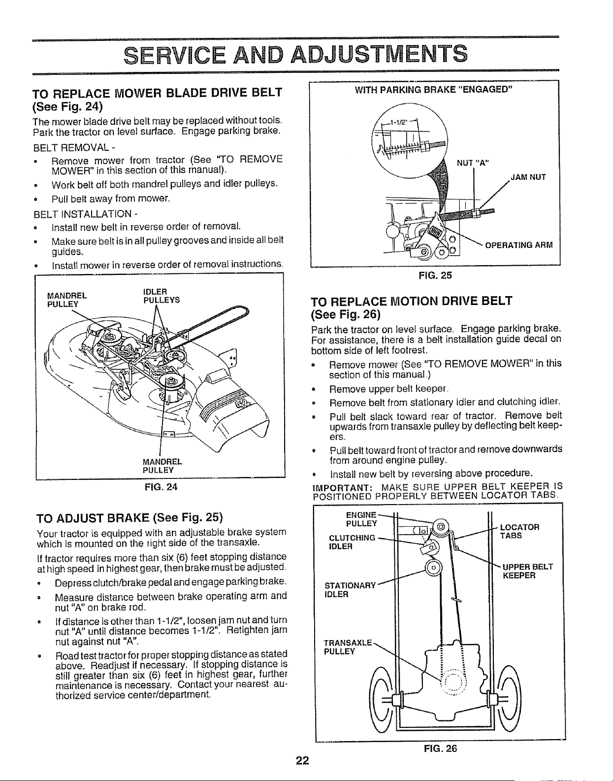
TO REPLACE MOWER BLADE DRIVE BELT
(See Fig. 24)
The mower blade drive belt may be replaced without tools.
Park the tractor on level surface° Engage parking brake.
BELT REMOVAL -
. Remove mower from tractor (See "TO REMOVE
MOWER" in this section of this manual),,
o Work belt off both mandrel pulleys and idler pulleys.
. Pull belt away from mower,
BELT INSTALLATION -
• Install new belt in reverse order of removal
o Make sure belt is in all pulley grooves and inside all belt
guides°
° Install mower in reverse order of removal instructions,
MANDREL IDLER
PULLEY PULLEYS
MANDREL
PULLEY
FIG, 24
TO ADJUST BRAKE (See Fig. 25)
Your tractor is equipped with an adjustable brake system
which is mounted on the right side of the transaxle.
If tractor' requires more than six (6) feet stopping distance
at high speed in highest gear, then brake must be adjusted.
o Depress clutch/brake pedal and engage parking brake_
, Measure distance between brake operating arm and
nut "A" on brake rod.
- If distance is other than 1-1/2", loosen jam nut and turn
nut "A" until distance becomes 1-1/2'L Retighten jam
nut against nut "A"°
• Road test tractor for proper stopping distance as stated
above. Readjust if necessary, tf stopping distance is
stilJ greater than six (6) feet in highest gear, further
maintenance is necessary. Contact your nearest au-
thorized service center!department.
NUT "A"
J AM NUT
1NG ARM
FIG. 25
TO REPLACE MOTION DRIVE BELT
(See Fig. 26)
Park the tractor on level surface_ Engage parking brake.
For assistance, there is a belt installation guide decal on
bottom side of left footrest,,
• Remove mower (See "TO REMOVE MOWER" in this
section of this manual,)
o Remove upper' belt keeper
o Remove belt from stationary idler and clutching idler,,
• Pul_ bett slack toward rear' of tractor'. Remove belt
upwards from transaxle pulley by deflecting belt keep-
efso
. Pull belt toward front of tractor and remove downwards
from around engine pulley.
o Install new belt by reversing above procedure.
IMPORTANT: MAKE SURE UPPER BELT KEEPER IS
POSITIONED PROPERLY BETWEEN LOCATOR TABS.
PULLEY
IDLER
TABS
IDLER
KEEPER
PULLEY
22
FIG. 26
n .... i=........ r"n , ,'l"ull " ,..rl_l i. i.in. i... ....
SERVICE AND ADJUSTMENTS
i1...i..... .. ,,..ul.i..... i..UUlU i ., _r....,... i .............. i.....
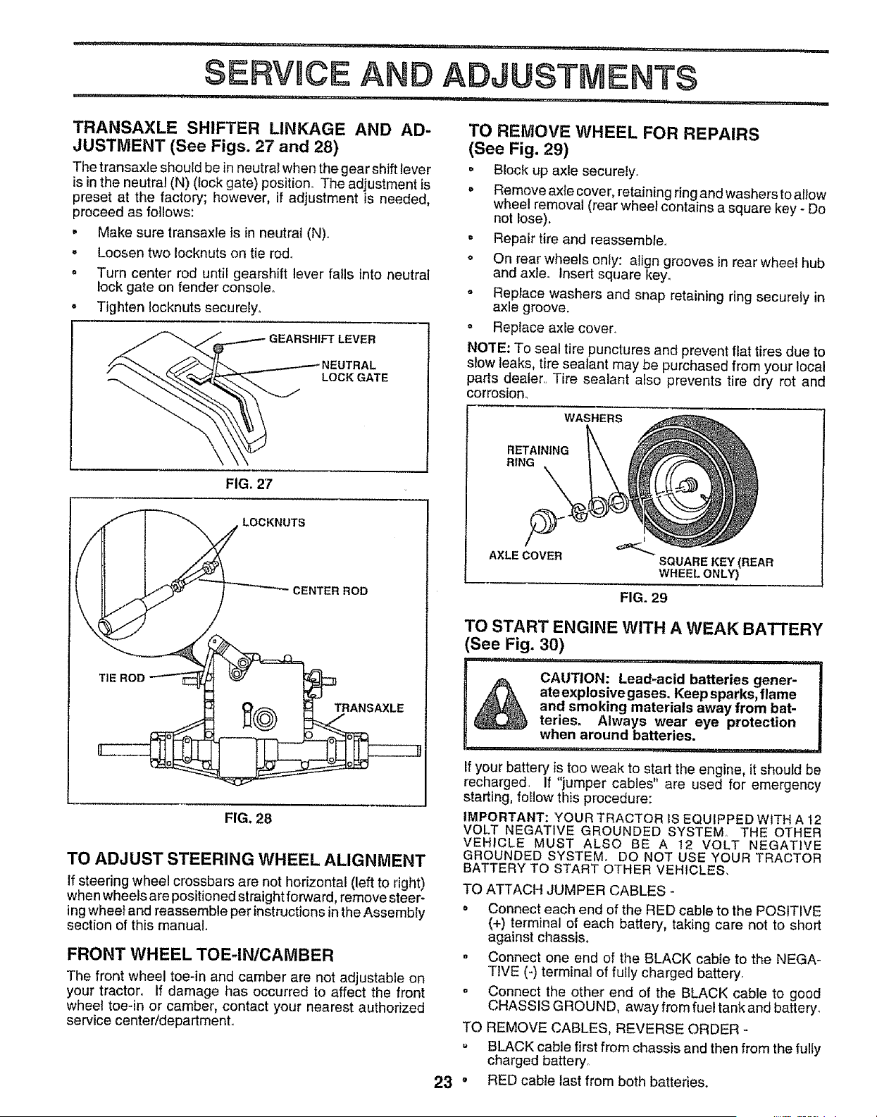
TRANSAXLE SHIFTER LINKAGE AND AD-
JUSTMENT (See Figs. 27 and 28)
Tile transaxle should be in neutral when the gear shift lever
is in the neutral (N) (lock gate) position. The adjustment is
preset at the factory; however, if adjustment is needed,
proceed as follows:
• Make sure transaxle is in neutrat (N)o
- Loosen two Iocknuts on tie rod.
= Turn center rod until gearshift lever falls Into neutral
lock gate on fender console.
= Tighten !ocknuts securely.
LOCK GATE
FIG. 27
LOCKNUTS
CENTER ROD
TRANSAXLE
FIG. 28
TO ADJUST STEERING WHEEL ALIGNMENT
If steering wheel crossbars are not horizontal (left to right)
when wheels are positioned straight forward, remove steer-
ing wheel and reassemble per instructions in the Assembly
section of this manual.
FRONT WHEEL TOE-IN/CAMBER
The front wheel toe-in and camber are not adjustable on
your tractor. If damage has occurred to affect the front
wheel toe-in or camber, contact your nearest authorized
service center/departmento
TO REMOVE WHEEL FOR REPAIRS
(See Fig. 29)
o Block up axle securely.
o Remove ax{e cover, retaining ring and washersto allow
wheel removal (rear whee_ contains a square key - Do
not lose).
, Repair tire and reassemble°
° On rear wheels only: align grooves in rear wheel hub
and axle. Insert square key°
= Replace washers and snap retaining ring securely in
axle groove.
o Replace axle cover.
NO'fE: To seal tire punctures and prevent flat tires due to
slow leaks, tire sealant may be purchased from your local
parts dealer,, Tire sealant also prevents tire dry rot and
corrosion.
WASHERS
RETAINING
RING
AXLECOVER
t
SQUARE KEY(REAR
WHEELONLY)
FIG. 29
TO START ENGINE WITH A WEAK BATTERY
(See Fig. 30)
i,fr,rf ,,,i ,u, ......... m I,IPI,, ii ,ILLLL,H ,,11,111
i _ CAUTION: Lead-acid batteries gener-
,_ ateexplosive gases. Keep sparks, flame
_ and smoking materials away from bat-
I _ teries. Always wear eye protection
when around batteries
If your battery is too weak to start the engine, it should be
recharged. If "jumper cables" are used for emergency
starting, {etiow this procedure:
IMPORTANT: YOUR TRACTOR iS EQUIPPED WITH A 12
VOLT NEGATIVE GROUNDED SYSTEM,, THE OTHER
VEHICLE MUST ALSO BE A 12 VOLT NEGATIVE
GROUNDED SYSTEM. DO NOT USE YOUR TRACTOR
BATTERY TO START OTHER VEHICLES,
m
a
TO
23"
TO ATTACH JUMPER CABLES -
o Connect each end of the RED cable to the POSITIVE
(+) terminal of each battery, taking care not to short
against chassis.
Connect one end of the BLACK cable to the NEGA-
TIVE (-) terminal of fully charged battery,
Connect the other end of the BLACK cable to good
CHASSIS GROUND, away from fuel tank and battery.
REMOVE CABLES, REVERSE ORDER -
BLACK cable first from chassis and then from the fully
charged battery.
RED cable last from both batteries.
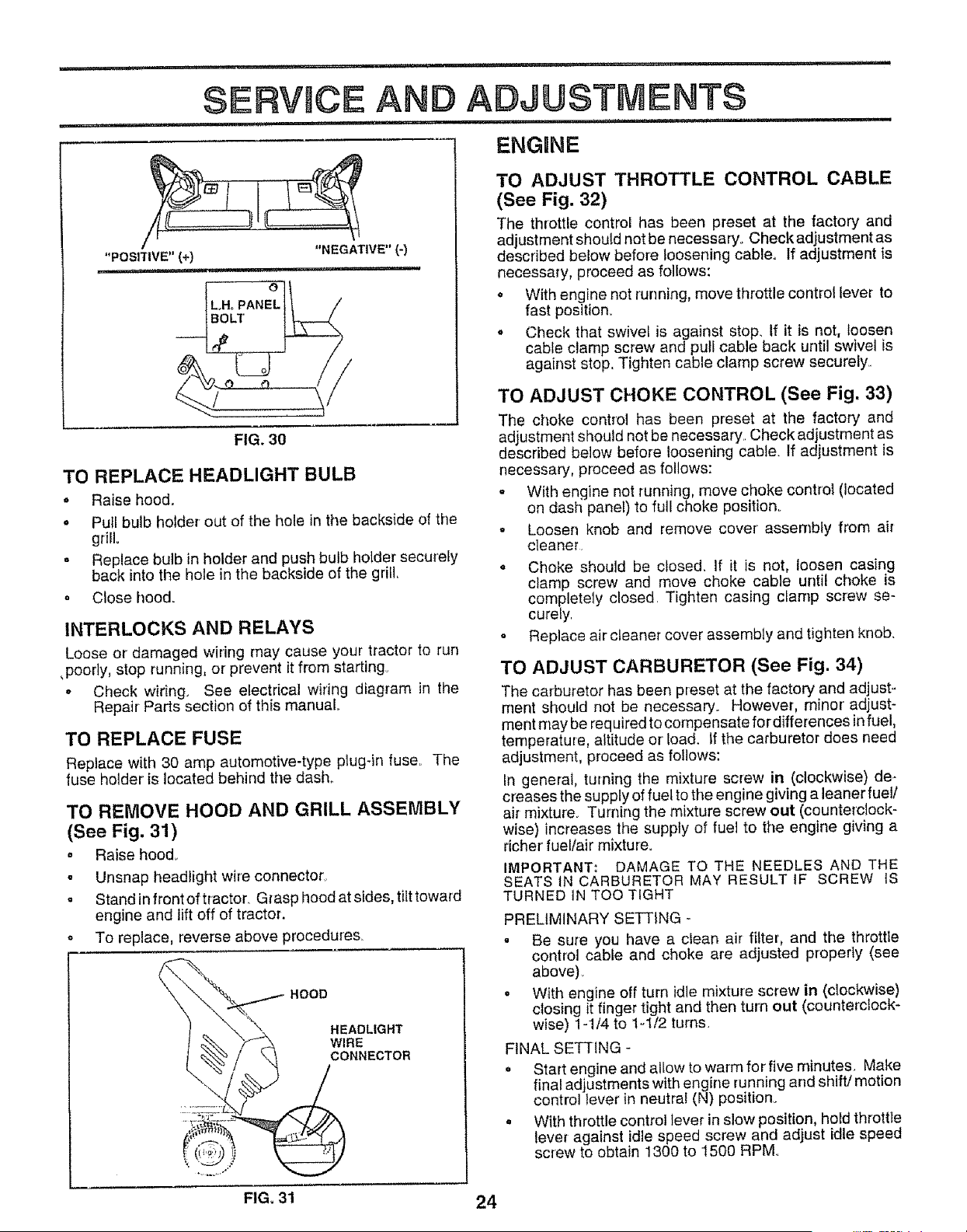
"POSITIVE" (+) "NEGATIVE" (-)
i, ,II,H, H'HI
FIG. 30
TO REPLACE HEADLIGHT BULB
• Raise hood°
• Pull bulb holder out of the hole in the backside of the
gdJL
° Replace bulb in holder and push bulb holder securety
back into the hole in the backside of the grill,
o Close hood.
INTERLOCKS AND RELAYS
Loose or damaged wiring may cause your tractor to run
,poody, stop running, or prevent it from starting°
• Check wiring. See electrical wiring diagram in the
Repair Parts section of this manual
TO REPLACE FUSE
Replace with 30 amp automotive-type plug-in fuse The
fuse holder is located behind tile dash
TO REMOVE HOOD AND GRILL ASSEMBLY
(See Fig. 31)
. Raise hood
° Unsnap headlight wire connector
• Stand in front of tractor Grasp hood at sides, tilt toward
engine and lift off of tractor.
o To replace, reverse above procedures
HOOD
HEADLIGHT
O_ECTOR
TO ADJUST THROTTLE CONTROL CABLE
(See Fig. 32)
The throttle control has been preset at the factory and
adjustment should not be necessary. Check adjustment as
described below before loosening cable. If adjustment is
necessary, proceed as follows:
,, With engine not running, move throttle controllever to
fast position.
o Check that swivel is against stop. If it is not, loosen
cable clamp screw and pull cable back until swivel is
against stop Tighten cable clamp screw securely
TO ADJUST CHOKE CONTROL (See Fig, 33)
The choke control has been preset at the factory and
adjustment should not be necessary Check adjustment as
described below before loosening cable. If adjustment is
necessary, proceed as follows:
= With engine not running, move choke control (located
on dash panel) to full choke position.
o Loosen knob and remove cover assembly from air
cleaner
o Choke should be closed, If it is not, loosen casing
clamp screw and move choke cable until choke is
completely closed Tighten casing cfarnp screw se-
curely
= Replace air cteane_ cover assembly and tighten knob,
TO ADJUST CARBURETOR (See Fig. 34)
The carburetor has been preset at the factory and adjust _
ment should not be necessary. However, minor adjust-
ment may be required to compensate for differences in fuel,
temperature, altitude or load. If the carburetor does need
adjustment, proceed as follows:
in general, turning the mixture screw in (clockwise) de-
creases the supply of fuel to the engine giving a leaner fuel/
air mixture Turning the mixture screw out (counterclock-
wise) increases the supply of fuel to the engine giving a
richer fuel/air mixture.
IMPORTANT. _ DAMAGE TO THE NEEDLES AND THE
SEATS tN CARBURETOR MAY RESULT IF SCREW IS
TURNED 1N TOO TIGHT
PRELIMINARY SETTING -
. Be sure you have a clean air filter, and the throttle
control cable and choke are adjusted properly (see
above)
o With engine off turn idle mixture screw in (clockwise)
closing it finger tight and then turn out (counterclock-
wise) 1-1/4 to 1-1/2 turns.
FINAL SETTING -
= Start engine and allow to warm for five minutes Make
final adjustments with engine running and shift/motion
control lever in neutral (N) position_
. With throttle control lever in slow position, hold throttte
lever against idle speed screw and adjust idle speed
screw to obtain 1300 to 1500 RPM
FIG. 31 24
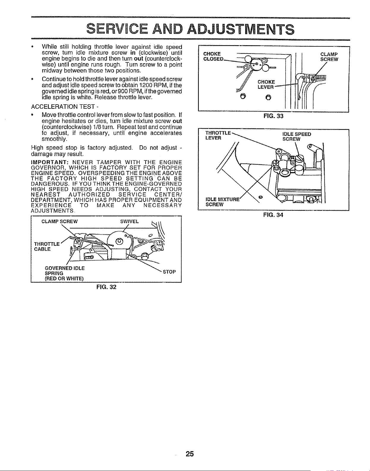
N
i iii " n ,, ,i.,,,,,11111,,i i ,i, i1,,,, i
SERVICE ANO ADJUSTMENTS
i1,1 i,
CHOKE
- While still holding throttle lever against idle speed
screw, turn idle mixture screw in (clockwise) until
engine begins to die and then turn out (counterclock-
wise) until engine runs rough. Turn screw to a point
midway between those two positions.
, Continue to hold throttle lever against idle speed screw
and adjust idle speed screw to obtain 1200 RPM, if the
governed idle spring is red, org00 RPM, if the governed
idle spring is white. Release throttle lever.
ACCELERATION TEST -
• Move throttle control lever from slow to fast position° If
engine hesitates or dies, turn idle mixture screw out
(counterclockwise) l/Sturno Repeat test and continue
to adjust, if necessary, until engine accelerates
smoothly.
High speed stop is factory adjusted.. Do not adjust -
damage may result,
IMPORTANT: NEVER TAMPER WITH THE ENGINE
GOVERNOR, WHICH IS FACTORY SET FOR PROPER
ENGINE SPEED° OVERSPEEDING THE ENGINE ABOVE
THE FACTORY HIGH SPEED SETTING CAN BE
DANGEROUS.. IF YOU THINK THE ENGINE-GOVERNED
HIGH SPEED NEEDS ADJUSTING, CONTACT YOUR
NEAREST AUTHORIZED SERVICE CENTER/
DEPARTMENT, WHICH HAS PROPER EQUIPMENT AND
EXPERIENCE TO MAKE ANY NECESSARY
ADJUSTMENTS,
C'-A'"SOBEW S VE'-
THROTTLE / . _;__ _ )__
CABLE __
O%HEO,OLE ""STOP
(RED OR WHITE)
CLAMP
SCREW
O O
FIG. 33
IDLE SPEED
LEVER SCREW
IDLE
SCREW
FIG. 34
FIG. 32
25
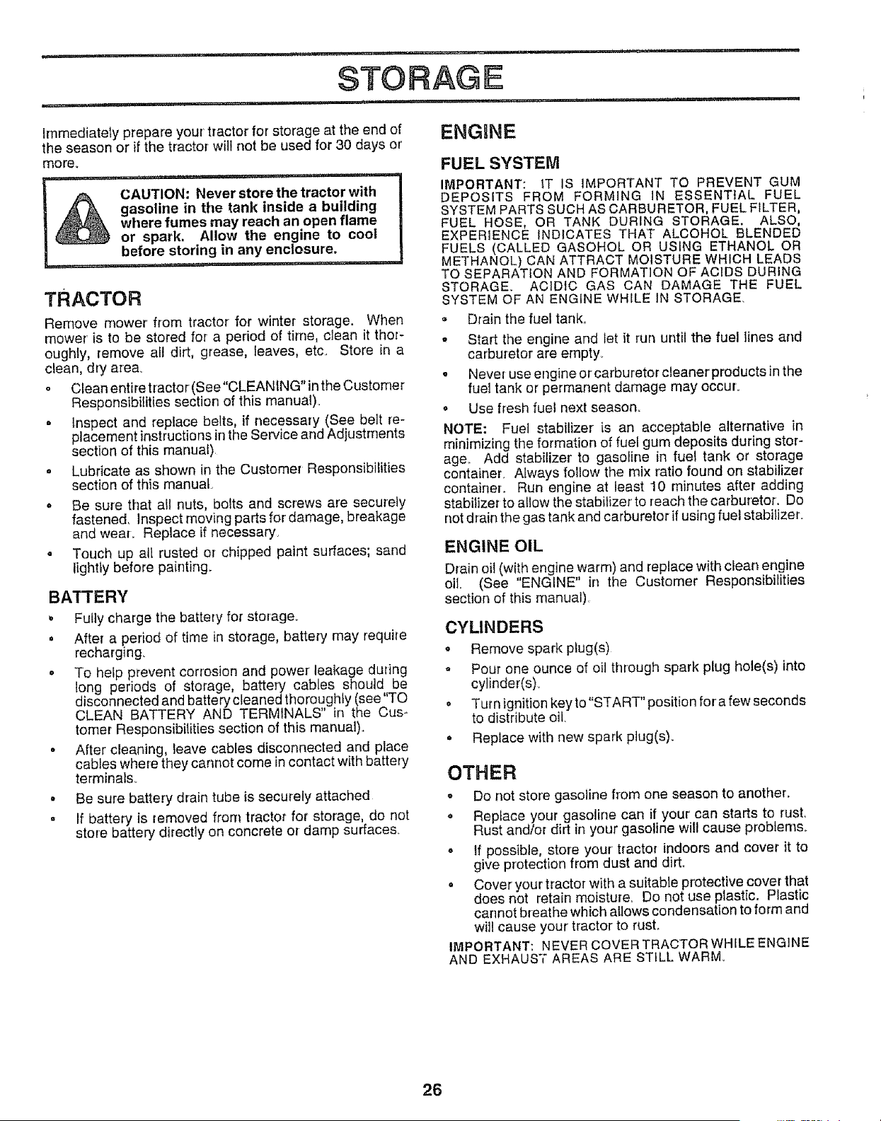
, nn:l, ,,llu ..... i,,nnl ........ i,,,,i,,i, I u ii,,u,,,ll , ,,i,,lll,ll
STORAGE
.......... in , i , i i,,ulll u,,,,n,,ir i
u'"
Immediatety prepare your tractor for storage at the end of ENGINE
the season or if the tractor will not be used for 30 days or
moreo
,, i,u , i,,, lu ,,
CAUTION: Never store the tractor with
gasoline in the tank inside a building
where fumes may reach an open flame
or spark. Allow the engine to cool
before storing in any enclosure.
,ul,,N, i " i'" "" "u
TRACTOR
Remove mower from tractor for winter storage. When
mower' is to be stored for a period of time, clean it thor-
oughly, remove all dirt, grease, leaves, etc. Store in a
clean, dry are&
o Clean entire tractor (See"CLEANING" in the Customer
Responsibilities section of this manual).
o Inspect and replace belts, if necessary (See belt re-
placement instructions in the Service and Adjustments
section of this manual)
o Lubricate as shown in the Customer Responsibilities
section of this manual
• Be sure that all nuts, bolts and screws are securely
fastened. Inspect moving parts for damage, breakage
and wear. Replace if necessary,
° Touch up all rusted or chipped paint surfaces; sand
lightly before painting_
BATI'ERY
Fully charge the battery for storage.
o After a period of time in storage, battery may require
recharging.
o To help prevent corrosion and power leakage during
ong periods of storage, battery cables should be
disconnected and battery cleaned thoroughly (see TO
CLEAN BATTERY AND TERMINALS" in the Cus_
tomer Responsibilities section of this manual).
o After cleaning, leave cables disconnected and place
cables where they cannot come in contact with battery
terminals°
• Be sure battery drain tube is securely attached
• If battery is removed from tractor for storage, do not
store battery directly on concrete or damp surfaces.
FUEL SYSTEM
IMPORTANT: iT IS IMPORTANT TO PREVENT GUM
DEPOSITS FROM FORMING iN ESSENT{AL FUEL
SYSTEM PARTS SUCH AS CARBURETOR, FUEL FILTER,
FUEL HOSE, OR TANK DURING STORAGE. ALSO,
EXPERIENCE INDICATES THAT ALCOHOL BLENDED
FUELS (CALLED GASOHOL OR USING ETHANOL OR
METHANOL) CAN ATTRACT MOISTURE WHICH LEADS
TO SEPARATION AND FORMATION OF ACIDS DURING
STORAGE. ACIDIC GAS CAN DAMAGE THE FUEL
SYSTEM OF AN ENGINE WHILE tN STORAGE.
,, Drainthe fueltank_
. Start the engine and let it run until the fuel lines and
carburetor are empty.
o Never use engine or carburetor cleaner products in the
fuel tank or permanent damage may occur.
,, Use fresh fuel next season.
NOTE: Fuel stabilizer is an acceptable alternative in
minimizing the formation of fuel gum deposits during stor-
age_ Add stabilizer to gasoline in fuel tank or storage
containeL Always follow the mix ratio found on stabilizer
container. Run engine at least 10 minutes after adding
stabilizer to allow the stabilizer' to reach the carburetor. Do
not drain the gas tank and carburetor if using fuel stabilizer.
ENGINE OIL
Drain oil (with engine warm) and replace w{th clean engine
oil, (See "ENGINE" in the Customer Responsibilities
section of this manual)
CYLINDERS
• Remove spark plug(s)
o Pour one ounce of oil through spark plug hole(s) into
cylinder(s).
° Turn ignitionkeyto"START" position fora few seconds
to distribute oil.
• Replace with new spark piug(s).
OTHER
o Do not store gasoline fiom one season to another.
o Replace your gasoline can if your can starts to rust.
Rust and/or dirt in your gasoline will cause problems°
. If possible, store your tractor indoors and cover it to
give protection from dust and dirt.
• Cover your tractor with a suitable protective cover that
does not retain moisture. Do not use plastic. Plastic
cannot breathe which allows condensation to form and
will cause your tractor to rusL
IMPORTANT: NEVER COVER TRACTOR WHILE ENGINE
AND EXHAUST AREAS ARE STILL WARM
26

i i.....i, i . ... i i i. i.i.n. I ....................................... r I ,nlu. i n
TROUBLESHOOTING POaNTS
,i ,i,ii,, i , ,i ii i i iiq i, r,l,l,,i ,i, iii ,i,_ i ii i i iii,
CAUSE CORRECTION
PROBLEM
Will not start
Hard to start
u, i
Engine w_ll not turn over
Engine clicks but will not
start
...................i,i
Lossofpewer
Excessive vibration
1 Out of rue!
2. Engine not "CHOKED" properly
3 Engine flooded
4 Bad spark plug
5 Dirt] air filter
6 Dirty fuel filter
7. Water in fuel.
8 Loose or damaged wiring.
9 Carburetor out of adjustment
10 Engine valves out of adjustment
1 Dirty air fiiter.
2 Badspark plug
3 Weak or dead battery.
4. Dirty fuef filter
5 Stale or dirty fuel
6 Loose or damaged wiring
7 Carburetor out of adiustmenl
8 Engine valves out of adjustment
.- ....................... i.u.. i
1 Clutch/brake pedal not depressed.
2 Attachment clutch is engaged
3 Weak ordead battery.
4 Blown fuse..
5 Corroded battery terminals.
6 Loose or damaged wiring
7 Faulty ignition switch
8. Fautty solenoid or starter
9 Fau]tyoperator presence switch(SS)r
1 Weak or dead battery
2 CorToded battery terminals
3 Loose or damaged wiring.
4 Faulty solenoid or starter
1 Cutting too much grassttoo fast..
2 Throttle in "CHOKE" position
3 Build-up of grass, leaves and trash under mower.
41 Dirty air filter.
5 Low oil level!dirty oil,
6 Faulty spark plug
7 Dirty fuel filter,
8 Stale or dtdy fuel
9 Water in fuel
10 Spark plug wire loose.
11 Dirty engine air screen/fins
12 Dirty/c{egged muffler.
13 Loose or damaged wiring.
14 Carburetor out of adjustment.
15. Engine valves out of adjustment
.... ii.
1 Worn, bent or loose blade
2 Bent blade mandrel
3 Loose/damaged part(s).
1 Fill fuel tank
2 See "TO START ENGINE" fn Operation section.
3 Wait several minutes before attempting to start
4. Replace spark plug.
5 C_eanireplace air filler.
6. Replace fuel filter
7 Drain fuel tank and carburetor, refill lank with fresh
gasoiine and replace fue_ litter
8 Check eli wiring
9 See "To Adjust Carburetor" in Service Adjustments
secfiOnr
f 0o Contact an authorized service center/department..
1_ Clean/replace air filter
2,, Replace spark plug
3 Recharge or replace battery.
4 Replace fuel filter
5 Drain tue_tank and refill with fresh gasoline.
6 Check all wiring
7 See "To Adjust Carburetor" in Service Adjustments
section
8. Contact an au{hodzed service canter/department.
irl,ll., i
1 Depress clutch/brake pedal.
2 Disengage attachment clutch
3 Recharge or replace battery•.
4 Replace fuse
5. Clean battery terminals
6. Check alEwiring
7. Check/replace ignition switch.
8 Check/replace solenoid or starter.
9 Contact an authorized service center/department
t Recharge or replace battery
2 Clean battery terminals
3. Check ell wiring.
4. Check/replace solenoid or starter°
l r Set in "Higher Cut" posifionlreduce speed,
21 Adjust throttle contro_
3 Clean underside of mower housing,,
4, Clean/replace air filter,
5 Check oil teve]/change oi]
6. Clean and regap or change spark piug
7 Replacs fuel filter
B Drain fuel tank and refill with fresh gasoline.
9. Drain fuel tank and carburetor, refill tank with fresh
gasoline and replace fuel filter.
10. Connect and tighten spark plug wire.
11 Clean engine air screentfins
12 Clean/replace muffler.
13 Check aIEwiring
t4. See "To Adjust Carburetor" in Service Adjustments
sect{on
15 Contact an authorized service center/department
1.
2
3
Replace blade Tighten blade bolt
Replace blade mandrei
Tighten loose part(s), Reprace damaged parts
27

' ,i ,,11,,-i ........ i,i i i,i1,,,i,1,111,111-1¸ , i i iii i,,i,i i1,,,i
TROUBL HOOTING POINTS
.................. i, i iiiiiiiiiii ii
PROBLEM
ii i, i1,1,
Engine continues to run
when operator leaves seat
with attachment clutch
engaged
Poor cut - uneven
i1,1i,,iiil,l,i
Mower blades will not
rotate
Poor grass discharge
i, ,11,,,-i
Headlight(s) not working
(if so equipped)
Battery will not charge
Engine "bacldires"
when turning engine
"OFF"
CAUSE
...... ii1,111,11,11,, ,,i ,i i,,i,1,,,i, i.....
t Faulty operator-safety presence control system.
i,, ,i,,i,, i- i,, ,,111111,
1 Worn, bent or loose blade.
2 Mower deck net levet
3 Buitdup of grass, Ieaves, and trash under mower.
4 Bent blade mandrel.
5 C_ogged mower deck vent holes from bulldup of
grass, leaves, and trash around mandrels.
1 Obstruction in clutch mechanism
2 Womldamaged mower drive belt
3 Frozen idler pulley..
4 Frozen blade mandre_
t Engine speed too slow.
2 Travel speed too fast
3 Wet grass,
4 Mower deck not level
5, Lowtuneven tire air pressure
6 Worn, bent or loose blade
7, Buildup of grass, leaves and trash under mower
8 Mower drive belt worn
9 Blades improperly installed.
10 improper blades used.
11 Clogged mower deck vent holes from but{dup of
grass, leaves, and trash around mandrels
t Switch is "OFF"
2 Bulb(s) burned out
3 Faulty tight switch.
4 Loose or damaged wiring
5. Brown fuse
1 Bad battery cell(s)
2 Poor cabIe connections
3 Faulty regulator (if so equipped)
4. Faulty alternator.
l. Engine thrott{e control not set at "SLOW"
position for 30 seconds before stopping engine
CORRECTION
1 Checkwiring, switches and connections, If not
corrected, contact an authorized service center/
department
i i i i, iii iiiii1,1,,,iiiiiii
1 Replace blade Tighten blade bott.
2. Level mower deck
3 Clean underside of mower housing
4 Rspiace blade mandrel,
5 Clean around mandrels to open vent holes_
Remove obstruction
2 Replace mower drive bert.
3 Replace idler puItey
4 Replace bJade mandret
t Place throttle control in "FAST" position.
2 Shift to slower speed.
3. AlJow grass to dry before mowing.
4 Levei mower deck
5 Checktires for proper air pressure.
6 Replace/sharpen blade Tighten blade boll
7 Clean underside of mower housing.
8 Replace mower d_ive belt
9 Reinstall blades sharp edge down.
t0. Replace with btades listed in this manual
11 Ciean around mandrels to open vent holes
1 Turn switch "ON"
2 Replace bulb(s)
3 Checidteptace light switch
4. Check wiring and connections
5 Replace fuse
1 Replace battery
2 Check/clean all connectioes_
3 Rep!ece regulator
4 Replace alternator.
Move throttte control to "SLOW" position and allow
to idle for 30 seconds before stopping engine.
28
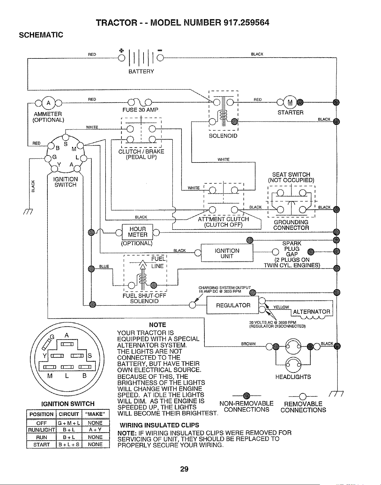
TRACTOR -- MODEL NUMBER 917.259564
SCHEMATIC
llt-
0E0 o111o 0LAc.
BATTERY
IGNITION SWITCH
POSITION CIRCUIT "MAKE"
OFF G + M + L NONE
RUN/LIGHT B + L A + Y
RUN B + L NONE
START S + L + S NONE
NOTE
YOUR TRACTOR IS
EQUIPPED WITH A SPECIAL
ALTERNATOR SYSTEM.
THE LIGHTS ARE NOT
CONNECTED TO THE
BATTERY, BUT HAVE THEIR
OWN ELECTRICAL SOURCE°
BECAUSE OF THIS, THE
BRIGHTNESS OF THE LIGHTS
WILL CHANGE WITH ENGINE
SPEED. AT IDLE THE LIGHTS
WILL DIM. AS THE ENGINE IS
SPEEDED UP, THE LIGHTS
30 VOLTS AC @ 3600 RPM
(REGULATOR DISCONNECTED)
BROWN
HEADLIGHTS
@ 0 '_'
NON-REMOVABLE REMOVABLE
CONNECTIONS CONNECTIONS
WILt. BECOME THEIR BRIGHTEST°
WIRING INSULATED CLIPS
NOTE: IF WIRING INSULATED CLIPS WERE REMOVED FOR
SERVICING OF UNIT, THEY SHOULD BE REPLACED TO
PROPERLY SECURE YOUR WIRING.
29
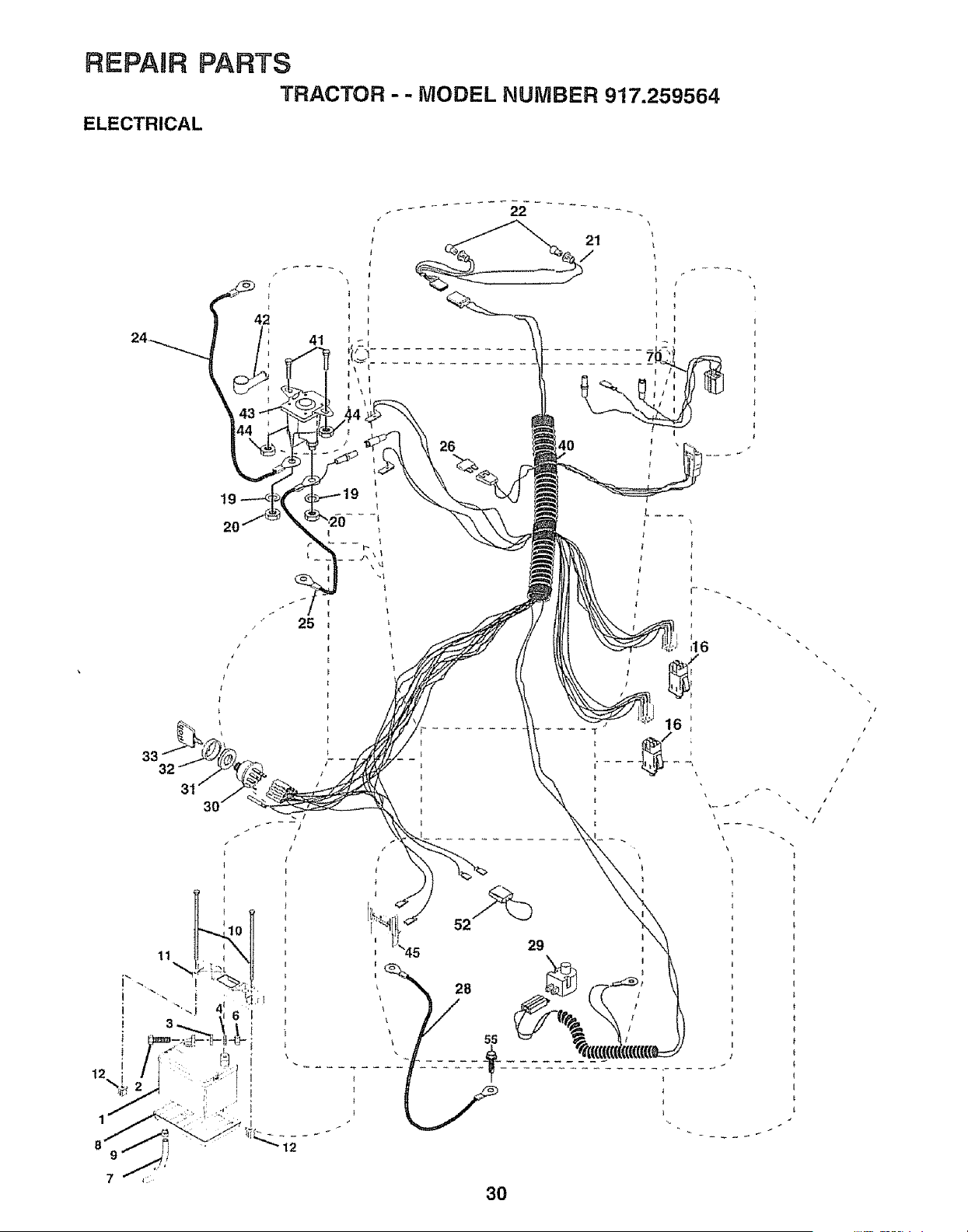
REPABR PARTS
TRACTOR -- MODEL NUMBER 917.259564
ELECTRICAL
t9
20
33
25
x
3O
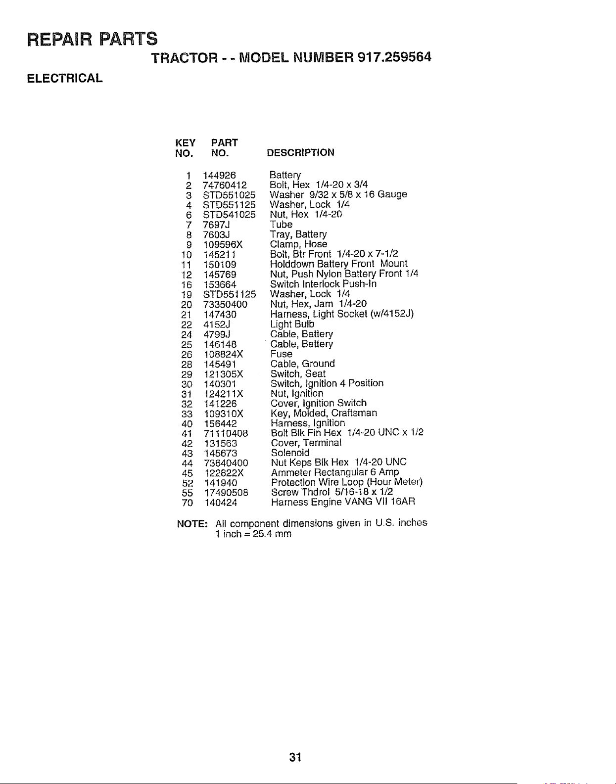
REPAaR PARTS
TRACTOR - - MODEL NUMBER 917.259564
ELECTRICAL
KEY PART
NO. NO. DESCRIPTION
1 144926
2 74760412
3 STD551025
4 STD551125
6 STD541025
7 769_J
8 7603J
9 109596X
10 145211
11 15O1O9
12 145769
16 153664
19 STD551125
20 73350400
21 14743O
22 4152J
24 4799J
25 146148
26 108824X
28 145491
29 12!305X
30 1403O1
31 124211X
32 141226
33 t09310X
40 156442
41 71110408
42 131563
43 145673
44 73640400
45 I22822X
52 141940
55 17490508
7O 140424
Battery
Bolt, Hex 1/4-20 x 3/4
Washer 9/32 x 5/8 x 16 Gauge
Washer, Lock 1/4
Nut, Hex 1/4-20
Tube
Tray, Battery
Clamp, Hose
Bolt, Btr Front 1/4-20 x 7-1/2
Holddown Battery Front Mount
Nut, Push Nylon Battery Front 1/4
Switch Interlock Push-ln
Washer, Lock 1/4
Nut, Hex, Jam 1/4-20
Harness, Light Socket (w/4152J)
Light Bulb
Cable, Battery
Cable, Battery
Fuse
Cable, Ground
Switch, Seat
Switch, tgnition 4 Position
Nut, Ignition
Cover, Ignition Switch
Key, Molded, Craftsman
Harness, Ignition
Bolt Blk Fin Hex 1/4-20 UNC x 1/2
Cover, Terminal
Solenoid
Nut Keps Blk Hex 1/4-20 UNC
Ammeter Rectangular 6 Amp
Protection Wire Loop (Hour Meter)
Screw Thdrol 5/16-16 x t/2
Harness Engine VANG VII 16AR
NOTE: All component dimensions given in USo inches
I inch = 25_4 mm
31
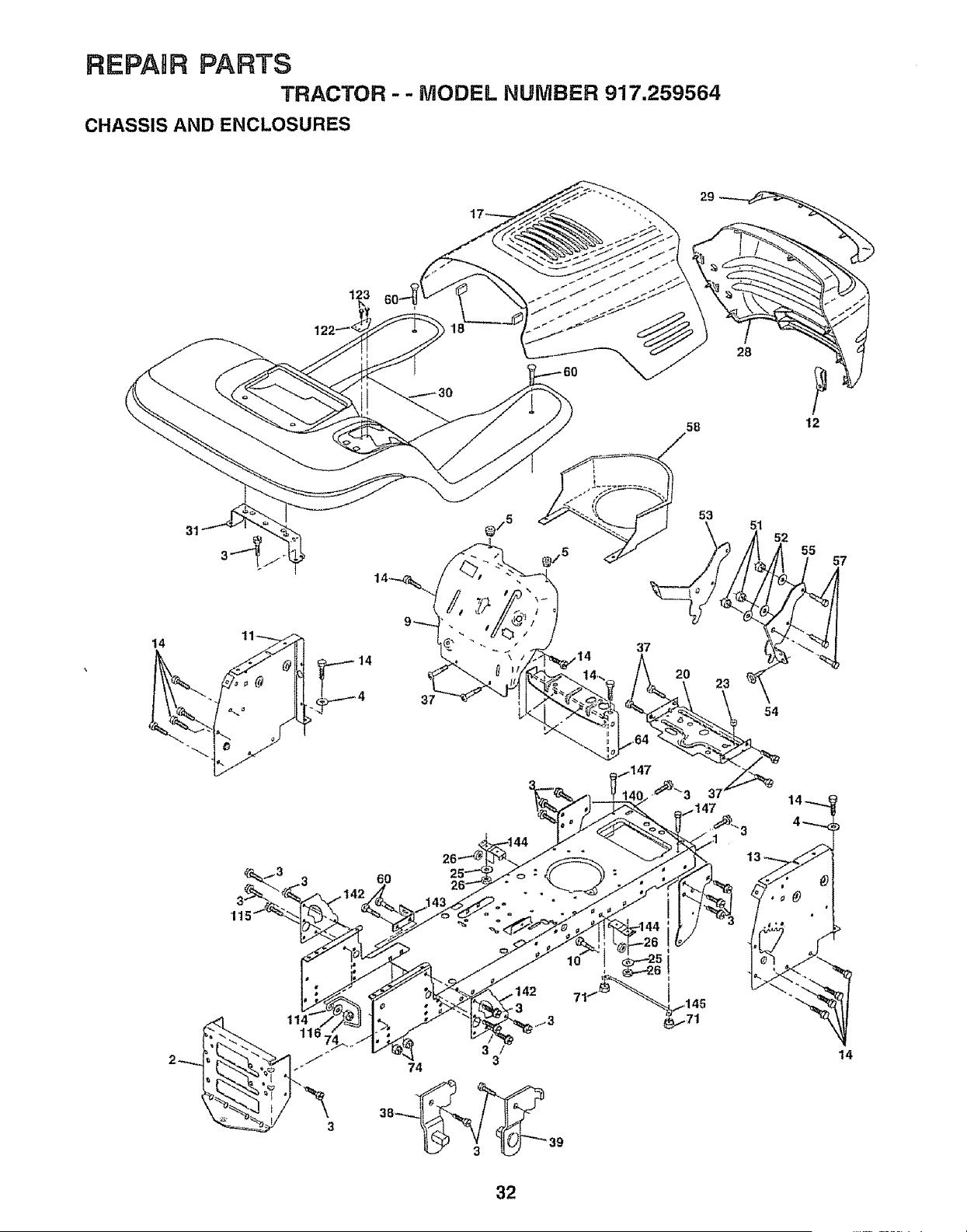
REPAIR PARTS
TRACTOR - - MODEL NUMBER 917.259564
CHASSIS AND ENCLOSURES
28
58 12
14
14
37
14
32

REPARRPARTS
TRACTOR - - MODEL NUMBER 917.259564
CHASSIS AND ENCLOSURES
KEY PART
NO. NO. DESCRIPTION
1 159527
2 140356
3 17490612
4 STD551025
5 155272
9 150156X011
10 STD533710
11 155927
t2 145660
13 155936
14 17490608
I7 144983X558
I8 126938X
20 '156437
23 124028X
25 19131312
26 STD541437
28 145198X558
29 155217
30 151287X558
31 139976
37 1749O5O8
38 139886
39 139887
51 73800400
52 19091416
53 145201
54 17030814
55 1452O2
57 STD552507
58 150127
60 7214O6O6
64 '154798
71 73680400
74 STD541437
1t4 158112
115 17490620
116 19131614
122 1573O1
123 152927
140 158416
142 156095
143 154966
t44 154207
145 156524
147 74760412
Chassis
Drawbar
Screw, Thd., Roll. 3/8-16 x 3/4 Type TT
Washer !3/32 x 3/4 x 16 Gauge
Bumper Hood/Dash
Dash, Si_kscreened
Bolt, Carriage 3/8-16 x 1
Panel, Dash, LH
Clip Tinnerman Grille P/L
Panel, Dash, RH
Screw, Thd., Roll. 3/8-16 x 1/2 Type TT
Hood Assembly
Bumber Hood
Ptate Mtg Battery Fuel Tank
Bushing, Snap, Nylon, Fuel Line
Washer 13/32 x 13/16 x 12 Gauge
Locknut, Hex, with Insert 3/8-16 UNC
Grille, W/Clips M8-558
Lens, Grille
Fender/Footrest
Bracket, Fender/Support
Screw, Thdrol. 5/16-18 x 1/2 TYT
Pivot Bracket Assembly, LH, Mower, Rear
Pivot Bracket Assembly, RH, Mower, Rear
Nut Lock W/Insert 1/4 - 20 UNC
Washer 9/32 X 7/8 X 16 Ga.
Bracket Grille Pickoff LH
Screw, Hex Head, Spiderlock #8 x 7/8 AB
Bracket Grille Pickoff RH
Bolt FinHex 1/4 -20 UNC X.75
Duct Air Engine PL/LT
Bott Rdhd Sqnk 3/8-16 UNC x 3/4
Dash Lower STLT
Nut Crownlock 1/4-20 UNC
Nut Crownlock 3/8-16 UNC
Keeper Belt Rear LH
Screw Thdrol 3/8-t6 x t-I/4
Washer 13/32 x 1 x 14 Ga.
Bracket Shift STLT
Screw
Bracket Suspension Front
Plate Reinforcement STLT
Backrest Swaybar Chassis
Bracket Footrest STLT
Rod Pivot Chassis/Hood
Bolt Hex Hd 1/4-20 UNC x 3/4
NOTE: All component dimensions given in U.S. inches
1 inch = 25.4 mm
33
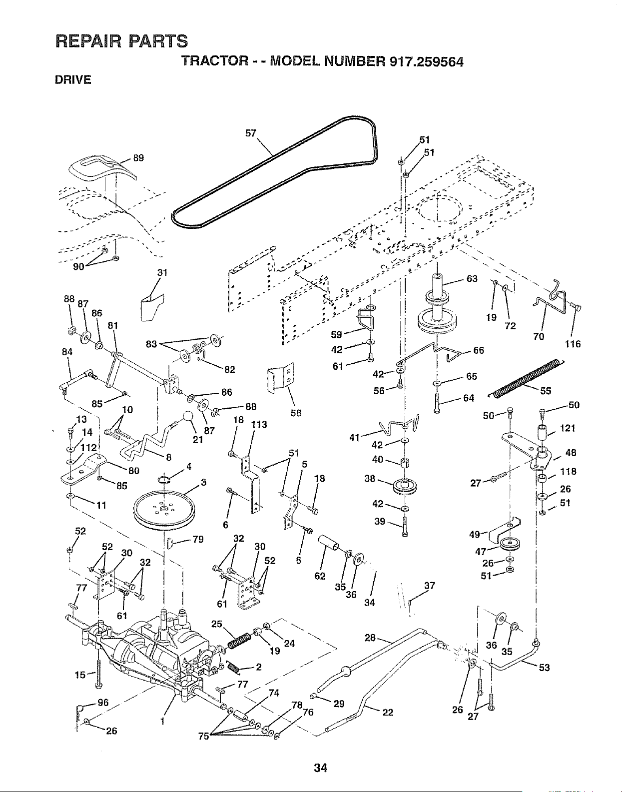
REPAIR pARTS
TRACTOR " - MODEL NUMBER 917.259564
DRIVE
31
88 87
86
81
84
57
85
13
10
87
21
58
18 113
51
5
18
6t
56
6
32
121
34
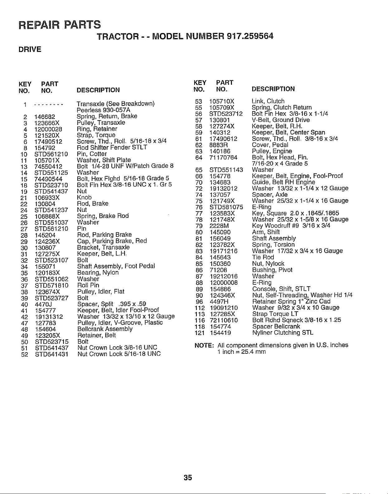
REPAIR PARTS
TRACTOR -- MODEL NUMBER 917,259564
DRIVE
KEY PART KEY PART
NO. NO. DESCRIPTION NO. NO. DESCRIPTION
1 ........ Transaxle (See Breakdown) 53 105710X
Peerless 930-057A 55 105709X
2 146682 Spring, Return, Brake 56 STD523712
3 123666X Pulley, Transaxle 57 130801
4 12000028 Ring, Retainer 58 127274X
5 12!520X Strap, Torque 59 140312
6 17490512 Screw, Thd., Roll 5/16-18 x 3/4 61 17490612
8 154792 Rod Shifter Fender STLT 62 8883R
10 STD561210 Pin, Cotter 63 140186
11 105701X Washer, Shift Plate 64 71170764
13 74550412 Bolt 1/4-28 UNF W/Patch Grade 8
14 STD551125 Washer 65 STD551143
15 74490544 Bolt, Hex Flghd 5/16-18 Grade 5 66 154778
18 STD523710 Bolt Fin Hex 3/8-16 UNC X 1_ Gr 5 70 134683
19 STD541437 Nut 72 19132012
21 106933X Knob 74 137057
22 130804 Rod, Brake 75 '121749X
24 STD541237 Nut 76 STD581075
25 106888X Spring, Brake Rod 77 t23583X
26 STD551037 Washer 78 121748X
27 STD561210 Pin 79 2228M
28 145204 Rod, Parking Brake 80 145090
29 124236X Cap, Parking Brake, Red 81 156049
30 130807 Bracket, Transaxle 82 123782X
31 127275X Keeper, Belt, L.Hr 83 19171216
32 STD523107 Bolt 84 145643
34 15507t Shaft Assembly, Foot Pedal 85 150350
35 120'!83X Bearing, Nylon 85 71208
36 STD551052 Washer 87 19212016
37 STD571810 Roll Pin 88 12000008
38 123574X Pulley, Idler, Flat 89 154886
39 STD523727 Bolt 90 124346X
40 4470J Spacer, Split .395 x.59 96 4497H
41 154777 Keeper, Beft, Idler Foot-Proof 112 19091210
42 19131312 Washer 13/32 x13/16 x12 Gauge 113 127285X
47 127783 Pulley, Idler, V-Groove, Plastic 116 72110610
48 154604 Bellcrank Assembly 118 154774
49 123205X Retainer, Belt 121 154419
50 STD523715 Bolt
51 STD541437 Nut Crown Lock 3/8-16 UNC
52 STD541431 Nut Crown Lock 5/16-18 UNC
Link, Clutch
Spring, Clutch Return
Bolt Fin Hex 3/8-16 x ld/4
V-Belt, Ground Drive
Keeper, Belt, R_H.
Keeper, Bett, Center Span
Screw, Thdo, Roll. 3/8-16 x 3/4
Cover, Pedal
Pulley, Engine
Bolt, Hex Head, Fin.
7/16-20 x 4 Grade 5
Washer
Keeper, Belt, Engine, Fool-Proof
Guide, Belt RH Engine
Washer 13/32 x 1_1/4 x 12 Gauge
Spacer, Axle
Washer 25/32 x 1-1/4 x t6 Gauge
E-Ring
Key, Square 2°0 x .1845/.1865
Washer 25/32 x 1-5/8 x 16 Gauge
Key Woodruff #9 3/16 x 3/4
Arm, Shift
Shaft Assembly
Spring, Torsion
Washer 17/32 x 3/4 x 16 Gauge
Tie Rod
Nut, Nylock
Bushing, Pivot
Washer
E-Ring
Console, Shift, STLT
Nut, Self-Threading, Washer Hd 1/4
Retainer Spring 1" Zinc Cad
Washer 9/32 x 3/4 x 10 Gauge
Strap Torque LT
Bolt Rdhd Sqneck 3/8-16 x 1_25
Spacer Bellcrank
Nyliner Clutching STL
NOTE: All component dimensions given in U,So inches
t inch = 25.4 mm
35
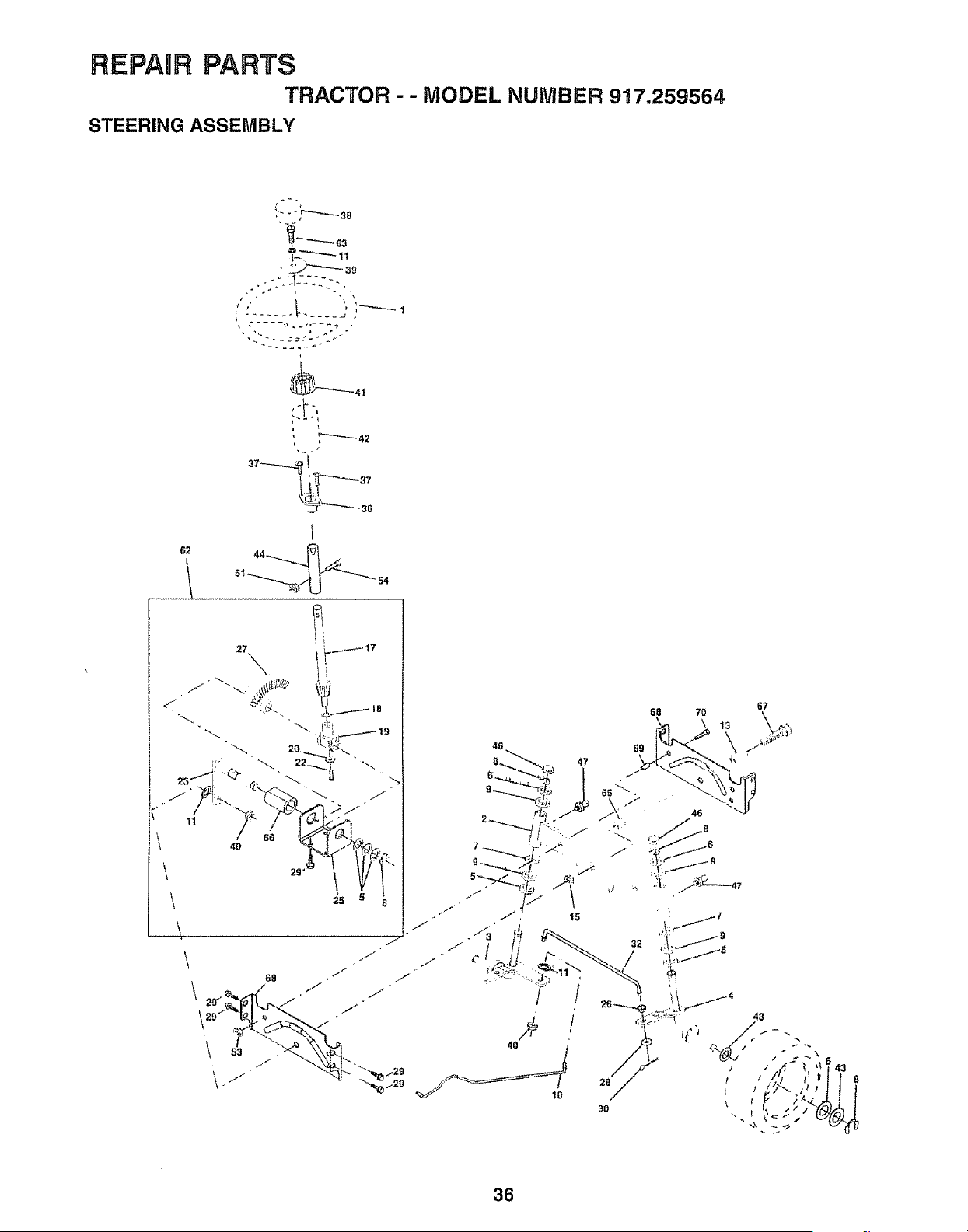
REPAIR PARTS
TRACTOR - - MODEL NUMBER 917.259564
STEERING ASSEMBLY
!_'_ 63
_L'--'....,.,.._ 11
: • IF * _
25
\
67
32
28
30
36
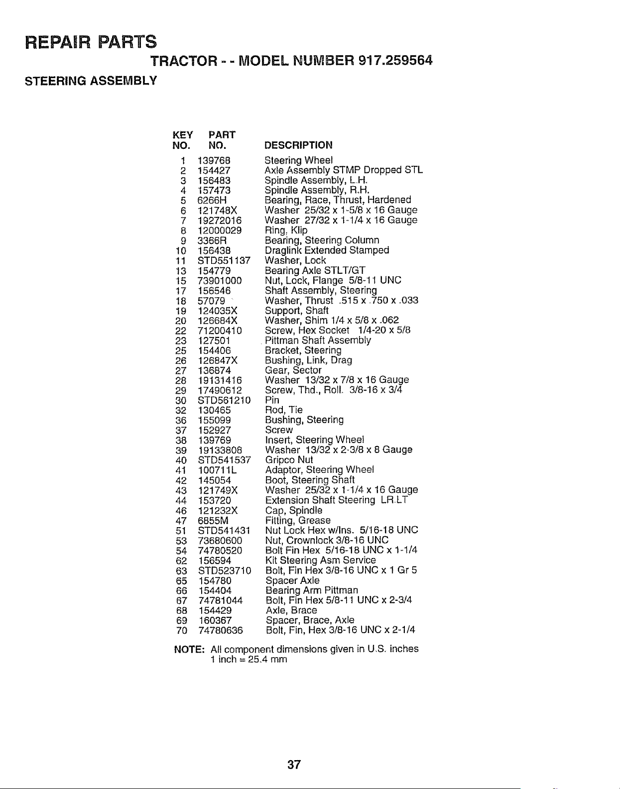
REPAIR PARTS
TRACTOR =- MODEL NUMBER 917.259564
STEERING ASSEMBLY
KEY PART
NO. NO.
1 139766
2 154427
3 156483
4 157473
5 6266H
6 121748X
7 19272016
8 12000029
9 3366R
10 156438
tl STD551137
13 154779
15 73901000
17 156546
18 57079
19 124035X
20 126684X
22 71200410
23 127501
25 154406
26 126847X
27 136874
28 19131416
29 17490612
30 STD561210
32 130465
36 155099
37 152927
38 139769
39 19133808
40 STD541537
41 100711L
42 145054
43 12!749X
44 153720
46 121232X
47 6855M
51 STD541431
53 73680600
54 74780520
62 156594
63 STD523710
65 154780
66 154404
67 74781044
66 154429
69 160367
70 74780636
DESCRIPTION
Steering Wheel
Axle Assembly STMP Dropped STL
Spindle Assembly, LH,
Spindle Assembly, Roll.
Bearing, Race, Thrust, Hardened
Washer 25/32 x 1-5/8 x 16 Gauge
Washer 27/32 x 1-1/4 x t6 Gauge
Ring_ Ktip
Bearing, Steering Column
Draglink Extended Stamped
Washer, Lock
Bearing Axle STLT/GT
Nut, Lock, Flange 5/8-11 UNC
Shaft Assembly, Steedng
Washer, Thrust 515 x 750 x _033
Support, Shaft
Washer, Shim 1/4 x 5/8 x _062
Screw, Hex Socket 1/4-20 x 5/8
Pittman Shaft Assembiy
Bracket, Steering
Bushing, Link, Drag
Gear, Sector
Washer 13/32 x 7/8 x 16 Gauge
Screw, Thd. Rol! 3/8-16 x 3/4
Pin
Rod, Tie
Bushing, Steering
Screw
Insert, Steering Wheel
Washer 13/32 x 2-3/8 x 8 Gauge
Gripco Nut
Adaptor, Steering Wheel
Boot, Steering Shaft
Washer 25/32 x 1-1/4 x 16 Gauge
Extension Shaft Steering LRLT
Cap, Spindle
Fitting, Grease
Nut Lock Hex w/Ins. 5/16-18 UNC
Nut, Crownlock 3/8-16 UNC
Bolt Fin Hex 5/16-18 UNC x 1-1/4
Kit Steering Asm Service
Bolt, Fin Hex 3/8-16 UNC x 1 Gr 5
Spacer Axle
Bearing Arm Pittman
Bolt, Fin Hex 5/8-11 UNC x 2-3/4
Axle, Brace
Spacer, Brace, Axle
Bolt, Fin, Hex 3/8-16 UNC x 2-1/4
NOTE: All component dimensions given in U.S inches
1 inch = 25°4 mm
37
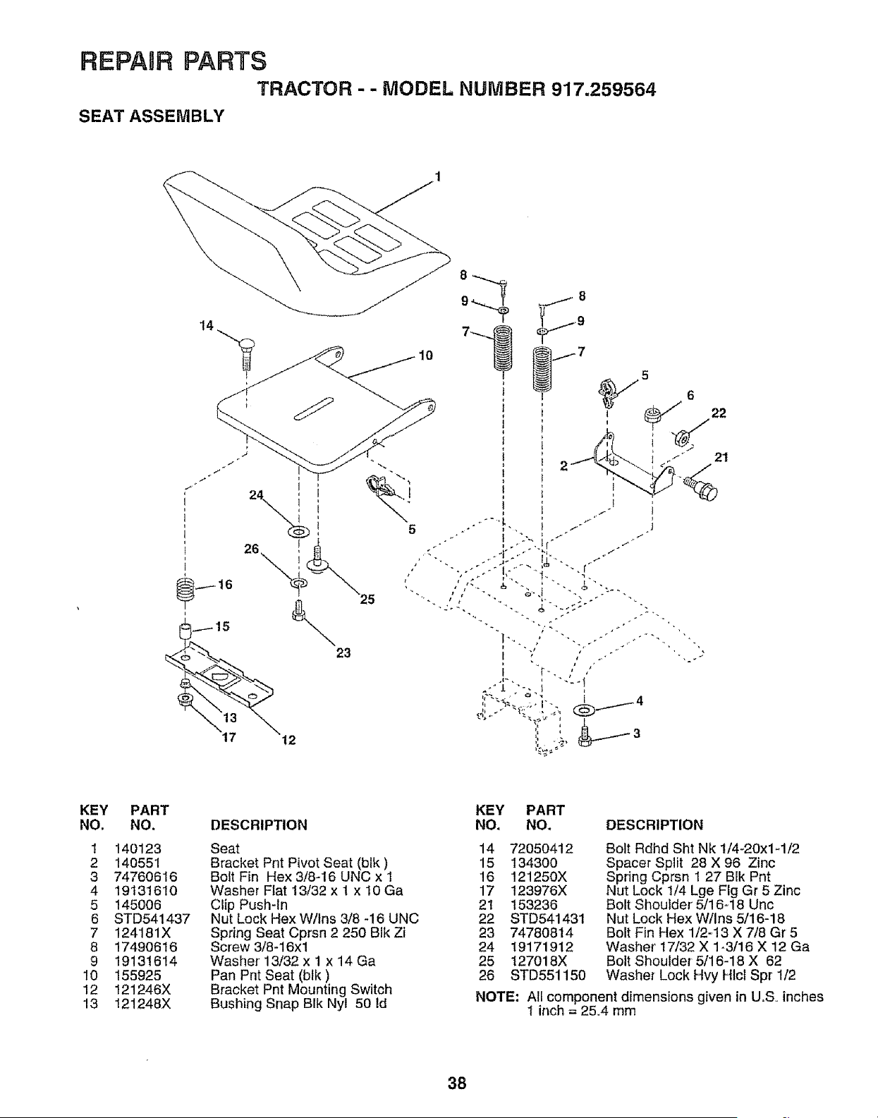
REPAIR PARTS
TRACTOR - - MODEL NUMBER 917.259564
SEAT ASSEMBLY
@
5
21
KEY
NO.
1
2
3
4
5
6
7
8
9
10
12
13
PART
NO.
140123
140551
74760616
19131610
145006
STD541437
124181X
17490616
19131614
155925
121246X
121248X
KEY PART
DESCRIPTION NO. NO.
Seat 14
Bracket Pnt Pivot Seat (blk) 15
Bolt Fin Hex 3/8-16 UNC x 1 16
Washer Flat 13/32 x I x 10 Ga 17
Clip Push-In 2!
Nut Lock Hex W/ins 3/8 -16 UNC 22
Spring Seat Cprsn 2 250 Blk Zi 23
Screw 3/8-16xl 24
Washer 13/32 x 1 x 14 Ga 25
Pan Pnt Seat (blk) 26
Bracket Pnt Mounting Switch
Bushing Snap BIk Nyl 50 Id
72050412
134300
121250X
123976X
153236
STD541431
74780814
19171912
127018X
STD551150
DESCRIPTION
Bolt Rdhd Sht Nk 1/4_20x1_1/2
Spacer Split 28 X 96 Zinc
Spring Cprsn 1 27 Blk Pnt
Nut Lock 1/4 Lge Fig Gr 5 Zinc
Bolt Shoulder' 5/16-18 Unc
Nut Lock Hex W/Ins 5/16-18
Bolt Fin Hex 1/2=13 X 7/8 Gr5
Washer' 17/32 X 1-3/16 X 12 Ga
Bolt Shoulder 5/16-18 X 62
Washer Lock Hvy Hlct Spr 1/2
NOTE: Ali component dimensions given in U.So inches
1 inch = 25_4 mm
38
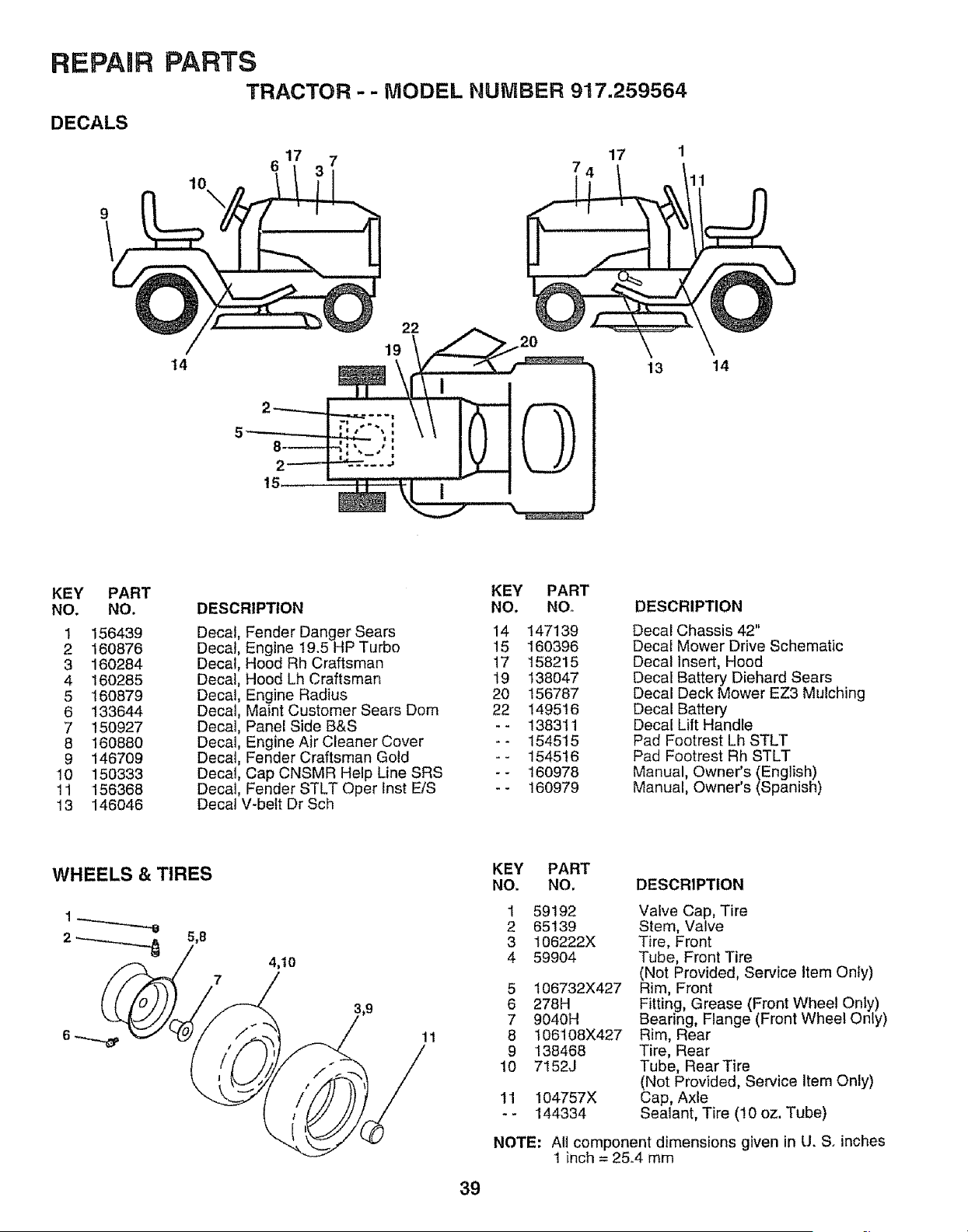
REPAIR
DECALS
PARTS
TRACTOR - - MODEL NUMBER 917.259564
10
14
7
22
19
17
\
13 14
15
KEY PART
NO. NO.
1 156439
2 160876
3 160284
4 160285
5 160879
6 133644
7 150927
8 160880
9 146709
10 150333
11 156368
13 146046
DESCRIPTION
Decal
Decal
Decal
Decal
Decal
Decal
Decal
Decal
Decal
Decal
Decal
Fender Danger Sears
Engine t9.5 HP Turbo
Hood Rh Craftsman
Hood Lh Craftsman
Engine Radius
Maint Customer Sears Dora
Panel Side B&S
Engine Air Cleaner Cover
Fender Craftsman Gold
Cap CNSMR Help Line SRS
Fender STLT Oper lnst E/S
Decal V-belt Dr Sch
KEY PART
NO, NO.
14 147139
15 160396
17 158215
19 138047
20 156787
22 149516
-- 138311
-- 154515
-- 154516
-- 160978
-- 160979
DESCRIPTION
Decal Chassis 42"
Decal Mower Drive Schematic
Decal Insert, Hood
Decal Battery Diehard Sears
Decal Deck Mower EZ3 Mulching
Decal Battery
Decal Lift Handle
Pad Footrest Lh STLT
Pad Footrest Rh STLT
Manual, Owner's (English)
Manual, Owner's (Spanish)
4,t0
7
11
KEY PART
NO, NO. DESCRIPTION
1
2
3
4
59192
65139
I06222X
59904
5 106732X427
6 278H
7 9040H
8 106108X427
9 138468
10 7152J
11 104757X
*- 144334
Vaive Cap, Tire
Stem, Valve
Tire, Front
Tube, Front Tire
RNOtProvided, Service Item Only)
im, Front
Fitting, Grease (Front Wheel Only)
Bearing, Flange (Front Wheel Only)
Rim, Rear
Tire, Rear
Tube, Rear Tire
(Not Provided, Service Item Only)
Cap, Axle
Sealant, Tire (10 oz. Tube)
NOTE: All component dimensions given in U. S. inches
1 inch = 25_4 mm
39
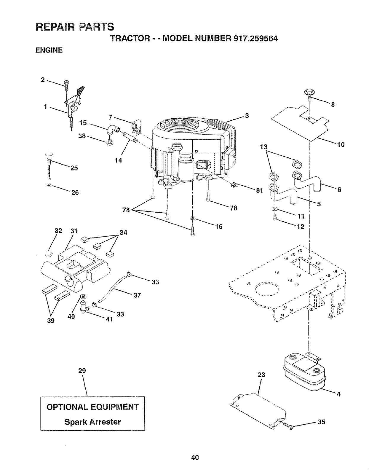
REPAIR
ENGINE
PARTS
TRACTOR -- MODEL NUMBER 917.259564
78
81
13 10
32
39 40 41 33
16
_x _ t t
29
OPTIONAL EQUIPMENT
Spark Arrester
23
35
4O
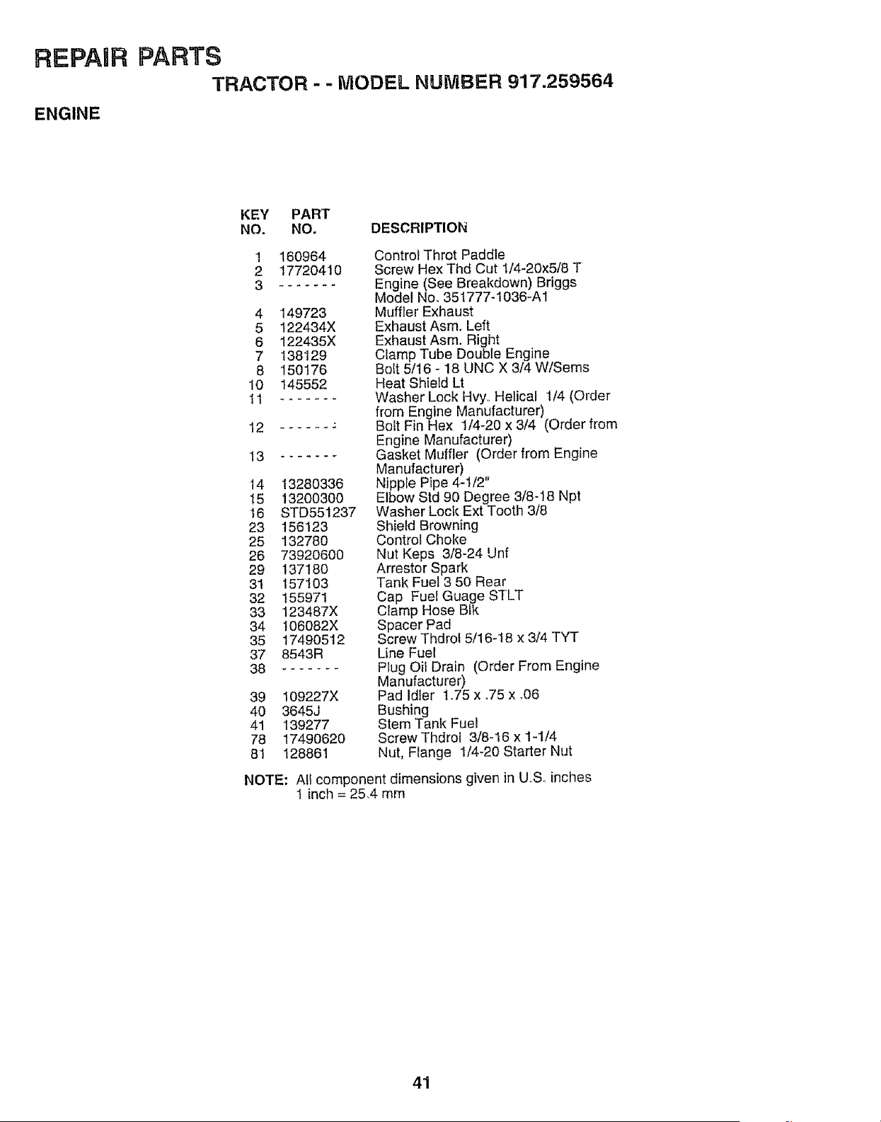
REPAUR
ENGINE
PARTS
TRACTOR - - MODEL NUMBER 917.259564
KEY PART
NO. NO. DESCRIPTION
1 160964
2 17720410
......
4 149723
5 122434X
6 122435X
7 138129
8 150176
10 145552
!1 .......
2 ......
13
f4 13280336
15 13200300
16 STD551237
23 156123
25 132780
26 73920600
29 137180
31 157103
32 155971
33 t23487X
34 t06082X
35 17490512
37 8543R
38 .......
39 109227X
4O 3645J
41 139277
78 17490620
81 128861
Control Throt Paddle
Screw Hex Thd Cut I/4-20x5/8 T
Engine (See Breakdown) Briggs
Model No. 35t777-1036-A1
Mufffer Exhaust
Exhaust Asm. Left
Exhaust Asm. Right
Clamp Tube Double Engine
Bolt 5/16 _ 18 UNC X 3/4 W/Sems
Heat Shield Lt
Washer Lock Hvy._Helical 1/4 (Order
from Engine Manufacturer)
Bolt Fin Hex 1/4-20 x 3/4 (Order from
Engine Manufacturer)
Gasket Muffler (Order from Engine
Manufacturer)
Nippte Pipe 4-1/2"
Elbow Std 90 Degree 3/8-18 Npt
Washer Lock Ext Tooth 3/8
Shield Browning
Control Choke
Nut Keps 3/8-24 Unf
Arrestor Spark
Tank Fuel 3 50 Rear
Cap Fuel Guage STLT
Clamp Hose Bik
Spacer Pad
Screw Thdrof 5/16-18 x 3/4 TYT
Line Fuel
Plug Oil Drain (Order From Engine
Manufacturer)
Pad Idler 1o75 x °75 x °06
Bushing
Stem Tank Fuel
Screw Thdrol 3/8-16 x 1-1/4
Nut, Flange 1/4-20 Starter Nut
NOTE: All component dimensions given in U,,Soinches
1 inch = 25,4 mm
4'1
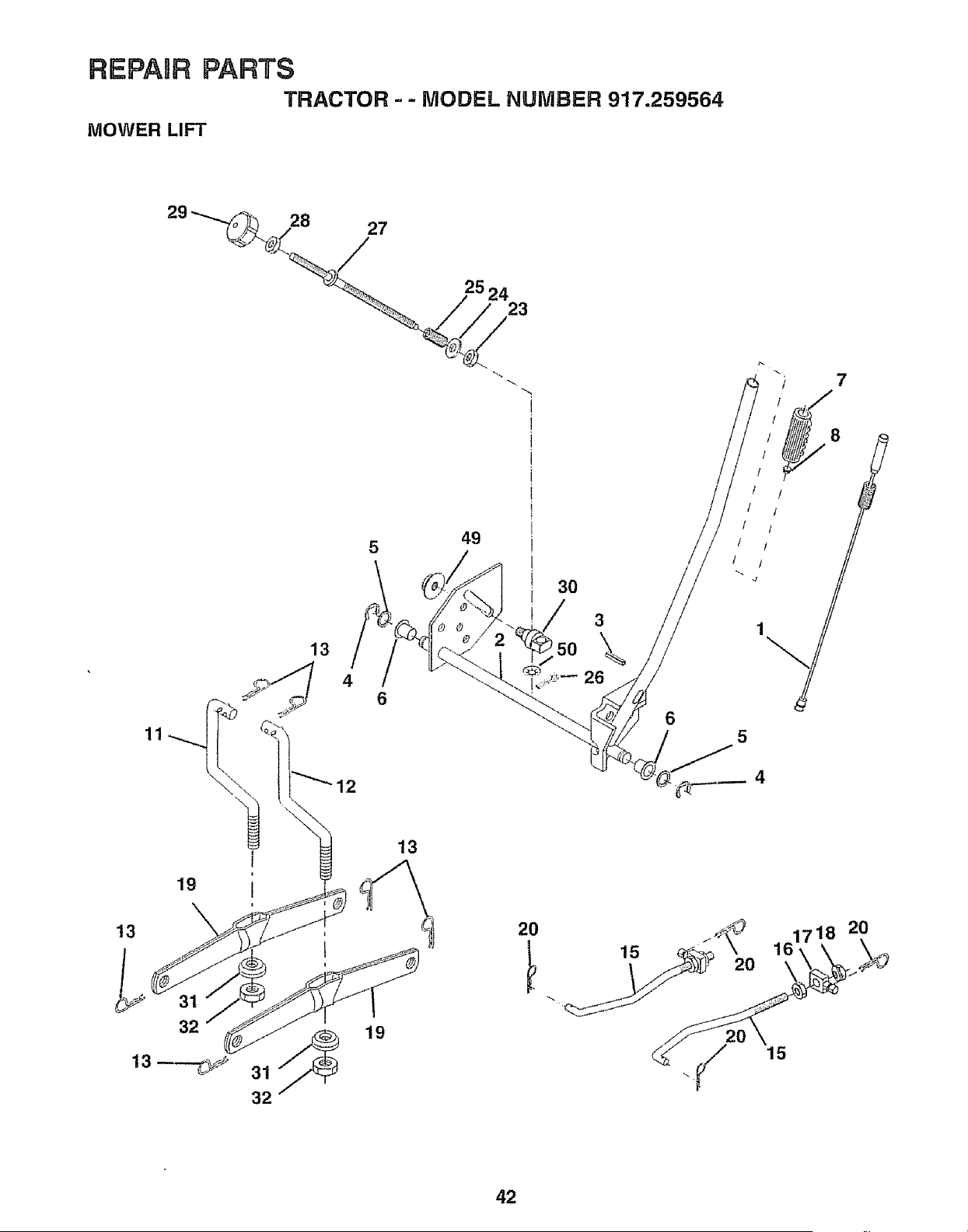
RIEPAJRPARTS
TRACTOR - - MODEL NUMBER 917.259564
MOWER LIFT
5
4
6
49
3O
3
\
26
6
8
I 1
f /
/ 1
t l
t"i
5
32
13
19
20
15
20
15
42
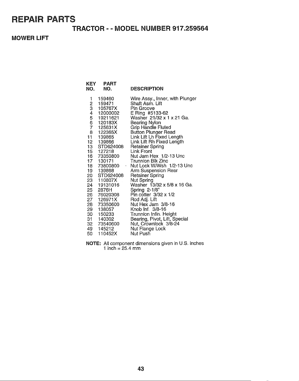
REPAUR PARTS
TRACTOR -- MODEL NUMBER 917.259564
MOWER LIFT
KEY PART
NO. NO. DESCRIPTION
1 159460
2 159471
3 105767X
4 120OOOO2
5 19211621
6 120t83X
7 125631X
8 122365X
tl 139865
12 139866
t3 STD624008
15 127218
16 73350800
t7 130t71
18 73800800
19 139868
20 STD624008
23 110807X
24 19131016
25 2876H
26 76020308
27 126971X
28 73350600
29 138057
30 150233
31 140302
32 73540600
49 145212
50 110452X
Wire Assyo, Inner, with Plunger
Shaft Asm, Lift
Pin Groove
E Ring #5!33-62
Washer 21/32 x 1 x 21 G&
Bearing Nylon
Grip Handle Fluted
Button Plunger Read
Link Lift Lh Fixed Length
Link Lift Rh Fixed Length
Retainer Spring
Link Front
Nut Jam Hex 1/2-13 Unc
Trunnion Blk Zinc
Nut Lock W/Wsh 1/2-13 Unc
Arm Suspension Rear
Retainer Spring
Nut Spring
Washer 13/32 x 5/8 x 16 Ga.
Spring 2-1/8"
Pin cotter 3/32 x 1/2
Rod Adj_ Lift
Nut Hex Jam 3/8-16
Knob Inf. 3/8-16
Trunnion lnfin. Height
Bearing, Pivot, Lift, Special
Nut, Crownlock 3/8-24
Nut Flange Lock
Nut Push
NOTE: All component dimensions given in US,. inches
1 inch = 2&4 mm
43
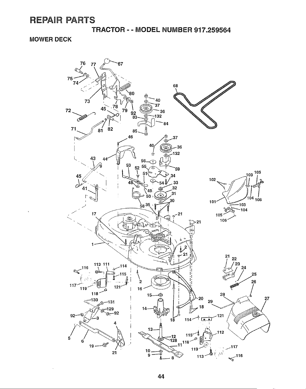
REPAnR PARTS
TRACTOR - - MODEL NUMBER 9!7.259564
MOWER DECK
76
75
74
b
i_ 40
_ 36
_"_132
34
33
32
31
21
\
2
27
44
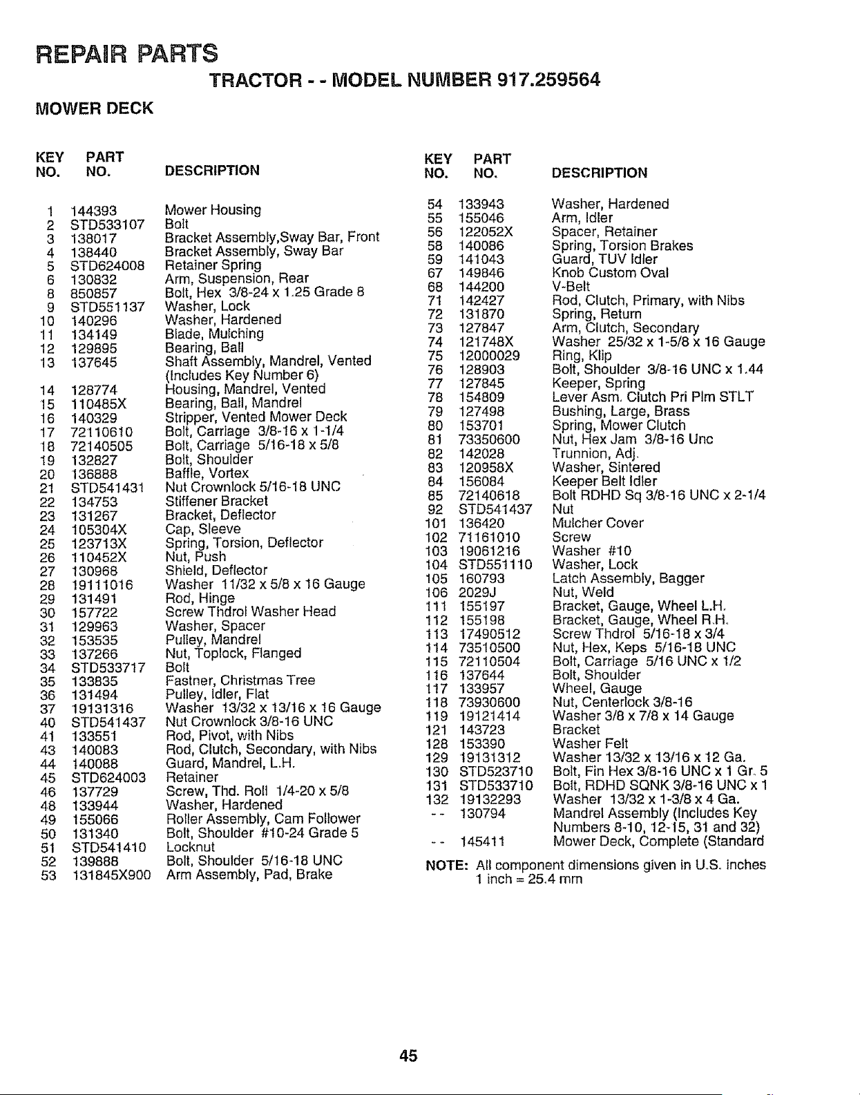
REPAIR PARTS
TRACTOR -- MODEL NUMBER 9'17.259564
MOWER DECK
KEY PART KEY PART
NO. NO. DESCRIPTION NO, NO, DESCRIPTION
1 144393
2 STD533107
3 138017
4 138440
5 STD624008
6 130832
8 850857
9 STD551137
10 140296
11 134149
12 129895
13 137645
14 128774
15 110485X
16 140329
17 72110610
18 72140505
19 132827
20 136888
21 STD541431
22 134753
23 131267
24 105304X
25 123713X
26 110452X
27 130968
28 19111016
29 131491
30 157722
31 129963
32 153535
33 137266
34 STD533717
35 133835
36 131494
37 19131316
40 STD541437
4t 133551
43 140083
44 140088
45 STD624003
46 137729
48 133944
49 155066
50 131340
51 STD541410
52 139888
53 131845X900
Mower Housing 54
Bolt 55
Bracket Assembly,Sway Bar, Front 56
Bracket Assembly, Sway Bar 58
Retainer Spring 59
Arm, Suspension, Rear 67
Bolt, Hex 3/8-24 x 1.25 Grade 8 68
Washer, Lock 71
Washer, Hardened 72
Blade, Mufching 73
Bearing, Ball 74
Shaft Assembly, Mandrel, Vented 75
(Includes Key Number 6) 76
Housing, Mandrel, Vented 77
Bearing, Bail, Mandrel 78
Stripper, Vented Mower Deck 79
Bolt, Carriage 3/8-16 x 1-1/4 80
Bolt, Carriage 5/I6-18 x 5/8 81
Bolt, Shoulder 82
Baffle, Vortex 83
Nut Crownlock 5/16-18 UNC 84
Stiffener Bracket 85
Bracket, Deflector 92
Cap, Sleeve 101
Spring, Torsion, Deflector 102
Nut, Push 103
Shield, Deflector 104
105
Washer 11/32 x 5/8 x 16 Gauge 106
Rod, Hinge
Screw Tt_drolWasher Head 111
Washer, Spacer 112
Pulley, Mandrel 113
Nut, Toplock, Flanged 114
Bolt t!5
Fastner, Christmas Tree 116
Pulley, idler, Flat 1t7
Washer t3/32 x 13/16 x 16 Gauge 118
Nut Crownlock 3/8-16 UNC 119
Rod, Pivot, with Nibs 121
Rod, Clutch, Secondary, with Nibs 128
Guard, Mandrel, L.H. 129
Retainer 130
Screw, Tied. Roll 1/4-20 x 5/8 !31
Washer, Hardened 132
RoIler Assembly, Cam Follower _"
Bolt, Shoulder #10-24 Grade 5
Locknut - -
Bolt, Shoulder 5/16-18 UNC
Arm Assembly, Pad, Brake
133943
155046
122052X
140086
t41043
149846
144200
142427
131870
127847
121748X
12000029
128903
127845
154809
127498
153701
73350600
142028
120958X
156084
72140618
STD541437
136420
71161010
19061216
STD551110
160793
2029J
155197
155198
17490512
73510500
72110504
137644
133957
73930600
19121414
143723
153390
19131312
STD523710
STD533710
19132293
130794
145411
Washer, Hardened
Arm, Idler
Spacer, Retainer
Spring, Torsion Brakes
Guard, TUV Idler
Knob Custom Oval
V-Belt
Rod, Clutch, Primary, with Nibs
Spring, Return
Arm, Clutch, Secondary
Washer 25/32 x 1-5/8 x 16 Gauge
Ring, Klip
Bolt, Shoulder 3/8-16 UNC x 1.44
Keeper, Spring
Lever Asm. Clutch Pri Plm STLT
Bushing, Large, Brass
Spring, Mower Clutch
Nut, Hex Jam 3/8-16 Unc
Trunnion, Adj.
Washer, Sintered
Keeper Belt idler
Bolt RDHD Sq 3/8-16 UNC x 2-1/4
Nut
Mulcher Cover
Screw
Washer #10
Washer, Lock
Latch Assembly, Bagger
Nut, Weld
Bracket, Gauge, Wheel LH.
Bracket, Gauge, Wheel RH.
Screw Thdrol 5/16-18 x 3/4
Nut, Hex, Keps 5/16-18 UNC
Bolt, Carriage 5/16 UNC x 1/2
Bolt, Shoulder
Wheel, Gauge
Nut, Centedock 3/8-16
Washer 3/8 x 7/8 x 14 Gauge
Bracket
Washer Felt
Washer 13/32 x 13/16 x 12 Ga.
Bolt, Fin Hex 3/8-16 UNC x 1 Gr. 5
Bolt, RDHD SQNK 3/8_16 UNC x 1
Washer 13/32 x 1-3/8 x 4 Ga.
Mandrel Assembly (Includes Key
Numbers 8-10, 12q5, 31 and 32)
Mower Deck, Complete (Standard
NOTE: All component dimensions given in US° inches
1 inch = 25.4 mm
45
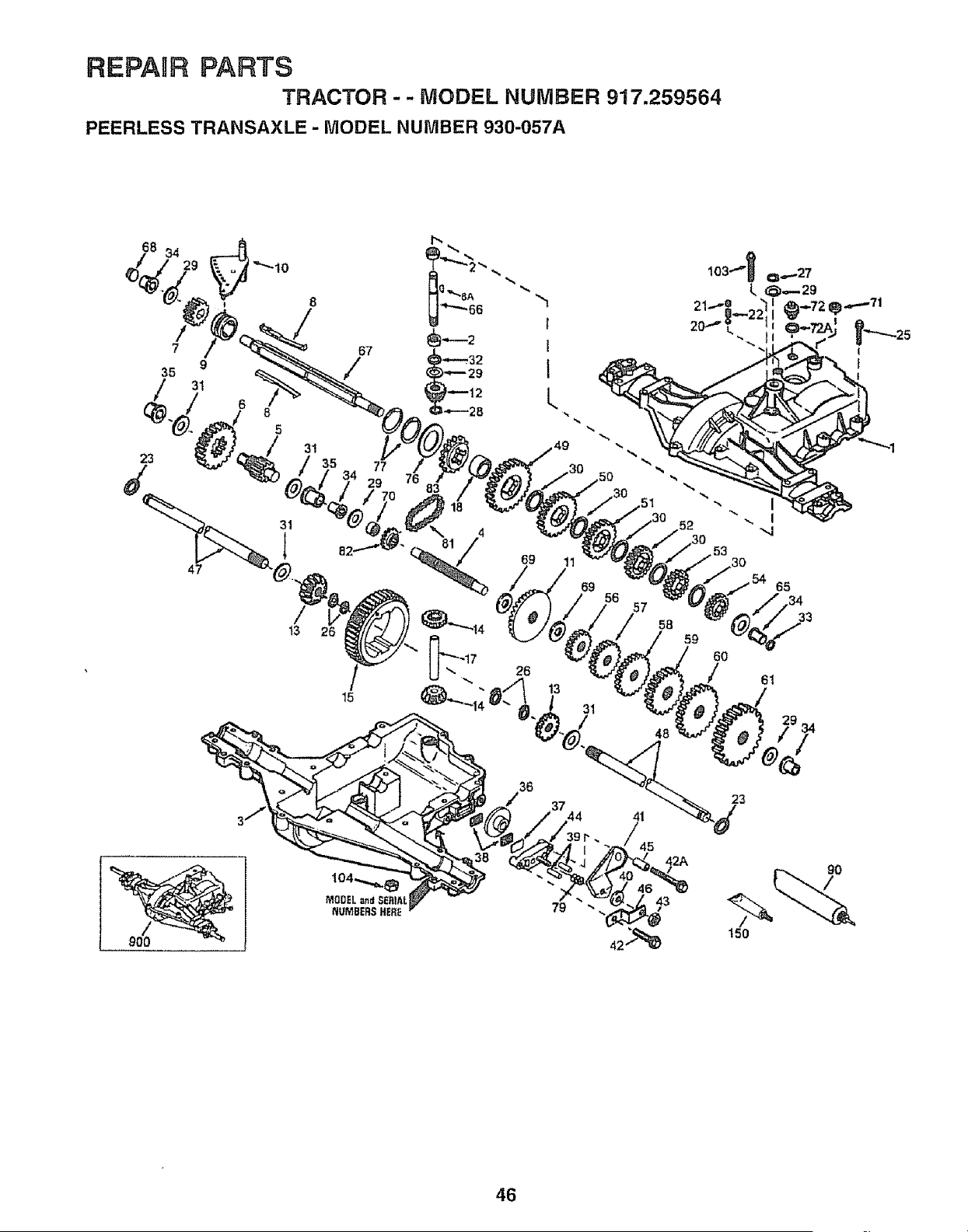
REPAIR PARTS
TRACTOR - - MODEL NUMBER 917.259564
PEERLESS TRANSAXLE - MODEL NUMBER 930-057A
68 34
/
7
35
23
9
31
47
6
8
5
31
/
13
67
/
35 77
29 76
15
42A
90
79
43
42
150
46
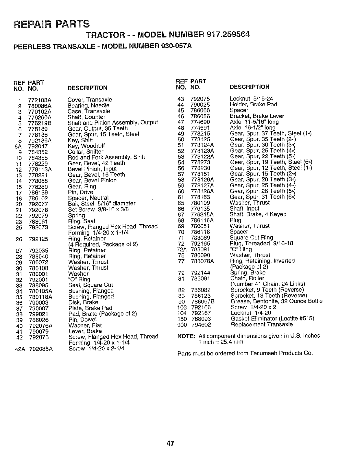
REPAUR PARTS
TRACTOR - - MODEL NUMBER 917.259564
PEERLESS TRANSAXLE - MODEL NUMBER 930-057A
REF PART REF PART
NO. NO. DESCRIPTION NO. NO. DESCRIPTION
1 772108A Cover, Transaxle 43 792075
2 780086A Bearing, Needle 44 790025
3 770102A Case, Transaxle 45 786066
4 776260A Shaft, Counter 46 786086
5 776219B Shaft and Pinion Assembly, Output 47 774690
6 778139 Gear, Output, 35 Teeth 48 774691
7 778136 Gear, Spur, 15 Teeth, Sleel 49 778215
8 792136A Key, Shift 50 778125
8A 792047 Key, Woodruff 51 776124A
9 784352 Collar, Shifter 52 778123A
10 784355 Rod and Fork Assembly, Shift 53 778122A
11 778229 Gear, Bevel, 42 Teeth 54 778273
12 778113A Bevel Pinion, Input 56 778230
13 778221 Gear, Bevel, 16Teeth 57 778151
14 778068 Gear, Bevel Pinion 58 778126A
15 778260 Gear, Ring 59 778127A
'17 786139 Pin, Drive 60 778128A
t8 786102 Spacer, Neutral 61 778163
20 792077 Ball, Steel 5/t6" diameter 65 780109
21 792078 Set Screw 3/8_16 x 3/8 66 776135
22 792079 Spring 67 776315A
23 788061 Ring, Seal 68 786116A
25 792073 Screw, Flanged Hex Head, Thread 69 780051
Forming 1/4-20 x 1-1/4 70 786118
26 792125 Ring, Retainer 71 788069
(4 Required, Package of 2) 72 792165
27 792035 Ring, Retainer 72A 788091
28 788040 Ring, Retainer 76 780090
29 780072 Washer, Thrust 77 788078A
30 780108 Washer, Thrust
31 780001 Washer 79 792144
32 79200'1 "O" Ring 81 786081
33 788095 Seat, Square Cut
34 780105A Bushing, Flanged 82 786082
35 780118A Bushing, Flanged 83 786123
36 790003 Disk, Brake 90 788067B
37 790007 Plate, Brake Pad 103 792166
38 799021 Pad, Brake (Package of 2) 104 792167
39 786026 Pin, Dowel 150 788093
40 792076A Washer, Flat 900 794602
41 790079 Lever, Brake
42 792073 Screw, Flanged Hex Head, Thread
Forming 1/4-20 x 1-1/4
42A 792085A Screw t/4-20 x 2-1/4
Locknut 5/16-24
Holder, Brake Pad
Spacer
Bracket, Brake Lever
Axle 11-5/16" tong
Axle 16-1/2" long
Gear, Spur, 37 Teeth, Steel (1.,)
Gear, Spur, 35 Teeth (2.,)
Gear, Spur, 30 Teeth _(3)J
Gear, Spur, 25 Teeth __(4)
Gear, Spur, 22 Teeth (5)
Gear, Spur, 19 Teeth, Steel (6_)
Gear, Spur, t2 Teeth, Steel (1,,)
Gear, Spur, 15 Teeth (2.,)
Gear, Spur, 20 Teeth (34)
Gear, Spur, 25 Teeth (4_)
Gear, Spur, 28 Teeth (5_)
Gear, Spur, 31 Teeth (6_)
Washer, Thrust
Shaft, Input
Shaft, Brake, 4 Keyed
Plug
Washer, Thrust
Spacer
Square Cut Ring
Plug, Threaded 9/16-18
"O" Ring
Washer, Thrust
Ring, Retaining, Inverted
(Package of 2)
Spring, Brake
Chain, Roller
(Number 41 Chain, 24 Links)
Sprocket, 9 Teeth (Reverse)
Sprocket, 18 Teeth (Reverse)
Grease, Bentonite, 32 Ounce Bottle
Screw 1/4-20 x 2
Locknut 1/4-20
Gasket Eliminator (Loctite #515)
Replacement Transaxle
NOTE: All component dimensions given in UoS. inches
! inch = 25,4 mm
Parts must be ordered from Tecumseh Products Co.
47
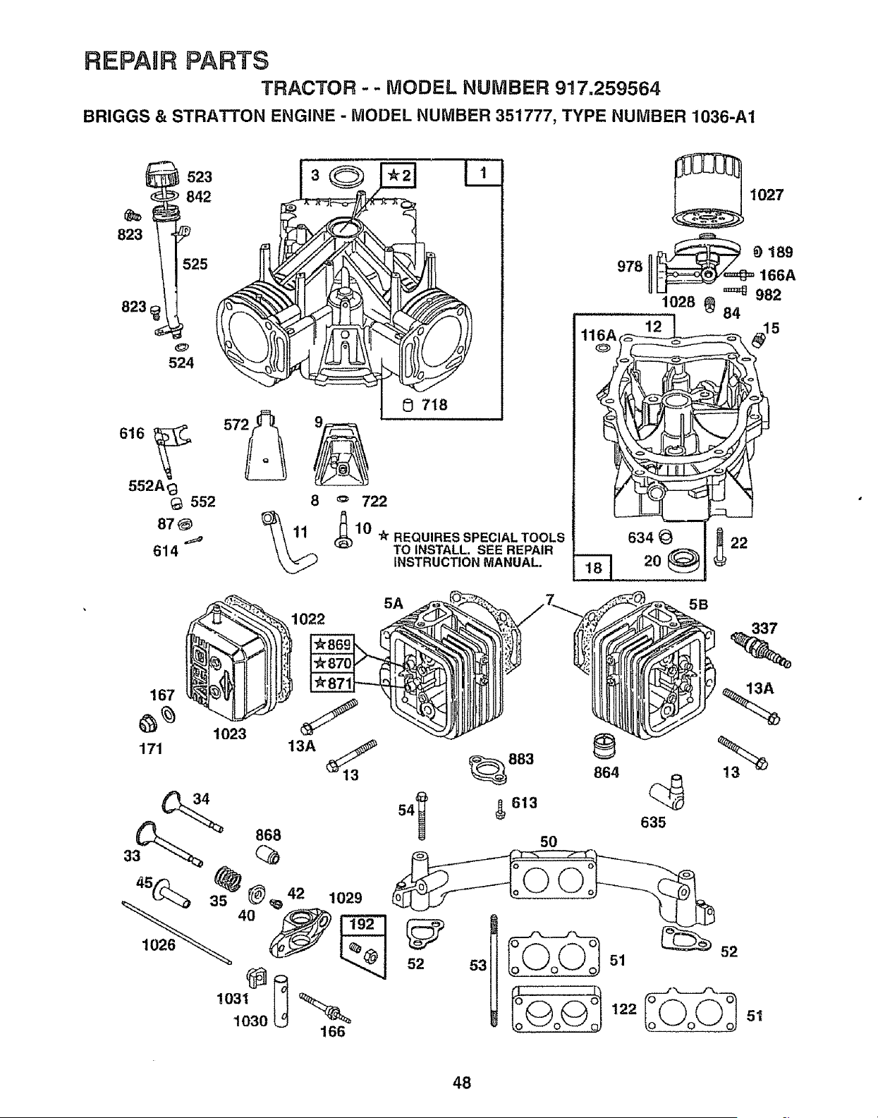
REPABRPARTS
TRACTOR - - MODEL NUMBER 917.259564
BRIGGS & STRATTON ENGINE - MODEL NUMBER 351777, TYPE NUMBER 1036-A1
523
842
823
823
524
552 8 '= 722
87_.,_
614
0 718
_;1 _r REQUIRES SPECIAL TOOLS
0
TO INSTALL. SEE REPAIR
INSTRUCTION MANUAL.
978
20 _22
5A
5B
1022
167
171
1023
13A
! 031 o
1030 166 o
52
122 51
48
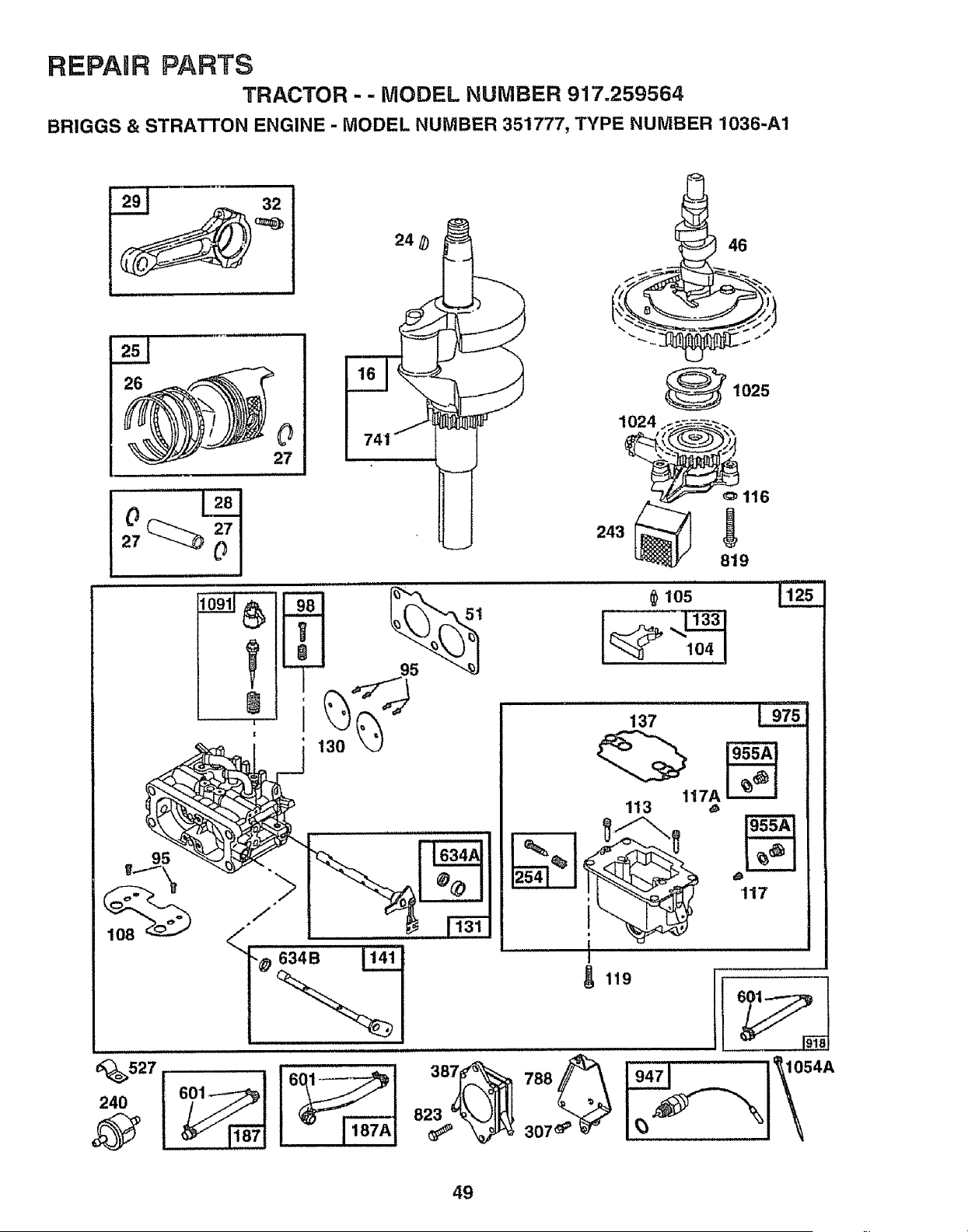
REPAnR PARTS
TRACTOR - - MODEL NUMBER 917.259564
BRIGGS & STRATTON ENGINE - MODEL NUMBER 351777, TYPE NUMBER 1036-A1
240
o116
243
819
105
137
117A
113
117
I '
119
i
387
823
_ _1054A
\
49
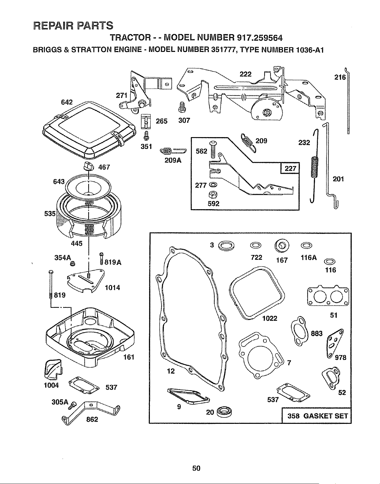
REPANRPARTS
TRACTOR - - MODEL NUMBER 917.259564
BRIGGS & STRATTON ENGINE - MODEL NUMBER 351777, TYPE NUMBER 1036-A1
467
643
535
445
354_819A
1004 _ 537
265 307
g
351
209A
222
209 23;
592
(
201
9
722 167
116A
116
51
7
358 GASKET SET
50
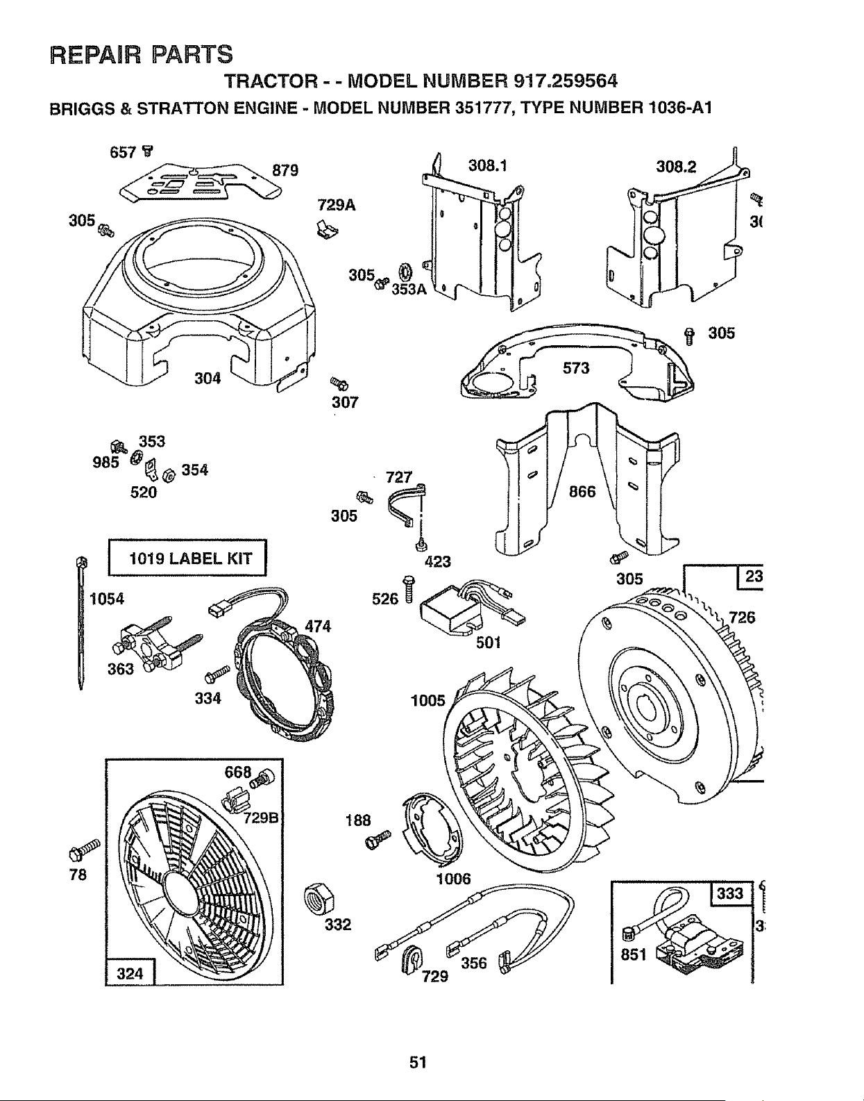
REPAIR PARTS
TRACTOR - - MODEL NUMBER 917.259564
BRIGGS & STRATTON ENGINE - MODEL NUMBER 35'1777, TYPE NUMBER 1036-A1
305
657 _€
78
353
985 @_@ 354
52O
304
I 1019 LABEL KIT
1054
363
334
668
729A
308.1
| o 3(
51
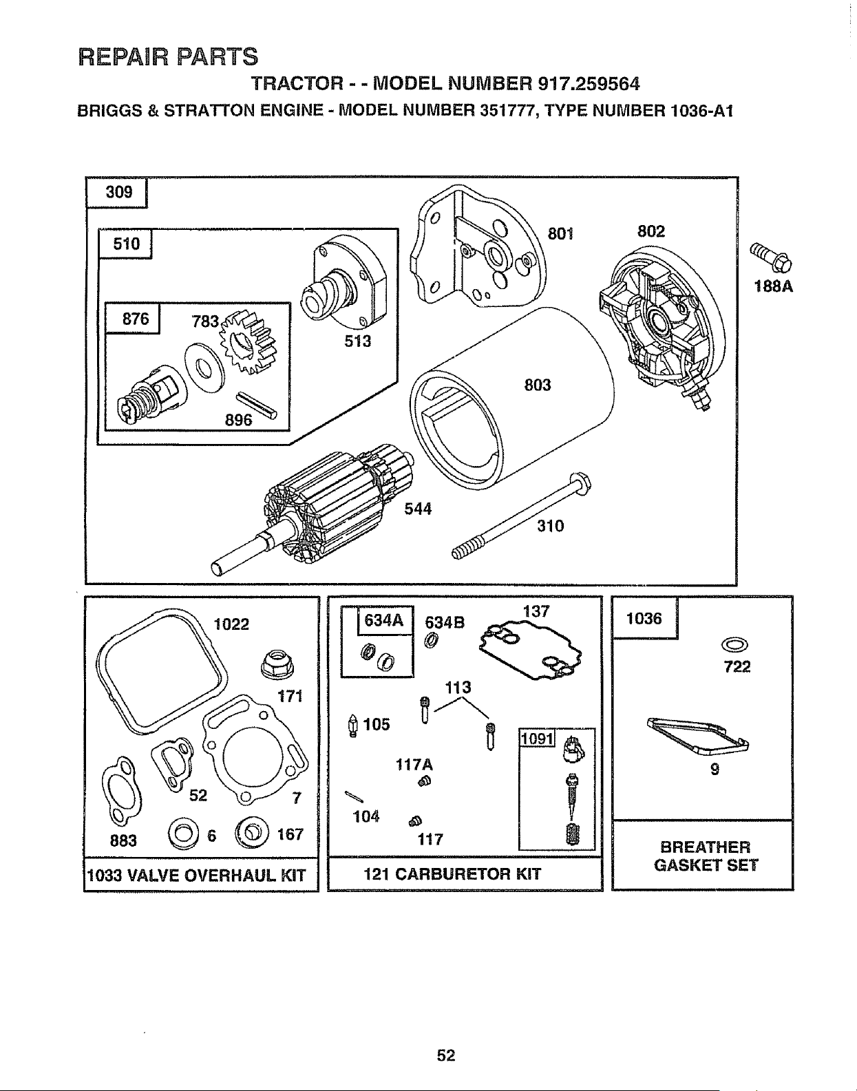
REPANR PARTS
TRACTOR - - MODEL NUMBER 917.259564
BRIGGS & STRATrON ENGINE - MODEL NUMBER 351777, TYPE NUMBER 1036-A1
3o,I ..........
783
513
803
544
310
802
188A
1022
171
1033 VALVE OVERHAUL KIT
113
$105 __
117A
104
117
0
121 CARBURETOR KIT
1036
722
9
BREATHER
GASKET SET
52
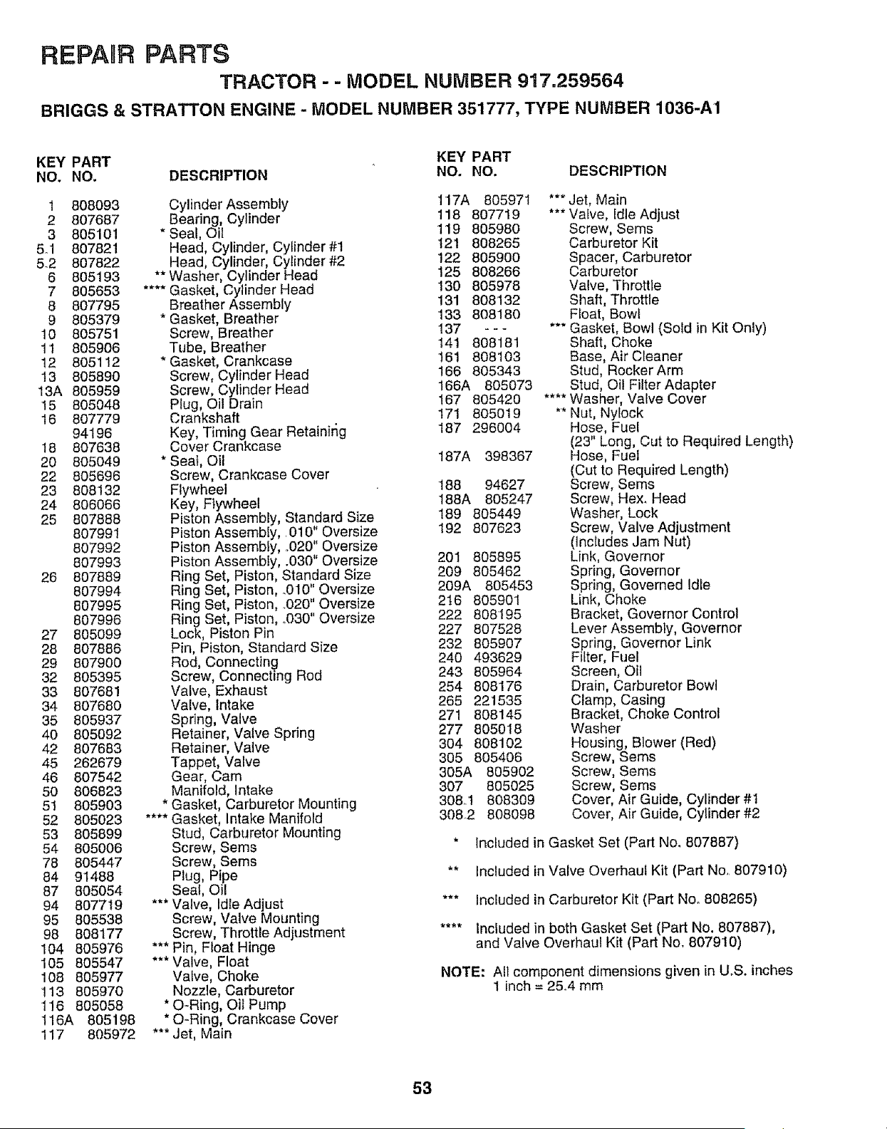
REPARR PARTS
TRACTOR - - MODEL NUMBER 917,259564
BRIGGS & STRATTON ENGINE - MODEL NUMBER 351777, TYPE NUMBER 1036-A1
KEY PART KEY PART
NO. NO. DESCRIPTION NO. NO. DESCRIPTION
1 808093
2 807687
3 805101
5ol 807821
5.2 807822
6 805193
7 805653
8 807795
9 805379
10 805751
1'I 805906
12 805112
t3 805890
13A 805959
15 805048
16 807779
94196
18 807638
20 805049
22 805696
23 808132
24 806066
25 807888
807991
807992
807993
26 807889
807994
807995
807996
27 805099
28 807886
29 807900
32 805395
33 807681
34 807680
35 805937
40 805092
42 807683
45 262679
46 807542
50 806823
5t 805903
52 805023
53 805899
54 805006
78 805447
84 91488
87 805054
94 807719
95 805538
98 808177
104 805976
105 805547
108 805977
!13 805970
116 805058
t16A 805198
117 805972
Cylinder Assembly 117A 805971
118 807719
Bearing, Cylinder 119 805980
* Seal, Oil
Head, Cylinder, Cylinder #1 t21 808265
Head, Cylinder, Cylinder #2 122 805900
**Washer, Cylinder Head 125 808266
.... Gasket, Cylinder Head 130 805978
Breather Assembly 131 808132
* Gasket, Breather 133 808180
Screw, Breather I37 - - -
Tube, Breather 141 808181
* Gasket, Crankcase t61 808103
Screw, Cylinder Head 166 805343
Screw, Cylinder Head 166A 805073
t67 805420
Plug, Oil Drain
Crankshaft 171 805019
Key, Timing Gear Retainir_g 187 296004
Cover Crankcase
* Seat, Oil 187A 398367
Screw, Crankcase Cover
Flywheel 188 94627
Key, Flywheel 188A 805247
Piston Assembly, Standard Size 189 805449
Piston Assembly,. 010" Oversize t92 807623
Piston Assembly, ..020" Oversize
Piston Assembly, .030" Oversize 201 805895
Ring Set, Piston, Standard Size 209 805462
Ring Set, Piston, .010" Oversize 209A 805453
Ring Set, Piston, .020" Oversize 2t6 805901
Ring Set, Piston, _030" Oversize 222 808195
Lock, Piston Pin 227 807528
Pin, Piston, Standard Size 232 805907
Rod, Connecting 240 493629
Screw, Connecting Rod 243 805964
Valve, Exhaust 254 808176
Valve, Intake 265 221535
Spring, Valve 271 808145
Retainer, Valve Spring 277 805018
Retainer, Valve 304 808102
Tappet, Valve 305 805406
Gear, Cam 305A 805902
Manifold, Intake 307 805025
* Gasket, Carburetor Mounting 308.'1 808309
.... Gasket, Intake Manifold 306.2 808098
Stud, Carburetor Mounting
Screw, Sems
Screw, Seres
Plug, Pipe
Seal, Oil
*** Valve, Idle Adjust
Screw, Valve Mounting
Screw, Throttle Adjustment
*** Pin, Float Hinge
*** Valve, Float
Valve, Choke
Nozzle, Carburetor
* O-Ring, Oil Pump
* Q-Ring, Crankcase Cover
*** Jet, Main
*** Jet, Main
*** Valve, Idle Adjust
Screw, Serns
Carburetor Kit
Spacer, Carburetor
Carburetor
Valve, Throttle
Shaft, Throttle
Float, Bowl
*** Gasket, Bowl (Sold in Kit Only)
Shaft, Choke
Base, Air Cleaner
Stud, Rocker Arm
Stud, Oil Filter Adapter
.... Washer, Valve Cover
** Nut, Nylock
Hose, Fuel
(23" Long, Cut to Required Length)
Hose, Fuel
(Cut to Required Length)
Screw, Sems
Screw, Hex. Head
Washer, Lock
Screw, Valve Adjustment
(includes Jam Nut)
Link, Governor
Spring, Governor
Spring, Governed Idle
Link, Choke
Bracket, Governor Control
Lever Assembly, Governor
Spring, Governor Link
Filter, Fuel
Screen, Oil
Drain, Carburetor Bowl
Clamp, Casing
Bracket, Choke Control
Washer
Housing, Blower (Red)
Screw, Seres
Screw, Seres
Screw, Seres
Cover, Air Guide, Cylinder #I
Cover, Air Guide, Cylinder #2
* Included in Gasket Set (Part No. 807887)
** Included in Valve Overhaul Kit (Part No,. 807910)
*** Included in Carburetor Kit (Part No. 808265)
.... Included in both Gasket Set (Part No. 807887),
and Valve Overhaul Kit (Part No, 807910)
NOTE: All component dimensions given in UoS. inches
1 inch = 25°4 mm
53

REPAIR PARTS
TRACTOR - - MODEL NUi',,/IBIER917.259564
BRIGGS & STRATTON ENGINE - MODEL NUMBER 351777, TYPE NUMBER 1036-A1
KEY PART KEY PART
NO, NO, DESCRIPTION NO. NO. DESCRIPTION
309 494990 Motor, Starter 802 494988 Cap, End
310 94004 Bolt, Thru 803 494205 Housing, Starter
324 494439 Screen, Rotating 819 805894 Screw, Seres
332 806028 Nut, Hex 819A 805057 Screw, Hex Head
333 492341 Armature, Magneto 823 805317 Screw, Mounting
334 805407 Screw, Mounting 842 270920 O-Ring
337 491055 Plug, Spark 85t 493880 Terminal, Ignition Cable
351 805169 Screw, Hex Head 862 805896 Bracket, Air Cleaner
353 92791 Washer, Lock 864 805083 Liner, Exhaust Port
353A 806101 Washer, Lock 866 805738 Valley Cover, Air Guide
354 90576 Nut, Hex 868 805094 Seal, Valve Guide
354A 810078 Nut, Hex 869 805085 Seat, intake Valve
356 493792 Wire, Ground 870 805086 Seat, Exhaust Valve
358 807887 Gasket Set 871 805084 Guide, Valve
363 19203 Puller, Flywheel 876 495877 Kit, Retainer
387 808287 Pump, Fuel 879 805841 Cover, Carburetor
423 805260 Screw, Sems 883 805024 **** Gasket, Exhaust Manifold
445 394018 Cartridge, Air Cleaner 896 94288 Pin, Roll
467 491875 Knob, Air Cleaner 9t8 393815 Hose, Vacuum
474 393295 Stator, Alternator' 947 808175 Solenoid
501 394890 Regulator, Alternator 955A 807723 Plug, Main Jet
510 495878 Drive, Starter 975 808179 Bowl, Float
513 398003 Clutch Assembly 978 805250 * Gasket, Oil Filter Adapter
520 93722 Terminal, Spade 982 805030 Screw, Sems
523 807985 Dipstick 985 398525 Insulator Assembly
524 805011 Seal, FillerTube 1004 805892 Tube, Air Inlet
525 807611 Tube, Oil Filler 1005 808082 Fan, Flywheel
526 805448 Screw, Seres t006 224413 Retainer, Fan
527 223167 Clamp, Fuel Pipe t014 808105 Shierd, Carburetor Air Cleaner
535 272490 Element, Foam 1022 806039 **** Gasket, Valve Cover
537 806013 * Gasket, Air Cleaner 1023 805100 Cover, Valve
544 490309 Armature, Starter 807665 Cover, Valve (Used on Cylinder #1
552 805412 Bushing, Governor Shaft on Fuel Pump Applications)
552A 805413 Bushing, Governor Shaft 1024 807546 Pump Assembly, Oil
562 805381 Bolt 1025 805313 Slider, Governor
572 805197 Baffle, Breather 1026 805352 Rod, Push Intake, Steel
573 807663 Plate, Back 805617 Rod, Push, Aluminum
592 805383 Nut, Hex (Used on Exhaust Side Only)
601 93053 Clamp, Hose 1027 492932 Filter, Oil
613 805158 Screw, Seres 1028 805292 Adapter, Oil Filter
614 805417 Pin, Cotter 1029 808096 Arm, Rocker
616 807596 Crank, Governor 1030 805342 Shaft, Rocker Arm
634 805416 Washer, Governor Shaft t031 805341 Support, Rocker Arm
634A 808183 *** Seal, Shaft 1033 807910 Overhaul Kit, Valve
634B 805544 *** Seal, Shaft t036 807688 Breather Gasket Set
635 805529 Elbow, Spark Plug 1054 270723 Tie, Wire
642 807862 Cover, Air Cleaner 1054A 280275 Tie, Wire
643 805631 Plate, Cartridge 1091 805862 ***Cap, Limiter
657 805009 Screw, Sems
668 805402 Spacer RPM Settings: Low: 1200-1600, High: 3200-3400
718 805103 Dowel, Crankcase
722 805483 * Seal, Breather Screw * Included in Gasket Set (Part No. 807887)
726 807805 Gear, Flywheel Ring
727 805505 Shield, Starter ** Included in Valve Overhaul Kit (Part Nov 807910)
729 805641 Grommet
729A 224356 Clip, Debris *** Included in Carburetor Kit (Part No. 808265)
729B 280470 Clip, Wire
741 805675 Gear, Timing .... Included in both Gasket Set (Part No. 807887),
783 280104 Gear and Valve Overhaul Kit (Part No.. 807910)
788 807685 Bracket, Fuel Pump
801 394856 Cap, Drive NOTE: All component dimensions given in U.S. inches
1 inch = 25°4 mm
54
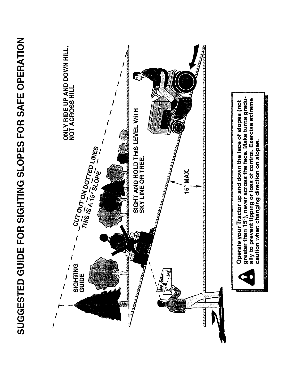
Z
0
B
I.-
t.r
iil
0
ILl
n-
O
I.I.
ILl
0
...I
t,/)
m
I-,
t_
(/)
n-
O
I.!.1
Q
m
Q
ILl
I--
(/)
ILl
t,/}
../
,.,I
m
Z
o
"'8
_a,-,-
tro
zO
Oz
/
/
/
/
/
/
/
/
/ t
/
/
/
/
:4
OWNER'S
MANUAL
MODEL NO.
917.259564
IF YOU NEED
REPAIR SERVICE
OR PARTS:
FOR REPAIR SERVICE, CALL
THIS TOLL FREE NUMBER:
1-800-4-REPAIR
(1-800-473-7247)
FOR REPLACEMENT PARTS
INFORMATION AND
ORDERING, CALL THIS
TOLL FREE NUMBER:
1-800-FON-PART
(1-aoo..366-727a)
FOR CONSUMER ASSISTANCE
HOT LINE, CALL THIS
TOLL FREE NUMBER:
1-800-659-5917
160978 5,20.97 TR
®
19.5 HP
ELECTRIC START
42" MOWER
6 SPEED TRANSAXLE
LAWN TRACTOR
Each tractor has its own model number. Each engine has
its own model number:
The model number for your tractor wilt be found on the
model plate located under the seat.
The model number for' your' engine will be found on the
blower housing of the engine.
Al! parts listed herein may be ordered from any Sears,
Roebuck and Co. Service Center/Department and most Re-
tail Stores,
WHEN ORDERING REPAIR PARTS, ALWAYS GIVE THE
FOLLOWING INFORMATION:
• PRODUCT- TRACTOR
• MODEL NUMBER - 917.259564
• ENGINE MODEL NO. - 351777-1036=A1
• PART NUMBER
• PART DESCRIPTION
Your Sears merchandise has added value when you
consider Sears has service units nationwide staffed with
Sears trained technicians_, professional technicians
specifically trained to insure that we meet our pledge to
you, we service what we sell,
Printed in U,S.A.
IIIIIIIIIIIIIIIIIIIIIIIIIHIIIIIIIIIII II IIIIIIIIIIIIIIIIII


